Cisco 1240 Hardware Installation Manual
Connected grid router
Hide thumbs
Also See for 1240:
- Configuration manual (40 pages) ,
- Design and deployment manual (184 pages) ,
- Hardware installation manual (90 pages)
Table of Contents
Advertisement
Quick Links
Download this manual
See also:
Configuration Manual
Cisco 1240 Connected Grid Router
Hardware Installation Guide
First Published: March 2013
Last Updated: January, 2014
Part Number: OL-26223-04
Cisco Systems, Inc.
www.cisco.com
Cisco has more than 200 offices worldwide.
Addresses, phone numbers, and fax numbers
are listed on the Cisco website at
www.cisco.com/go/offices.
Text Part Number: OL-26223-04
Advertisement
Table of Contents

Related Manuals for Cisco 1240


Summary of Contents for Cisco 1240
- Page 1 First Published: March 2013 Last Updated: January, 2014 Part Number: OL-26223-04 Cisco Systems, Inc. www.cisco.com Cisco has more than 200 offices worldwide. Addresses, phone numbers, and fax numbers are listed on the Cisco website at www.cisco.com/go/offices. Text Part Number: OL-26223-04...
- Page 2 OR ITS SUPPLIERS HAVE BEEN ADVISED OF THE POSSIBILITY OF SUCH DAMAGES. Cisco and the Cisco logo are trademarks or registered trademarks of Cisco and/or its affiliates in the U.S. and other countries. To view a list of Cisco trademarks, go to this URL: www.cisco.com/go/trademarks.
-
Page 3: Table Of Contents
Exterior Hardware Overview Interior Hardware Overview 3-10 Hardware Features Detailed Description 3-12 Router Hardware Exterior Features 3-12 Chassis Enclosure 3-12 Chassis Cable Ports 3-13 Console Port 3-14 SD Flash Memory Module 3-16 Cisco 1240 Connected Grid Router Hardware Installation Guide OL-26223-04... - Page 4 Support for Exterior Door Lock Mounting Bracket Security Panel Mounting the Router C H A P T E R Mounting Kits Overview General Safety Information for Mounting Contents of the Mounting Kits Pole Mount Kit Cisco 1240 Connected Grid Router Hardware Installation Guide OL-26223-04...
- Page 5 Related Information Basic Hardware Installation Connect to the Ethernet Backhaul Network Connecting to AC Power AC Power Cable Connect to AC Power Power and Reset Buttons Accessing the Buttons Related Information Cisco 1240 Connected Grid Router Hardware Installation Guide OL-26223-04...
- Page 6 About 6-22 Connecting 6-22 Related Information 6-22 Connecting the Alarm Port 6-22 About 6-22 Connecting 6-22 Related Information 6-23 Connecting the IRIG-B Port 6-23 About 6-23 Connecting 6-23 Related Information 6-23 Cisco 1240 Connected Grid Router Hardware Installation Guide OL-26223-04...
- Page 7 C H A P T E R Installing or Replacing Antennas 10-1 Lightning Arrestor 10-1 Cisco Connected Grid Modules 10-2 Antennas Overview 10-2 GPS Antenna 10-2 WiFi Antenna 10-3 Connected Grid Module Antennas 10-4 Cisco 1240 Connected Grid Router Hardware Installation Guide OL-26223-04...
- Page 8 BBU Firmware Upgrade 12-4 BBU Capacity 12-4 Preparing to Install the BBU 12-4 Tools You Supply 12-4 Safety Information for Installation 12-4 Safety Warnings 12-4 Preventing Electrostatic Discharge Damage 12-5 Cisco 1240 Connected Grid Router Hardware Installation Guide viii OL-26223-04...
- Page 9 12-28 show environment power 12-33 BBU Technical Specifications 12-33 Router Power Path Selection 12-34 Discharge Conditions 12-34 Charge Conditions 12-35 Operating and Storage Temperatures 12-35 Battery Life 12-35 Cisco 1240 Connected Grid Router Hardware Installation Guide OL-26223-04...
- Page 10 Battery Backup Unit LED 14-6 SD Flash Memory Module LED – SD Card Status 14-7 Related Commands 14-8 Displaying Router SYS LED Status Command 14-8 Cisco CG-OS show led Command 14-8 Cisco 1240 Connected Grid Router Hardware Installation Guide OL-26223-04...
- Page 11 Console Port Copper Interface—Combination Port (SFP and GE Ethernet) SFP Interface—Combination Port (SFP and GE Ethernet) Serial Port AC Power Supply Connector Non-Cisco Module Power Connector Cable and Adapter Specifications SFP Cable Cisco 1240 Connected Grid Router Hardware Installation Guide OL-26223-04...
- Page 12 Contents Cisco 1240 Connected Grid Router Hardware Installation Guide OL-26223-04...
-
Page 13: Unpacking The Router
C H A P T E R Unpacking the Router This chapter includes instructions about how to unpack the Cisco 1240 Connected Grid Router and describes the items that ship with the router. This chapter includes the following sections: Unpacking the Router, page 1-1 •... -
Page 14: Chapter 1 Unpacking The Router
5-5, in the “Mounting the Router” chapter. Strap tool kit BAND-IT strap tool. For details, see the “Strap Tool Kit” section on page 5-6, in the “Mounting the Router” chapter. Antenna plug CGR-ANT-PLUG Cisco 1240 Connected Grid Router Hardware Installation Guide OL-26223-04... -
Page 15: Safety Recommendations
Locate the emergency power-off switch for your installation location. If an electrical accident occurs, you can quickly turn off the power. • Disconnect all power before doing the following: – Installing or removing a chassis Cisco 1240 Connected Grid Router Hardware Installation Guide OL-26223-04... -
Page 16: C H A P T E R 2 Installation Safety And Site Preparation
This section contains important safety warnings for the installation and use of the router. Translated versions of all safety warnings are available in the safety warnings document that shipped with your router, and which is available on Cisco.com. Warning IMPORTANT SAFETY INSTRUCTIONS This warning symbol means danger. -
Page 17: Site Requirements
Ensure that the site is properly prepared before beginning installation. If you are experiencing shutdowns or unusually high errors with your existing equipment, this section can also help you isolate the cause of failures and prevent future problems. Cisco 1240 Connected Grid Router Hardware Installation Guide OL-26223-04... -
Page 18: Pole-Top Installation Requirements
FCC-certified equipment. When used with approved Cisco antennas, Cisco products meet the uncontrolled environmental limits found in OET-65 and ANSI C95.1, 1991. Proper operation of this radio device according to the instructions in this publication results in user exposure substantially below the FCC recommended limits. -
Page 19: Power Guidelines And Requirements
The router exterior Ethernet connector is compliant with Open DeviceNet Vendor Association (ODVA) standards. Cables used with this port must also comply with the ODVA standards. ODVA-compliant cables and connectors meet IP 67 ratings. Cisco 1240 Connected Grid Router Hardware Installation Guide OL-26223-04... -
Page 20: Required Tools And Equipment For Installation And Maintenance
Installing Battery Backup Units • Installing External Non-Cisco Modules • See the Cisco Connected Grid modules installation and configuration guides for the tools and equipment you must supply to install modules, at: www.cisco.com/go/cg-modules Cisco 1240 Connected Grid Router Hardware Installation Guide... -
Page 21: Router Overview
Router Hardware Description This chapter describes the major hardware features of the Cisco 1240 Connected Grid Router (CGR 1240 or router), including the chassis and the internal and external connectors and ports. This chapter contains the following sections: Router Overview, page 3-1 •... -
Page 22: Hardware Compliance
SCADA systems using protocol translation over the IP network. Hardware Compliance For a complete list of regulatory and compliance standards supported by the Cisco CGR 1240 Router, see the Regulatory Compliance and Safety Information for the Cisco 1000 Series Routers at: http://www.cisco.com/en/US/docs/routers/connectedgrid/cgr1000/rcsi/cgr1000.rsci.html... -
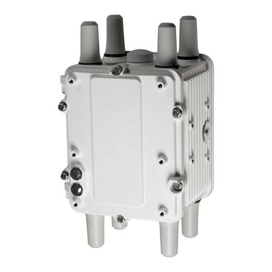
Page 23: Chapter 3 Router Hardware Description
The CGR 1240 hardware assembly is shown in Figure 3-1. Figure 3-1 Cisco 1240 Connected Grid Router with Integrated Antennas Installed This section contains: Exterior Hardware Overview, page 3-4 • Cisco 1240 Connected Grid Router Hardware Installation Guide OL-26223-04... -
Page 24: Exterior Hardware Overview
Router Front Exterior Features Description Detailed Information M8 captive bolts (8) Loosen these bolts to access the router interior. For information about opening the chassis, see the “Opening the Router Chassis” chapter. Cisco 1240 Connected Grid Router Hardware Installation Guide OL-26223-04... - Page 25 Router Bracket and Lock Features Description Detailed Information Mounting bracket Use the mounting bracket with the Cisco pole mount kit to install the router on a pole. For information about router mounting options and procedures, see the “Mounting the Router” chapter.
- Page 26 “Installing the Router” chapter. Mounting bracket posts (4) Attach supported brackets to the router using these mounting posts. For information about router mounting options and procedures, see the “Mounting the Router” chapter. Cisco 1240 Connected Grid Router Hardware Installation Guide OL-26223-04...
- Page 27 SD card port. To access the port after the bracket is installed, you must remove 3 of the bolts that attach the bracket to the router, and rotate the bracket away from the port. For detailed instructions, see the “Mounting the Router” chapter. Cisco 1240 Connected Grid Router Hardware Installation Guide OL-26223-04...
- Page 28 The GPS antenna connects the router GPS, which is described in the “GPS Module” section on page 3-32, to the GPS source. For more information about GPS antenna, including specifications and frequencies supported, see the “GPS Antenna” section on page 10-2. Cisco 1240 Connected Grid Router Hardware Installation Guide OL-26223-04...
- Page 29 “Router LED Locations and States” chapter. Protective vent The chassis vent relieves pressure buildup inside the router chassis. For a description of the vent, see the “Protective Vent” section on page 3-17. Cisco 1240 Connected Grid Router Hardware Installation Guide OL-26223-04...
-
Page 30: Interior Hardware Overview
3-12, later in this chapter, or in other chapters in this document. Figure 3-8 Interior Front Panel Hardware Features Table 3-8, items indicated with Footnote 1 are currently not supported, and will be supported in a Note future software release. Cisco 1240 Connected Grid Router Hardware Installation Guide 3-10 OL-26223-04... - Page 31 “Alarm Port” section on page 3-18. SLOT 3, SLOT4, Install Cisco Connected Grid modules in these four module slots. For more SLOT 5, SLOT 6 information, see the “Module Slots” section on page 3-19 and the “Module...
-
Page 32: Hardware Features Detailed Description
AC Power Supply, page 3-17 • Chassis Enclosure The Cisco CGR 1240 Router industrial enclosure (see Figure 3-1) meets Type 4X and IP67 standards and is designed for deployment in extreme weather. The enclosure can be painted to comply with aesthetic requirements. -
Page 33: Chassis Cable Ports
Unused router ports are sealed with a liquid-tight cover (PG13) to protect the router interior from environmental elements. The router should not be installed unless all unused chassis cable ports are sealed. Leaving chassis ports Caution unsealed can damage the router. Cisco 1240 Connected Grid Router Hardware Installation Guide 3-13 OL-26223-04... -
Page 34: Console Port
DB-9 connector on the other end (for connecting to a PC or terminal). Detailed information about connecting and using the console port is in the “Installing the Router” chapter. Cisco 1240 Connected Grid Router Hardware Installation Guide 3-14 OL-26223-04... - Page 35 Router Hardware Description Hardware Features Detailed Description Figure 3-11 Console Port Detail Specifications Specification Description Connector type RJ-45 Transceiver RS-232 Cable type EIA RJ-45 Pinout See the “Connector and Cable Specifications” appendix. Cisco 1240 Connected Grid Router Hardware Installation Guide 3-15 OL-26223-04...
-
Page 36: Sd Flash Memory Module
Figure 3-12 SD Flash Memory Slot Detail You must use only the Cisco SD card designed to support the router. Using an unsupported SD card can Caution impact the router performance, especially in extreme environmental conditions. 10/100BASE-T Fast Ethernet Connector... -
Page 37: Protective Vent
Serial Ports, page 3-27 • IRIG-B Timing Port, page 3-29 • USB Ports, page 3-30 • Memory, page 3-32 • GPS Module, page 3-32 • WiFi Short-Range Access Point, page 3-34 • Cisco 1240 Connected Grid Router Hardware Installation Guide 3-17 OL-26223-04... -
Page 38: Alarm Port
Open—The open setting indicates that the normal router operating condition has an electrical • current passing through the alarm circuits (DRY contact closed). If this electrical current is no longer detected (DRY contact open), an alarm is generated. Cisco 1240 Connected Grid Router Hardware Installation Guide 3-18 OL-26223-04... -
Page 39: Module Slots
30 volts @ 1 A Module Slots The router has four module slots to support installation of up to four compatible Cisco Connected Grid modules, for additional router WAN and NAN interfaces. Modules should be installed in the slots according to the module slot numbers shown in... -
Page 40: Reset Buttons
The router will temporarily stop operating on the network during the power cycle, then resume operating when power cycle process is complete. Cisco 1240 Connected Grid Router Hardware Installation Guide 3-20 OL-26223-04... -
Page 41: Fast Ethernet And Gigabit Ethernet Ports
Figure 3-15 Router Reset Buttons Fast Ethernet and Gigabit Ethernet Ports The CGR 1240 router has two types of Ethernet port: fast Ethernet and gigabit Ethernet port. These are described in the following sections: Fast Ethernet Ports, page 3-22 •... - Page 42 Fast Ethernet ports are labelled on the router and referred to in software. The ports are shown in Figure 3-15. Figure 3-16 Cisco CG-OS CGR 1240 Router Fast Ethernet and Gigabi Ethernet Ports Table 3-10 CGR 1240 Fast Ethernet Port Naming CGR 1240 Router Label...
- Page 43 Category 5 or better shielded 328 feet (100 meters) transmission twisted-pair (STP) cable 10BASE-T 10 Mbps full-duplex Category 5 or better shielded 328 feet (100 meters) transmission twisted-pair (STP) cable Cisco 1240 Connected Grid Router Hardware Installation Guide 3-23 OL-26223-04...
-
Page 44: Small Form-Factor Pluggable (Sfp) Ports
Hardware Features Detailed Description Small Form-Factor Pluggable (SFP) Ports The router features two fiber optical SFP ports that support optional Cisco rugged SFP modules for Gigabit Ethernet WAN connectivity to a primary substation or control center. The ports are labeled as... -
Page 45: Combo Ports
The SFP modules can be installed or removed while the router is on and operating normally. Supported SFPs Table 3-14 lists the supported SFP modules. See the Cisco 1000 Series Connected Grid Routers Release Notes for the most recent information about Note supported hardware and software. Table 3-14... - Page 46 Gigabit Ethernet Connection Type Gigabit Ethernet ports Copper SFP module ports Fiber optic Table 3-15 Cisco CGR 1240 Gigabit Ethernet and SFP Port Naming CGR 1240 Router Label Cisco CG-OS Software Port Name Cisco IOS Software Port Name ETH 2/1 GE 2/1...
-
Page 47: Serial Ports
• connecting to the synchronous serial interface • Signaling standard required by the device Serial ports can be configured as DTE or DCE, depending on the serial cable used • Cisco 1240 Connected Grid Router Hardware Installation Guide 3-27 OL-26223-04... - Page 48 Hardware Features Detailed Description Serial Port Cables You can order a Cisco RJ-45 shielded serial-transition cable that has the appropriate connector for the standard you specify. The documentation for the device should indicate the standard used for that device. The router end of the shielded serial transition cable has a DB-25 connector, which connects to the DB-25 port on a serial grid router WAN interface card.
-
Page 49: Irig-B Timing Port
Figure 3-20 Router IRIG-B Timing Port Note The IRIG-B timing port supports timing output only. Table 3-17 Supported IRIG Serial Time Code Formats Format Modulations Carrier Frequency Code Expression Interface Cisco 1240 Connected Grid Router Hardware Installation Guide 3-29 OL-26223-04... -
Page 50: Usb Ports
The USB ports operate at the following speeds: 1 Mbps • • 12 Mbps • 480 Mbps Currently not supported. This hardware feature will be supported in a future software release. Note Cisco 1240 Connected Grid Router Hardware Installation Guide 3-30 OL-26223-04... - Page 51 To prevent USB devices from being stolen or accidently removed, secure any connected USB device with a locking mechanism. Specifications Specification Description USB Port Type Type A USB Device Types Supported USB 1.1, USB 2.0 Power Output 2.5W (+5V +/-5% @ 500mA) per port Cisco 1240 Connected Grid Router Hardware Installation Guide 3-31 OL-26223-04...
-
Page 52: Memory
This section has information on: GPS LED, page 3-33 • • GPS Specifications, page 3-33 • Using the CLI to Display GPS Current Time and Location for a Cisco CG-OS Router, page 3-33 Cisco 1240 Connected Grid Router Hardware Installation Guide 3-32 OL-26223-04... - Page 53 38 seconds Error correction Space Based Augmentation Systems (SBAS) Using the CLI to Display GPS Current Time and Location for a Cisco CG-OS Router Displaying GPS Current Time and Location for a Cisco CG-OS Router, page 3-33 • Displaying GPS Current Time and Location for a Cisco IOS Router, page 3-33 •...
-
Page 54: Wifi Short-Range Access Point
WiFi connection to connect to or administer the router. WiFi Hardware The CGR 1240 router is equipped with an 802.11b/g/n 2.4GHz radio that works as the access point to provide WiFi connectivity to the router. The WiFi hardware is a Broadcom BCM4325 chipset based radio with an external WiFi antenna. -
Page 55: Real-Time Clock (Rtc)
Displaying WiFi Configuration Information for a Cisco IOS Router Note For a CGR 1240 router using the Cisco IOS operating system, the WiFi interface is identified as ‘Dot11Radio 2/1’. To display WiFi configuration information, enter any or all of the following commands in priveleged EXEC or user EXEC mode:: show interface dot11Radio 2/1—Displays the status of the interface as up or down, the five second... - Page 56 Chapter 3 Router Hardware Description Hardware Features Detailed Description Cisco 1240 Connected Grid Router Hardware Installation Guide 3-36 OL-26223-04...
-
Page 57: Chapter 4 Opening The Router Chassis
C H A P T E R Opening the Router Chassis This chapter describes how to open the Cisco 1240 Connected Grid Router (CGR 1240 or router) door so that you can access the interior of the chassis, and contains these sections: Opening the Router Door, page 4-1 •... -
Page 58: Safety Information
Router Door, Showing Captive Bolts Captive bolt (6) Order of Loosening and Tightening Door Bolts Cisco recommends that you loosen and tighten the door bolts in the order shown in Figure 4-2. The chassis door features an environmental seal that protects the chassis against environmental elements when the door is closed. -
Page 59: Opening The Door
Figure 4-3 is a detailed view of a captive bolt. Note After all six bolts are loose, swing the door open on the left-side hinges, as shown in Figure 4-4. Step 2 Cisco 1240 Connected Grid Router Hardware Installation Guide OL-26223-04... -
Page 60: Closing The Door
Figure 4-2, this time using 6 to 7 foot-pounds of torque. Step 4 Replace any locking mechanism, such as a padlock, on the door lock post. Figure 4-3 Captive Bolt Detail Cisco 1240 Connected Grid Router Hardware Installation Guide OL-26223-04... -
Page 61: Door Features
These are examples of the door state event messages: Sep 24 08:04 Router %$ VDC-1 %$ %FCPLMGR-2-FCPLMGR_DOOR_ALARM: door/lid has been closed Sep 24 08:04 Router %$ VDC-1 %$ %FCPLMGR-2-FCPLMGR_DOOR_ALARM: door/lid has been open Cisco 1240 Connected Grid Router Hardware Installation Guide OL-26223-04... -
Page 62: Support For Exterior Door Lock
The lock post supports a lock with a shank diameter of up to 5/16 inches (such as Master Lock part number 176). Figure 4-7 shows an external lock applied to the lock post on the router door. Cisco 1240 Connected Grid Router Hardware Installation Guide OL-26223-04... - Page 63 Chapter 4 Opening the Router Chassis Door Features Figure 4-6 Door Lock Post Detail Cisco 1240 Connected Grid Router Hardware Installation Guide OL-26223-04...
-
Page 64: Mounting Bracket Security Panel
SD card slot. The security panel is shipped with the Mounting Bracket Kit. For security panel details and installation instructions, see the “Mounting the Router” chapter. Cisco 1240 Connected Grid Router Hardware Installation Guide OL-26223-04... -
Page 65: Mounting Kits Overview
Mounting the Router This chapter describes the safety information, equipment, and procedures required to mount the Cisco 1240 Connected Grid Router (CGR 1240 or router) on a vertical pole or streetlight. This chapter contains these sections Mounting Kits Overview, page 5-1 •... -
Page 66: Chapter 5 Mounting The Router
Pole Mount Kit When to Use Use the Cisco pole mount kit to install the mounting plate on any pole or streetlight. The kit supports poles that meet the following criteria: Size—2 to 16 inch diameter poles •... - Page 67 “Install the Split lock washer (3/8 inch) Mounting Plate onto a Pole” section on page 5-8. Nut (3/8-16) Carriage bolt (3/8-16 x 7 inches) Cisco 1240 Connected Grid Router Hardware Installation Guide OL-26223-04...
-
Page 68: Mounting Bracket Kit
Contents of the Mounting Kits Mounting Bracket Kit When to Use Use the mounting bracket kit if you require a Cisco mounting bracket. The mounting bracket attaches to the mounting plate, and then the router is installed on the mounting bracket. Note You can optionally use any compatible mounting bracket with the Cisco pole mount kit. -
Page 69: Band Strap Kit
This installation also requires the pole mount kit and strap tool kit. For more information, see the “Pole Mount Kit” section on page 5-2 and the “Strap Tool Kit” section on page 5-6. Figure 5-3 Band Strap Kit Contents Item Description Steel straps (2) Cisco 1240 Connected Grid Router Hardware Installation Guide OL-26223-04... -
Page 70: Strap Tool Kit
The tool in the Strap Tool Kit is manufactured and supported by BAND-IT. For more information about Note the tool, see www.band-it-idex.com. Figure 5-4 Strap Tool Kit Contents Item Description Strap tool Strap tool documentation (not shown) Cisco 1240 Connected Grid Router Hardware Installation Guide OL-26223-04... -
Page 71: Materials And Tools You Supply
The router is oriented with the chassis cabling openings pointing down so the router cables can be • correctly connected through the openings and so the router door opens correctly, as shown in Figure 5-13. • The router is mounted with the hinged access cover facing out. Cisco 1240 Connected Grid Router Hardware Installation Guide OL-26223-04... -
Page 72: Install The Mounting Plate Onto A Pole
Install the Mounting Plate—Poles Up to 4.5 Inches in Diameter To install the mounting plate on a vertical pole up to 4.5 inches (11.4 cm) in diameter, follow these steps and refer to Figure 5-6 Figure 5-7. Cisco 1240 Connected Grid Router Hardware Installation Guide OL-26223-04... - Page 73 6, installing the two bottom carriage bolts and the second clamp bracket at Step 7 the bottom of the mounting plate. Position the mounting plate and clamp brackets on the pole as needed before further tightening the Step 8 carriage bolts. Cisco 1240 Connected Grid Router Hardware Installation Guide OL-26223-04...
-
Page 74: Install The Mounting Plate-Poles Larger Than 4.5 Inches In Diameter
Mounting plate and steel straps included in the “Pole Mount Kit” section on page 5-2. • BAND-IT tool included in the “Strap Tool Kit” section on page 5-6 • Torque wrench • Cisco 1240 Connected Grid Router Hardware Installation Guide 5-10 OL-26223-04... -
Page 75: Install The Mounting Plate-Through-Pole Mounting (Optional)
Hardware that you supply: 5/8-in. carriage bolt (length depends on the pole size in your installation), • standard washer, fender washer, nut (2 sets) Tools that you supply: Drill, drill bit (for 5/8-in. through bolts), and 13-mm box-end socket wrench • Cisco 1240 Connected Grid Router Hardware Installation Guide 5-11 OL-26223-04... - Page 76 Use a socket wrench to evenly tighten both bolts to finish installing the mounting plate on the wooden Step 8 pole. Figure 5-9 Mounting Plate Installed on Wooden Pole with Through Bolts Item Description Wood pole 5/8-in. through bolts (2) Cisco 1240 Connected Grid Router Hardware Installation Guide 5-12 OL-26223-04...
-
Page 77: Attach The Mounting Bracket To The Mounting Plate
) on the bolt ( Step 2 The split lock washer should be between the regular washer and the bolt as shown in Figure 5-10. Figure 5-10 Assemble Bracket Hardware Sets Cisco 1240 Connected Grid Router Hardware Installation Guide 5-13 OL-26223-04... -
Page 78: Mounting Instructions
Each of the four pivot grooves on the bracket must be attached to at least one bracket mount hole on • the mounting plate. The final desired orientation of the mounting plate and router determine which bracket mount holes • are used. Cisco 1240 Connected Grid Router Hardware Installation Guide 5-14 OL-26223-04... - Page 79 Use a socket wrench to evenly tighten all four bolts and the serrated nut to finish installing the bracket Step 8 on the plate. Use a torque of 6-7 foot-pounds when tightening the bolts and nut. Figure 5-12 Mounting Bracket Attached to Mounting Plate Cisco 1240 Connected Grid Router Hardware Installation Guide 5-15 OL-26223-04...
- Page 80 This section describes how to attach the router to the mounting bracket. The mounting bracket is installed on the mounting plate (included in the Cisco pole mount kit), which is installed on a supported pole type. For more information, see the “Pole Mount Kit”...
- Page 81 Attach the six remaining sets of hardware to each side of the bracket and router (3 sets on each side), as Step 5 shown in Figure 5-15. Use a socket wrench to evenly tighten all four bolts, using 6-7 foot-pounds of torque. Step 6 Cisco 1240 Connected Grid Router Hardware Installation Guide 5-17 OL-26223-04...
- Page 82 Chapter 5 Mounting the Router Mounting Instructions Figure 5-15 Attach Remaining Bolts to Bracket and Router Cisco 1240 Connected Grid Router Hardware Installation Guide 5-18 OL-26223-04...
-
Page 83: Install The Optional Security Panel
Mounting the Router Mounting Instructions Install the Optional Security Panel The Cisco includes an optional security panel. For more information, see the “Mounting Bracket Kit” section on page 5-4. The security panel prevents unauthorized users from removing the router from the mounting bracket, and also prevents unauthorized access to the SD Card Slot (see the “SD Card Slot... - Page 84 Figure 5-17 Assemble Bracket and Security Panel Swing the panel shut over the bracket, aligning the three screw holes on the panel with the corresponding Step 3 holes on the bracket. Cisco 1240 Connected Grid Router Hardware Installation Guide 5-20 OL-26223-04...
- Page 85 Tighten the captive bolt (using 6-7 foot-pounds of torque) located inside the router door lock post Step 5 Figure 5-19), ensuring the bolt extends into the security bracket ( Figure 5-19). Cisco 1240 Connected Grid Router Hardware Installation Guide 5-21 OL-26223-04...
-
Page 86: Mounting The Router Onto A Wall
When mounting the router onto a wall, ensure that the router is oriented with the chassis cabling openings pointing downward so the router cable hangs down. Never mount the router with the bottom (facing up) or to the side. Caution Cisco 1240 Connected Grid Router Hardware Installation Guide 5-22 OL-26223-04... - Page 87 (Item 1, Figure 5-20), they will align with the holes in the wall. Figure 5-20 Distance for Wall-Mounting Hardware Cisco 1240 Connected Grid Router Hardware Installation Guide 5-23 OL-26223-04...
- Page 88 Bracket: bolt holes (4) Customer-supplied hardware: 5/16th-in. or M8 bolts or equivalent (1) Mounting bracket (1) Center mounting hole (1) Customer-supplied hardware: 5/16th-in. or M8 bolds or equivalent (4) (same as #2 above) Cisco 1240 Connected Grid Router Hardware Installation Guide 5-24 OL-26223-04...
-
Page 89: Sd Card Slot Access For Bracket-Mounted Routers
Step 7 SD Card Slot Access for Bracket-Mounted Routers When the Cisco mounting bracket is attached the router according to the instructions in this chapter, the bracket blocks access to the SD card port slot the router exterior. You must open or remove the mounting bracket security panel to see or access the SD card port. -
Page 90: Grounding Instructions
Statement 366 Warning Installation of the equipment must comply with local and national electrical codes. Statement 1074 Grounding Hardware The router is shipped with a grounding kit, shown in Figure 5-23. Cisco 1240 Connected Grid Router Hardware Installation Guide 5-26 OL-26223-04... -
Page 91: Materials You Supply
Connect the grounding lug to the router chassis ground connection point shown in Figure 5-24 using the Step 2 supplied grounding screws. Tighten the grounding screws to 10 to 12 foot-pounds of torque. Do not overtighten! Cisco 1240 Connected Grid Router Hardware Installation Guide 5-27 OL-26223-04... -
Page 92: Bracket Dimensions
Figure 5-24 Grounding Lug Connectors (Chassis Ground Connection Point) Bracket Dimensions This section contains specifications for the Cisco mounting brackets used with the router, and includes these brackets: Mounting Bracket Dimensions, Figure 5-25 on page 5-29 •... - Page 93 Chapter 5 Mounting the Router Bracket Dimensions Figure 5-25 Mounting Bracket Dimensions 7.80 5.00 7.49 8.38 8.50 Figure 5-26 Mounting Bracket Security Panel Dimensions 6.80 5.73 4.70 Cisco 1240 Connected Grid Router Hardware Installation Guide 5-29 OL-26223-04...
- Page 94 Bracket Dimensions Figure 5-27 Pole Mount Plate Dimensions 1.52 7.08 3.00 4.25 5.50 1.10 2.40 5.94 7.20 7.60 9.80 Figure 5-28 Pole Mount Plate Clamp Dimensions 3.00 2.60 1.35 1.32 Cisco 1240 Connected Grid Router Hardware Installation Guide 5-30 OL-26223-04...
-
Page 95: Chapter 6 Installing The Router
C H A P T E R Installing the Router This chapter describes how to install the Cisco 1240 Connected Grid Router (CGR 1240 or router) and includes the procedures for basic router installation and for optional installation steps. The procedures you follow depend on your network environment and requirements. -
Page 96: Cabling Guidelines
“Power Guidelines and Requirements” section on page 2-5 “Preparing for Network Connections” section on page 2-5. The tasks in this section include: Connect to the Ethernet Backhaul Network, page 6-3 • Connecting to AC Power, page 6-4 • Cisco 1240 Connected Grid Router Hardware Installation Guide OL-26223-04... -
Page 97: Connect To The Ethernet Backhaul Network
The external connector described in this section is connected to one of the Ethernet ports inside the router chassis. The internal port used depends on the router hardware configuration. If you are connecting the external Ethernet connector to an internal Ethernet port for the first time, Cisco recommends you connect it to the ETH 2/5 port. -
Page 98: Connecting To Ac Power
Ensure that the user-supplied AC power plug is certified for outdoor use and has a minimum IP67 rating. The topics in this section include: • AC Power Cable, page 6-5 • Connect to AC Power, page 6-5 Cisco 1240 Connected Grid Router Hardware Installation Guide OL-26223-04... -
Page 99: Ac Power Cable
AC Power Cable The router supports the Cisco AC power cable that is shipped with the unit. One end of the cable has the router AC power connector; the other end is unfinished and you must provide and attach an AC power plug, or terminate the cable at your installation site. - Page 100 Step 7 Turn on AC power at the designated circuits. The router will power on and boot the software image. Figure 6-4 Router AC Connector Item Description AC power connector Cisco 1240 Connected Grid Router Hardware Installation Guide OL-26223-04...
-
Page 101: Power And Reset Buttons
The topics in this section include: • Accessing the Buttons, page 6-8 • Related Information, page 6-8 Cisco 1240 Connected Grid Router Hardware Installation Guide OL-26223-04... -
Page 102: Accessing The Buttons
6-6). As the router starts up, the SYS LED will show these states: Sequence State Description Yellow System is starting up or power cycling, and loading system software. Green blinking The router is loading operating software. Green solid The system is functioning normally. Cisco 1240 Connected Grid Router Hardware Installation Guide OL-26223-04... -
Page 103: Using The Show Interface Command
To verify that the router has been successfully installed and connected to the network, use the show interface command to confirm that the router Ethernet interface is up. Two examples are provided: • Example: show interface Command Output for Cisco CG-OS, page 6-9 • Example: show interface Command Output for Cisco IOS, page 6-10... - Page 104 1 lost carrier, 0 no carrier, 0 pause output 0 output buffer failures, 0 output buffers swapped out Dot11Radio2/1 is administratively down, line protocol is down Hardware is 802.11N 2.4GHz Radio, address is 5cda.d4ad.092a (bia 5cda.d4ad.092a) Cisco 1240 Connected Grid Router Hardware Installation Guide 6-10 OL-26223-04...
- Page 105 0 lost carrier, 0 no carrier, 0 pause output 0 output buffer failures, 0 output buffers swapped out For more information about using the show interface command, see the router configuration guide on Cisco.com, at: www.cisco.com/go/cgr1000-docs. Cisco 1240 Connected Grid Router Hardware Installation Guide 6-11 OL-26223-04...
-
Page 106: Additional Router Connections
6-13, to protect the router interior from environmental elements, including moisture, heat, cold, and dust. Failure to use cable glands with the chassis cable ports can result in damage to the router. Cisco 1240 Connected Grid Router Hardware Installation Guide 6-12 OL-26223-04... -
Page 107: Using Cable Glands
The cable glands must be used for all cables that are threaded through the router chassis cable ports to prevent exposing the router interior to environmental elements. Ordering Cisco Cable Glands You can order a cable gland kit from Cisco using the model number CGR-IP67GLAND. Each kit contains one cable gland. See the “Router Hardware Description”... -
Page 108: Cable Glands Description
Cables must be a minimum of 0.20 in. in diameter to create an adequate seal within the cable glands. Caution Using smaller cables could result in an inadequate seal and therefore expose the router interior to environmental elements. Cisco 1240 Connected Grid Router Hardware Installation Guide 6-14 OL-26223-04... -
Page 109: Cable Glands Installation Steps
Step 6 connector. Align and press the grommet-gasket assembly into the adapter. Step 7 Slide the cap along the cable, over the grommet, and then onto the adapter. Step 8 Cisco 1240 Connected Grid Router Hardware Installation Guide 6-15 OL-26223-04... - Page 110 (6 to 7 foot-pounds of torque). There should be 5-10 pounds of cable pull support. Figure 6-10 Attach Adapter to Chassis Cable Port on Router Base Item Description Attach cable glands adapter to any compatible cable port on the router. Cisco 1240 Connected Grid Router Hardware Installation Guide 6-16 OL-26223-04...
-
Page 111: Connecting The Console Port
About To configure the router through the Cisco IOS command-line interface (CLI), you must establish a connection between the router console port and either a terminal or a PC. The console port is located on the router exterior and is labeled CON. -
Page 112: Connecting
For information about starting a terminal session over the console port with Microsoft Windows, • Mac OS X, or Linux, see the “Starting a Router Terminal Session” appendix. For more information about this port, see the “Router Hardware Description” chapter. • Cisco 1240 Connected Grid Router Hardware Installation Guide 6-18 OL-26223-04... -
Page 113: Connecting The Serial Port
• You must provide or purchase separately the correct serial cable. The cable does not ship with the router. Contact your Cisco reseller to purchase the correct cable from Cisco. • The router RS232 interface operates as a DCE; any connection to this interface must be as a DTE. -
Page 114: Related Information
The plugs and caps protect the SFP module ports and cables from contamination and ambient light. Cisco recommends that you not install or remove the SFP module while the fiber-optic cable is attached Caution to it because of the potential damage to the cables, to the cable connector, or to the optical interfaces in the SFP module. -
Page 115: Connecting
Related Information • For supported SFP modules, see the “Router Hardware Description” chapter. For detailed information on connecting the SFP module cable to the network, see Cisco.com for the • documentation for your SFP module. Connecting the Ethernet Ports Figure 3-15 for Ethernet port locations. -
Page 116: About
One or two Ethernet cables are typically provided with the router. Additional cables and transceivers • can be ordered from Cisco. For ordering information, contact customer service. When connecting cables to the Ethernet ports, you must use cable glands and thread cables through •... -
Page 117: Connecting The Irig-B Port
Location on the router • Installing Modules and Antennas The router supports up to four Cisco Connected Grid modules. Each module requires one or two antennas, which are installed on or near the router. See these chapters for more information: “Connected Grid Modules”... - Page 118 Chapter 6 Installing the Router Installing Modules and Antennas Cisco 1240 Connected Grid Router Hardware Installation Guide 6-24 OL-26223-04...
-
Page 119: Verify Console Or Terminal Access To The Router
Note Power” section on page 7-2. The router can only be disabled by console or terminal access on routers using the Cisco CG-OS Note operating system. The BBU cannot be disabled by console or terminal access on routers using the Cisco IOS operating system. -
Page 120: Disable The Router Bbu At The Cli
Disable the Router BBU at the CLI The router can only be disabled by console or terminal access on routers using the Cisco CG-OS Note operating system. The BBU cannot be disabled by console or terminal access on routers using the Cisco IOS operating system. -
Page 121: Disable The Bbu By Disconnecting The Bbu Harness Cable
BBU at the CLI. Note For routers using Cisco IOS, you must disable the BBU by disconnecting the BBU harness cable. You can only disable BBU by terminal or console access on routers using Cisco CG-OS. -
Page 122: Check Sys Led
To confirm that the router is powered off, verify that the SYS LED is off. The SYS LED is on the bottom exterior of the router enclosure, as shown in Figure 7-1. Figure 7-1 Router SYS LED Cisco 1240 Connected Grid Router Hardware Installation Guide OL-26223-04... -
Page 123: Materials And Tools You Supply
Unmounting the Router This chapter describes the safety information, equipment, and procedures required to unmount the Cisco 1240 Connected Grid Router (CGR 1240 or router) from a vertical pole. This chapter contains the following topics: Materials and Tools You Supply, page 8-1 •... -
Page 124: Chapter 8 Unmounting The Router
Step 7 bracket). For more information, see the “Install the Optional Security Panel” section on page 5-19. Figure 8-1 Location Security Panel Installed Item Description Router door Captive bolt Security panel Cisco 1240 Connected Grid Router Hardware Installation Guide OL-26223-04... -
Page 125: Transporting The Router
Disconnect lightning arrestors that might be installed on the router. Step 1 Verify that all open chassis ports are sealed with the cable port seal plugs shipped with the router. Step 2 Cisco 1240 Connected Grid Router Hardware Installation Guide OL-26223-04... -
Page 126: Transporting The Router
Chapter 8 Unmounting the Router Transporting the Router Cisco 1240 Connected Grid Router Hardware Installation Guide OL-26223-04... -
Page 127: Chapter 9 Connected Grid Modules
C H A P T E R Connected Grid Modules The Cisco 1240 Connected Grid Router (CGR 1240 or router) supports up to four Cisco Connected Grid modules to enable Neighborhood Area Network (NAN) connections from the router to field devices, such as meters and Intelligent Electronic Devices (IEDs), and from the router to the central utility station or data management center. -
Page 128: Installation Warning Statements
IC Certification number for each module installed in the router. Installation Warning Statements This section includes the installation warning statements. Translations of these warning statements appear in the Regulatory Compliance and Safety Information for Cisco Connected Grid Router 1000 Series Routers documents on Cisco.com, at: www.cisco.com/go/cgr1000-docs. -
Page 129: Referenced Installation Documents
You must provide the following tools to install and remove modules: #1 Phillips screwdriver • Module Installation Locations To ensure support for all module types and allow convenient cabling, Cisco recommends the following installation location guidelines: Connected Grid modules and module slot compatibility are listed in Table 9-1 and illustrated in •... - Page 130 Re-enable the BBU using the commands in the Related Commands section of the “Installing Battery Backup Units” chapter. Figure 9-1 Insert Modules into Router Slot 6 - WiMAX Module Slot 3 - 3G Module Slot 4 - WPAN Module Cisco 1240 Connected Grid Router Hardware Installation Guide OL-26223-04...
-
Page 131: Installing A Module In An Online Router
Cisco 1000 Series Connected Grid Routers (CGR 1000) over WiFi or Ethernet. Note The Device Manager can only be used on routers using the Cisco CG-OS operating system. It will not work on routers using the Cisco IOS operating system. -
Page 132: Removing A Module From An Online Router
Removing a Module from an Online Router The Cisco Connected Grid Device Manager (Device Manager) is used to remove a module from an online router. Device Manager is a Windows-based application that field technicians can use to manage the Cisco 1000 Series Connected Grid Routers (CGR 1000) over WiFi or Ethernet. -
Page 133: Chapter 10 Antennas
C H A P T E R Antennas This chapter contains information about the antennas for the Cisco 1240 Connected Grid Router. Router antennas provide connectivity to the GPS satellite and provide WiFi access unit, as well as to the Cisco Connected Grid modules installed in the router. -
Page 134: Cisco Connected Grid Modules
For information about the GPS status LED, located inside the router chassis, see the “Router LED • Locations and States” chapter. For more information about the GPS module, see the “GPS Module” section on page 3-32. • Cisco 1240 Connected Grid Router Hardware Installation Guide 10-2 OL-26223-04... -
Page 135: Wifi Antenna
WiFi link. The Cisco Product ID (PID) for the WiFi antenna is ANT-MP-INT-OUT-M. For detailed technical information about the WiFi antenna, see the “WiFi Antenna Specifications”... -
Page 136: Connected Grid Module Antennas
Because they are placed in different locations on the router, main and auxiliary antennas detect different amounts of interference. The router uses the antenna with the least interference to obtain the best signal. Cisco 1240 Connected Grid Router Hardware Installation Guide 10-4 OL-26223-04... -
Page 137: Antenna Ports
10-3: Chassis-mounted antennas—Install a chassis-mounted antenna directly to the antenna port. • External antennas—Install the N-connector in the antenna port, connect the supported Cisco • lightning arrestor to the N-connector, and then connect the antenna cable to the lightning arrestor. -
Page 138: Antenna Port Numbering
This section illustrates the antenna port locations on the router. The antenna port numbers should be referenced by installers, support technicians, and other end users when installing, replacing, or troubleshooting the antennas. Cisco 1240 Connected Grid Router Hardware Installation Guide 10-6 OL-26223-04... -
Page 139: Antenna Installation Location
Antennas Antenna Ports Antenna Installation Location Supported antennas can be installed in any of the router antenna ports, however Cisco recommends that Caution antennas be installed in the locations recommended in the antenna installation guide. Installing antennas in the recommend locations optimizes ease of installation, antenna performance. and antenna cable management. - Page 140 Antenna Installation Locations Antenna Port Antenna Type – – 3G main antenna 3G auxiliary antenna 900 MHz antenna Integrated WiFi antenna (router ships with this antenna installed) WiMAX antenna WiMAX antenna Cisco 1240 Connected Grid Router Hardware Installation Guide 10-8 OL-26223-04...
-
Page 141: Installing Or Replacing Antennas
10 in. (25.4 cm) Coaxial cable type 50 ohm, double-shielded Connector Environment Outdoor Temperature range, operational -40 to 185°F (-40 to 85°C) Temperature range, storage -40 to 185°F (-40 to 85°C) Cisco 1240 Connected Grid Router Hardware Installation Guide 10-9 OL-26223-04... -
Page 142: Wifi Antenna Specifications
8 inches (20.3 cm) Connector Temperature range, operational -40 to 185°F (-40 to 85°C) Temperature range, storage -40 to 185°F (-40 to 85°C) Maximum input power 10 W (avg.) Compliance RoHS Cisco 1240 Connected Grid Router Hardware Installation Guide 10-10 OL-26223-04... -
Page 143: Sd Flash Memory Module
Related Commands, page 11-5 • SD Flash Memory Module The router features an SD card connector, which supports a single Cisco SD flash memory module (SD card). The SD card stores router data and software, including: • Router operating software •... -
Page 144: Chapter 11 Using The Sd Flash Memory Module
Accessing the SD Card on a Router with a Mounting Bracket When the Cisco mounting bracket is attached to the router, the bracket blocks access to the SD card port slot on the router exterior. To access the SD card slot without removing the router from the bracket or any mounting installation that uses the bracket, refer to the instructions in the “Mounting the Router”... - Page 145 Chapter 11 Using the SD Flash Memory Module Accessing the SD Card Figure 11-1 SD Card Port Location on Router Exterior Figure 11-2 SD Card Slot with SD Card Inserted Cisco 1240 Connected Grid Router Hardware Installation Guide 11-3 OL-26223-04...
-
Page 146: Sd Card Status
An error occurred when the router accessed the SD flash card. • The router could not find a system software image. Amber blinking An unsupported SD card is installed in the slot. Cisco 1240 Connected Grid Router Hardware Installation Guide 11-4 OL-26223-04... -
Page 147: Securing The Sd Card With A Password
The status of an SD card fully secured by a password the status is [Locked], and an SD card unsecured by a password has [Unlocked] status. Related Commands The commands in this section work on routers using the Cisco CG-OS or Cisco IOS operating systems. Note copy running-config startup-config, page 11-6 •... -
Page 148: Copy Running-Config Startup-Config
To determine the status of the SD card password, use the show sd-card password status command in user EXEC mode. cgr1240# show sd-card password status Cisco 1240 Connected Grid Router Hardware Installation Guide 11-6 OL-26223-04... -
Page 149: Battery Backup Units
C H A P T E R Installing Battery Backup Units The Cisco 1240 Connected Grid Router(CGR 1240 or router) supports up to three battery backup units (BBUs), which provide power to the router if the router AC power supply fails or is not available. This... -
Page 150: C H A P T E R 12 Installing Battery Backup Units
AC power to the router is enabled • The BBU battery cable is disconnected from the router • The BBU is disabled with software commands (see the “Related Commands” section on page 12-23) Cisco 1240 Connected Grid Router Hardware Installation Guide 12-2 OL-26223-04... -
Page 151: Battery Backup Mode
It is only possible to use the poweroff module number backup-battery command to configure modules Note to shut down when the router switches to BBU power, on routers using the Cisco CG-OS operating system. This CLI action cannot be performed on routers using the Cisco IOS operating system. -
Page 152: Bbu Firmware Upgrade
It is only possible to use the backup-battery firmware upgrade command, to upgrade the BBU Note firmware and to show information about the BBU firmware upgrade, on routers using the Cisco CG-OS operating system. This command cannot be used on routers using the Cisco IOS operating system. -
Page 153: Preventing Electrostatic Discharge Damage
For technical specifications of the components described in this section, see BBU Technical Note Specifications, page 12-33. Battery-to-Battery Connectors, page 12-6 • Battery-to-Router Connector, page 12-8 • Locating Pin and Notch, page 12-8 • Cisco 1240 Connected Grid Router Hardware Installation Guide 12-5 OL-26223-04... -
Page 154: Battery-To-Battery Connectors
Threaded insert used to attach an additional BBU (6) Cisco 1240 Connected Grid Router Hardware Installation Guide 12-6 OL-26223-04... - Page 155 Battery-to-battery connector, male. The BBU features two battery-to-battery connectors: one male and one female, which are used to connect batteries together when two or more batteries are installed in one router. Captive screws (6) Cisco 1240 Connected Grid Router Hardware Installation Guide 12-7 OL-26223-04...
-
Page 156: Battery-To-Router Connector
When you connect a second or third battery to a battery already installed in the router, use the locating pin and notch to ensure correct battery position and align the battery connectors. Cisco 1240 Connected Grid Router Hardware Installation Guide 12-8... -
Page 157: Installing A Bbu In The Router
Online Insertion and Removal, page 12-10 • Installation Illustrations, page 12-10 • Installation Procedures, page 12-10 • Installing BBU 0, page 12-13 • Installing BBU 1 or BBU 2, page 12-13 • Cisco 1240 Connected Grid Router Hardware Installation Guide 12-9 OL-26223-04... -
Page 158: Online Insertion And Removal
For routers using the Cisco CG-OS operating system, the workaround is to execute the battery disable command at the CLI and then perform the insertion or removal. There is no workaround for Cisco IOS. Installation Illustrations The procedures in this section refer to the following illustrations: BBU components illustrated in the “BBU Components”... - Page 159 BBU cable connector. The BBU is connected to the router cable harness with this connector. Ground lug (door to chassis). Non-Cisco module power connector (12 V). If you install a non-Cisco module on the router exterior, you can optionally use this connector to provide power to the module. For more details, see the “Installing External Non-Cisco Modules”...
- Page 160 Installing a BBU in the Router Figure 12-7 BBU Installation Assembly Item Description BBU LED. Captive screws (6 per BBU). Use 7-9 in-lbs torque when tightening. BBU 2 BBU 1 BBU 0 Router door Cisco 1240 Connected Grid Router Hardware Installation Guide 12-12 OL-26223-04...
-
Page 161: Installing Bbu 0
Use your hand to loosely and evenly tighten the six captive screws on the new BBU into the Step 5 corresponding six threaded connectors on the installed BBU. Then use the #1 Phillips screwdriver to tighten the screws to the installed BBU using 7-9 in-lbs of torque Cisco 1240 Connected Grid Router Hardware Installation Guide 12-13 OL-26223-04... -
Page 162: Disabling And Enabling The Bbu In The Router
Disable the BBU via BBU Single-Pin Connector on the Router Cable Harness, page 12-15 • Disable the BBU via BBU Single-Pin Connector on the Router Cable Harness, page 12-15 Use this method when the single-pin connector is not available. Cisco 1240 Connected Grid Router Hardware Installation Guide 12-14 OL-26223-04... - Page 163 Caution should be used so as to not damage the wires and interfere with the BBU functionality. Check the LED next to port 3 and ensure it is off to confirm the BBU is successfully disconnected. Step 3 Cisco 1240 Connected Grid Router Hardware Installation Guide 12-15 OL-26223-04...
- Page 164 Disable the BBU operation—for example, to replace the battery in an installed and operating router. The CLI operations are detailed in the following sections: Disabling the BBU Discharge in a Cisco CG-OS Router, page 12-16 • Disabling the BBU Discharge in a Cisco IOS Router, page 12-17 •...
- Page 165 AC power. The BBU discharge must be enabled by the backup-battery un-inhibit discharge command, and the BBU connected to AC power, for the BBU to charge. To disable the BBU discharge in a Cisco CG-OS router: Connect the router to an AC power source. Step 1...
-
Page 166: Enabling The Bbu
12-24. Disabling the BBU Operation in a Cisco IOS Router It is not possible to disable the BBU operation via the CLI on routers using the Cisco IOS operating Note system. It is only possible to disable the BBU operation via the CLI on routers using the Cisco CG-OS operating system. -
Page 167: Enabling The Bbu Via The Cli
The CLI operations are detailed in the following sections: • Enabling the BBU Discharge in a Cisco CG-OS Router, page 12-19 Enabling the BBU Discharge in a Cisco IOS Router, page 12-20 • Enabling the BBU Operation in a Cisco CG-OS Router, page 12-20 •... - Page 168 AC power. The BBU discharge must be enabled by the backup-battery un-inhibit discharge command, and the BBU connected to AC power, for the BBU to charge. To enable the BBU discharge in a Cisco CG-OS router: Connect the router to an AC power source. Step 1...
- Page 169 12-24. Enabling the BBU Operation in a Cisco IOS Router It is not possible to enable the BBU operation via the CLI on routers using the Cisco IOS operating Note system. It is only possible to enable the BBU operation via the CLI on routers using the Cisco CG-OS operating system.
-
Page 170: Battery Backup Unit Led
Disabled with the system software Red/green blinking Initializing Red fast blinking Resetting Red blinking Bootloader mode Red slow blinking Test mode Red solid BBU failure Disabled (disconnected from router or completely discharged) Cisco 1240 Connected Grid Router Hardware Installation Guide 12-22 OL-26223-04... -
Page 171: Related Commands
The show environment power command only displays both the power statistical data and the battery Note backup status on routers using the Cisco CG-OS operating system. The command only displays the power statistical data on routers using the Cisco IOS operating system. -
Page 172: Backup-Battery Enable
BBU’s presence. backup-battery enable The backup-battery enable command only works on routers using the Cisco CG-OS operating system. Note To enable the BBU operation via the CLI, use the backup-battery enable command in user EXEC... -
Page 173: Backup-Battery Reset
Note The backup-battery reset command only works on routers using the Cisco CG-OS operating system. To reset the BBU power (power off the BBU, then power it back on), use the backup-battery reset command in user EXEC mode: CGR1240# backup-battery reset This command is functional only when AC power is supplying power to the router. -
Page 174: Poweroff Module Number Backup-Battery
With AC power off, the BBU powers the router (the BBU discharges). • poweroff module number backup-battery The poweroff module number backup-battery command only works on routers using the Cisco CG-OS Note operating system. To configure the router to power off specific modules (including the integrated Ethernet switch) when the router switches to BBU power, use the poweroff module number backup-battery command in global configuration mode. -
Page 175: Cisco Ios Battery Backup Commands
• show environment power, page 12-33 • battery charge-discharge The battery charge-discharge command only works on routers using the Cisco IOS operating system. Note When the BBU discharge is disabled by the battery charge-discharge disable command, the BBU does Note not charge, even if it is connected to AC power. -
Page 176: Show Platform Battery
Enter the battery charge-discharge enable EXEC command: Step 2 CGR1240# battery charge-discharge enable show platform battery The show platform battery command only works on routers using the Cisco IOS operating system. Note Cisco 1240 Connected Grid Router Hardware Installation Guide 12-28... - Page 177 The command output indicates that the battery is charged to a 92% level, has q2 hours and 27 minutes battery life available, and is in an idle state. CGR1240# show platform battery cable Status register 0x16 Cisco 1240 Connected Grid Router Hardware Installation Guide 12-29 OL-26223-04...
- Page 178 Module 5 ..... no Module 6 ..... no The command output has a range of battery status information including charge capacity, voltage and current levels, temperature, time data, and firmware information. Cisco 1240 Connected Grid Router Hardware Installation Guide 12-30 OL-26223-04...
- Page 179 Output voltage max : 400 Battery unit 1 SPROM: Common block: FRU Major Type : 0xAB05 FRU Minor Type : 0x0 OEM String : Cisco Systems, Inc. Product Number : CGR-BATT-4AH Cisco 1240 Connected Grid Router Hardware Installation Guide 12-31 OL-26223-04...
- Page 180 Output power max : 40 Input power max : 20 BBU chemistry : Li-ion Cells in series Firmware version Firmware revision : 2082 Min discharge temp Max discharge temp : 253 Cisco 1240 Connected Grid Router Hardware Installation Guide 12-32 OL-26223-04...
-
Page 181: Show Environment Power
The show environment power command only displays the power statistical data on routers using the Note Cisco IOS operating system. The command displays both the power statistical data and the battery backup status on routers using the Cisco CG-OS operating system. -
Page 182: Router Power Path Selection
• Remaining BBU capacity <5% • External ambient temperature is within -40 to 122°F (-40 to 50°C) • 1. All conditions met. 2. Any condition met and system is detected. Cisco 1240 Connected Grid Router Hardware Installation Guide 12-34 OL-26223-04... -
Page 183: Charge Conditions
+27 to 77°F (-3 to 25°C) - 65% Relative Humidity - 40 to 90% SOC Battery Life Table 12-4 Battery Backup Unit — Battery Life Product ID Battery Life Charge-Discharge Cycles CGR-BATT-4AH 5 years Cisco 1240 Connected Grid Router Hardware Installation Guide 12-35 OL-26223-04... - Page 184 Chapter 12 Installing Battery Backup Units BBU Technical Specifications Cisco 1240 Connected Grid Router Hardware Installation Guide 12-36 OL-26223-04...
-
Page 185: Chapter 13 Installing External Non-Cisco Modules
C H A P T E R Installing External Non-Cisco Modules The Cisco 1240 Connected Grid Router (CGR 1240 or router) provides support for a compatible, external non-Cisco wireless module, installed on the router exterior and connected to the router integrated switch module. -
Page 186: External Non-Cisco Module Requirements
B-4. Online Installation and Removal An external non-Cisco module can be installed or removed while the router is installed (usually on a pole top) and operating normally. The module must be powered off until it is connected to a power source as part of the installation process described in this chapter. -
Page 187: Before Installing
Organize cables into bundles when necessary to avoid intertwining. • • Inspect cables to ensure adequate routing and bend radius. • Install cable ties that comply with your site requirements. Cisco 1240 Connected Grid Router Hardware Installation Guide 13-3 OL-26223-04... -
Page 188: Install An External Non-Cisco Module
Install an External Non-Cisco Module Install an External Non-Cisco Module This section provides the information you need to connect an external, non-Cisco module to the router. Some steps might require that you refer to the documentation that supports the module. This section includes these installation topics: •... -
Page 189: Installation Options
Item Description Qty. Mounting bosses (M8 x 1.25), for attaching non-Cisco module to the router. Cable ports, for threading module cables to ports on the router interior. Installation Options The layout of the six mounting bosses on the router front door supports two installation options: •... -
Page 190: Cabling Instructions
(23.4 cm) Cabling Instructions This section describes the two cabling procedures. Use the procedure that applies to your installation configuration: External Cabling, page 13-7 • Internal Cabling, page 13-8 • Cisco 1240 Connected Grid Router Hardware Installation Guide 13-6 OL-26223-04... -
Page 191: External Cabling
Cable glands: • Create seal to protect the router interior from environmental elements Can be ordered from Cisco: CGR-IP67GLAND (one cable gland per kit) • Are described in detail in the “Cable Glands Description” procedure on page 6-14 in the “Installing... -
Page 192: Internal Cabling
After connecting the module network cable to the Ethernet port, use the wire ties on the router door (see Step 3 location 1 in Figure 13-4) to fix the cable to the door. Cisco 1240 Connected Grid Router Hardware Installation Guide 13-8 OL-26223-04... -
Page 193: Connect To Power
Depending on your module power cable, you might need to provide an adapter to connect the module to a 4-pin Micro-Fit 3.0 power connector. For detailed information about this connector, see the “Non-Cisco Module Power Connector” section on page B-4 in the “Connector and Cable Specifications” appendix. Cisco 1240 Connected Grid Router Hardware Installation Guide 13-9 OL-26223-04... -
Page 194: Related Information
“Connector and Cable Specifications” appendix includes the pinouts for the 12V power • connector used to provide power to non-Cisco modules. Cisco 1240 Connected Grid Router Hardware Installation Guide 13-10 OL-26223-04... -
Page 195: Chapter 14 Router Led Locations And States
C H A P T E R Router LED Locations and States View the Cisco 1240 Connected Grid Router (CGR 1240 or router) LEDs to determine the overall state of the system and to verify the status of specific connections, ports, and system components. -
Page 196: Chapter 14 Router Led Location And State
The system is starting up or power cycling, and loading system software, including BIOS and operating system Amber System receiving power but there is an error condition System not receiving power Cisco 1240 Connected Grid Router Hardware Installation Guide 14-2 OL-26223-04... -
Page 197: Alarm And Network Connection Leds
ALM LEDs—Alarm Status Alarm LEDs LED Label Color and State Description ALM_IN1 No alarm condition is present on the port ALM_IN2 Red solid Alarm condition present on the port ALM_OUT1 ALM_OUT2 Cisco 1240 Connected Grid Router Hardware Installation Guide 14-3 OL-26223-04... -
Page 198: Eth Leds-Fast Ethernet Interface Status
Amber, 3 blinks/pause 1000 MB/s link speed Amber, 2 blinks/pause 100 MB/s link speed Amber, 1 blink/pause 10 MB/s link speed Green solid Ethernet cable connected and link established No link established Cisco 1240 Connected Grid Router Hardware Installation Guide 14-4 OL-26223-04... -
Page 199: Sys And Act Leds-System Status
GPS LED—GPS Link State GPS LED LED Label Color and State Description Green Locked but not receiving data Green blinking Locked and receiving data Yellow blinking Acquiring satellite Yellow solid No GPS link Cisco 1240 Connected Grid Router Hardware Installation Guide 14-5 OL-26223-04... -
Page 200: Battery Backup Unit Led
Amber slow blinking Disabled with the system software Alternate Red/green blinking Initializing Red blinking Bootloader mode Red slow blinking Test mode Red solid BBU failure Disconnected from router or completely discharged Cisco 1240 Connected Grid Router Hardware Installation Guide 14-6 OL-26223-04... -
Page 201: Sd Flash Memory Module Led - Sd Card Status
SD flash card data transfer in process Amber Error when system accesses the SD flash card • Router cannot locate a system software image • Amber blinking Unsupported SD card installed in the slot Cisco 1240 Connected Grid Router Hardware Installation Guide 14-7 OL-26223-04... -
Page 202: Related Commands
• Cisco CG-OS show led Command On a CGR 1240 router using the Cisco CG-OS operating system, use the show led command in any command mode to view the status of the router SYS LED. This example shows the show led command output: CGR1240>... -
Page 203: Displaying Interface Status Command
• Cisco IOS show interface Command, page 14-10 Cisco CG-OS show interface Command This example shows show interface command output for a CGR 1240 router running a Cisco CG-OS operating system: CGR1240> show interface Ethernet0 is up, line protocol is up Hardware is Lance, address is 0019.076c.1a78 (bia 0019.076c.1a78) -
Page 204: Cisco Ios Show Interface Command
DTR=down RTS=down CTS=down Cisco IOS show interface Command This example shows show interface command output for a CGR 1240 router running a Cisco IOS operating system: CGR1240> show interface GigabitEthernet0/1 is up, line protocol is up Hardware is iGbE, address is 0022.bdec.f0f9 (bia 0022.bdec.f0f9) Internet address is 192.168.1.254/24... - Page 205 0 input packets with dribble condition detected 0 packets output, 0 bytes, 0 underruns 0 output errors, 0 collisions, 0 interface resets 0 unknown protocol drops 0 babbles, 0 late collision, 0 deferred Cisco 1240 Connected Grid Router Hardware Installation Guide 14-11 OL-26223-04...
- Page 206 Chapter 14 Router LED Locations and States Related Commands 47966 lost carrier, 0 no carrier, 0 pause output 0 output buffer failures, 0 output buffers swapped out Cisco 1240 Connected Grid Router Hardware Installation Guide 14-12 OL-26223-04...
-
Page 207: Appendix
This appendix describes how to start a terminal session with the Cisco 1240 Connected Grid Router (CGR 1240 or router) using the console port. Start a terminal session with the router when you are at the router installation location and want to administer the router with a direct connection using the command-line interface (CLI) software. -
Page 208: Using The Ctrl-C Command
Description” chapter.) On many Cisco routers, you can enter Ctrl-C to interrupt the router startup process and then delete or change the admin password, or view or delete the router configuration. To prevent unauthorized access to the router configurations and passwords, the Ctrl-C command is disabled on the Cisco CGR 1240 Router while it is booting up and loading the system software. -
Page 209: Appendix A Starting A Router Terminal Session
Connect to the USB port with the following command followed by the router USB port speed: Step 4 root@usb-suse /dev# screen /dev/ttyACM0 9600 To Disconnect the Linux USB Console from the Terminal Window Enter Ctrl+A followed by :, then type quit. Cisco 1240 Connected Grid Router Hardware Installation Guide OL-26223-04... - Page 210 Appendix A Starting a Router Terminal Session Connecting to the Console Port with Linux Cisco 1240 Connected Grid Router Hardware Installation Guide OL-26223-04...
-
Page 211: Appendix
A P P E N D I X Connector and Cable Specifications This appendix includes specifications for the Cisco 1240 Connected Grid Router (CGR 1240 or router) connectors, adapters, and compatible cables, and is organized into the following sections: Connector Specifications, page B-1 •... -
Page 212: Connector Specifications
SFP Port Specification Signal Name Input/Output Signal Description VeeT – TxFault Output Optical output failure TxDisable Input Optical output disable MOD-DEF(2) Bidir Bidirectional. Connects to I2C data MOD-DEF(1) Input Connects to I2C Clock Cisco 1240 Connected Grid Router Hardware Installation Guide OL-26223-04... -
Page 213: A P P E N D I X B Connector And Cable Specifications
Not used – Clear to send (CTS) Output Not used Output Not used Bidirectional Request to send (RTS) Input Input Not used – 1. The RS232 pinouts use the EIA-561 standard. Cisco 1240 Connected Grid Router Hardware Installation Guide OL-26223-04... -
Page 214: Ac Power Supply Connector
For more information about non-Cisco modules, see the “Installing External Non-Cisco Modules” chapter. Table B-7 Non-Cisco Module Power Connector Specifications Signal Name Signal Description 12V power from router System ground CBL_PRSENT_L Cable presence detect System ground Cisco 1240 Connected Grid Router Hardware Installation Guide OL-26223-04... - Page 215 4 circuits • Micro-Fit 3.0™ Crimp 43031-0003 Cisco recommends this or compartable part as Terminal crimp terminal. Male • Select gold (Au) plated tin/brass alloy contact • 20-24 AWG • • Reel Cisco 1240 Connected Grid Router Hardware Installation Guide OL-26223-04...
-
Page 216: Cable And Adapter Specifications
2. 1000BASE-ZX SFP modules can send data up to 62 miles (100 km) by using dispersion-shifted SMF or low-attenuation SMF; the distance depends on the fiber quality, the number of splices, and the connectors. Cisco 1240 Connected Grid Router Hardware Installation Guide OL-26223-04...