Lexmark X500n Service Manual
Service manual
Hide thumbs
Also See for X500n:
- User manual (150 pages) ,
- Setup manual (18 pages) ,
- Setup sheet (2 pages)
Table of Contents
Advertisement
Quick Links
Advertisement
Table of Contents

Related Manuals for Lexmark X500n


Summary of Contents for Lexmark X500n
- Page 1 Lexmark X500n-X502n MFP 7100-XXX • Table of contents • Start diagnostics • Safety and notices • Trademarks • Index Lexmark and Lexmark with diamond design are trademarks of Lexmark international, inc., registered in the United States and/or other countries.
- Page 2 Lexmark, Lexmark with diamond design is a trademark of Lexmark international, inc., registered in the United States and/ or other countries. All other trademarks are the property of their respective owners.
-
Page 3: Table Of Contents
7100-XXX Table of contents Notices and safety information ............ix Preface . - Page 4 7100-XXX Waste toner bottle service check ........... . .2-31 Missing toner cartridge service check .
- Page 5 X500n specific information ........
- Page 6 7100-XXX Cleaning roller clutch removal ............4-25 Main motor assembly removal .
- Page 7 7100-XXX Parts catalog ............... . . 7-1 How to use this parts catalog .
- Page 8 7100-XXX viii Service Manual...
-
Page 9: Notices And Safety Information
7100-XXX Notices and safety information The following laser notice labels may be affixed to this printer. Laser notice The printer is certified in the U.S. to conform to the requirements of DHHS 21 CFR Subchapter J for Class I (1) laser products, and elsewhere is certified as a Class I laser product conforming to the requirements of IEC 60825-1. - Page 10 7100-XXX Avisos sobre el láser Se certifica que, en los EE.UU., esta impresora cumple los requisitos para los productos láser de Clase I (1) establecidos en el subcapítulo J de la norma CFR 21 del DHHS (Departamento de Sanidad y Servicios) y, en los demás países, reúne todas las condiciones expuestas en la norma IEC 60825-1 para productos láser de Clase I (1).
- Page 11 7100-XXX Laserilmoitus Tämä tulostin on sertifioitu Yhdysvalloissa DHHS 21 CFR Subchapter J -standardin mukaiseksi luokan I (1) - lasertuotteeksi ja muualla IEC 60825-1 -standardin mukaiseksi luokan I lasertuotteeksi. Luokan I lasertuotteita ei pidetä haitallisina. Tulostimen sisällä on luokan IIIb (3b) laser, joka on nimellisteholtaan 5 mW:n galliumarsenidilaser ja toimii 770 - 795 nanometrin aallonpituuksilla.
- Page 12 7100-XXX Avís sobre el Làser Segons ha estat certificat als Estats Units, aquesta impressora compleix els requisits de DHHS 21 CFR, apartat J, pels productes làser de classe I (1), i segons ha estat certificat en altres llocs, és un producte làser de classe I que compleix els requisits d’IEC 60825-1.
- Page 13 7100-XXX xiii Notices and safety information...
- Page 14 7100-XXX Service Manual...
-
Page 15: Safety Information
Lexmark confidential until announce edited 1/4/2007 7100-XXX Safety information • The safety of this product is based on testing and approvals of the original design and specific components. The manufacturer is not responsible for safety in the event of use of unauthorized replacement parts. - Page 16 7100-XXX Sicherheitshinweise • Die Sicherheit dieses Produkts basiert auf Tests und Zulassungen des ursprünglichen Modells und bestimmter Bauteile. Bei Verwendung nicht genehmigter Ersatzteile wird vom Hersteller keine Verantwortung oder Haftung für die Sicherheit übernommen. • Die Wartungsinformationen für dieses Produkt sind ausschließlich für die Verwendung durch einen Wartungsfachmann bestimmt.
- Page 17 Lexmark confidential until announce edited 1/4/2007 7100-XXX Informació de Seguretat • La seguretat d'aquest producte es basa en l'avaluació i aprovació del disseny original i els components específics. El fabricant no es fa responsable de les qüestions de seguretat si s'utilitzen peces de recanvi no autoritzades.
- Page 18 7100-XXX Lithium information CAUTION: There is a lithium battery on your system board. RISK OF EXPLOSION IF REPLACED BY INCORRECT TYPE. The battery is non-replaceable. Do not replace, recharge, disassemble, or incinerate a lithium battery. Discard used batteries according to the manufacturer’s instructions and local regulations.
-
Page 19: Preface
Lexmark confidential until announce edited 1/4/2007 7100-XXX Preface This manual contains maintenance procedures for service personnel. It is divided into the following chapters: General information contains a general description of the printer and the maintenance approach used to repair it. Special tools and test equipment, as well as general environmental and safety instructions, are discussed. - Page 20 7100-XXX Service Manual...
-
Page 21: General Information
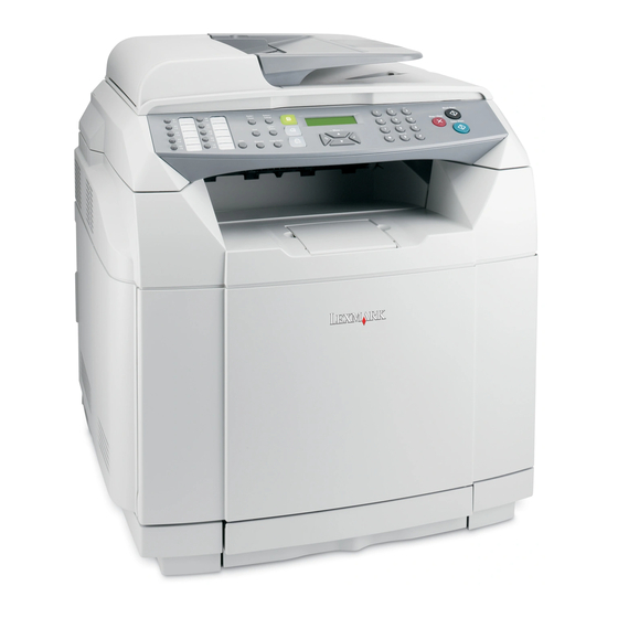
The Lexmark™ X500n and X502n are color laser MFPs that combine print, scan, copy, and fax functions. The X500n and X502n are the ideal MFPs for presentations, business graphics, line art, and text. They use laser diode electrophotographic technology to deliver remarkable quality print images and text. The scan and copy functions work with A4 , letter, and legal (ADF only) size paper. -
Page 22: Mfp Specifications
Macintosh OS X version 10.2–10.4 and above. (Power PC and Intel) The software applications that operate with most Apple LaserWriter printers will generally operate with this printer. Download the latest Lexmark printer PPD files or printer drivers from www.lexmark.com. Service Manual... - Page 23 • Microsoft Windows Vista 32/64 bit Download the latest printer drivers from http://www.lexmark.com. The Windows software applications, which operate in the operating systems listed above, are best suited to run with the drivers supplied with this MFP. The drivers for Windows take advantage of the MFP’s functions and increase the MFP’s performance wherever possible.
- Page 24 Rear 10 in (254 mm) 10 in (254 mm) 16 in (400 mm) 16 in (400 mm) Packaging and shipping dimensions Width Depth Height Weight MFP* X500n / X502n 23.4 22.6 29.9 42.0 Options 530-Sheet drawer 21.9 22.4 10.9 18.7...
- Page 25 7100-XXX Environment Environment Specifications Operating Air temperature–product operating 10 to 32.5°C (50 to 90.5°F) Air temperature–product power off 5 to 35°C (41 to 95°F) Air relative humidity 15 to 80% Altitude 0–2,500 m (0–8,200 ft.) Ship / Storage Temperature-printer and supplies 0 to 35°C (32 to 95°F) Relative humidity 10 to 90% RH...
-
Page 26: Print Engine Specifications
7100-XXX Print engine specifications Print engine resolution 600 x 600 dpi, 1200 x 600 dpi Color balance settings This MFP offers color balance control. It is a color correction option that allows you to increase or decrease the amount of toner going to the page for all four color planes. The scale ranges from -10 to +10. Emulations Raster Graphics (CMYK bi-tone JBIG Compressed) Print engine speed and performance... - Page 27 Capacity may vary and is subject to media specifications and MFP operating environment. The capacities listed are based on plain paper at 75 g/m Sources and capacities X500n / X502n Input sources Number of standard sources...
- Page 28 7100-XXX Media input types and weights Source Type Standard tray 530–Sheet tray MFP menu Item Legal tray Paper Paper type weight Paper Xerographic or bond 60–74 60–74 Plain paper Light (grain long) paper (16-19 lb) (16-19 lb) Xerographic or bond 75–120 75–120 Plain paper...
- Page 29 7100-XXX Media sizes Media sizes Dimensions Input Output 210 x 297 8.27 x 11.7 148 x 210 5.83 x 8.27 JIS B5 182 x 257 7.17 x 10.1 Letter 216 x 279.4 8.5 x 11 Legal 216 x 356 8.5 x 14 Executive 184.2 x 266.7 7.25 x 10.5...
-
Page 30: Scan Specifications
7100-XXX Scan specifications Resolution 1200 X 2400 dpi Scan size 216mm X 297 mm (flatbed), Window size 220mm X 300mm Scan depth 48 bits Lamp warm up time Less than 3 seconds More than 30% Depth of focus -2 mm to +2 mm Magnification Less than 0.5% Scanning... -
Page 31: Copy Specifications
7100-XXX Copy specifications Resolution 600 dpi X 600 dpi (flatbed), 600 X 300 dpi(ADF), Print from copy – 600 X 600 dp 9600 dpi X 9600dpi w/ software interpolation Original paper sizes A4, Letter, Legal (ADF only), B5 (JIS), Executive Copies per minute Mono: up to 21, Color: up to 7 Time to first copy... - Page 32 7100-XXX Document Sizes supported ADF width 5.5 to 8.5 inches (139.7 to 215.9 mm) ADF length 5.5 to 14 inches (139.7 to 355.6 mm) ADF capacity 35 sheets Flatbed width 8.5 inches (216 mm) Flatbed length 11.7 inches (297 mm) Scanning width 215.9 mm maximum Printing width...
-
Page 33: Media Guidelines
7100-XXX Media guidelines Paper designed for use with xerographic copiers should provide satisfactory print quality and feed reliability. Other media types may be suitable. We recommend that users test any particular brand for suitability to their applications. Refer to the MFP User's Guide for additional media specifications. Paper •... - Page 34 7100-XXX Labels • Labels should be selected using guidelines found in the User's Guide, Complete Printer Guide, or the Card stock & Label Guide (located at www.lexmark.com), and tested for acceptability. • Vinyl labels are not supported. • Labels are only supported in tray 1 (standard or legal trays).
-
Page 35: Maintenance Approach
7100-XXX Maintenance approach The diagnostic information in this manual leads you to the correct field replaceable unit (FRU) or part. Use the error code charts, symptom index, and service checks to determine the symptom and repair the failure. The removals in the repair information chapter may help you identify parts. •... -
Page 36: Serial Number
7100-XXX Serial number Look for serial number information on the right cover and the inside of the front cover of your MFP. Tools required for service The removal and adjustment procedures described in this manual require the following tools and equipment: •... -
Page 37: Acronyms
7100-XXX Acronyms Automatic document feeder ASIC Application specific integrated circuit BOOTP Boot protocol Charge coupled device DDNS Dynamic domain name service DHCP Dynamic host configuration protocol Dots per inch DRAM Dynamic random access memory Electrophotographic process Electrostatic discharge Field replaceable unit HTTP Hypertext transport protocol High voltage... - Page 38 7100-XXX 1-18 Service Manual...
-
Page 39: Diagnostic Information
7100-XXX 2. Diagnostic information Start CAUTION: Remove power from the printer before you connect or disconnect any cable, electronic board or assembly, for personal safety and to prevent damage to the printer. Always use the hand grips on the side of the printer and be sure your fingers are not under the printer when you set the printer down. -
Page 40: Understanding The Operator Panel
7100-XXX Understanding the operator panel Using the MFP menus Reports Print Machine Settings Copy Settings Configuration Page Speaker Volume Paper Select Activity Report Paper Settings Network Settings Sort Memory List Job Timeout Ethernet Density Quick Dial List Auto Continue IP Configuration Quality Speed Dial List Toner Saver Mode... -
Page 41: Service Error Codes
7100-XXX Service error codes Error code Action 001 Service Call Replace the RIP board. See “System board removal” on page 4-36. Or replace the engine controller board. See“Engine controller board removal” on System Board - CPU page 4-34. 002 Service Call System Board - Flash 003 Service Call System Board - DRAM... - Page 42 7100-XXX Error code Action E2 Service Call A NOT READY signal (rotation error signal) is detected because of abnormal main motor rotation. Main Motor “Main motor service check” on page 2-14. E3 Service Call Unstable transfer belt rotation—color matching cannot be secured. Transfer Belt Sensor “Transfer belt unit service check”...
- Page 43 7100-XXX Error code Action H4 Service Call Fusing temperature rises above limit during printing process and does not return within the alloted time period. Fuser Unit “Fuser assembly service check” on page 2-24. HA Service Call AC relay turned off due to an abnormal temperature. Fuser Unit “Fuser assembly service check”...
-
Page 44: User Status Messages
7100-XXX User status messages Message Description Action Tray (1, 2) Missing The upper or lower tray is install the upper or lower tray. If the problem missing. persists, see “Paper tray missing service check” on page 2-30. Toner Low (C,M,Y,K) The toner is low in the “Toner low/empty service check”... - Page 45 7100-XXX Message Description Action TAD Answering A telephone call is being These are the normal operating modes. received. Answering The fax is answering an in coming call. incoming Call There is an incoming call on the phone line Warming Up The MFP is warming up.
-
Page 46: User Attendance Messages
7100-XXX User attendance messages Message Description Action Paper Empty The upper or lower paper Fill up the paper tray(s) or replace the media with tray is empty or the media the correct type. If the problem persists, see (Load Tray - Paper Size, Load in the trays is inconsistent. - Page 47 7100-XXX Message Description Action Toner Error An invalid toner cartridge install a supported cartridge. If the problem is installed. persists, see “Missing toner cartridge service install Supported Cartridge check” on page 2-32. Missing A toner cartridge is not install proper brand of toner cartridge. If problem keyed properly.
- Page 48 7100-XXX Message Description Action Scan USB Disconnect The USB connection is “USB service check” on page 2-40. disconnected. Scan Network Disconnect The network connection is “Network service check” on page 2-40. disconnected. Duplicate IP Address Found Another device using an Contact the network administrator.
-
Page 49: Symptom Tables
7100-XXX Symptom tables MFP symptom table Symptom Action Paper feed problems “Paper feed service checks” on page 2-44. Close door displayed when all doors are closed. “User attendance messages” on page 2-8, and follow the action suggested. Paper jam messages do not reset after removing “User attendance messages”... - Page 50 7100-XXX Symptom Action No dial tone when sending a fax. “Modem / fax card service check” on page 2-43. Lines on outbound fax documents Check the flatbed glass for scratches or marks. Words and images on inbound fax documents are The sending machine had a temporary jam.
-
Page 51: Print Quality Symptom Table
7100-XXX Print quality symptom table Symptom Action Background “Background service check” on page 2-45. Missing image at edge “Missing image at edge service check” on page 2-53. Jitter “Jitter service check” on page 2-52. Ribbing “Ribbing service check” on page 2-57. -
Page 52: Printer Service Checks
7100-XXX Printer service checks Main motor service check Step Questions / actions Turn printer off and remove right cover. See Replace photodeveloper Go to step 2. “Right cover removal” on page 4-13. cartridge. Open top cover and override top cover interlock switch. - Page 53 7100-XXX Step Questions / actions Disconnect cable from engine controller Replace engine controller Replace cable that board POCN. Check the following on board. See “Engine connects ACN1 on LVPS to disconnected cable connector: controller board removal” POCN on engine controller on page 4-34.
-
Page 54: Cpu Fan Service Check
7100-XXX CPU fan service check Step Questions / actions Open the RIP cage cover. Is the CPU fan No issue to fix. Go to step 2. spinning? Is the CPU fan cable properly connected to Connect the cable to J- Replace the RIP board. -
Page 55: Transfer Belt Unit Service Check
7100-XXX Step Questions / actions Disconnect cable from engine controller Replace engine controller Replace cable that board POCN. Check the following on board. See “Engine connects ACN1 on LVPS to disconnected cable connector: controller board removal” POCN on engine controller on page 4-34. -
Page 56: Transfer Roller Clutch Service Check
7100-XXX Transfer roller clutch service check Step Questions / actions Turn printer off and remove printer right Go to step 2. Properly connect cable. If cover. See “Right cover removal” on problem persists, go to step page 4-13. Is cable properly connected to transfer roller clutch? Disconnect transfer roller clutch from cable. -
Page 57: Paper Feed Clutch Service Check
7100-XXX Paper feed clutch service check Step Questions / actions Turn printer off, and remove printer right Go to step 2. Properly connect cable. If cover. See “Right cover removal” on problem persists, go to step page 4-13. Is cable properly connected to paper feed clutch? Disconnect paper feed clutch from cable. -
Page 58: Opc Belt Marker Sensor Service Check
7100-XXX OPC belt marker sensor service check Step Questions / actions Remove photodeveloper cartridge and Go to step 2. Replace photodeveloper check for defects. Does photodeveloper cartridge. appear okay? Observe markers on side. Are belt markers Clean marker area with Go to step 3. -
Page 59: Erase Lamp Service Check
7100-XXX Erase lamp service check Step Questions / actions Turn printer off, and remove toner cartridges Go to step 2. Properly connect erase and photodeveloper cartridge. Check erase lamp. Retest printer. If error lamp cable for proper connection. Is erase clears, problem solved, lamp cable properly connected? otherwise go to step 2. -
Page 60: Power Supply Fan Service Check
7100-XXX Power supply fan service check Step Questions / actions Turn printer off, and remove engine Go to step 2. Properly connect cable. controller board shield. See “Engine controller board removal” on page 4-34 for steps to remove engine controller board shield. -
Page 61: High Voltage Power Supply (Hvps) Service Check
7100-XXX High voltage power supply (HVPS) service check Step Questions / actions Remove photodeveloper cartridge, Replace photodeveloper Go to step 2. and ensure charging unit on bottom cartridge. See of photodeveloper cartridge is not “Photodeveloper cartridge damaged. Is charging unit removal”... -
Page 62: Fuser Thermistor Service Check
7100-XXX Fuser thermistor service check Step Questions / actions Remove and reinstall fuser assembly. See Problem solved. Go to step 2. “Fuser assembly removal” on page 4-6. Does error clear? Check fuser connector for damage. Replace Problem solved. Go to step 3. if necessary. -
Page 63: Laser Unit Assembly Service Check
7100-XXX Laser unit assembly service check Step Questions / actions Check LCN connection on laser assembly Go to step 2. Properly connect LCN LDU board. Is connector properly cable. If error clears, connected? problem solved, otherwise go to step 2. Check LCN connection on engine controller Go to step 3. -
Page 64: Toner Empty Sensor (Sender-Tpd) Service Check
7100-XXX Toner empty sensor (sender-TPD) service check Step Questions / actions Turn printer off. and remove engine Go to step 2. Properly connect cable. controller board shield. See “Engine Retest printer. If error controller board removal” on page 4-34 clears, problem solved, for steps to remove engine controller board otherwise go to step 2. -
Page 65: Toner Empty Sensor (Receiver-Ttr) Service Check
7100-XXX Toner empty sensor (receiver-TTR) service check Step Questions / actions Turn printer off, and remove engine Go to step 2. Properly connect cable. controller board shield. See “Engine Retest printer. If error controller board removal” on page 4-34 clears, problem solved, for steps to remove engine controller board otherwise go to step 2. -
Page 66: Lower Feed Unit (Secondary Paper Assembly) Service Check
7100-XXX Lower feed unit (secondary paper assembly) service check Step Questions / actions Turn printer off, and remove engine Go to step 2. Properly connect cable. controller board shield. See “Engine Retest printer. If error controller board removal” on page 4-34 clears, problem solved, for steps to remove shield. -
Page 67: Tray Empty Service Check
7100-XXX Tray empty service check Step Questions / actions Remove paper tray from printer. Press Go to step 2. Replace paper tray. bottom of spring platform latches located in rear corners of paper tray. This releases spring platform of paper tray. Ensure tray is raising paper after insertion. -
Page 68: Paper Tray Missing Service Check
7100-XXX Paper tray missing service check Step Questions / actions Turn printer off, and remove engine Go to step 2. Properly connect cable. controller board shield. See “Engine controller board removal” on page 4-34 for steps to remove engine controller board shield. -
Page 69: Toner Low/Empty Service Check
7100-XXX Toner low/empty service check Step Questions / actions Turn printer off, and remove engine Go to step 2. Properly connect cable. controller board shield. See “Engine controller board removal” on page 4-34 for steps to remove engine controller board shield. -
Page 70: Missing Toner Cartridge Service Check
7100-XXX Missing toner cartridge service check Step Questions / actions Remove toner cartridge in question. Holding Replace toner cartridge. Go to step 2. toner cartridge with developer roller away from you, check toner present sensor actuators located on left rear of toner cartridge. -
Page 71: Missing Photodeveloper Cartridge Service Check
7100-XXX Missing photodeveloper cartridge service check Step Questions / actions Check photodeveloper cartridge for proper Go to step 2. install properly. installation. Is cartridge installed properly? Check printer contacts (A) and Replace photodeveloper Replace photodeveloper cartridge. See cartridge. See photodeveloper cartridge contacts (B) for “Photodeveloper “Photodeveloper dirt and damage. -
Page 72: Transfer Roller Missing Service Check
7100-XXX Transfer roller missing service check Step Questions / actions Turn printer off, and check transfer roller Go to step 2. If contact A has slipped off contacts. Are contacts present and not frame, put it back on. If you damaged? cannot see it, remove HVPS cage (see... -
Page 73: Cover Open Service Check
7100-XXX Cover open service check Step Questions / actions Turn printer off, and remove right cover. Go to step 2. Replace appropriate “Right cover removal” on page 4-13. actuator: Check all interlock switch (top, rear and Front cover for front cover front) actuators for proper operation. -
Page 74: Opc Belt (Photodeveloper) Cartridge Drive Service Check
7100-XXX OPC belt (photodeveloper) cartridge drive service check Step Questions / actions Check photodeveloper cartridge for proper Go to step 2. install properly. installation. Is cartridge installed properly? Check photodeveloper cartridge for Replace photodeveloper Go to step 3. cartridge. See damage. -
Page 75: Paper Size Sensing Service Check
7100-XXX Paper size sensing service check Step Questions / actions Turn printer off, and remove engine Go to step 2. Properly connect cable. controller board shield. See “Engine controller board removal” on page 4-34 for steps to remove engine controller board shield. -
Page 76: Printer No Power Service Check
7100-XXX Printer no power service check Note: If secondary paper feed assembly or duplex unit is installed, disconnect or remove before checking base printer operation. Step Questions / actions Reset printer, and listen for any activation of Go to step 2. Go to step 3. -
Page 77: Toner Feed Service Check
7100-XXX Toner feed service check Step Questions / actions Check toner cartridge for damage. Check to Replace toner cartridge. Go to step 2. see if toner cartridge moves easily into and out of printer. Is toner cartridge damaged or is there resistance moving in and out of printer? Is developer motor damaged? Replace developer drive... -
Page 78: Operator Panel Service Check
7100-XXX Operator panel service check Step Questions / actions Is the operator panel cable properly Go to step 2. Properly connect the cable connected to the op panel? to the op panel. Is the op panel cable properly connected to Go to step 3. -
Page 79: Black Page Copy Service Check
7100-XXX Scanner / Copy / Fax service checks Black page copy service check Step Questions / actions Print a menu page, or a page from the host. “High voltage power Go to step 2. Is the page black? supply (HVPS) service check”... -
Page 80: Adf Paper Feed Service Check
7100-XXX ADF paper feed service check Step Questions / actions If the ADF is multi-feeding, check for dirt on Clean them with a lint free Replace the separator pad the ADF separator pad and ADF separator cloth and isopropyl alcohol. and ADF pick roll. -
Page 81: Modem / Fax Card Service Check
7100-XXX Modem / fax card service check Step Questions / actions Is the phone line properly connected to the Go to step 2. Properly connect the phone modem card and the wall jack? line to the modem card and wall jack. Is the modem card cable properly Go to step 3. -
Page 82: Paper Feed Service Checks
7100-XXX Paper feed service checks Printer paper feed service check Problem area Action Check for recommended paper Ensure paper being used is recommended. Ensure paper is stored in an area free from high humidity. Note: Disconnect secondary paper assembly, if installed, to help isolate a paper transport problem. -
Page 83: Print Quality Service Checks
7100-XXX Print quality service checks Background service check Background is smeared due to toner spread. Problem area Action Toner cartridge Too small charging amount in the development process. Check developer high voltage contact points. insufficient contact of developer roller's primary or secondary high voltage contact points. -
Page 84: Back Stain Service Check
7100-XXX Back stain service check Backside of paper is stained. Problem area Action Fuser assembly • Fuser roller and back-up roller are stained. • Fusing offset error occurred. Replace fuser assembly. See “Fuser assembly removal” on page 4-6. Note: Fuser assembly is a customer-ordered supply. Transfer roller Transfer roller is stained. -
Page 85: Banding Service Check
7100-XXX Banding service check A banding line appears in horizontal direction. Problem area Action Photodeveloper (OPC) cartridge Transfer failure due to uneven rotational speed caused by a shock which occurs when the seam of the OPC belt passes over the cleaning blade. Replace photodeveloper cartridge. -
Page 86: Black Line Service Check
7100-XXX Black line service check A fine black line appears in printer image. Problem area Action Toner cartridge Toner cartridge blade is deformed. Replace toner cartridge. Photodeveloper (OPC) cartridge OPC belt surface is damaged. Replace photodeveloper cartridge. See “Photodeveloper cartridge removal” on page 4-8. -
Page 87: Color Misregistration Service Check
7100-XXX Color misregistration service check Color misregistration between two colors. Problem area Action Transfer roller and transfer belt cleaning roller Transfer belt fails to maintain regular and proper rotation due to impact caused when transfer roller or transfer belt cleaning roller contacts transfer belt. -
Page 88: Insufficient Fusing Service Check
7100-XXX insufficient fusing service check Printed image is partially missing. Problem area Action Fuser tension release lever Fuser tension release lever is open. Check fuser, and remove shipping pieces if still installed. Close release lever. Driver media settings Driver media setting is wrong. Ensure proper media setting is selected for specific media in use. -
Page 89: Insufficient Gloss Service Check
7100-XXX insufficient gloss service check Gloss on paper is not sufficient. Problem area Action Driver media settings Driver media setting is wrong. Ensure proper media setting is selected for specific media in use. Fuser Fuser roller is deteriorated. Fuser temperature is not properly controlled. Replace fuser. -
Page 90: Jitter Service Check
7100-XXX Jitter service check Uneven optical density appears periodically in horizontal direction. Problem area Action Photodeveloper cartridge Replace faulty photodeveloper cartridge. See “Photodeveloper cartridge removal” on page 4-8. Note: Photodeveloper cartridge is a customer order supply. Main motor assembly • Irregular rotation of main motor assembly •... -
Page 91: Missing Image At Edge Service Check
7100-XXX Missing image at edge service check Image has missing or peeling toner at edge. Problem area Action Toner cartridge Too small a toner mass amount and charging amount in the development process. Replace toner cartridge. Photodeveloper cartridge OPC belt is deformed and wavy. Replace photodeveloper cartridge. -
Page 92: Mixed Color Image Service Check
7100-XXX Mixed color image service check Mixed color image appears. Problem area Action Toner cartridge Ensure toner cartridge moves in and out of printer without a lot of resistance. Compare toner cartridge in question with one of the other known working cartridges. Replace toner cartridge if defective. -
Page 93: Mottle Service Check
7100-XXX Mottle service check Variation of optical density is found in image. Problem area Action Rear cover assembly Rear cover assembly is not fixed in place. Open rear cover assembly, and close properly. Transfer roller Transfer roller is not properly installed. Remove and reinstall transfer roller. -
Page 94: Residual Image Service Check
7100-XXX Residual image service check Image of preceding page appears on every other page. Problem area Action Transfer unit cleaning roller Cleaning roller is not installed properly. Remove and reinstall. Ensure left side of cleaning roller is making good contact with HVPS contact. -
Page 95: Ribbing Service Check
7100-XXX Ribbing service check Light print occurs in right or left side of image. Problem area Action Printer is not level Table printer is sitting on is slightly tilted. Tilt should be less than 1/2 inch. Confirm the printer table is large enough and the printer is level. -
Page 96: Smear Service Check
7100-XXX Smear service check The entire image appears smudged. Problem area Action Photodeveloper cartridge (OPC belt) and This print quality issue is usually accompanied by a paper transfer belt jam. Remove the photodeveloper cartridge, and check for a piece of paper on the rear side of the photodeveloper cartridge. -
Page 97: Toner Drop Service Check
7100-XXX Toner drop service check A toner spot stain on paper is caused by ambient toner within printer engine. Problem area Action Waste toner feed system Toner drops on the transfer drum due to a breakdown of the waste toner feed system. •... -
Page 98: Vertical Line Service Check
7100-XXX Vertical line service check A vertical line appears in printed image. Problem area Action Photodeveloper cartridge (OPC belt) and Foreign particles (dust and so on) adhere to parts located transfer belt around photodeveloper cartridge and transfer belt unit which consequently contact toner image on transfer belt unit. -
Page 99: Vertical Staggering Image Service Check
7100-XXX Vertical staggering image service check Printed image staggers in vertical direction. Problem area Action Printer vibration Check for printer vibrations or shock to printer. Laser unit assembly (printhead) Optical unit failure caused by vibration from scanner motor rotation. Replace laser unit assembly. See “Upper right rear cover removal”... -
Page 100: Vertical White Band Service Check
7100-XXX Vertical white band service check White band appears in vertical direction of printed image. Problem area Action Toner cartridge Replace faulty toner cartridge. Photodeveloper cartridge Replace faulty photodeveloper cartridge. See “Photodeveloper cartridge removal” on page 4-8. Transfer belt unit Replace faulty transfer belt unit. -
Page 101: White Band Service Check
7100-XXX White band service check Horizontal white banding creates missing portion of image. Problem area Action Transfer roller • Transfer roller bias pole is not making proper contact with high voltage spring contact. Remove and reinstall transfer roller. Ensure spring contact on left side (looking from front of printer) is not damaged. -
Page 102: White Line I Service Check
7100-XXX White line I service check Vertical white line appears in a specific color area when print quality test print is run. Problem area Action Test print Print the maintenance page. See “Printing the maintenance and configuration pages” on page 3-3. -
Page 103: White Spot / Black Spot Service Check
7100-XXX White spot / black spot service check A white spot and black spot appear on paper. Problem area Action Photodeveloper cartridge There are foreign particles adhering to photodeveloper OPC belt. Remove photodeveloper cartridge (see “Photodeveloper cartridge removal” on page 4-8). -
Page 104: White Print Service Check
7100-XXX White print service check Blank page (no print at all) is printed or, a specific color is missing. Problem area Action Solid white print Optical Unit (Printhead) Laser light path is blocked by paper or other material stuck at the opening of the optical unit. -
Page 105: Wrinkle / Image Migration Service Check
7100-XXX Wrinkle / image migration service check Banding shadows of different optical density appear due to wrinkle, image migration, and color misregistration occurring on paper. Problem area Action Non-recommended paper Paper being used is not recommended for printer. Replace paper with recommended paper. Rear cover assembly Open rear cover assembly and reclose, ensuring that both sides properly latch. -
Page 106: Uneven Density (Right And Left)
7100-XXX Uneven density (right and left) Optical density is different between right and left side of printed image. Problem area Action Rear cover assembly Open rear cover assembly and reclose, ensuring that both sides properly latch. If rear cover assembly will not properly latch, ensure that white door actuators located at top of rear cover assembly are not damaged. -
Page 107: Spacing Table
7100-XXX Spacing table Roller specifications Repeating defect on Diameter Number of rotations Name of roller print (mm) (rpm) (mm) Registration assembly rubber roller ø 14 Registration assembly steel roller ø 12 Transfer roller ø 20 Developer roller ø 18 Transfer belt drive roller (part of transfer ø... - Page 108 7100-XXX 2-70 Service Manual...
-
Page 109: Diagnostic Aids
Lexmark confidential until announce edited 1/4/2007 7100-XXX 3. Diagnostic aids This chapter explains the tests and procedures to identify MFP failures and to verify repairs have corrected the problem. Understanding the MFP operator panel The use of the buttons and the layout of the operator panel is described in the following table. - Page 110 7100-XXX Lexmark confidential until announce edited 1/4/2007 Number Button Function Reduce / Enlarge Copy mode - Reduce or enlarge the image data to a copy job. Scan mode - Select the push scan document size. Lighter / Darker Copy mode - Adjust the copy exposure (5 levels available).
-
Page 111: Retrieving, Printing And Restoring The Mfp Settings
Lexmark confidential until announce edited 1/4/2007 7100-XXX Retrieving, printing and restoring the MFP settings Printing the maintenance and configuration pages Before replacing the engine controller board or the system / RIP board, print out the maintenance and configuration pages. These page contain the MFP setting information that will need to be reset on the new board. -
Page 112: Maintenance Mode
7100-XXX Lexmark confidential until announce edited 1/4/2007 Maintenance mode Maintenance mode contains information and settings that can be used in servicing the X5xx series MFPs. The maintenance mode menu is entered by holding down the key when performing a POR. The various... -
Page 113: Print Reports
Lexmark confidential until announce edited 1/4/2007 7100-XXX Counter The Counter submenu displays various counters maintained by the MFP. These are permanent counts. While in the Display info menu, use the keys to navigate to Counter and press the key to enter the submenu. -
Page 114: Engine Maintenance
7100-XXX Lexmark confidential until announce edited 1/4/2007 Engine maintenance This submenu shows the replacement status of the various maintenance items on the MFP. From the top level of the Maintenance mode menu, use the keys to navigate to Engine Maintenance. Press to select the Engine Maintenance item. - Page 115 Lexmark confidential until announce edited 1/4/2007 7100-XXX Protocol Definition The two submenu items can be accessed using the keys to navigate to the individual settings. When the desired protocol definition setting is displayed, press to select the item. Training Retries — This is the number of attempts made to receive a fax before switching to a different compression setting.
-
Page 116: Density Tune Up
7100-XXX Lexmark confidential until announce edited 1/4/2007 Density Tune Up These settings adjust the density of the separate color planes for the copy, scan, and fax functions. These settings should not be adjusted without second-level support center supervision. The density tune-up menu items can be accessed using the keys to navigate to the individual settings. -
Page 117: Printer Theory Of Operation
We will discuss the Lexmark X500n MFP and its particular method of printing. EP Basics The Lexmark X500n is a single laser MFP that uses four toner cartridges (Cyan, Yellow, Magenta and Black) to create text and images on media. The MFP has one photodeveloper (called a photodeveloper cartridge or OPC) and a transfer Unit. -
Page 118: Summary Of The Ep Process On The X500
7100-XXX Lexmark confidential until announce edited 1/4/2007 Summary of the EP process on the X500 This graphic illustrates the steps of the EP process on the X500 3-10 Service Manual... -
Page 119: X500 Ep Steps In Detail
Lexmark confidential until announce edited 1/4/2007 7100-XXX X500 EP steps in detail Step 1: Charge During the charge step, voltage is sent from the high voltage power supply to the charge roller inside the photodeveloper. The charge roller is part of the photodeveloper unit. - Page 120 7100-XXX Lexmark confidential until announce edited 1/4/2007 Step 2: Expose During the expose step, the laser fires a focused beam of light at the surface of the photodeveloper and writes an invisible image called a latent image or electrostatic image. This is repeated for each color printed.
- Page 121 Lexmark confidential until announce edited 1/4/2007 7100-XXX Step 3: Develop Once the laser exposes the photodeveloper, the high voltage power supply sends a charge to the developer roller. The first toner cartridge engages the photodeveloper so it is in contact with the surface. Because of the charge difference between the toner on the developer roller and the electrostatic image created by the laser, the toner will cling to the OPC.
- Page 122 7100-XXX Lexmark confidential until announce edited 1/4/2007 Step 4: Transfer First transfer After the first plane of color is developed on the photodeveloper, the high voltage power supply sends voltage to the transfer unit so the image on the photodeveloper is transferred to the transfer unit. This takes place by a direct surface-to-surface contact between the photodeveloper and the transfer unit.
- Page 123 Lexmark confidential until announce edited 1/4/2007 7100-XXX Second transfer Once the last plane of color is transferred to the transfer unit from the photodeveloper, media is picked from the paper tray and carried to the transfer roller. The transfer unit continues to rotate around and meets the paper at the Transfer Roller area.
- Page 124 7100-XXX Lexmark confidential until announce edited 1/4/2007 Step 5: Fuse Once the image has been fully transferred to the media, the transfer roller helps move the paper into the fuser area. The fuser applies heat and pressure to the page to melt the tiny toner particles and bond them permanently to the media.
- Page 125 Lexmark confidential until announce edited 1/4/2007 7100-XXX Step 6: Clean/Erase There are two main cleaning processes that take place during the EP Process. One process cleans the photodeveloper and the other cleans the transfer unit. Photodeveloper clean/erase After each plane of color has been transferred to the transfer unit from the photodeveloper, a cleaning blade scrapes the remaining toner from the surface of the photodeveloper while an erase lamp discharges the remaining voltage.
- Page 126 7100-XXX Lexmark confidential until announce edited 1/4/2007 Transfer unit cleaning Once the toner image on the transfer unit has been transferred to the page, the transfer unit rotates around and is cleaned by the cleaning roller. This cleaning happens after each page is printed.
-
Page 127: Printer Components
Lexmark confidential until announce edited 1/4/2007 7100-XXX Printer Components The following graphic illustrates all the EP and paper transport processes in the X500 3-19 Diagnostic aids... -
Page 128: Paper Path Components
X500n specific information The Lexmark X500n has a simple “C” shaped paper path (see the picture below). The tray 1 paper path is shown in red, and the optional tray 2 path is shown in blue (Tray 2 is not shown). - Page 129 Lexmark confidential until announce edited 1/4/2007 7100-XXX Transport Components In summary, as shown in the previous illustration, the media is fed from the paper tray into the printer by a feed roller which carries the media to the registration rollers. The media trips the registration sensor. At this point, the media pauses so the registration rollers can properly time the media entry to the EP process.
-
Page 130: Paper Jam Messages
7100-XXX Lexmark confidential until announce edited 1/4/2007 Paper jam messages The following illustration lists paper jam messages indicating where the paper jam occurred. CAUTION When clearing paper jams, inside of the printer may be hot. Allow printer to cool before touching any internal components. -
Page 131: Accessing Jam Areas
Lexmark confidential until announce edited 1/4/2007 7100-XXX Accessing jam areas Open doors and covers, and remove trays to access jam areas. The illustration shows the location of sources and possible jam areas. Use the following table to locate instructions for a particular jam; however, to resolve any message, you must clear all media from the media path. -
Page 132: Paper Jam A1, Rear (Tray 1)
7100-XXX Lexmark confidential until announce edited 1/4/2007 Paper Jam A1, rear (tray 1) A PAPER JAM-A1 message indicates the media is jammed in tray 1. To clear a jam from the standard tray (Tray 1): 1. Pull the tray out. Remove the tray completely. - Page 133 Lexmark confidential until announce edited 1/4/2007 7100-XXX • For media jammed behind the tray area, locate the jam on the bottom surface of the tray housing. You may have to reach far under the printer to locate the jam, as shown in the following illustration.
-
Page 134: Paper Jam A2, Rear (Tray 2)
7100-XXX Lexmark confidential until announce edited 1/4/2007 Paper Jam A2, rear (tray 2) A PAPER JAM-A2 message indicates the media is jammed in tray 2. To clear a jam from the optional 530- sheet tray (Tray 2): 1. Pull the tray out. Remove the tray completely. -
Page 135: Paper Jam B Rear
Lexmark confidential until announce edited 1/4/2007 7100-XXX Paper Jam B rear CAUTION When clearing paper jams, inside of the printer may be hot. Allow printer to cool before touching any internal components. A PAPER JAM-B message indicates the media is jammed behind the rear door. To clear this type of jam, do the following: 1. - Page 136 7100-XXX Lexmark confidential until announce edited 1/4/2007 3. Pull the fuser pressure release levers to release tension on the media. 4. Grasp each side of the jammed media. Pull it to the rear of the printer and then out. Note: Gently pull the media out so you do not tear it.
-
Page 137: Paper Jam C Rear
Lexmark confidential until announce edited 1/4/2007 7100-XXX Paper Jam C rear A PAPER JAM-C message indicates the media is jammed behind the rear door above the fuser. 1. Push the rear door release latch, and gently lower the rear door. -
Page 138: Adf Paper Jams
7100-XXX Lexmark confidential until announce edited 1/4/2007 ADF paper jams An ADF JAM: Open ADF Cover and Clear Jam message indicates a jam in the ADF. WARNING: Do not clear any ADF jams until the release lever on the ADF pick roller assembly is opened. - Page 139 Lexmark confidential until announce edited 1/4/2007 7100-XXX To clear an ADF paper jam, follow these steps. 1. Open the ADF top cover. 2. Lift the green separator roll release lever to the up position. Do not remove the separator roll.
- Page 140 7100-XXX Lexmark confidential until announce edited 1/4/2007 4. Lower the separator roller release lever until it locks in place. 5. Close the ADF cover, and test the ADF. 3-32 Service Manual...
-
Page 141: Repair Information
7100-XXX 4. Repair information Removal and cleaning precautions Observe the following precautions whenever you service the MFP: • Prior to starting any repair, read and understand the warnings in this manual. • Be sure to unplug the MFP from the outlet before attempting to service the MFP. •... -
Page 142: Handling Esd-Sensitive Parts
7100-XXX Handling ESD-sensitive parts Many electronic products use parts that are known to be sensitive to electrostatic discharge (ESD). To prevent damage to ESD-sensitive parts, follow the instructions below in addition to all the usual precautions, such as turning off power before removing logic cards: •... -
Page 143: Photodeveloper Cartridge
7100-XXX Photodeveloper cartridge The following precautions must be observed when handling the photodeveloper cartridge or commonly called OPC (optical photo conductor). The photodeveloper cartridge is a supply item you will have to remove during some of the repair procedures: During transportation/storage Use the specified carton whenever moving or storing the photodeveloper cartridge. -
Page 144: Mfp Removals
7100-XXX MFP removals There are FRU/CRUs and supply items that will need to be removed prior to some of the removal procedures. The removal procedure will specify when the part must be removed. Cleaning roller cover removal 1. Raise the scanner unit. 2. -
Page 145: Transfer Belt Unit Removal
7100-XXX Transfer belt unit removal 1. Open the rear cover assembly. 2. Rotate the two captive screws (A) counterclockwise until they are loose. Warning: Take great care when removing the transfer belt unit to prevent scratching the transfer belt. Do not touch or hit the belt during removal. -
Page 146: Transfer Roller Removal
7100-XXX Transfer roller removal 1. Open the rear cover assembly. 2. Rotate the transfer roller to release; lift and remove. Fuser assembly removal 1. Push the rear cover assembly latch, and lower the rear cover assembly. 2. Turn two green fuser release levers (A). Service Manual... -
Page 147: Waste Toner Bottle Removal
7100-XXX 3. Lift the fuser straight up and away from the MFP. Waste toner bottle removal 1. Open the front cover. 2. Remove the waste toner bottle. Warning: Ensure that the waste toner bottle is secured and not allowed to tip over during repair process. Failure to adhere to this warning may result in toner spillage. -
Page 148: Photodeveloper Cartridge Removal
7100-XXX Photodeveloper cartridge removal Warning: Follow precautionary procedures (see “Photodeveloper cartridge” on page 4-3) when removing the photodeveloper cartridge. 1. Raise the scanner assembly. 2. Open the top cover assembly. 3. Depress the release levers (A). 4. Lift and remove the photodeveloper cartridge. 5. -
Page 149: Secondary Paper Feed Assembly Removal
7100-XXX Secondary paper feed assembly removal 1. Remove the left secondary paper feed assembly cover. Repeat for the right side. 2. Loosen the thumbscrew (A) on the left bracket, and remove the bracket. Repeat for the right side. 3. With help from another person, lift the MFP by the recessed handholds and remove the MFP from the secondary paper feed assembly. -
Page 150: Cover Removals
7100-XXX Cover removals Top cover assembly removal 1. Remove the scanner assembly. See “Flatbed assembly removal” on page 4-49. 2. Remove the upper right rear cover. See “Upper right rear cover removal” on page 4-17. 3. Remove the cleaning roller cover. See “Cleaning roller cover removal”... - Page 151 7100-XXX Remove the screw (B) which secures the top cover to the MFP frame. 10. Remove the upper left rear cover. See “Upper left rear cover removal” on page 4-17. 11. Remove the screw (C) which secures the top cover to the MFP frame. 12.
-
Page 152: Front Cover Assembly Removal
7100-XXX Front cover assembly removal 1. Open the front cover assembly. 2. Remove the 8 screws (A) from the inner front cover. 3. Disengage the support strap from the MFP. 4. Release the tabs on the front cover. 5. Remove the front cover from the inner front cover. 6. -
Page 153: Right Cover Removal
7100-XXX 7. Rotate the support pin away from the MFP, and slide toward the center of the MFP to remove. Repeat for the other support pin 8. Remove the front inner cover from the MFP. Right cover removal 1. Remove the waste toner bottle. See “Waste toner bottle removal”... -
Page 154: Rear Cover Assembly Removal
7100-XXX Rear cover assembly removal 1. Remove the fuser assembly. See “Fuser assembly removal” on page 4-6. 2. Remove the transfer belt unit. See “Transfer belt unit removal” on page 4-5. 3. Remove the right cover. See “Right cover removal” on page 4-13. -
Page 155: Left Front Cover Removal
7100-XXX Left front cover removal 1. Remove the top cover assembly. See “Top cover assembly removal” on page 4-10. 2. Remove two screws (A) from the bottom of the left front cover. 3. Remove the left cover from the MFP. 4-15 Repair information... -
Page 156: Left Rear Cover Removal
7100-XXX Left rear cover removal 1. Remove the screw (A) that secures the left rear cover to frame. 2. Slide the left rear cover back, and remove it from the printer. 4-16 Service Manual... -
Page 157: Upper Right Rear Cover Removal
7100-XXX Upper right rear cover removal 1. Open the rear cover. See “Rear cover assembly removal” on page 4-14. 2. Remove the screw (A) that secures the upper right rear cover to the frame. 3. Remove the upper right rear cover. Upper left rear cover removal 1. -
Page 158: Laser Unit Assembly (Printhead) Removal
7100-XXX Laser unit assembly (printhead) removal 1. Open the front cover. 2. Remove the toner cartridges. 3. Remove the photodeveloper cartridge. See “Photodeveloper cartridge removal” on page 4-8. 4. Open the top cover assembly. 5. Remove the two screws (A) from the laser unit assembly cover. The photograph below is looking through the opening in the top cover assembly. - Page 159 7100-XXX 7. Remove four screws (B) from the laser unit assembly. 8. Remove the laser unit assembly from the MFP. 9. Disconnect the connector from the laser unit assembly. 4-19 Repair information...
-
Page 160: Erase Lamp Removal
7100-XXX Erase lamp removal 1. Remove all the toner cartridges. 2. Remove the photodeveloper cartridge. See “Photodeveloper cartridge removal” on page 4-8. 3. Remove the transfer belt unit. See “Transfer belt unit removal” on page 4-5. 4. Remove the two screws (A). 5. -
Page 161: Right Side Removals
7100-XXX Right side removals Front door interlock switch with bracket 1. Remove the top cover assembly. See “Top cover assembly removal” on page 4-10. 2. Remove the right cover. See “Right cover removal” on page 4-13. 3. Disconnect the interlock switch cable (A) from the interlock switch. 4. -
Page 162: Waste Toner Bottle Holder Removal
7100-XXX Waste toner bottle holder removal 1. Remove the right cover. See “Right cover removal” on page 4-13. 2. Disconnect the waste toner bottle holder connector (A). 3. Remove three screws (B) from the waste toner bottle holder. The bottom screw is longer than the other screws. - Page 163 7100-XXX 4. Disconnect the developer driver assembly cables (B). 5. Remove the four screws (C) from the developer drive assembly. 6. Remove the developer drive assembly from the MFP. 4-23 Repair information...
-
Page 164: Toner Sensor (Sender) Removal
7100-XXX Toner sensor (sender) removal 1. Remove the developer drive assembly. See “Developer drive assembly removal” on page 4-22. 2. Remove two screws (A) from the toner sensor. Note: The bottom screw is longer than the top screw. 3. Pull the toner sensor away from the MFP, disconnect the cable, and remove the sensor. 4-24 Service Manual... -
Page 165: Cleaning Roller Clutch Removal
7100-XXX Cleaning roller clutch removal 1. Remove the transfer belt cleaning roller. See “Transfer belt cleaning roller removal” on page 4-4. 2. Remove the right cover. See “Right cover removal” on page 4-13. 3. Using a flat-tipped tool, pry and remove the cleaning roller clutch gear from the inside of the MFP. 4. -
Page 166: Main Motor Assembly Removal
7100-XXX Main motor assembly removal 1. Remove the right cover. See “Right cover removal” on page 4-13. 2. Disconnect the main motor assembly cable (A) from the main motor. 3. Remove 4 screws (B) from the main motor assembly. 4. Remove the main motor assembly from the MFP. 4-26 Service Manual... -
Page 167: Clutch Removal
7100-XXX Clutch removal Note: This procedure applies to the transfer roller clutch, registration clutch, and the paper feed clutch. The transfer clutch removal is shown. This removal is typical for the others. 1. Remove the right cover. See “Right cover removal” on page 4-13. -
Page 168: Waste Toner Feeder Removal
7100-XXX 6. Remove five screws (A) that secure the main drive gear assembly to the MFP. Note: screw shown removed. 7. Remove two screws (B) that secure the lower right frame. 8. Remove the main drive gear assembly from the MFP. Note: When reinserting the main drive gear assembly, ensure that the bottom right corner is installed before the lower right frame. - Page 169 7100-XXX 3. Remove screw (B) from the waste toner feeder pipe. 4. Remove the waste toner feeder pipe from the waste toner bottle holder. 5. Pull and remove the waste toner feeder from the MFP. 4-29 Repair information...
-
Page 170: Rear Removals
7100-XXX Rear removals Bracket assembly removal 1. Remove the erase lamp. See “Erase lamp removal” on page 4-20. 2. Remove two screws (A). 3. Disconnect connector (B) from the transfer belt marker sensor. 4. Disconnect connector (C) from the toner density sensor. 5. -
Page 171: Paper Guide Assembly Removal
7100-XXX Paper guide assembly removal 1. Remove the registration assembly. See “Registration assembly removal” on page 4-33. 2. Remove two screws (A) that attach the paper guide assembly to the MFP. Screws are located in holes. 3. Lift and remove the paper guide assembly (B) from the MFP. Paper guide C assembly removal 1. -
Page 172: Paper Feed Roller Removal
7100-XXX Paper feed roller removal 1. Remove the paper guide C assembly. See “Paper guide C assembly removal” on page 4-31. 2. Slide the paper feed roller off the shaft to remove. Paper exit assembly removal 1. Remove two screws (A). 4-32 Service Manual... -
Page 173: Registration Assembly Removal
7100-XXX 2. Disconnect the cable (B). 3. Remove two screws (C). Registration assembly removal 1. Remove the transfer roller. See “Transfer roller removal” on page 4-6. 2. Remove three metal screws (A) and three plastic screws (B). 3. Lift and remove the registration assembly. 4-33 Repair information... -
Page 174: Left Side Removals
7100-XXX Left side removals Engine controller board removal Warning: Before replacing the engine controller board, save the onboard settings. See “Printing the maintenance and configuration pages” on page 3-3. 1. Remove the left front cover. See “Left front cover removal” on page 4-15. - Page 175 7100-XXX 4. Disconnect all the connectors from the engine controller board. 5. Remove five screws (B) from the engine controller board; remove the engine controller board. Note: When reinstalling flat cables, ensure that the blue side of the cable is opposite of the pins on the connectors.
-
Page 176: System Board Removal
7100-XXX System board removal CAUTION There is a lithium battery on your system board. RISK OF EXPLOSION IF REPLACED BY AN INCORRECT TYPE. The battery is non-replaceable. Do not replace, recharge, disassemble, or incinerate a lithium battery. Discard used batteries according to the country, state or local regulations. - Page 177 7100-XXX 5. Remove the screw (B) securing the two ground wires. 6. Disconnect all the cables from the system board. 7. Remove two screws (C) securing the system board to the system board cage. 8. Slide the system board out of the MFP. 4-37 Repair information...
-
Page 178: System Board Cage Removal
7100-XXX System board cage removal 1. Remove the left front cover. See “Left front cover removal” on page 4-15. 2. Remove the three screws (A) securing the engine card shield. 3. Remove the engine card shield. 4. Disconnect all the cables from the engine card. 5. -
Page 179: High Voltage Power Supply (Hvps) Removal
7100-XXX High voltage power supply (HVPS) removal 1.Remove the RIP board cage. See “System board cage removal” on page 4-38. 2.Disconnect all the connectors from the HVPS. Note: When reinstalling flat cables, ensure that the blue side of the cable is opposite of the pins on the connectors. -
Page 180: Low Voltage Power Supply (Lvps) With Cage Removal
7100-XXX Low voltage power supply (LVPS) with cage removal 1. Remove the transfer belt unit. See “Transfer belt unit removal” on page 4-5. 2. Remove the RIP board cage. See “System board cage removal” on page 4-38. 3. Remove the grounding terminal screw (A). 4. -
Page 181: Hvps Cage Removal
7100-XXX HVPS cage removal 1. Remove the HVPS. See “High voltage power supply (HVPS) removal” on page 4-39. 2. Remove the LVPS with cage. See “Low voltage power supply (LVPS) with cage removal” on page 4-40. 3. Remove three screws (A); remove the HVPS cage. Toner present sensor removal 1. -
Page 182: Toner Sensor (Receiver) Removal
7100-XXX Toner sensor (receiver) removal Note: The toner sensor is comprised of two separate parts: the sender and the receiver. The sender portion of the toner sensor is located on the right side of the MFP. See “Toner sensor (sender) removal” on page 4-24 for removal. -
Page 183: Modem Speaker Removal
7100-XXX 5. Slide the left tray guide assembly out in front of the MFP. Modem speaker removal 1. Remove the left rear cover. 2. Remove the top cover. 3. Disconnect the modem speaker cable from the system / RIP board. 4. - Page 184 7100-XXX 5. Disconnect the fuser fan cable from the connector (B) behind the interlock assembly. 6. Remove the top screw (C) that secures the system board cage to the printer frame. 7. Remove the three screws (D) that secure the fuser fan assembly to the printer engine frame. 8.
-
Page 185: Modem Card Removal
7100-XXX Modem card removal 1. Remove the rip cage cover. 2. Disconnect the 30-pin cable (A) from the modem card. 3. Remove the screws (B) that secure the modem to the RIP cage. 4. Remove the modem. 4-45 Repair information... -
Page 186: Top Removals
7100-XXX Top removals Marker sensor assembly removal 1. Remove all the toner cartridges. 2. Remove the photodeveloper cartridge. See “Photodeveloper cartridge removal” on page 4-8. 3. Remove the transfer belt unit. See “Transfer belt unit removal” on page 4-5. 4. Remove screw (A) from the bracket. 5. -
Page 187: Waste Toner Auger Removal
7100-XXX Waste toner auger removal 1. Remove the photodeveloper cartridge. See “Photodeveloper cartridge removal” on page 4-8. 2. Remove the transfer belt unit. See “Transfer belt unit removal” on page 4-5. 3. Remove the top cover assembly. See “Top cover assembly removal” on page 4-10. -
Page 188: Power Supply Fan Removal
7100-XXX Power supply fan removal 1. Remove the top cover assembly. See “Top cover assembly removal” on page 4-10. 2. Disconnect the modem speaker cable from the system board, and carefully route the cable through the engine board cage. 3. Remove screw (A) from the power supply fan. 4. -
Page 189: Scanner Assembly Removals
7100-XXX Scanner assembly removals Flatbed assembly removal 1. Remove the left rear cover. See “Left rear cover removal” on page 4-16. 2. Remove the RIP/System board cover. See “System board removal” on page 4-36. 3. Open the MFP rear cover. 4. - Page 190 7100-XXX 7. Route all the cables through the RIP cage and around the fuser fan. 8. Remove the ribbon cable guide from the ribbon cable and flatbed unit. 9. Remove the four screws (C) that attach the flatbed to the scanner arms. 4-50 Service Manual...
- Page 191 7100-XXX 10. Tilt the scanner assembly vertically, carefully pulling the white slides off of the flatbed. 11. Lift the flatbed assembly off of the printer engine base. 4-51 Repair information...
-
Page 192: Scanner Arm Removal
7100-XXX Scanner arm removal 1. Remove the flatbed assembly. See “Flatbed assembly removal” on page 4-49. 2. Remove the screw (A) securing the scanner armlock to the printer top cover. 3. Tilt the top of the scanner arm to the center of the MFP, and remove the armlock (B). Note: Save the armlock for the new scanner arm. -
Page 193: Adf Unit Removal
7100-XXX 6. Repeat steps 3, 4, and 5 for the other arm, if needed. Note: If you are replacing the scanner arm, remove the spring from the old scanner arm. The spring will go on the new arm. ADF unit removal 1. - Page 194 7100-XXX 6. Remove the ADF cable cover from the rear of the flatbed unit. 7. Route the ADF cable and ADF ground wire through the RIP cage and flatbed unit. 8. Lift the flatbed cover to a vertical position, and up from the flatbed. 4-54 Service Manual...
-
Page 195: Adf Mechanism Cover Removal
7100-XXX 9. With a flat-blade screwdriver, press against the tab on the ADF unit retainer. 10.Lift the ADF unit up and away from the flatbed unit. Note: Remove the ADF paper tray from the old ADF unit. It will be used on the new ADF unit. ADF mechanism cover removal 1. - Page 196 7100-XXX 4. Remove the ADF front cover. 5. Remove the screw (B) which secures the ADF separator roll lock to the ADF. 6. Remove the ADF separator roll lock. 7. Remove the two screws (C) which secures the ADF mechanism cover to the ADF. 8.
-
Page 197: Operator Panel Removal
7100-XXX Operator panel removal 1. Remove the operator panel bezel by prying it off the operator panel cover. 2. Remove the two screws (A). 4-57 Repair information... - Page 198 7100-XXX 3. Using a flat-blade screwdriver, carefully pry the operator panel away from the scanner assembly in four places (B). 4. Lift up the operator panel, and disconnect the operator panel cable (C) from the operator panel. 5. Remove the operator panel. 4-58 Service Manual...
-
Page 199: Locations And Connectors
7100-XXX 5. Locations and connectors Printer front and rear views Locations and connectors... - Page 200 7100-XXX Part name Description Paper stopper Stopper for exited papers. Top cover assembly Upper enclosure and also the paper exit tray. Rear cover assembly Printer rear enclosure that opens allowing clearing of internal paper jams or maintenance work. Release lever (rear cover assembly) Releases rear cover assembly.
-
Page 201: Scanner Locations
7100-XXX Scanner locations Callout Description Paperpath Sensor ADF pick roll assembly ADF separator assembly Cover closed sensor Paper present sensor ADF paper tray Flatbed cover / ADF Assembly Flatbed assembly Operator panel Locations and connectors... -
Page 202: Electronic Components
7100-XXX Electronic components Printer engine sensor locations Name Code Function Paper size sensor Detects paper size. Registration sensor Detects whether paper is fed from paper drawer. Fuser exit sensor Detects when paper exits from rear cover assembly. Tray empty sensor Detects if paper is loaded in paper drawer. -
Page 203: Mfp Circuit Board Locations
7100-XXX MFP circuit board locations Erase lamp HVPS System/RIP board Modem/fax board LVPS Engine controller board Name Function Engine controller board Controls the following MFP processes Fuser temperature control Laser output control Toner empty sensing control Error processing control interface control System/RIP Board Controls flatbed and ADF functionality Host connectivity... -
Page 204: Fan/Motor And Interlock Switch Locations
7100-XXX Fan/motor and interlock switch locations Name Code Function Main motor Drives OPC belt and paper transport system. Developer motors Drives toner cartridge and developing system. Scanner motor Drives laser beam scanning in optical unit Power supply fan Exhausts heat from power PSFAN supply unit and interface controller. -
Page 205: Clutch Locations
7100-XXX Clutch locations Name Code Function Paper feed clutch Feeds paper by coupling feed roller to the main gear unit at the PCLU time of a paper feed. Registration clutch Transports paper by coupling registration roller to main gear unit RECL as synchronized with rotation of transfer belt. -
Page 206: Symbol And Part Name Table
7100-XXX Symbol and part name table Symbol Part name Symbol Part name Back-up roller MCTL Main engine (MCTL P.W.B.) board CTFAN Control fan motor (cooling fan Main motor Developer motor Optical unit Optical unit Drum jam sensor PANEL Operator panel P.W.B. DSW1 interlock switch (front) Belt sensor... -
Page 207: Engine Controller Board Wiring Diagram
7100-XXX Engine controller board wiring diagram Locations and connectors... - Page 208 7100-XXX Engine controller board connections HVCN-21 pin. Connects to HVPS Pin # Voltage / Signal Pin # Voltage / Signal HVUCNCHK-N BRVPWM-N PGND PWMON-N ID [PGND] DCVP-N FCBVPWM-N BRVON-N THV-I +24V -1D DBV [KY] PWM-N +24V -1D THVPWM-N +24V -1D DBV [MC] PWM-N PGND THVRON...
- Page 209 7100-XXX MCN9-14 Pin. Connects to transfer unit, toner density, registration and paper sensors Pin # Voltage / Signal Pin # Voltage / Signal +5V-S V02:k PTI-N TBEN-N V01-YMC SGND SGND +5V-S SGND SGND +5V-S PEV-P MCN2- 3 Pin. Toner present sensor Pin # Voltage / Signal Pin #...
- Page 210 7100-XXX MCN4-20 Pin. Clutches, waste toner sensor Pin # Voltage / Signal Pin # Voltage / Signal +24V-1DF3 TBFULL-N FBCLON-N SGND WTLEDON SGND +24V-1DF3 +5V-S TRSLON-N DM1SENin +24V-1DF3 SGND RECLON-N +24V-1DF3 PKCLU10N-N MCN5-26 Pin. Dev motors 1&2, main motor Pin # Voltage / Signal Pin # Voltage / Signal...
- Page 211 7100-XXX MCN6-14 Pin. LFU Pin # Voltage / Signal Pin # Voltage / Signal LFCN-RET PSCST1 +24 - F2 PEL1--P PKCLL10N-N OCST1-N NC (SGND) SGND PSL1 +5V-S PSL2 LFCN-CHK-N PSL3 +5V-1 MCN8 - 12 Pin Toner Sensor (TTR, TDP) Pin # Voltage / Signal Pin # Voltage / Signal...
- Page 212 7100-XXX POCN-30 Pin. LVPS Pin # Voltage / Signal Pin # Voltage / Signal +5V - (CNT) SGND PSGNT (CNT) +5V -1 +5V - (CNT) SGND PSGNT (CNT) PGND +5V - (CNT) PGND PSGNT (CNT) +24V -1D +3.3V - 2 PGND PSGND +24V -1D...
-
Page 213: Rip Board
7100-XXX RIP board RIP card voltages Connector / Pin # Voltage / Signal J-PNL1/Pin 1 J-ADF-1/Pin 5 +2.5V J-FB1/Pin1 J-CCD / Pin 8 +12V J-CCD / Pin 10 J-CCD / Pin12 +3.3 J-CCD / Pin 16 +3.3V J-CCD / Pin 20 5-15 Locations and connectors... -
Page 214: Engine Controller Board
7100-XXX Engine controller board MCN9 MCN8 MCN7 MCN6 PACN MCN5 MCN10 FBCN HVCN 1FCN MCN4 MCN3 MCN2 MCN1 LVCN POCN FUCN Low voltage power supply (LVPS) board 5-16 Service Manual... -
Page 215: High Voltage Power Supply (Hvps) Board
7100-XXX High voltage power supply (HVPS) board 5-17 Locations and connectors... -
Page 216: Modem Card Voltages And Signals
7100-XXX Modem Card voltages and signals Pin Number Signal +3.3 V +3.3V Signal Signal Signal Signal Signal Signal Signal Signal Signal Signal Signal Signal Signal Signal SCS3 Signal IRQN Signal Reset Signal Signal Signal SSD_PWM 5-18 Service Manual... -
Page 217: Preventive Maintenance
7100-XXX 6. Preventive maintenance There is no preventive maintenance performed by a service technician for this printer. Maintenance parts for the X5xx series MFPs are installed by the customer. Preventive maintenance... -
Page 218: Service Manual
7100-XXX Service Manual... -
Page 219: Parts Catalog
7100-XXX 7. Parts catalog How to use this parts catalog • SIMILAR ASSEMBLIES: If two assemblies contain a majority of identical parts, they are shown on the same list. Common parts are shown by one index number. Parts peculiar to one or the other of the assemblies are listed separately and identified by description. - Page 220 7100-XXX Assembly 1: Base printer Service Manual...
- Page 221 7100-XXX Assembly 1: Base printer index Units Description 40X4702 ADF separator roll assembly 40X4703 ADF separator pad 40X3383 Cover, cleaning roller 40X3382 Roller, cleaning 40X3412 Transfer unit 40X3418 Transfer roller assembly 40X4694 Paper tray, universal 40X0297 Power cord, USA 40X1766 Power cord, LV, USA, APG, Bolivia, Canada, Columbia, Costa Rica, Ecuador, El Salvador, Guatemala, Honduras, Mexico, Nicaragua, Panama, Peru, Venezuela...
- Page 222 7100-XXX Assembly 2: Covers Service Manual...
- Page 223 7100-XXX Assembly 2: Covers index Units Description 40X4686 Cover assembly, top 40X4706 Arm, scanner (contains the left and right arms) 40X4698 Cover, top left 40X4699 Cover, top right 40X4692 Rear cover assembly (includes 40X3428, and 40X3430) 40X3428 Assembly, paper exit (contains fuser exit sensor and flag) 40X4718 Packet, parts 40X3430...
- Page 224 7100-XXX Assembly 3: Scanner unit Service Manual...
- Page 225 7100-XXX Assembly 3: Scanner Unit index Units Description 40X4702 Assembly, pick roll 40X4703 Pad, ADF separator 40X4701 Assembly, ADF 40X4709 Cover, ADF mechanism 40X4708 Tray, ADF input 40X4714 Cable, ADF 40X4713 Guide, Cable 40X4700 Assembly, flatbed 40X4693 Panel, operator (X 500) 40X4695 Panel, operator (X 502) 40X4721...
- Page 226 7100-XXX Assembly 4: Front Service Manual...
- Page 227 7100-XXX Assembly 4: Front index Units Description 40X3441 Cover, laser unit assembly lens 40X3400 Laser unit assembly (printhead) 40X3431 Left tray guide assembly with cable (includes paper size sensor and temperature thermistor) 40X3401 Right tray guide 40X3416 Lamp, erase Parts catalog...
- Page 228 7100-XXX Assembly 5: Right 7-10 Service Manual...
- Page 229 7100-XXX Assembly 5: Right index Units Description 40X3395 Gear assembly, main drive 40X3391 Clutch, registration 40X3393 Clutch, transfer roller 40X3394 Clutch, cleaning roller 40X4718 Packet, parts 40X3390 Clutch, paper feed 40X3397 Drive assembly, developer 40X3389 Motor assembly, main 40X3398 Assembly, waste toner holder 40X3396 Waste toner feeder 40X3399...
- Page 230 7100-XXX Assembly 6: Rear 7-12 Service Manual...
- Page 231 7100-XXX Assembly 6: Rear index Units Description 40X3429 Assembly, bracket (includes marker sensor (transfer belt unit), toner density sensor) 40X3433 Paper guide assembly 40X3413 Paper guide (C) assembly with cable (includes registration sensor, tray empty sensor) 40X3414 Roller, paper feed 40X3415 Pad, separator 7-13...
- Page 232 7100-XXX Assembly 7: Left 7-14 Service Manual...
- Page 233 7100-XXX Assembly 7: Left index Units Description 40X4696 Board, Network RIP (US) 40X4711 Card, modem US 40X4715 Cable, modem 40X3405 Power supply, high voltage 40X3399 Sensor, toner, receiver TTR (This is a two-piece sensor system. Ordering of this part number includes both the right and left side.) 40X3410 Sensor, toner present...
- Page 234 7100-XXX Assembly 8: Top 7-16 Service Manual...
- Page 235 7100-XXX Assembly 8: Top index Units Description 40X3402 Auger, waste toner 40X3403 Agitator, waste toner 40X3434 Assembly, marker sensor (OPC) (includes bracket) 40X4691 Assembly, fuser fan 40X4690 Fan, power supply (includes top cover interlock switch and rear cover assembly interlock switch) 40X4710 Speaker, modem 7-17...
- Page 236 7100-XXX Assembly 9: Miscellaneous/Options 7-18 Service Manual...
- Page 237 7100-XXX Assembly 9: Miscellaneous/Options index Units Description 40X3421 Assembly, secondary paper feed 40X4717 Parts packet, harness 40X3442 Cable, 120V fuser 40X3443 Cable, 240V fuser 40X4718 Parts packet, screw 7372640 Field relocation kit 14D0403 Cable, USB, 2-meter 7-19 Parts catalog...
- Page 238 7100-XXX 7-20 Service Manual...
-
Page 239: Index
7100-XXX Index 1-12 scan resolutions flatbed assembly 3-23 Accessing jam areas 4-49 removal 1-17 acronyms front cover assembly ADF mechanism cover 4-12 removal 4-55 removal front door interlock switch 3-30 ADF paper jams 4-21 removal ADF unit fuser aseembly 4-53 removal removal fuser fan assembly... - Page 240 7100-XXX 5-14 wiring diagram and cable harness reference speed dial low voltage power supply stop/cleat 4-40 removal output capacities main drive gear assembly packaging and shipping dimensions 4-27 removal paper and media specifications main motor assembly input and output configurations 4-26 removal print area...
- Page 241 7100-XXX 4-22 2-69 developer drive assembly roller spacing 4-34 engine controller board 4-20 erase lamp i-xv safety information 4-49 flatbed assembly 1-10 scan specifications 4-12 front cover assembly scanner arm 4-21 front door interlock switch 4-52 removal 4-21 front door interlock switch with bracket Scanner calibration and registration fuser assembly secondary paper feed assembly...
- Page 242 7100-XXX 2-61 vertical staggering image 2-62 vertical white band Understanding the operator panel 2-63 white band upper right rear cover 2-64 white line I 4-17 removal 2-64 white line II uuper left rear cover 2-66 white print 4-17 removal 2-65 white spot / black spot 2-67 wrinkle / image migration...
-
Page 243: Part Number Index
7100-XXX Part number index Description page 14D0403 Cable, USB, 2-meter - - - - - - - - - - - - - - - - - - - - - - - - - - - - - - - - - - - - - - - - - - - - - - - - - - - - - - - - - - - 7-19 40X0273 Power cord, HV, Chile - - - - - - - - - - - - - - - - - - - - - - - - - - - - - - - - - - - - - - - - - - - - - - - - - - - - - - - - - - - 7-3 40X0274... - Page 244 7100-XXX 40X3441 Cover, laser unit assembly lens - - - - - - - - - - - - - - - - - - - - - - - - - - - - - - - - - - - - - - - - - - - - - - - - - - - - - 7-9 40X3442 Parts packet, harness - - - - - - - - - - - - - - - - - - - - - - - - - - - - - - - - - - - - - - - - - - - - - - - - - - - - - - - - - - - 7-19 40X3443...