
Related Manuals for Omron C200HW-CLK21


Summary of Contents for Omron C200HW-CLK21
- Page 1 Cat. No. W309-E1-09 SYSMAC CS1W-CLK21-V1 CJ1W-CLK21-V1 C200HW-CLK21 CVM1-CLK21 CQM1H-CLK21 (CS1W-RPT01/02/03 Repeater Units) Controller Link Units OPERATION MANUAL...
- Page 2 CS1W-CLK21-V1 CJ1W-CLK21-V1 C200HW-CLK21 CVM1-CLK21 CQM1H-CLK21 (CS1W-RPT01/02/03 Repeater Units) Controller Link Units Operation Manual Revised January 2006...
- Page 4 OMRON. No patent liability is assumed with respect to the use of the information contained herein. Moreover, because OMRON is con- stantly striving to improve its high-quality products, the information contained in this manual is subject to change without notice.
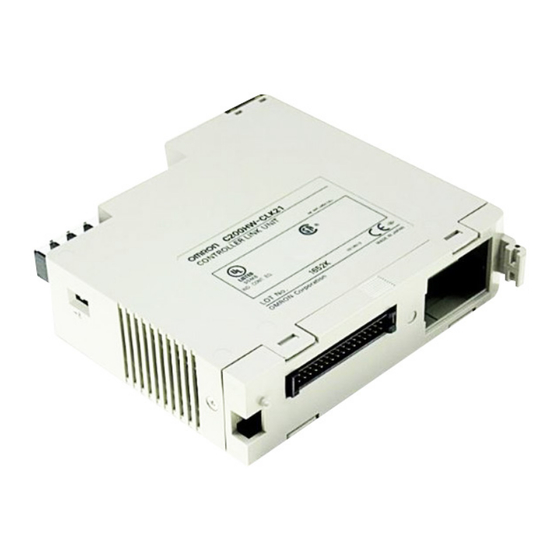
- Page 5 CS-series Controller Link Unit CONTROLLER LINK UNIT Lot No. 040901 0000 OMRON Corporation 1. 1. In the I/O Table Window, right-click on the Controller Link Unit, and then select Unit Manufacturing Information. 2. The following Unit Manufacturing Information Dialog Box will be displayed.
- Page 6 Using the Unit Version Labels Unit version labels are provided with the product. These labels can be attached to the front of previous Controller Link Units to differentiate between Controller Link Units of different unit versions. Unit Version Notation The unit versions are indicated in this manual as follows: Notation in product nameplate Ver.1.2 or later after the lot number CS/CJ-series Controller Link Units Blank after the lot number...
- Page 7 viii...
- Page 8 TABLE OF CONTENTS PRECAUTIONS ........Intended Audience ............General Precautions .
- Page 9 SECTION 5 Data Links ........105 What Are Data Links? .
- Page 10 TABLE OF CONTENTS SECTION 10 Adding Nodes and Editing Active Data Link Tables ..331 10-1 Adding Nodes Using a Repeater Unit......... . 10-2 Changing the Data Link Tables with Active Data Links .
- Page 11 TABLE OF CONTENTS...
-
Page 12: About This Manual
About this Manual: This manual describes the installation, setup, and operation of the C200HW-CLK21, CS1W-CLK21- V1, CJ1W-CLK21-V1, CVM1-CLK21, and CQM1H-CLK21 Controller Link Units for C200HX/HG/HE, CS/CJ-series, CVM1, CQM1H-series, and CV-series PLCs, and includes the sections described below. The Controller Link Units are used to connect these PLCs to a Controller Link Network. Infor- mation is also provided in this manual on CS1W-RPT01/02/03 Repeater Units. - Page 13 Unit and changing data link tables while the data links are active. Appendix A provides a list of standard OMRON products related to Controller Link Networks. Appendix B provides easy reference to the words in PLC memory areas used by Controller Link Net- works.
- Page 14 WHETHER SUCH CLAIM IS BASED ON CONTRACT, WARRANTY, NEGLIGENCE, OR STRICT LIABILITY. In no event shall the responsibility of OMRON for any act exceed the individual price of the product on which liability is asserted. IN NO EVENT SHALL OMRON BE RESPONSIBLE FOR WARRANTY, REPAIR, OR OTHER CLAIMS...
-
Page 15: Application Considerations
Application Considerations OMRON shall not be responsible for conformity with any standards, codes, or regulations that apply to the combination of products in the customer's application or use of the products. At the customer's request, OMRON will provide applicable third party certification documents identifying ratings and limitations of use that apply to the products. -
Page 16: Performance Data
Performance data given in this manual is provided as a guide for the user in determining suitability and does not constitute a warranty. It may represent the result of OMRON's test conditions, and the users must correlate it to actual application requirements. Actual performance is subject to the OMRON Warranty and Limitations of Liability. - Page 17 xviii...
-
Page 18: Table Of Contents
This section provides general precautions for using the Controller Link Unit and related devices. The information contained in this section is important for the safe and reliable application of the Controller Link Unit. You must read this section and understand the information contained before attempting to set up or operate a Controller Link Unit. -
Page 19: Intended Audience
It is extremely important that a PLC and all PLC Units be used for the speci- fied purpose and under the specified conditions, especially in applications that can directly or indirectly affect human life. You must consult with your OMRON representative before applying a PLC System to the above mentioned appli- cations. -
Page 20: Operating Environment Precautions
Operating Environment Precautions !Caution Execute online edit only after confirming that no adverse effects will be !Caution Confirm safety at the destination node before transferring a program to Operating Environment Precautions !Caution Do not operate the control system in the following locations: !Caution Take appropriate and sufficient countermeasures when installing systems in !Caution The operating environment of the PLC System can have a large effect on the •... -
Page 21: Applications Precautions
Applications Precautions Applications Precautions !WARNING !Caution Failure to abide by the following precautions could lead to faulty operation or xxii Observe the following precautions when using the Controller Link Unit. Failure to abide by the following precautions could lead to serious or possibly fatal injury. - Page 22 Applications Precautions • Double-check all wiring and switch settings before turning ON the power supply. Incorrect wiring may result in burning. • Wire all connections correctly. • Mount Units only after checking terminal blocks completely. • Be sure that the Bus Connection Units and other items with locking devices are properly locked into place.
-
Page 23: Conformance To Ec Directives
EMC Directives OMRON devices that comply with EC Directives also conform to the related EMC standards so that they can be more easily built into other devices or the overall machine. The actual products have been checked for conformity to EMC standards (see the following note). -
Page 24: Features And System Configuration
This section provides basic information on Controller Link Networks, and will give the reader an overview of what Controller Link Networks can do and how best to use them. Overview ........... . . 1-1-1 What Is the Controller Link? . -
Page 25: Overview
CJ-series PLC The Controller Link is an FA network that can send and receive large data packets flexibly and easily among the OMRON C200HX/HG/HE Programma- ble Controllers (PLCs), CS-series PLCs, CJ-series PLCs, CVM1 PLCs, CV- series PLCs, CQM1H-series PLCs, and IBM PC/AT or compatible computers. - Page 26 Overview Connecting Repeater Units Using Twisted-pair Cable (Wired Units) T-Branch Wiring Long-distance Wiring Converting Part of the Transmission Line to Optical Fiber Two Repeater Units of the same model must be used when part of the trans- mission line uses optical fiber. Wired Controller Link Unit CS1W-RPT01 Repeater Units...
- Page 27 Overview Note Connecting Repeater Units Using H-PCF Optical Fiber Cable CS1W-CLK12-V1 Controller Link Unit (token ring mode) CS-series PLC Backup power supply (24 V DC) CS-series PLC CS1W-CLK12-V1 Controller Link Unit (token ring mode) Maximum 62-node Configuration Wired Controller Link Unit Twisted-pair cable 31 nodes max.
- Page 28 Overview Token Bus Mode CS1W-CLK12-V1 CS1W-CLK11 Controller Link Unit Controller Link Unit (token bus mode) CS-series PLC CS-series PLC Backup power supply (24 V DC) Connecting Repeater CS-series and CVM1/CV-series PLCs only. Units Using GI Optical Token Ring Mode Fiber Cable CS1W-CLK52-V1 Controller Link Unit (token ring mode)
- Page 29 Overview Data Links Data links allow the constant sharing of data in predetermined data areas between nodes, between PLCs, or between a PLC and an IBM PC/AT or com- patible computer on the network. Data links do not require the use of commu- nications programs on the PLC (CPU Unit) or IBM PC/AT or compatible computer.
- Page 30 The CMND instruction issues a command to read or write data of other nodes, control, or read error logs. With the Controller LInk Unit, OMRON’s command protocol called “FINS commands” is used. trary commands cannot be issued.
-
Page 31: Features
Overview 1-1-2 Features The Controller Link Network has the following features to meet the various requirements of FA sites. Data Links Flexible and efficient data links can be created for large capacities of data as listed below. Item Number of send words per node Number of send and receive words per node... - Page 32 Overview Compatible with Different Node Configurations The following Controller Link Units are available for communications between different models. It must be noted, however, that the wired system and optical system cannot exist in one Controller Link Network. Wired System Flexible Inter-network Connections The Controller Link Network can connect to other networks (Ethernet, SYS- MAC NET, SYSMAC LINK, and another Controller Link network) via CVM1, CV-series, CS-series, or CJ-series PLCs.
- Page 33 Overview The total length of wired networks can be extended. At a baud rate of 2 Mbps, conventional wired networks can be up to 500 m long. By using two Repeater Units, this can be extended to a maximum of 1.5 km.
-
Page 34: Specifications And Configurations
Specifications and Configurations Change manually created data link tables during data link operation. Note This is possible only with manually created data link tables. Any attempt to Specifications and Configurations 1-2-1 System Configuration Wired Systems Method Allocation addresses and sizes are all specified using the Automatic Data Link Creation Parameters (D30000 Area. - Page 35 Specifications and Configurations CS1W-CLK21-V1 CJ1W-CLK21-V1 Controller Link Unit Controller Link Unit CS-series CJ-series PLC Connecting Repeater Units Using Twisted-pair Cable in Wired Systems C200HW-CLK21 CVM1-CLK21 Controller Link Unit Controller Link Unit CVM1, CV-series C200HX/HG/HE Twisted-pair cable T-Branch Wiring Wired Controller Link Unit...
-
Page 36: General Specifications
Specifications and Configurations Converting Part of the Transmission Line to Optical Fiber Two Repeater Units of the same model must be used when part of the trans- mission line uses optical fiber. Maximum Configuration of 62 Nodes Wired Controller Link Unit The following Controller Link Units/Support Boards must be used to construct a network with more than 32 nodes: Note... -
Page 37: Communications Specifications
Specifications and Configurations 1-2-3 Communications Specifications Wired System Items Communications method N:N token bus Code Manchester code Modulation Baseband code Synchronization Flag synchronization (conforms to HDLC frames) Transmission path form Multi-drop bus Baud rate and maximum The maximum transmission distance varies with the baud rate as follows: transmission distance 2 Mbps: 1 Mbps:... - Page 38 Specifications and Configurations Communications Specifications when Using the CS1W-RPT01 Repeater Unit in a Wired Network Note 1. Specifications within a segment are identical to the specifications of a 2. Maximum transmission distance: Total length of cables in the longest path 3.
-
Page 39: Controller Link Unit Models And Plcs
1.2 Units. Install onto a CPU Rack or Expansion Rack (Classified as a CPU Bus Unit.) 110 g 350 mA Section 1-2 C200HW-CLK21 C200HW-COM01/04 Commu- nications Board and C200HW-CE001/002/012 Bus Connection Unit C200HX/HG/HE PLCs (Except C200HE-CPU11(-Z)) 2 maximum CPU Backplane 2 max. - Page 40 Specifications and Configurations Note A Controller Link Support Board can be installed into an IBM PC/AT or com- Item Model CVM1-CLK21 External appearance Installation None required. devices CVM1 and CV-series PLCs Max No. of 4 maximum Units per PLC Unit CPU Backplane 3/5/10 slots Expansion CPU...
- Page 41 Specifications and Configurations CS/CJ-series Controller Link Unit Models Item Model Maximum number of send/receive data link words (data link area for sending/receiving that is created for a single node in a single CPU Unit) Data Link Area Maximum number of Units connected to a single CPU Unit Automatic data link setting Changing data link allocations during active data...
-
Page 42: Devices For Connection
Specifications and Configurations 1-2-5 Devices for Connection To set up a Controller Link Network, the following devices are needed in addi- tion to a Controller Link Unit and a PLC. Communications Cables The following shielded twisted-pair cables are recommended for Wired Con- troller Link Network connections. - Page 43 1. Repeater Units do not use a node address. 2. See Connection Procedure for an explanation of how Repeater Units are 3. The following Power Supply Unit is recommended: OMRON S82K Series Relay Terminal Blocks The following Relay Terminal Block can be used to make maintenance easier by facilitating replacement of the Controller Link Unit after system operation has begun.
-
Page 44: Programming Devices
Specifications and Configurations Note Normally, the communications cable must be disconnected from a Wired Con- 1-2-6 Programming Devices Programming Device for the PLC Note troller Link Unit to replace it. Doing this, however, will interrupt communica- tions on the network, requiring that all node be turned OFF to ensure safety before replacing a Unit. - Page 45 Specifications and Configurations Controller Link Support Software (Version 2.00) Using an Independent Computer Controller Link IBM PC/AT or Support Software compatible Setting data link tables Note 2. For automatic data link creation with 1:N allocations or when changing data link tables while the data link is active (CS1W-CLK21-V1 and CJ1W- CLK21-V1), use the CX-Net in CX-Programmer version 3.2 or higher.
- Page 46 Specifications and Configurations Using a Computer Node A computer that is a node on the Network can also be used to control the Controller Link Network. Software Controller Purchased Link Sup- separately port Soft- Provided ware with Con- troller Link Support Board Note Use Controller Link Support Software version 1.1 for an ISA Controller Link...
- Page 47 Specifications and Configurations Controller Link Support Software Menu Overview Menu items: Data Link Set Network parameters Routing tables Echoback test Broadcast test Monitor Network Display Error log Display Node status Display Board setup Maintenance Connection Info* Edit PC ID System setup Note CX-Programmer Edit table...
-
Page 48: Selection Of Communications Functions
Selection of Communications Functions When Operating on Personal Computer as Peripheral Software IBM PC/AT or compatible Setting data link tables When Operating on Personal Computer Connected as a Node Note 1. For further details about the CX-Programmer, refer to the WS02-CXPC@- 2. -
Page 49: Basic Procedures
Basic Procedures other PLCs in other nodes or from one PLC to IBM PC/AT or compatible com- puters. Basic Procedures Preparations C200HX/HG/HE and CQM1H-series PLCs 1,2,3... 1. Perform mounting and wiring. 2. Set the node address on the front rotary switches. 3. -
Page 50: Application Precautions
Application Precautions Data Link Procedure 1,2,3... 1,2,3... Message Service Procedure Application Precautions Note Routing tables are not required if all of the CVM1 and CV-series CPU Units if Note The manufacturing date can be determined from the four-digit lot number on b) This setting is valid only with the CS1W-CLK21-V1 and CS1W- CLK21-V1. - Page 51 Application Precautions Controller Link Network 1 CVM1 or C200HX/HG/HE PLC CV-series PLC Routing tables are necessary at all the nodes regardless. Lot No.: @ 6 ..Manufactured in May 1996 Indicates the last digit of the manufacturing year.
- Page 52 Application Precautions • The Wired Network 62 Node Enable Bit in the DM Parameter Area soft- ware switches of CS1W-CLK21-V1 and CJ1W-CLK21-V1 Units is read when the Unit is restarted. • When using automatic data link creation with 1:N allocation, all nodes must be CS1W-CLK21-V1 or CJ1W-CLK21-V1 Controller Link Units.
- Page 53 Section 1-5 Application Precautions...
-
Page 54: Basic Procedures
This section describes the basic procedures to use the Controller Link Unit. The settings necessary for using each of the functions are also explained briefly. For more details, refer to the following sections on individual functions. Data Links Procedures ......... . 2-1-1 Manually Setting Data Links . -
Page 55: Data Links Procedures
Data Links Procedures Data Links Procedures 2-1-1 Manually Setting Data Links When the data link mode is set for manual data link table creation, the data link tables can be input using the Controller Link Support Software or CX-Pro- grammer. Use the following procedure. 1,2,3... - Page 56 Data Links Procedures 6. Set the data link mode. 7. Register the data link tables by making the following settings for each Contents Method Enable 62 nodes for a Use Support Software wired network. for the PLC or the Pro- gramming Console.
-
Page 57: Automatically Setting Data Links
Data Links Procedures 8. Start the data links. 9. Stop the data links. 2-1-2 Automatically Setting Data Links Data link tables can be automatically created by setting the data link mode to automatic data link table creation. Use the following procedure. 1,2,3... - Page 58 Data Links Procedures 2. Prepare for communications. 3. Turn ON the power to the PLC. 4. Connect the Programming Device. 5. Create I/O tables. 6. Set the data link mode. Contents Method Use the front rotary a. Set the unit num- switches.
- Page 59 CLK21, CJ1W-CLK21-V1, and CJ1W-CLK21 is fixed at 8-bit, re- gardless of the setting. • Equality layout: Previous automatic creation method (Compatible with CS1W-CLK21-V1, CJ1W-CLK21-V1, CS1W-CLK21, CJ1W-CLK21, C200HW-CLK21, CVM1-CLK21, and CQM1H-CLK21) Contents Method Use the Support a. Set the data link mode Software or Pro- to automatic.
- Page 60 Data Links Procedures • 1:N allocation (Compatible with CS1W-CLK21-V1 and CJ1W-CLK21- Common Type Contents Method Use Support Soft- a. Set the data link mode ware for the PLC to automatic. including Program- ming Console (see note). b. 1:N setting Area c.
- Page 61 Data Links Procedures 1 to 1 Type Contents Method Use Support Soft- a. Set the data link mode ware for the PLC to automatic. including Program- ming Console (see note). b. 1:N creation c. Set the area d. Set the data link start word e.
- Page 62 Data Links Procedures 8. Start the data links. 9. Stop the data links. Chain Type Contents Method Use Support Soft- a. Set the data link mode ware for the PLC to automatic. including Program- ming Console (see note). b. 1:N creation c.
-
Page 63: Message Service Procedure
Message Service Procedure Message Service Procedure The following steps outline the basic procedure for using the message ser- vice. 1,2,3... 1. Install and wire the Units. 2. Prepare for communications. 3. Turn ON the power to the PLC. 4. Create the I/O tables. 5. - Page 64 Message Service Procedure 6. Set the data link mode. Contents Enable 62 nodes for a Use Support Software wired network. for the PLC or a Pro- gramming Console. Note When using fewer than 33 nodes, make sure that the Wired Network 62 Node Enable Bit in the DM Parameter Area software switches is turned OFF to restrict the network to 32 nodes maximum.
- Page 65 Message Service Procedure Section 2-2...
-
Page 66: Installation And Wiring
This section describes how to install a Controller Link Unit and how to wire the Controller Link Network. Component Names and Functions ....... . . 3-1-1 CS-series Controller Link Units . -
Page 67: Component Names And Functions
Component Names and Functions Component Names and Functions 3-1-1 CS-series Controller Link Units CLK21-V1 This section describes the names and functions of the Controller Link Unit components. This section also describes the operation of the indicators. (Refer to p.45 and 276) Indicators LED indicators that display the Unit and network status. - Page 68 Component Names and Functions Wired Unit Indicators For details refer to 9-1 Troubleshooting Using Indicators . Name Color Status Green (operating) Not lit ERC (communica- tions error) Not lit (PLC error) Not lit Yellow (network participa- tion) Not lit Yellow (send) Not lit Yellow...
-
Page 69: Cj-Series Controller Link Units
Component Names and Functions Dimensions (Unit: mm) CLK21-V1 3-1-2 CJ-series Controller Link Units CLK21-V1 ERH M/A LNK RD TER SW BD H BD L SHLD Indicators (Refer to pages 45, 276) LED indicators that display the Unit and network status. UNIT Unit Number Switch (Refer to page 86) One rotary switch. - Page 70 Component Names and Functions Wired Unit Indicators Name Color Status Green (operating) Not lit Yellow (terminating resis- Not lit tance) ERC (communica- tions error) Not lit (PLC error) Not lit Yellow (network participa- tion) Not lit Yellow (send) Not lit Yellow (receive) Not lit...
- Page 71 Component Names and Functions Dimensions (Unit: mm) CLK21-V1 ERH M/A LNK RD UNIT NODE BAUD RATE TER SW BD H BD L SHLD Section 3-1...
-
Page 72: C200Hx/Hg/He Controller Link Unit
Component Names and Functions 3-1-3 C200HX/HG/HE Controller Link Unit CLK21 NODE NO. #0, #1 BAUD RATE SHLD Terminating resistance switch (underneath the Unit) A slide switch. Use this switch to set the terminating resistance to ON for nodes at both ends of the Controller Link Network. Wired Unit Indicators (Refer to p. - Page 73 Component Names and Functions For details refer to 9-1 Troubleshooting Using Indicators . Dimensions (Unit: mm) Name Color Status Yellow (receive) Not lit Note Even when the local node does not participate in the data link, the indicator will be lit if there are manually set data links active on the network.
-
Page 74: Cvm1 And Cv-Series Controller Link Unit
Component Names and Functions 3-1-4 CVM1 and CV-series Controller Link Unit CLK21 UNIT NODE BAUD RATE BAUD RATE BIT2 BIT1 RATE 2MBP 1MBP 500KBP TER SW BD H BD L SHLD Wired Unit Indicators (Refer to p. 51 and 287) Indicators LED indicators that display the Unit and network status. - Page 75 Component Names and Functions For details refer to 9-1 Troubleshooting Using Indicators . Dimensions (Unit: mm) Name Color Status Yellow (send) Not lit Yellow (receive) Not lit Note Even when the local node does not participate in the data link, the indicator will be lit if there are manually set data links active on the network.
-
Page 76: Cqm1H-Series Controller Link Unit
Component Names and Functions 3-1-5 CQM1H-series Controller Link Unit bit/s Wired Unit Indicators (Refer to p. 53 and 276) Indicators LED indicators that display the Unit and network status. Node address switches Two rotary switches. The node address of the Unit on the Controller Link Network is set in 2-digit decimal. -
Page 77: Wire-To-Wire Repeater Unit
Component Names and Functions For details refer to 9-1 Troubleshooting Using Indicators . Dimensions (Unit: mm) bit/s 3-1-6 Wire-to-Wire Repeater Unit SL1 Terminal Block for Communications Cable Terminals to connect to the Controller Link Network communications cable (twisted-pair cable). Baud rate switch Power Terminal Block Terminals to connect to the power supply (24 V DC) that... - Page 78 Component Names and Functions Repeater Unit Indicators Dimensions (Unit: mm) Two, 4.5 dia. Name Color Status Green (Power supply) Not lit T/R1 Yellow (SL1 communicat- ing) Not lit Yellow (SL2 2 communicat- Not lit Section 3-1 Meaning Power supply is ON. Power supply is OFF.
-
Page 79: Wire-To-Optical (H-Pcf) Repeater Unit
Component Names and Functions 3-1-7 Wire-to-Optical (H-PCF) Repeater Unit SL1 Terminal Block for Communications Cable Terminals to connect to the Controller Link Network communications cable (twisted-pair cable). Baud rate switch Power Terminal Block Terminals to connect to the power supply (24 V DC) that drives the Repeater Unit. -
Page 80: Wire-To-Optical (Gi) Repeater Unit
Component Names and Functions Dimensions (Unit: mm) Two, 4.5 dia. 3-1-8 Wire-to-Optical (GI) Repeater Unit SL1 Terminal Block for Communications Cable Terminals to connect to the Controller Link Network communications cable (twisted-pair cable). Baud rate switch Power Terminal Block Terminals to connect to the power supply (24 V DC) that drives the Repeater Unit. -
Page 81: Unit Installation
Unit Installation Repeater Unit Indicators Dimensions (Unit: mm) Two, 4.5 dia. Unit Installation Note 1. Always turn off power to the PLC before mounting the Controller Link Unit Name Color Status Green (Power supply) Not lit T/R1 Yellow (SL1 communicat- ing) Not lit Yellow... -
Page 82: Mounting Controller Link Units
Unit. Conduct wiring and instal- lation with this label in place. If wire scraps get into the Unit, it will malfunc- tion. vent overheating. Overheating will cause the Unit to malfunction. C200HW-CLK21 Controller Link Unit C200HW-CLK21 Controller Link Unit... - Page 83 Note Tighten the screws on the Backplane to a torque of 1.2 N • m. Tighten the fixed screws on the CPU Unit to a torque of 0.9 N • m. Other Communications Unit C200HW-CLK21 Controller Link Unit C200HW-CE002 Bus Connection Unit...
- Page 84 Unit Installation CPU Backplane CV500-BC101, CVM1-BC103/CV500-BC051, CVM1-BC053/CV500-BC031 3/5/10 slots Expansion CPU Rack CV500/BI111 Unit CPU Backplane Of these slots, 11 slots installation is possible in up 2/3/5/8/10 slots to 8 slots (unit Ver. 1.2 or later). Installation in Expansion up to 4 slots Backplane is possible for pre-Ver.
- Page 85 Unit Installation CPU Backplane CS1W-BC103, CS1W-BC083, CS1W-BC053, CS1W-BC033, CS1W-BC023 2/3/5/8/10 slots CS Expansion Backplane CS1W-BI103, CS1W-BI083, CS1W-BI053, CS1W-BI033 3/5/8/10 slots C200H Expansion I/O Backplane Note When installing several CS-series CPU Bus Units at the same time, a total of 16 CS-series CPU Bus Units maximum may be installed. Up to eight CS/CJ-series Controller Link Units with unit version 1.2 or later can be connected to a single CPU Unit.
- Page 86 Unit Installation CJ-series PLCs Up to a total of four Controller Link Units for CJ-series PLCs can be connected in a CPU Rack or a Expansion Rack. (Be sure to secure the Units with the top and bottom sliders.) CPU Rack CJ-series Expansion Rack CJ-series Expansion...
-
Page 87: Mounting A Repeater Unit
Unit Installation Example: Using the C200HW-PA204 Power Supply Unit supplying a maxi- mum current of 4.6 A (5 V) and maximum power of 30 W. Name CPU Backplane (8 slots) CS1W-BC083 CPU Unit CS1H-CPU67H Controller Link Unit (Optical) CS1W-CLK21-V1 0.33 A Total CQM1H-series PLCs Only one Controller Link Unit can be connected in a CQM1H-series PLC. - Page 88 Unit Installation Screw-mounting a Repeater Unit Use M4 81 mm Mounting a Repeater Unit on DIN Track 1,2,3... 1. Unlock the DIN Track mounting pins located on the rear of the Repeater 2. Attach the Repeater Unit by hooking it onto the DIN Track from above (1) 3.
-
Page 89: Wiring
Wiring PFP-100N2 PFP-100N/50N End Plate: PFP-M (2 Plates required per Repeater Unit) Wiring 3-3-1 Communications Cables Using the specified twisted-pair cable, connect all nodes using the multidrop method. Terminating resistance switch (ON) Communications Cables The following shielded twisted-pair cables should be used for Controller Link Network connections. - Page 90 Unit. Conduct wiring and instal- lation with this label in place. If wire scraps get into the Unit, it will malfunc- tion (C200HW-CLK21, CS1W-CLK21-V1, CJ1W-CLK21-V1, and CQM1H- CLK21 only). the Unit to malfunction (C200HW-CLK21, CS1W-CLK21-V1, CJ1W- CLK21-V1, and CQM1H-CLK21 only). CVM1-CLK21 C200HW-CLK21...
- Page 91 Wiring Using a Relay Terminal Block C200HW-CLK21 (End node) BD H BD L SHLD Terminating resistance (ON) Ground Note 1. Mounting and dismounting during communications is not possible for Re- 2. Use the recommended crimp terminals when connecting the cable’s signal...
- Page 92 Wiring 5. Twist firmly the portion of the signal lines that are exposed. 6. Apply vinyl tape or heat-shrinking tube to the end of the cover that was 7. Mount the crimp terminal onto the signal lines and the shield line. Use M3 8.
- Page 93 Wiring Note 1. Always turn OFF the power to the PLC before connecting the communica- 2. Always use a crimp terminal for wiring. If a wire that has only been twisted 3. Use the recommended crimp terminals. 4. When mounting the crimp terminal, always use the appropriate tools for 5.
-
Page 94: Repeater Units
Wiring 3-3-2 Repeater Units Power Supply Wiring 1,2,3... Note 10. When bending a communications cable, allow 60 mm or more for the bend- ing radius (R). 11. Do not place any object on the communications cable. 12. Supply power only after checking the wiring thoroughly. 13. - Page 95 2.5 A max. (24 V DC with rise time 5 ms) The following Power Supply Unit is recommended: OMRON S82K Series Optical fiber cable (H-PCF or GI) can be used to create an optical connection in part of a wired network.
- Page 96 Wiring 5. Move the cable connector so that the loose ends are on the left-hand side, Example: Connections for Duplex Operation of Communications Units Even in token-ring mode, the network will be broken and communications may be disrupted if disconnections occur at two or more places. Be sure not to allow connectors to be disconnected during communications.
- Page 97 Wiring Communications Cables Optical Bus or Optical Ring System (H-PCF Cable) Note The following devices are required for the Optical Bus or Optical Ring (H-PCF) Controller Link Network. The cable and connectors are the same as those used for Optical SYSMAC LINK Networks. Optical Fiber Cables (Indoor Use Only) Use the following Optical Fiber Cables (Hard Plastic-clad Fiber: H-PCF).
- Page 98 Wiring Optical Fiber Cables with Connectors (Indoor Use Only) The following Optical Fiber Cables are available with Connectors already attached. Note 1. Consult a specialist tradesman if cables with outdoor specifications are re- 2. The cables listed above are black and have power supply lines and tension 3.
- Page 99 Wiring CS1W-RPT03 (GI) Wired Controller Link Unit Note 1. Always use the specified Optical Fiber Cables. 2. Although the Optical Fiber Cables can be distinguished by the markings or 3. The maximum distance between nodes depends on the type of GI cable Connection Procedure Use the following procedure to connect Optical Fiber Cables to a Unit.
- Page 100 Wiring Item Minimum Standard Numerical Aper- 0.21 ture (N.A.) Transmission loss Connection loss --- Transmission bandwidth Remove the covers from the tips of the cables’ ST connectors if there are covers protecting the ST connectors. Optical Connector Cover Rotate the cover 90 counterclockwise.
-
Page 101: Constructing Networks With Repeater Units
Constructing Networks with Repeater Units Note L length of the test light source. 62.5/125 m AGF Cable Item Minimum Standard Numerical Aper- 0.28 ture (N.A.) Transmission loss Connection loss --- Transmission bandwidth Note L length of the test light source. Connectors ST Connector Constructing Networks with Repeater Units... -
Page 102: Segments
Constructing Networks with Repeater Units 4. Repeater Units can be connected in a network in advance if new nodes are 3-4-1 Segments Repeater Units divide a wired Controller Link network into segments. Seg- ments are comprised of nodes connected in a multi-drop configuration using wire cables. -
Page 103: Number Of Repeater Units
Constructing Networks with Repeater Units Wire 3-4-2 Number of Repeater Units The number of Repeater Units that can be connected in a Wired Controller Link Network depends on the mode of connection. When Repeater Units are used, a maximum of 32 Units, including Controller Link Units/Support Boards and Repeater Units, can be connected within a single segment. - Page 104 Constructing Networks with Repeater Units Long-distance Wiring: 2-stage Repeater Unit Connection Not more than 2 Repeater Units (2 stages) must be passed for any node to reach any other node Partial Optical Conversion: 2-stage Repeater Unit Connection Two Wire-to-Optical Repeater Units make up a single set counted as a single stage.
-
Page 105: Terminating Resistance
Constructing Networks with Repeater Units The path from one node to another travels via three Repeater Units (3 stages). This kind of network is NOT allowed. Note If the Repeater Units are used incorrectly, communications errors may occur, or nodes may not be able to participate in the network. 3-4-3 Terminating Resistance In a Wired Controller Link Network, turn ON the terminating resistance... - Page 106 Constructing Networks with Repeater Units Partial Conversion to Optical Fiber Segment 1 Terminating Resistance: ON Combining T-Branch Wiring (2-stage Repeater) and Partial Optical Fiber Segment 1 Terminating resistance: ON Terminating resistance: ON Terminating resistance: ON Note When constructing a network using Repeater Units, each segment must sat- isfy all of the following requirements: Terminating Terminating...
- Page 107 Section 3-4 Constructing Networks with Repeater Units...
-
Page 108: Preparations For Communications
This section describes the settings required for starting communications. These basic settings are required for both data links function and the message service. Carry out the settings described here before turning on power to the Controller Link Unit. CS-series Controller Link Units ........4-1-1 Overview. -
Page 109: Cs-Series Controller Link Units
CS-series Controller Link Units CS-series Controller Link Units The following settings are required for a Controller Link Unit used with a CS- series PLC. 4-1-1 Overview CLK21-V1 4-1-2 Unit Number Set the unit number for each Unit using the rotary switches on the front of the Unit. -
Page 110: Node Addresses
CS-series Controller Link Units Set the node address using a small flat-blade screwdriver, being careful not to damage the rotary switches. Note 1. Always turn OFF the PLC’s power before setting the unit number. 2. When setting a Unit for the first time or changing the existing setting, create 3. -
Page 111: Baud Rates
CS-series Controller Link Units 4. When CS1W-CLK21-V1 and CJ1W-CLK21-V1 Units are used with other 5. To construct a network that uses a node address higher than 32, it is nec- 6. Only node addresses 1 through 32 can be used on networks for which 62 7. -
Page 112: Terminating Resistance
CJ-series Controller Link Units 2. The default setting is 2 Mbps, 500 m. 4-1-5 Terminating Resistance Turn ON the terminating resistance using the switch on the bottom of the Unit for the Units of both ends of the Network. The terminating resistance is required at both ends of a Network to absorb unnecessary signals and reduce noise. -
Page 113: Overview
CJ-series Controller Link Units 4-2-1 Overview CLK21-V1 ERH M/A LNK RD UNIT NODE BAUD RATE TER SW BD H BD L SHLD 4-2-2 Unit Number Set the unit number for each Unit using the rotary switches on the front of the Unit. -
Page 114: Node Addresses
CJ-series Controller Link Units 5. The default setting is “0.” 6. The unit number determines the words used by the Controller Link Unit in 4-2-3 Node Addresses Set the node addresses of each Unit on the Network using the rotary switches on the front of the Unit. -
Page 115: Baud Rates
CJ-series Controller Link Units 6. Only node addresses 1 through 32 can be used on networks for which 62 7. The Wired Network 62 Node Enable Bit in the DM Parameter Area soft- 8. The send sequence for the data link areas is determined according to the 9. -
Page 116: C200Hx/Hg/He Controller Link Units
C200HX/HG/HE Controller Link Units Note 1. Always turn OFF the PLC’s power before setting the terminating resistance 2. Turn ON the switch to connect terminating resistance at the nodes at both 3. The TER LED indicator will light when the terminating resistance switch is 4. -
Page 117: Overview
C200HX/HG/HE Controller Link Units 4-3-1 Overview CLK21 NODE NO. #0, #1 BAUD RATE SHLD 4-3-2 Node Addresses Set the node addresses of each Unit on the Network using the rotary switches on the front of the Unit. The node address is used to identify each node in the Network can be set to any number between 01 and 32. -
Page 118: Baud Rates And Operating Levels
C200HX/HG/HE Controller Link Units Set the node address using a small flat-blade screwdriver, being careful not to damage the rotary switches. Note 1. Always turn OFF the PLC’s power before setting the node address. 2. Do not set the same node address twice within the same Network. An error 3. -
Page 119: Terminating Resistance
C200HX/HG/HE Controller Link Units Note 1. Do not use the same operating level for more than one Unit mounted to the 2. Operating levels are used by the CPU Unit to distinguish different Commu- 4-3-4 Terminating Resistance Turn ON the terminating resistance using the switch on the bottom of the Unit for the Units of both ends of the Network. -
Page 120: Cvm1 And Cv-Series Controller Link Units
CVM1 and CV-series Controller Link Units CVM1 and CV-series Controller Link Units The following settings are required for a Controller Link Unit when used with a CVM1 or CV-series PLC. 4-4-1 Overview CLK21 UNIT UNIT NODE NODE BAUD RATE BAUD RATE BAUD RATE BIT2 BIT1 RATE... -
Page 121: Unit Number
CVM1 and CV-series Controller Link Units 4-4-2 Unit Number Set the unit number for each Unit using the rotary switches on the front of the Unit. The unit number is used to identify a CPU Bus Unit within the PLC. Any unit number can be set between 00 and 15. -
Page 122: Baud Rates
CVM1 and CV-series Controller Link Units 2. Do not set the same node address twice within the same Network. An error 3. The send sequence for the data link areas is determined according to the 4. Assign node addresses consecutively beginning from 01 whenever possi- 4-4-4 Baud Rates Set the following pins for the baud rate setting (DIP switch). -
Page 123: Cqm1H-Series Controller Link Units
CQM1H-series Controller Link Units Note 1. Always turn OFF the PLC’s power before setting the terminating resistance 2. Turn ON the switch to connect terminating resistance at the nodes at both 3. The TER indicator will light when the terminating resistance switch is set CQM1H-series Controller Link Units The following settings are required for a Controller Link Unit when used with a CQM1H-series PLC. -
Page 124: Node Addresses
CQM1H-series Controller Link Units 4-5-2 Node Addresses Set the node address of each Unit in the Network using the rotary switch on the front of the Unit. The node address is used to identify each node in the Network. The node address can be set to any value between 01 and 32. Set the node address using a small flat-blade screwdriver, being careful not to damage the rotary switches. -
Page 125: Terminating Resistance
Repeater Units Note Set the same baud rate for all the nodes on the Network. Normal communica- tion cannot be performed unless the same baud rate is set for all the nodes. 4-5-4 Terminating Resistance Turn ON the terminating resistance using the switch on the bottom of the Unit for the Units of both ends of the Network. -
Page 126: Wire-To-Wire Repeater Unit
Repeater Units 4-6-1 Wire-to-Wire Repeater Unit Wire-to-Wire Wire-to-Optical Repeater Unit Repeater Unit CS1W-RPT01 T/R1 T/R2 BD H BD H BD L BD L SHLD SHLD TER SW TER SW BAUD BAUD RATE RATE BD H BD L SHLD DC24V INPUT 4-6-2 Baud Rates Set the same baud rates for all nodes on the network using pins 1 and 2 of... -
Page 127: Terminating Resistance
Repeater Units See pages 15 and 79 for details on the maximum transmission distance. Note 1. Always turn OFF power to the Repeater Unit before setting the baud rate. 2. Set the same baud rate for all nodes on the network. 3. - Page 128 This section describes how to use data links in a Controller Link Network. Refer to SECTION 2 Basic Procedures for an outline of data link application. What Are Data Links?......... . . 5-1-1 Data Link Specifications.
-
Page 129: What Are Data Links
What Are Data Links? What Are Data Links? Data links automatically exchange data in the preset areas between nodes (PLCs and/or computers) on one network. Data links can be freely created for CS/CJ-series PLCs, C200HX/HG/HE PLCs, CVM1, CV-series PLCs, CQM1H-series PLCs, and IBM PC/AT or compatible computers. Two data link areas, area 1 and area 2, can be set for each node. - Page 130 What Are Data Links? Example 3: Manually set data links are used to create flexible data links that meet the needs of the individual system. Manual Setting Options The following options can be set when manually setting data links. Offsets Data of the only the specified number of words can be received starting from the specified word position.
- Page 131 What Are Data Links? Automatically Setting Data Links with Equality Layout Automatic setting can be used to create simple data links. Automatic Setting Data Links with 1:N Allocations This method is used to simplify setting of 1:N allocation data links between master and slave nodes.
- Page 132 What Are Data Links? Note 1. Automatic data link creation with 1:N allocations can only be used with the 2. Controller Link Units and Support Boards other than those listed above 3. The Controller Link Support Board (3G8F7-CLK21-V1) can be used in au- 4.
- Page 133 What Are Data Links? Using Offsets For automatically set data links, all of the send words transmitted by a node are received by other nodes with no change in size. For manually set data links, the size of a receive area can be restricted by specifying a number of words from the beginning word of the words sent by another node.
- Page 134 What Are Data Links? Note The following table shows the status of the data link refresh area when a node 5-1-1 Data Link Specifications Send data of node 1 registered in the data link table generates a communications error. Communications error type A node separates from the network while a data link is running.
-
Page 135: Data Link Specifications
What Are Data Links? 5-1-2 Differences between Manual and Automatic Setting Item Manual setting Determination of Determined by setting data link nodes to be in a tables. data link Data link settings Set in data link tables that are set in the nodes to participate in data links. -
Page 136: Setting Data Links
Setting Data Links Setting Data Links 5-2-1 Selecting Manual or Automatic Setting Specify either the manual or automatic data link mode in the following DM Parameter Area of the PLC’s CPU Unit of the startup node, using a PLC Pro- gramming Device. -
Page 137: Manual Setting
Setting Data Links Note 5-2-2 Manual Setting Transferring from a Programming Device IBM PC/AT or compatible Setting data link tables Note 1. Be sure to set the bit in the DM Area’s (CPU Bus Unit Area’s) software switches (DM30000 + 100 unit number) described as “always set to 0” to 0. - Page 138 Setting Data Links 4. When using the Controller Link Support Software to set a CJ-series Con- Transferring from a Computer Node A data link table is created for each node using the Controller Link Support Software. The data link tables contain all the settings required to create the data links.
- Page 139 Setting Data Links Setting item First data link sta- Set the first word to store data link status. An area of 16 words is tus word used. CIO Area: CIO 001 to CIO 6128 (*1) LR Area: LR 00 to LR 184 (*2) DM Area: DM 0000 to DM 32752 EM Area: Banks 00 to 12, EM 0000 to EM 32752 *1: When IR 000 is specified or when the default setting (...
- Page 140 Setting Data Links C200HX/HG/HE PLCs Note a) The total number of words in data link send and receive areas must not exceed 20,000 per node when using Controller Link Units with unit Ver. 1.2 or later, or 12,000 words per node if using pre-Ver.
- Page 141 Setting Data Links Setting item Area 2 Data link IR Area: IR 000 to IR 235, IR 300 to IR 511 start word LR Area: LR 00 to LR 63 DM Area: DM 0000 to DM 5999 EM Area: Banks 00 to 15, EM 0000 to EM 6143 (EM must be installed) The same area cannot be set for both area 1 and area 2.
- Page 142 Setting Data Links CVM1 and CV-series PLCs Setting item PLC model Set the model of the PLC’s CPU Unit. Nodes 1 to 32 Set the address of the refresh nodes. It cannot be set to a parameter exceeding the “maximum node address”...
- Page 143 Setting Data Links CQM1H-series PLCs Setting item Area 2 Data link CIO Area: CIO 0000 to CIO 2555 start word LR Area: LR 000 to LR 199 (*) DM Area: DM 0000 to DM 8191 (CV500/CVM1-CPU01-EV@) DM 0000 to DM 24575 (Other CPU Units) EM Area: Banks 00 to 07, EM 0000 to EM 32765 (EM must be installed) The same area cannot be set for both area 1 and area 2.
- Page 144 Setting Data Links Setting item First data link sta- Set the first word to store data link status. An area of 16 words is tus word used. IR Area: IR 001 to IR 232 LR Area: LR 00 to LR 48 DM Area: DM 0000 to DM 5984 EM Area: EM 0000 to EM 6128 (EM must be installed) When IR 000 is specified or when the default setting (...
- Page 145 Setting Data Links Precautions (Data link start word – 1) + Total number of send/receive words in area 247 (IR Area) 63 (LR Area) 5999 (DM Area) 6143 (EM Area) c) Refer to the Controller Link Support Boards Operation Manual (W307) for information on the Controller Link Support Board.
-
Page 146: Manual Setting Examples
Setting Data Links 5-2-3 Manual Setting Examples This section shows examples of manually creating data link tables on the Controller Link Support Software. Sample files containing the data link tables are provided on the installation disk for the Software. SAMPLE1.CLK: Same Allocation to All Nodes Data Link Area Structure Device Information Settings Data Link Tables... - Page 147 Setting Data Links Section 5-2 Checking the Data Link Tables Transferring the Data Link Tables Saving the Data Link Tables...
- Page 148 Setting Data Links SAMPLE2.CLK: Different Allocations to Each Node Data links can be created so that one node does not receive from all other nodes or so that some nodes do not send or receive any data at all. In the fol- lowing example, node 2 does not receive data from node 3 and node 3 does not receive data from node 1.
- Page 149 Setting Data Links Data Link Tables SAMPLE3.CLK: Creating Data Link Groups within a Network A data links consisting of multiple groups within a single network can be cre- ated by setting data link tables. Send and receive areas are created for only the nodes in each group, as shown below.
- Page 150 Setting Data Links Section 5-2 Device Information Setting Data Link Tables...
- Page 151 Setting Data Links SAMPLE4.CLK: Receiving Only Part of Send Data and Offsets Only area 2 is used in this example. Note A Controller Link Support Board is used in this example. The Support Board does not have memory areas. The area settings are ignored and byte addresses are used.
-
Page 152: Automatic Setting
Setting Data Links Data Link Tables 5-2-4 Automatic Setting Data links can be automatically created by setting values in the DM Parameter Area of the PLC’s CPU Unit of the startup node. The settings are made using a Programming Console or the CX-Net in the CX-Programmer. The startup node is the node from which the data links are activated. - Page 153 Setting Data Links CS/CJ-series Startup Node Automatic setting for the CS/CJ Series can be performed using either equality layout (previous method), where each node is allocated the same link area size, or 1:N allocations, which allows individually set exchange of data between the master node and slave nodes.
- Page 154 Setting Data Links Automatic Setting, 1:N This method is used to simplify the establishment of 1:N allocation data links Allocations between master and slave nodes. Note 1. Automatic data link creation with 1:N allocations can only be used with the 2.
- Page 155 Setting Data Links Set the following parameter in the DM Parameter Area of the PLC at the star- tup node. DM 30000 + 100 Controller Link Unit number 15 14 13 12 11 10 9 – – – Word N Always specify 0.
- Page 156 Setting Data Links Item Area for area 2 Set the area for area 2 in BCD. DM Area: 82 EM Area: Banks 00 to 07: 90 to 97 Banks 08 to 12: A8 to AC Area 2 not used: 00 Send size per node for Set the number of words in BCD between 0 and 1,000.
- Page 157 Setting Data Links 1:N Allocation, Common Type Features of Common Type 1:N Allocation Address N: D30000 + (100 Word N When bits 6, 5 and 4 are set to 1, 0, and 1 respectively, automatic setting with 1:N allocations is specified. Area 1 (1) Area and start word (2) Size for master...
- Page 158 Setting Data Links 1:N allocation type (Set value 0001 = Common type) N+12 N+13 Area for area 1 N+14 N+15 N+16 N+17 Area for area 2 N+18 N+19 N+20 N+21 N+22 N+23 N+24 N+25 Words N+22 through N+25 register nodes that will participate in the data links.
- Page 159 Setting Data Links Note 1. Node 1 is the master node. Node 1 must be registered as a participating 2. The startup node (the node that sets the above DM Area parameters and Item Send size (number of Set the number of words in BCD between 0 and 1,000. words) for master node The total number of send words for master node of area 1 for area 1...
- Page 160 Setting Data Links 3. When using area 2 only, set the area for area 1 and the number of send 4. When using area 1 only, set the area for area 2 and the number of send 5. The total number of words in data link send and receive areas must not ex- 6.
- Page 161 Setting Data Links 1:N Allocations, 1 to 1 Type Features of 1 to 1 Type 1:N Allocation Address N: D30000 + (100 Word N When bits 6, 5 and 4 are set to 1, 0 and 1 respectively, automatic setting with 1:N allocations is specified.
- Page 162 Setting Data Links 1:N allocation type setting (Set value 0002 = 1 to 1 type) N+12 N+13 Area N+14 Number of common send words for master node (BCD) N+15 Number of individual send words for master node (BCD) N+16 N+17 N+18 N+19 N+20...
- Page 163 Setting Data Links Note 1. Node 1 becomes the master node. Node 1 must be registered as a partic- 2. Only one area can be specified when using the 1 to 1 type of 1:N alloca- 3. The startup node (the node that sets the above DM parameter and starts 4.
- Page 164 Setting Data Links 1:N Allocation, Chain Type (Area start word 1) + (Total number of send and receive words of master node *) 6143 (when using the IR or CIO Area) 199 (when using LR Area) 32767 (when using DM or EM Area) * Total number of send and receive words in master node = Number of common send words in master node + Number of individual send words in master node...
- Page 165 Setting Data Links Word N 1:N allocation type setting (Set value 0003=Delivery type) N+12 N+13 Area N+14 N+15 N+16 N+17 N+18 N+19 N+20 N+21 N+22 N+23 N+24 N+25 Note Setting Range for Automatic Creation with 1:N Allocation, Chain Type • Each slave nodes receives data from the previous node and then sends data to the next node.
- Page 166 Setting Data Links Note 1. Node 1 becomes the master node. Node 1 must be registered as a partic- 2. Only one area can be specified when using the chain type of 1:N alloca- 3. The startup node (the node that sets the above DM parameter and starts 4.
- Page 167 Setting Data Links Example: IR/CIO Area Example: DM Area Total number of words in data link send and receive areas of master node = Number of common send words in master node + Number of individual send words in each node Number of nodes par- ticipating in data links (including both master nodes and slave nodes) 5.
- Page 168 Setting Data Links 11. If the LR Area in the C200HX/HG/HE or CQM1H-series PLC is automati- C200HX/HG/HE Startup Node Set the following DM Parameter Area of the PLC of the startup node. Level 0 = DM 6400 Level 1 = DM 6420 15 14 13 12 11 10 9 –...
- Page 169 Setting Data Links Item Send size (number of Set the number of words in BCD between 0 and 1,000. words) for node of area 1 The total number of send words for area 1 and area 2 must not exceed 1,000. When area 1 is not used, set to 0.
- Page 170 Setting Data Links CVM1 or CV-series Startup Node N: DM 2000 + 100 (Unit number of Controller Link Unit) 15 14 13 12 11 10 9 – – Word N 0: Always 0. – : Other settings Area 1 data link start word (BCD) Area 1 type Number of send words per node of area 1 (BCD) Rightmost 4 digits of data link start word of area 2 (BCD)
- Page 171 Setting Data Links Note 1. When data links are automatically created for networks containing Item Send size (number of Set the number of words in BCD between 0 and 1,000. words) for node of area 2 The total number of send words of area 1 and area 2 must not exceed 1,000.
- Page 172 Setting Data Links Example: IR/CIO Area Example: DM Area 2. If the LR Area in a C200HX/HG/HE or CQM1H-series PLC is manually set C200HX/HG/HE or CQM1H-series PLCs CVM1, CS/CJ, or CV-series PLCs 2555 C200HX/HG/HE or CVM1, CS/CJ, or CV-series PLCs CQM1H-series PLCs DM000 DM000...
- Page 173 Setting Data Links CQM1H-series Startup Node Set the following DM Parameter Area of the PLC of the startup node. 15 14 13 12 11 10 9 – – – DM 6400 0: Always 0. – : Other settings Area 1 data link start word (BCD) DM 6401 Area 1 type DM 6402...
-
Page 174: Automatic Setting Example
Setting Data Links 5-2-5 Automatic Setting Example This section shows an example of DM Parameter Area settings and the data link areas that are created as a result. DM Parameter Area Set the parameters in the startup node as follows: Settings for Equality Layout Item... - Page 175 Setting Data Links Data Link Areas Created DM Parameter Setting When automatic data link creation with common type1:N allocations is used, Example for 1:N the DM Parameter Area of the startup node is set as follows: Allocation, Common Type Word N+1 to N+11 N+12 N+13...
-
Page 176: Starting And Stopping Data Links
Starting and Stopping Data Links Data Link Areas Note 1. Node 1 is the master node. 2. The startup node (the node that sets the above DM parameter and starts Starting and Stopping Data Links Data link must be started after data link areas have been created. Use any of the methods described below for the startup node to start and stop data links. -
Page 177: Using A Programming Device Or The User Program
Starting and Stopping Data Links 5-3-1 Using a Programming Device or the User Program Set the software switch (AR or DM Start Bit) in the PLC to ON using a Pro- gramming Device or from the user program. The data links will start when the Start Bit changes from OFF to ON or is already ON when power is turned on. -
Page 178: Using The Controller Link Support Software And Cx-Programmer
Starting and Stopping Data Links CVM1 and CV-series Start Bit 15 14 13 12 11 10 9 Word N N: DM 2000 + 100 (unit number) CQM1H-series Start Bit 15 14 13 12 11 10 9 AR 07 5-3-2 Using the Controller Link Support Software and CX-Programmer Data links can be started or stopped using commands on the Data Link Menu of the Controller Link Support Software. -
Page 179: Checking Data Link Status
Checking Data Link Status Issuing the FINS Command from CVM1, CV-series, CS/CJ-series, and CQM1H-series PLCs Data links can be stopped by sending the FINS command “STOP.” The node to which the FINS command is issued must be participating in the data link. Checking Data Link Status There are two methods for checking the status of active data links: 5-4-1... - Page 180 Checking Data Link Status When 8-bit Format is Specified (i.e., when using a C200HX/HG/HE, CVM1, CV-series, or CQM1H-series PLC or when using a CS/CJ-series PLC with the data link status storage format specification in the DM Parameter Area set to 8-bit format) (See note 1.) Node 2 Node 1...
- Page 181 Checking Data Link Status 5. The following shows an example of an insufficient (short) receive area. Sufficient Node 1 Send area Data indicated by is received in node 2. 6. The following shows an example of a remaining receive area. No remaining Node 1 Send...
- Page 182 Checking Data Link Status 5. With CS/CJ-series PLCs, the status of the words from first status word + The flags in the data link status operate as follows: The Data Link Participation Flag and the PLC Status Flag can be used to see if the system has started normally.
- Page 183 Checking Data Link Status The data link status storage area is set as follows: Data link PLC and First data link mode operating level status word Automatic CS/CJ-series PLC Specify in DM 30000 + 100 N + 7 C200HX/HG/HE Specify in DM 6407 16 words between Level 0 C200HX/HG/HE Specify in DM 6427...
-
Page 184: Data Link Status Area
Checking Data Link Status Note The data link storage format setting is enabled with the data link startup node setting. Therefore, if multiple nodes are set as startup nodes, ensure that they all have the same settings. If there are different settings, the format setting will depend on the startup node. -
Page 185: Error Detection Program Example
Checking Data Link Status 5-4-5 Error Detection Program Example When the source node's data link is participating, the AND condition of the data link status for each node can be taken using the Data Link Participation Flag and the Communications Error Flag, and the error output. The following example shows an error output program for cases where the local node data link stops. - Page 186 Checking Data Link Status Processing Data Only when Operation Is Normal Using the IL-ILC and JMP-JME Instructions Perform processing only when operation is normal by creating a program based on program blocks that process data for each node with the IL-ILC and JMP-JME programs.
- Page 187 Checking Data Link Status 2. The BSET(071) instruction is used to write 0000 to the corresponding area 3. With Controller Link data links, if there is an error at the source node, the 4. Refresh processing for the data used in Controller Link data links is per- quently cleared to 0000.
-
Page 188: Message Service
This section explains how to use the message service provided by a Controller Link Unit. It also explains the FINS commands and responses supported by Controller Link Units and those supported by C200HX/HG/HE, CS/CJ-series, CVM1 and CV-series PLCs. Introduction ........... 6-1-1 SEND and RECV . -
Page 189: Introduction
Introduction Introduction A message service is a command/response system used for data transmis- sion between nodes on a network, i.e., PLC to PLC, PLC to computer, and computer to PLC). The message service can also be used to control opera- tions, such as mode changes. -
Page 190: Send And Recv
Introduction Message service Source node: Destination SEND: node 1:1 or 1:N (broadcast) There are no responses for broadcasting. RECV: 1:1 Data length 1,980 bytes max. (990 words) 6-1-1 SEND and RECV I/O memory data from other nodes can be read or written by simply using the program in the CPU Unit of a C200HX/HG/HE, CS/CJ-series, CVM1, CV- series, or CQM1H-series PLC to execute SEND and RECV. - Page 191 Introduction 2. With the message service, there is no guarantee that a message to a des- RECV RECV receives “m” words beginning with S (the beginning word for data transmission at the destination node, M) to the words beginning with D (the beginning word for data reception at the source node).
- Page 192 Introduction C200HX/HG/HE PLCs SEND SEND transmits “n” words beginning with S (the beginning source word for data transmission at the source node) to the “n” words beginning with D (the beginning destination word for data reception at destination node N). @SEND(90) S: Source node beginning send word D: Destination node beginning receive word...
- Page 193 Introduction RECV RECV receives “m” words beginning with S (the beginning word for data transmission at the destination node, M) to the words from D (the beginning word for data reception at the source node) onwards. @RECV(98) S: Destination node beginning send word D: Source node beginning receive word C: Source node first control data word 15 14...
- Page 194 Introduction Indirect Designation of Beginning Words sage may be lost in transit due to noise or some other condition. When using the message service, it is advisable to prevent this situation from oc- curring by performing resend processing at the node where instructions are issued.
- Page 195 Introduction Note Specify the area code according to the following table. Destination node: CS/CJ-series PLC Destination node: C200HX/HG/HE or Area Code CIO (IR etc.) (See note 1.) TIM (Timer) (See note 2.) CNT (Counter) (See note 2.) DM (DM Area) EM (Expansion DM) 10 to Banks 0 to 7...
- Page 196 Introduction CVM1 and CV-series PLCs SEND SEND transmits “n” words beginning with S (the beginning word for data transmission at the source node) to “n” words beginning with D (the beginning word for data reception at the destination node, N.) ( )SEND(192) S: Source node beginning send word D: Destination node beginning receive word...
- Page 197 Introduction RECV ( )RECV(193) S: Source node beginning send word D: Destination node beginning receive word C: Source node first control data word "m" number of send words 0001 to 03DE (Hex): 1 to 990 words Destination network address 00 (Hex): Local network 01 to 7F (Hex): 1 to 127 Destination node M 01 to 20 (Hex): 1 to 32 (or 01 to 3E (Hex): 1 to 62)
- Page 198 Introduction CQM1H-series PLCs SEND SEND transmits “n” words beginning with S (the beginning word for data transmission at the source node) to “n” words beginning with D (the beginning word for data reception at the destination node, N.) @SEND(90) S: Source node beginning send word D: Destination node beginning receive word C: Source node first control data word 15 14...
- Page 199 Introduction RECV RECV receives “m” words beginning with S (the beginning word for data transmission at the destination node, M) to the words from D (the beginning word for data reception at the source node) onwards. @RECV(98) S: Destination node beginning send word D: Source node beginning receive word C: Source node first control data word 1514...
- Page 200 Introduction Indirect Designation of Beginning Words using the message service, it is advisable to prevent this situation from oc- curring by performing resend processing at the node where instructions are issued. With the SEND, RECV, and CMND instructions, resend pro- cessing is performed automatically once the number of retries has been set, so be sure to specify a number other than “0”...
- Page 201 Introduction Note Specify the area code according to the following table. Destination node: CS/CJ-series PLC Destination node: C200HX/HG/HE or Area Code CIO (IR, etc.) (See note 1.) TIM (Timer) (See note 2.) CNT (Counter) (See note 2.) DM (DM Area) EM (Expansion DM) 10 to Banks 0 to 7...
-
Page 202: Cmnd (Cvm1, Cv-Series, Cs/Cj-Series, And Cqm1H-Series Plcs Only)
Introduction 6-1-2 CMND (CVM1, CV-series, CS/CJ-series, and CQM1H-series PLCs Only) The CMND instruction can be executed in the user program in a CVM1, CV- series, CS/CJ-series, or CQM1H-series PLC to perform operations such as reading and writing memory data from and to other nodes, reading status information, and changing the operating mode. - Page 203 Introduction sage service, it is advisable to prevent this situation from occurring by per- forming resend processing at the node where instructions are issued. With the SEND, RECV, and CMND instructions, resend processing is performed automatically once the number of retries has been set, so be sure to specify a number other than “0”...
- Page 204 Section 6-1 Introduction “00” as the local network address in the routing tables, and then specify that number. 2. With the message service, there is no guarantee that a message to a des- tination node will reach its destination. It is always possible that the mes- sage may be lost in transit due to noise or some other condition.
- Page 205 Introduction CQM1H-series PLCs CMND sends “n” bytes of command data beginning with S (the beginning word for storing command data at the source node) to node N. In return, “m” bytes of response data are stored at the source node beginning with D (the beginning word for storing response data).
- Page 206 Introduction Example: Commands for CVM1, CV-series and CS/CJ-series PLCs curring by performing resend processing at the node where instructions are issued. With the SEND, RECV, and CMND instructions, resend pro- cessing is performed automatically once the number of retries has been set, so be sure to specify a number other than “0”...
-
Page 207: Send/Receive Data Areas
Introduction For details on commands for CS/CJ-series PLCs, refer to the CS/CJ-series Programmable Controllers Instructions Reference Manual (W340). For details on commands for CVM1 and CV-series PLCs, refer to the FINS Commands Reference Manual (W227). For details on commands for C200HX/HG/HE PLCs, refer to 6-6 Commands and Responses for C200HX/HG/HE and CQM1H-series PLCs. - Page 208 Introduction C200HX/HG/HE PLCs Note 1. Words in the Internal Relay Area 1 (IR 000 to IR 235) and Special Relay 2. For details on extended DM Area and the number of banks, refer to the op- CVM1 and CV-series PLCs Note 1.
-
Page 209: Selecting Communications Instructions
Selecting Communications Instructions Note 1. SR 253 to SR 255 cannot be written at the source node, even if they are 2. For details on extended DM Area, refer to the operation manual for the PLC Selecting Communications Instructions Do you want to easily read from or write to the I/O memory area? Do you want to intermittently read from a memory area? -
Page 210: Message Service Operations
Selecting Communications Instructions 6-2-1 Message Service Operations Instruc- Source node tion C200HX/ CQM1H CS/CJ, HG/HE CVM1, or CV SEND RECV CMND (See note 1.) Note 1. CMND cannot be used with C200HX/HG/HE PLCs. 2. If a computer is receiving commands, a program is required at the comput- Destination node Communica- tions con-... -
Page 211: Message Service Specifications
Selecting Communications Instructions 6-2-2 Message Service Specifications Item Transmission format C200HX/HG/HE PLCs 1:1 SEND or RECV 1:N SEND (broadcast) CS/CJ-series, CVM1,CV-series, or CQM1H-series PLCs 1:1 SEND, RECV, or CMND 1:N SEND or CMND; (broadcast) Packet length SEND: 990 words (1,980 bytes) max. RECV: 990 words (1,980 bytes) max. -
Page 212: Using The Message Service
Using the Message Service Using the Message Service With SEND, RECV, and CMND, the Network Instruction Enabled Flag and Network Instruction Error Flag are generally written into the program as input conditions, as shown below. Only one instruction can be executed at a time for any given communications port. -
Page 213: Network Status
Using the Message Service C200HX/HG/HE PLCs CVM1, and CV-series PLCs Name Network Instruction Enabled Flag Network Instruction Error Flag CQM1H-series PLCs Network Status The nodes on the network are shown in the following illustrations. C200HX/HG/HE PLCs Operating level 0 AR 08 AR 09 CS/CJ-series, CVM1, and CV-series PLCs... - Page 214 Using the Message Service SEND/RECV Flag Operations Example Network Instruction Enabled Flag Communications instruction (SEND/RECV/CMND) Network Instruction Error Flag Communications instruction response code Communications Instruction Response Codes The status after a communications instruction has been executed is reflected in the words shown in the following table. During instruction execution, it becomes “00”...
- Page 215 Using the Message Service C200HX/HG/HE and The results of executing SEND and RECV instructions are reflected as shown CQM1H-series PLC in the following table. Response Codes CS/CJ-series, CVM1, and The results of executing SEND, RECV, and CMND instructions are reflected CV-series Response as one word (two bytes) of data.
- Page 216 Using the Message Service Simultaneous Execution of Communications Instructions C200HX/HG/HE PLCs Controller Link Unit CPU Unit Port Operating level #0 Port Operating level #1 There is only one communications port per operat- ing level, so no more than one communications in- struction can be executed per operating level at one time.
- Page 217 Using the Message Service PLC Programming Examples CS/CJ-series PLCs Execution condition 000000 A20207 120002 (See note 1.) 120001 120000 (See note 1.) 120000 A20207 Network Instruction Error Flag 120000 A21907 (Continued on the next page) The transmission program will run when CIO 000000 KEEP turns ON, provided that the Network Instruction Ena- 120000...
- Page 218 Using the Message Service (Continued from the previous page) Execution condition 000001 A20207 120000 (See note 1.) 120003 120002 (See note 1.) 120002 A20207 Network Instruction Error Flag 120002 A21907 120002 120003 A21907 Note 1. With CS/CJ-series PLCs, the Network Instruction Enabled Flag in A20200 2.
- Page 219 Using the Message Service C200HX/HG/HE PLCs Execution condition 00000 25204 31002 31001 31000 31000 25204 Network Instruction Error Flag 31000 25203 (Continued on the next page) The transmission program will run when IR 00000 KEEP(11) turns ON, provided that the Network Instruction En- 31000 abled Flag is ON and the RECV instruction has not been executed.
- Page 220 Using the Message Service (Continued from the previous page) Execution condition 00001 25204 31000 31003 31002 31002 25204 Network Instruction Error Flag 31002 25203 31002 31003 25203 Note When using the sample program, make sure that the bits and words used in the sample program are not the same as those in the user program or by Spe- cial I/O Units.
- Page 221 Using the Message Service CVM1 and CV-series PLCs I0000 A502 1200 1200 1200 1200 A502 1200 A502 I0000 A502 1200 1200 1200 1200 A502 1200 A502 1200 1200 A502 Note When using the sample program, make sure that the bits and words used in the sample program are not the same as those in the user program or Special I/O Units.
-
Page 222: Fins Commands And Responses
FINS Communications Service The FINS communications service is a communications protocol developed by OMRON for FA control devices. It can be used for reading from and writing to PLC memory, or for controlling various operations, without having to create a user’s program at the PLC. The FINS communications service has its own... -
Page 223: Applicable Units For Fins Commands
FINS Commands and Responses Command Codes The command code consists of two bytes of data, and indicates the contents of the command. A FINS command must begin with a 2-byte command code, and any parameters must follow the command code. Response Codes The response code consists of two bytes of data, and indicates the result of the command execution. -
Page 224: Commands And Responses For Controller Link Units
Commands and Responses for Controller Link Units Commands and Responses for Controller Link Units 6-5-1 Command Codes Command Data link operation mode code Active Inactive Not valid Valid Valid Not valid Valid Valid Valid Valid Valid Valid Valid Valid Valid Valid Valid Valid... -
Page 225: Controller Data Read
20 (Hex) (i.e., spaces) will be returned for the remain- ing bytes. In the version numbers shown below, the spaces are represented by boxes (@). Model Unit for C200HX/HG/HE PLCs: C200HW-CLK21@@@@@@@@ Unit for CVM1/CV-series PLCs: CVM1-CLK21@@@@@@@@@@ Unit for CS-series PLCs: Unit for CJ-series PLCs:... -
Page 226: Controller Status Read
Commands and Responses for Controller Link Units tions Controller version number, and the third represents the Unit version number. Wired/Optical (response) The connection method for the Controller Link Unit (wired or optical ring). The configuration is as follows: Node Address (response): The Controller Link Unit’s node address is returned between 01 and 3E Hex (1 to 62). - Page 227 Commands and Responses for Controller Link Units Status 2 (response): For C200HX/HG/HE, CVM1, and CV-series Controller Link Units, always set to 00 (Hex). For CS/CJ-series and CQM1H-series PLCs, the Unit’s setting status is returning in the following configuration. Status 3 (response): Error information. The configuration is as follows: 1: Error log exists 1: Data link error stop 1: Controller transmitter error...
-
Page 228: Network Status Read
Commands and Responses for Controller Link Units Network participation status (response): The following diagram shows the bits corresponding to node addresses in the Controller Link Network. When a bit is returned as “1,” it means that the corresponding node is participating in the network. - Page 229 Commands and Responses for Controller Link Units ON, the network participation status of nodes 33 to 62 is returned in the upper four bits of bytes 17 through to the lower four bits of byte 32. In other models, the areas corresponding to nodes 33 to 62 are reserved for system use. Actual communications cycle time (response): The actual communica- tions cycle time is returned in units of 100 s in hexadecimal.
-
Page 230: Data Link Status Read
Commands and Responses for Controller Link Units Data link data error counter (response): The total number of data link data reception errors occurring at all nodes is returned as a total count from the time the power was turned on. It is expressed, in hexadecimal, as one byte per node. - Page 231 Commands and Responses for Controller Link Units Status flag (response): The overall data link status is returned in one byte of data, as shown in the following diagram. Data link operational status Data link mode (response): The data link mode during operation is returned in one byte of data, as follows: 01 (Hex): Automatic (Equality Layout) 81 (Hex): Automatic (1:N allocation)
-
Page 232: Echoback Test
Commands and Responses for Controller Link Units 4. Any node which is not active in the network retains the status that existed 5. Only the PLC operation status and PLC error status will be refreshed for 6-5-8 ECHOBACK TEST Executes an echoback communications test between specified nodes. Command Block Response Block Parameters... -
Page 233: 6-5-10 Broadcast Test Data Send
Commands and Responses for Controller Link Units 6-5-10 BROADCAST TEST DATA SEND Broadcasts test data to all nodes in a specified network. Command Block There is no response to this command. The control data must be set as follows when this command is issued: The transmission and reception status is checked by comparing the number of times this command is issued with the number of receptions parameter of the BROADCAST TEST RESULTS READ command. -
Page 234: 6-5-12 Error Log Clear
Commands and Responses for Controller Link Units Note 6-5-12 ERROR LOG CLEAR Command Block Response Block The configuration of each error record is as follows: 1st byte Error code Details Minute Second Error code, details: These parameters show the contents of errors. For details, refer to 9-3-2 Error Codes. -
Page 235: Commands And Responses For C200Hx/Hg/He And Cqm1H-Series Plcs
Commands and Responses for C200HX/HG/HE and CQM1H-series PLCs Commands and Responses for C200HX/HG/HE and CQM1H-series PLCs 6-6-1 Command Codes Command PLC mode code MONITOR Valid Valid Valid Valid Valid Valid Valid Valid Not valid Not valid Valid Valid Valid Valid Valid Valid Valid... - Page 236 Commands and Responses for C200HX/HG/HE and CQM1H-series PLCs Memory area Data DM Area Word contents Expansion DM Word contents Note The meanings of the memory area codes for the Expansion DM area are shown in the following table. Only the current bank (98) or bank 0 (90) can be specified for CQM1H-series PLCs.
-
Page 237: Memory Area Read
Commands and Responses for C200HX/HG/HE and CQM1H-series PLCs Data Configuration 6-6-3 MEMORY AREA READ Command Block Response Block Parameters The configuration of the various types of data that can be read or written is shown below. The number of bytes required for each type of data is also given. -
Page 238: Memory Area Write
Commands and Responses for C200HX/HG/HE and CQM1H-series PLCs Memory Areas The following areas can be read. (Refer to 6-6-2 Memory Area Designations for PLC word/bit address designations): 6-6-4 MEMORY AREA WRITE Writes data to the specified number of consecutive words starting from the specified word. -
Page 239: Multiple Memory Area Read
Commands and Responses for C200HX/HG/HE and CQM1H-series PLCs 6-6-5 MULTIPLE MEMORY AREA READ Reads the contents of the specified number of non-consecutive memory area words, starting from the specified word. Note If there is an error in the command code or an address, no data will be read. Command Block Response Block Parameters... -
Page 240: Program Area Write
Commands and Responses for C200HX/HG/HE and CQM1H-series PLCs Response Block Command Response Program code code Parameters Note If the designated number of bytes is larger than the program area, the pro- 6-6-7 PROGRAM AREA WRITE Command Block Command Program code Response Block Parameters Beginning address... -
Page 241: Run
Commands and Responses for C200HX/HG/HE and CQM1H-series PLCs No. of bytes (command and response): The command specifies the num- ber of bytes of data to write. This must be an even number of 07C6 (Hex) or smaller (1990 or smaller in decimal). The number of bytes actually written will be returned in the response. -
Page 242: 6-6-10 Controller Data Read
Commands and Responses for C200HX/HG/HE and CQM1H-series PLCs Response Block 6-6-10 CONTROLLER DATA READ Reads the following data: Command Block Response Block Command Response Program code code number Parameters Controller model and Controller version (response): Both are returned in ASCII, within 20 bytes (i.e., within 20 ASCII characters). If the model or ver- sion information does not require 20 bytes of data, the remainder of the bytes will be filled with spaces (20 hexadecimal). -
Page 243: 6-6-11 Controller Status Read
Commands and Responses for C200HX/HG/HE and CQM1H-series PLCs 6-6-11 CONTROLLER STATUS READ Reads the status of the Controller. Command Block Response Block Parameters Status (response): The operating status of the PLC as follows: Mode (response): One of the following PLC modes: Fatal error data (response): The contents of fatal error information from the PLC. -
Page 244: 6-6-12 Clock Read
Commands and Responses for C200HX/HG/HE and CQM1H-series PLCs 6-6-12 CLOCK READ Command Block Response Block Parameters 6-6-13 CLOCK WRITE Note Be sure to specify all data. Command Block Response Block FAL/FALS No. (response): The number of the highest priority FAL/FALS error is returned as BCD between 00 and 99 (decimal) to the second byte. -
Page 245: 6-6-14 Error Clear
Commands and Responses for C200HX/HG/HE and CQM1H-series PLCs Parameters 6-6-14 ERROR CLEAR Note The cause of the error must be removed before executing the ERROR CLEAR Command Block Response Block Parameters 6-6-15 FORCED SET/RESET Note This command cannot be used to release the status of Completion Flags for Year, month, date, hour, minute, second, day (command): Each specified value is expressed in BCD. -
Page 246: 6-6-16 Forced Set/Reset Cancel
Commands and Responses for C200HX/HG/HE and CQM1H-series PLCs Command Block Command No. of Set/Reset code bits/flags specification Response Block Parameters No. of bits/flags (command): The number of bits/flags to be processed. Note Multiple bits/flags can be forced set/reset, and the status will be retained until the forced set/reset is cleared. -
Page 247: 6-6-17 Multiple Forced Status Read
Commands and Responses for C200HX/HG/HE and CQM1H-series PLCs Response Block Note The bits (flags) in the following memory areas can be force-set or force-reset. 6-6-17 MULTIPLE FORCED STATUS READ Command Block Response Block Command Response code code Parameters Note Forced status is read by words for the IR, SR, LR, HR, or AR area and by bits/ Command Response code... -
Page 248: Response Codes
Response Codes Response Codes This section describes the response codes returned with responses to FINS commands. Response codes can be used to confirm normal completion of command execution or to troubleshoot problems when commands fail. For fur- ther troubleshooting information, refer to SECTION 9 Troubleshooting and Maintenance of this manual and to the operation manuals for specific Units or Systems. -
Page 249: Network Relay Errors
Response Codes 6-7-2 Network Relay Errors A network relay error will occur whenever a command cannot reach the desti- nation. These errors can occur for several reasons: 1) Data was not success- fully passed between two Link Units, 2) Data was not passed successfully between a Link Unit and another Unit, such as the PLC’s CPU Unit, or 3) The destination of a gateway does not exist. -
Page 250: Response Codes And Troubleshooting
Response Codes Example 1 Example 2 Example 3 6-7-3 Response Codes and Troubleshooting Main code Sub- code 00: Normal completion In this example, data cannot be transferred between Controller Link Units due to some cause such as a routing table error. MRES –... - Page 251 Response Codes Main code Sub- code 01: Local node error 02: Destination node error 03: Communications con- troller error 04: Not executable Probable cause Local node not part of Network Token time-out, node address too large Set the local node’s node address below Number of transmit retries exceeded Maximum number of frames exceeded Either check the execution of events in the Node address setting error (range)
- Page 252 Response Codes Main code Sub- code 05: Routing error 10: Command format error 11: Parameter error Probable cause Destination node address is not set in the routing table. Routing table isn’t registered. Routing table error The maximum number of relay nodes was exceeded in the command.
- Page 253 Response Codes Main code Sub- code 20: Read not possible The data is protected. 21: Write not possible The specified area is read-only or is Probable cause An attempt was made to download a file that is being uploaded. The registered table does not exist or is incorrect.
- Page 254 Response Codes Main code Sub- code 22: Not executable in cur- rent mode 23: No Unit 24: Start/stop not possi- 25: Unit error Probable cause The mode is wrong (executing). Data links are active. The mode is wrong (inactive). Data links are active. The PLC is in the PROGRAM mode.
- Page 255 Response Codes Main code Sub- code 26: Command error 30: Access right error 40: Abort Probable cause The specified area is not protected. This response code will be returned if an attempt is made to clear protection on an area that is not protected. An incorrect password has been speci- fied.
-
Page 256: Network Interconnections
This section describes the method used to connect multiple networks through CS/CJ-series, CVM1, and CV-series PLCs. The section also describes remote programming and monitoring with Programming Devices. What is Network Interconnection? ....... . . 7-1-1 Interconnecting Controller Link Networks. -
Page 257: What Is Network Interconnection
What is Network Interconnection? What is Network Interconnection? Network interconnection enables commands and responses for the message service to be sent and received across multiple networks. The four networks listed below can be interconnected to achieve this. FA Networks OA Network 7-1-1 Interconnecting Controller Link Networks Controller Link Networks can be connected through a CS/CJ-series, CVM1,... - Page 258 What is Network Interconnection? Although 2,012 bytes of data (including the header) can be sent and received with a Controller Link, the maximum amount of data is limited by any network the data passes through, i.e., the network with the smallest capacity will deter- mine the limit.
-
Page 259: Remote Programming And Monitoring
Remote Programming and Monitoring Remote Programming and Monitoring A remote PLC can be programmed and monitored across a network from a Programming Device connected to a PLC. 7-2-1 Local Networks SYSMAC Support Software and CV Support Software A Programming Device connected to a C200HX/HG/HE, CVM1, or CV-series CPU Unit can program and monitor a C200HX/HG/HE, CVM1, or CV-series PLC on the same network. -
Page 260: Remote Controller Link Networks
Remote Programming and Monitoring CX-Programmer A CX-Programmer connected to a CS/CJ-series, C200HX/HG/HE, CVM1, CV-series, or CQM1H CPU Unit can program and monitor a CPU Unit on the same network. Programming and monitoring are possible, including CPU Units that are different to the one to which the Programming Device is con- nected. -
Page 261: Other Remote Networks
Remote Programming and Monitoring CX-Programmer A CX-Programmer connected to a CS/CJ-series, C200HX/HG/HE, CVM1, CV-series, or CQM1H-series CPU Unit can program and monitor any other PLC on another Controller Link Network. Other types of PLC, different to the one to which the CX-Programmer is connected can also be programmed or monitored on remote networks. -
Page 262: Routing Tables
Routing Tables CX-Programmer A CX-Programmer connected to a CS/CJ-series, C200HX/HG/HE, CVM1, CV-series, or CQM1H-series CPU Unit can program and monitor any other PLC on a different type of network (Ethernet, SYSMAC NET, or SYSMAC LINK) through a CS/CJ-series, CVM1, or CV-series PLC. Programming Device CX-Programmer CS/CJ-series, C200HX/HG/... -
Page 263: Setting Routing Tables
Setting Routing Tables 2. The network address is the address of the network connected to the Unit Relay Network Table A relay network table provides the node and network addresses correspond- ing to the initial relay point (first point the data must go to) en route to a target network (end network) not directly connected to the local PLC. -
Page 264: Routing Table Setting Procedure
Setting Routing Tables 7-4-1 Routing Table Setting Procedure 1,2,3... 7-4-2 Editing Local Network Tables 4. When using a CVM1 or CV-series CPU Unit manufactured prior to April 1996, be sure to register routing tables whether or not the PLC is connect- ing multiple networks. -
Page 265: Editing Relay Network Tables
Setting Routing Tables 7-4-3 Editing Relay Network Tables Note 7-4-4 Saving Routing Tables Note When setting routing tables in multiple PLCs, edit and save all routing tables SIOU Unit No.: Unit number of the Communications Unit (operating level for C200HX/HG/HE PLCs;... -
Page 266: Connecting To The Plc
Setting Routing Tables 7-4-5 Connecting to the PLC Connect the Programming Device to a PLC in the network to transfer the rout- ing tables. All PLCs receiving the routing table settings must have power turned ON for the transfer. Note The Programming Device must be disconnected and then reconnected to a PLC on each network. -
Page 267: Example Routing Table Settings
Setting Routing Tables 7-4-8 Example Routing Table Settings Example 1 SYSMAC NET Link System Network address B Controller Link System Network address A acting as bridge Unit number d Unit number c Unit number b Unit number a Example 2 This section shows examples of routing table settings. - Page 268 Setting Routing Tables Example 3 The network structure example in the figure below shows routing tables for all nodes. Node 1 Routing Tables on PLC 1 Routing Tables on PLC 2 Routing Tables on PLC 3 Routing Tables on PLC 4 Unit 5 Node 6 Network 10...
- Page 269 Setting Routing Tables Routing Tables on PLC 5 Routing Tables on PLC 6 Routing Tables on PLC 7 Local Network Table Relay Network Table SIOU Netwk unit# Local Network Table Relay Network Table SIOU Netwk unit# Local Network Table Relay Network Table SIOU Netwk unit#...
-
Page 270: Communications Timing
This section explains details on Controller Link Network communications. Refer to this section for network communications that require accurate communications timing. Communications Mechanism ........8-1-1 Data Transmissions over the Network . -
Page 271: Communications Mechanism
Communications Mechanism Communications Mechanism 8-1-1 Data Transmissions over the Network In a Controller Link Network, token passing is used to control network access. The right to send, called a “token,” circulates around the network. A node that receives the token is allowed to send data. If the node has data to send, it will attach the data to the token and send them together. -
Page 272: Setting The Polling And Polled Nodes
Communications Mechanism Polling Node Each Controller Link Network always has a Unit that controls communications within the network. This Unit is called the “polling node.” Normally, the node that has the smallest node address in the network is the polling node (see note). -
Page 273: Network Parameters
Communications Mechanism If the node is always to be connected as a polled node when the power is turned on, set it as a polled node. If the node can become a polling node when the power is turned on, set it as a polling node. One of the nodes set as a polling node will serve as the actual polling node. -
Page 274: Specifying Network Parameters
Communications Cycle Time 8-1-4 Specifying Network Parameters The network parameters can be specified from the Controller Link Support Software. This section describes only the allowable setting range for each net- work parameter. Refer to the Controller Link Support Software Operation Manual (W308) for setting procedures. -
Page 275: Inactive Data Links
Communications Cycle Time The number of bytes in each message differs according to the instruction being issued. Calculation Example Communications conditions are as follows: In this example, A to E in the equation have the following values. The communications cycle time is thus as follows: 8-2-2 Inactive Data Links The following equations are used to calculate a communications cycle time... -
Page 276: Data Link I/O Response Time
Data Link I/O Response Time The number of bytes in each message differs according to the instruction being issued. Calculation Example Communications conditions are as follows: In this example, B to E in the equation have the following values. The communications cycle time is thus as follows: Data Link I/O Response Time When accurate communications timing is required, you need to understand data exchange timing and the time required for data transmission and recep-... -
Page 277: Data Processing Time
Data Link I/O Response Time CVM1 and CV-series PLCs When a CVM1 or CV-series CPU Unit is operating in asynchronous mode, Under Asynchronous data exchange with the Controller Link Unit is executed as interrupt process- ing during peripheral processing, regardless of the cycle time of PLC instruc- Operation tion execution. -
Page 278: Calculation Example
Data Link I/O Response Time Note 1. Use the above equations only if only one Controller Link Unit is mounted 2. The execution of some items takes precedence over data link area refresh- 8-3-3 Calculation Example The data links of the Controller Link Unit require a slight time delay from the time the data link area of one node is changed until this change is reflected in the data link area at another node. - Page 279 Data Link I/O Response Time CVM1, CV-series, CS/CJ-series PLCs Under Synchronous Operation or C200HX/HG/ HE and CQM1H-series PLCs Maximum I/O Response The maximum data link I/O response time is calculated for four cases. Time Case 1 The following diagram illustrates the data flow that will produce the maximum data link I/O response time when the cycle time of the PLC at nodes #1 and 7 are greater than the communications cycle time.
- Page 280 Data Link I/O Response Time The equation for maximum data link I/O response time is as follows: Note If the total number of data link words is greater than the maximum number of words that can be exchanged per data exchange, the maximum data link I/O response time will be cycle time of PLC at node #7 In case of the CQM1H, however, the cycle time will be incremented by the value obtained from dividing the total number of data link words by the maxi-...
- Page 281 Data Link I/O Response Time Input Input device Input ON delay Program PLC at node #7 There are three points shown in the diagram above where processing is delayed, increasing the data link I/O response time. 1,2,3... 1. The input arrives in the PLC just after I/O refreshing, causing a delay of up 2.
- Page 282 Data Link I/O Response Time mum number of words (1,200 words) per time. For example, if the total number of data link words is 5,000, the result will be as shown below. The PLC cycle time when data link words exceed 12,000 using a CS/CJ- series Controller Link Unit with unit version 1.2 or later is calculated as fol- lows.
- Page 283 Data Link I/O Response Time 3. At node #7, data from the previous data exchange is still being transferred, 4. The data transferred in data link processing arrives at the PLC at node #7 The equation for maximum data link I/O response time is as follows: Note If the total number of data link words is greater than the maximum number of words that can be exchanged per data exchange, the maximum data link I/O response time will be cycle time of PLC at node #7...
- Page 284 Data Link I/O Response Time Case 4 The following diagram illustrates the data flow that will produce the maximum data link I/O response time when the cycle time of the PLC at node #1 < the communications cycle time and the cycle time of the PLC at node #7 < the communications cycle time.
- Page 285 Data Link I/O Response Time The equation for maximum data link I/O response time is as follows: Note If the total number of data link words is greater than the maximum number of words that can be exchanged per data exchange, the maximum data link I/O response time will be cycle time of PLC at node #7 In case of the CQM1H, however, the cycle time will be incremented by the value obtained from dividing the total number of data link words by the maxi-...
- Page 286 Data Link I/O Response Time The equation for minimum data link I/O response time is as follows: Note If the total number of data link words is greater than the maximum number of words that can be exchanged per data exchange, the maximum data link I/O response time will be cycle time of PLC at node #7 In case of the CQM1H, however, the cycle time will be incremented by the value obtained from dividing the total number of data link words by the maxi-...
- Page 287 Data Link I/O Response Time 2. Data exchange occurs just after the PLC at node #1 passes the token that 3. At node #7, data from the previous data exchange is still being transferred, 4. The data transferred in data link processing arrives at the PLC at node #7 5.
-
Page 288: Message Delay Times
Message Delay Times In this case, the data processing time required for data exchange and the data transmission time are not negligible and need to be included in the calcula- tion. Each time can be determined as follows. Data Processing Time (see page 254.) 0.0025 Data Transmission Time Data transmission time varies with the baud rate. - Page 289 Message Delay Times Note Be sure to take into account the time required for data links and program exe- cution, which are not included in the following example. SEND(192)/SEND(90) executed Link Service processing (source node) Max. transmission delay Max. transmission delay = Link Unit servicing interval (source node) + Link service processing (source node) + Transmission processing + Communica- tions cycle time + Transmission delay + Reception processing + Link Unit ser- vicing interval (destination node) + Link service processing (destination node)
- Page 290 Message Delay Times Reception Processing Number of words transferred Note The I/O response time can increase due to noise or restrictions on the number of frames that can be transmitted while data links are operating. Example In this example, the maximum transmission delay is calculated for an instruc- tion sending 256 words of data in a system with 32 nodes.
- Page 291 Message Delay Times RECV (193)/RECV(98) executed Link service processing (source node) Transmission processing (command) Transmission delay (command) Reception processing (command) Max. transmission delay = Link servicing interval (source node) + Link service processing (source node) + Transmission processing (command) + Communi- cations cycle + Transmission delay (command) + Reception processing (com- mand) + Link servicing interval (destination node) + Link service processing (destination node) + Transmission processing (response) + Communications...
- Page 292 Message Delay Times Reception Processing Commands: 1.3 ms Responses: Number of words transferred The I/O response time can increase due to noise or restrictions on the number of frames that can be transmitted while the data link is operating. Example In this example, the maximum transmission delay is calculated for an instruc- tion receiving 256 words of data in a system with 32 nodes.
-
Page 293: C200Hx/Hg/He And Cqm1H-Series Plcs
Message Delay Times 8-4-2 C200HX/HG/HE and CQM1H-series PLCs SEND(90) The following diagram indicates the data flow which will yield the maximum delay time from the time SEND(90) is executed by the user program to the time the Controller Link Unit stores the data in the destination Unit’s memory. SEND(90) executed Max. - Page 294 Message Delay Times Note This communications cycle time is calculated assuming that there is no node RECV(98) Instruction Maximum Delay Time Note Be sure to take into account the time required for data links and program exe- RECV(98) executed Max. transmission delay Transmission processing (command) Transmission delay...
- Page 295 Message Delay Times Note Commands: Transmission delay time is calculated assuming that the number interval (destination node) + Transmission processing (response) + Communi- cations cycle + Transmission delay (response) + Reception processing (response) + Link Unit servicing interval (source node). Link Servicing Interval (Source and Destination Nodes) Link service processing is the same as the PLC’s peripheral servicing and is approximately 1 ms for Controller Link Units.
- Page 296 Message Delay Times Note This communications cycle time is calculated assuming that there is no node that transmits event frames before the SEND command is executed. Link Unit servicing (source node) Transmission processing (command) Communications cycle time 2 (See note.) Transmission delay (command) Reception processing (command) Link Unit servicing (destination node)
- Page 297 Message Delay Times Section 8-4...
-
Page 298: Troubleshooting And Maintenance
This section provides information on troubleshooting errors that occur during Controller Link Unit operation, as well as daily inspection, cleaning, and other maintenance procedures. Troubleshooting Using Indicators........9-1-1 CS/CJ-series Controller Link Units . -
Page 299: Troubleshooting Using Indicators
Troubleshooting Using Indicators Troubleshooting Using Indicators This section describes the errors indicated by the Controller Link Unit indica- tors and possible remedies. 9-1-1 CS/CJ-series Controller Link Units Troubleshooting with RUN, ERC, ERH and INS Indicators The RUN, ERC, ERH, and INS indicators can be used to check whether Con- troller Link Unit startup and Network participation are operating normally. - Page 300 Troubleshooting Using Indicators Indicators Probable cause Not lit Not lit Not lit Not lit Power is not being sup- plied correctly to the PLC. The Controller Link Unit has become loose. The Controller Link Unit is mounted in the wrong posi- tion.
- Page 301 OFF and ON again. When using node address 33 or higher, configure the network so that all nodes are CS1W-CLK21-V1, CJ1W-CLK21-V1, or 3G8F7-CLK21-V1. The CS1W-CLK21, CJ1W- CLK21, C200HW-CLK21, CVM1-CLK21, or CQM1H- CLK21 cannot be used.
- Page 302 Troubleshooting Using Indicators Troubleshooting with LNK and M/A Indicators Data Link Cannot be The following table describes the LNK and M/A indicators at the startup node Started and their use in troubleshooting when a data link cannot be started. Starting a data link depends on the Controller Link Unit operating normally and participating in the Network.
- Page 303 Troubleshooting Using Indicators Node Cannot Participate The following table describes the LNK and M/A indicators when a node can- in Data Link not participate in the data links. Data link participation depends on the Controller Link Unit operating normally and participating in the Network. Refer to Troubleshooting with RUN, ERC, ERH and INS Indicators earlier in this section and check Unit operation before using the following table.
- Page 304 Those nodes are CS1W-CLK21- V1 or CJ1W-CLK- The maximum num- The polling node is a ber of nodes in the C200HW-CLK21, network is set to 32. CQM1H-CLK21, CVM1-CLK21, CS1W-CLK21, or CJ1W-CLK21. The polling node is a CS1W-CLK21-V1 or CJ1W-CLK-V1.
- Page 305 DM Parameters Area is set to the 8-bit for- mat. The polling node is a C200HW-CLK21, CQM1H-CLK21, CVM1-CLK21, CS1W-CLK21, or CJ1W-CLK21. The polling node is a CS1W-CLK21-V1 or CJ1W-CLK-V1.
-
Page 306: C200Hx/Hg/He And Cqm1H-Series Controller Link Units
Troubleshooting Using Indicators Configuring a Network with 32 Nodes or Less 9-1-2 C200HX/HG/HE and CQM1H-series Controller Link Units Troubleshooting with RUN, ERC, ERH and INS Indicators The RUN, ERC, ERH, and INS indicators can be used to check whether Con- troller Link Unit startup and Network participation are operating normally. - Page 307 Troubleshooting Using Indicators Indicators Probable cause Not lit Not lit Not lit Not lit Power is not being sup- plied correctly to the PLC. The Controller Link Unit has become loose. The Bus Connection Unit has become loose. The Controller Link Unit is mounted in the wrong slot.
- Page 308 Troubleshooting Using Indicators Troubleshooting with LNK and M/A Indicators Data Link Cannot be The following table describes the LNK and M/A indicators at the startup node Started and their use in troubleshooting when a data link cannot be started. Starting a data link depends on the Controller Link Unit operating normally and participating in the Network.
- Page 309 Troubleshooting Using Indicators Node Cannot Participate The following table describes the LNK and M/A indicators when a node can- in Data Link not participate in the data links. Data link participation depends on the Controller Link Unit operating normally and participating in the Network. Refer to Troubleshooting with RUN, ERC, ERH and INS Indicators earlier in this section and check Unit operation before using the following table.
-
Page 310: Cvm1 And Cv-Series Controller Link Units
Troubleshooting Using Indicators Data Link Cannot be Stopping the data link depends on the Controller Link Unit operating normally Stopped and participating in the Network. Read the above explanations before attempting to stop operation. Note Stop the data link from the node at which the LNK indicator is lit (indicating active data links). - Page 311 Troubleshooting Using Indicators • Setting hardware switches. Indicators Probable cause Not lit Not lit Lit Unit operating normally; Network participation nor- mal. Not lit Lit Controller Link Unit faulty. Not lit Not lit Not lit Not lit Power is not being sup- plied correctly to the PLC.
- Page 312 Troubleshooting Using Indicators Indicators Probable cause Not lit Terminating resistance is not set correctly. Cables are not connected correctly. The node address is larger than the maximum node address set for the network parameters. No other nodes exist. No nodes have been set as polling nodes.
- Page 313 Troubleshooting Using Indicators Troubleshooting with LNK and M/A Indicators Data Link Cannot be The following table describes the LNK and M/A indicators at the startup node Started and their use in troubleshooting when a data link cannot be started. Starting a data link depends on the Controller Link Unit operating normally and participating in the Network.
-
Page 314: Repeater Units
Troubleshooting Using Indicators Node Cannot Participate The following table describes the LNK and M/A indicators when a node can- in Data Link not participate in the data links. Data link participation depends on the Controller Link Unit operating normally and participating in the Network. Refer to Troubleshooting with RUN, ERC, ERH and INS Indicators earlier in this section and check Unit operation before using the following table. -
Page 315: Status Area And Troubleshooting
Status Area and Troubleshooting Troubleshooting with the PWR Indicator indicator Unit status Possible error status Power is being sup- plied normally Not lit Power supply error Power supply cables Power supply Repeater Unit Troubleshooting with the T/R1 and T/R2 Indicators indicator Unit status Possible error... -
Page 316: Cs/Cj-Series Controller Link Units
Status Area and Troubleshooting 9-2-1 CS/CJ-series Controller Link Units The status of the Unit and Network is indicated in the following manner in the PLC. Status Area Error Information: CIO 1500 + 25 x (Unit No.) Polling Node Address, Startup Node Address: CIO 1500 + 25 x (Unit No.) + 1 Network Participation Status: CIO 1500 + 25 x (Unit No.) + 2, + 3 Local Data Link Participation Status: CIO 1500 + 25 x (Unit No.) + 6 1: Network parameter error (In PLC's EEPROM) - Page 317 Status Area and Troubleshooting Note Data link status is valid only when the local node is participating in the data link. Confirm that the Local Data Link Active Bit is ON before referencing the data link status. The statuses of bits 12 to 14 are reflected only when using a CS1W-CLK21- V1 or CJ1W-CLK21-V1.
- Page 318 Status Area and Troubleshooting 4-Bit Format Specified Node 4 Node 3 Node 2 Node 8 Node 7 Node 6 Node 12 Node 11 Node 10 Node 16 Node 15 Node 14 Node 20 Node 19 Node 18 Node 24 Node 23 Node 22 Node 30 Node 27...
- Page 319 Status Area and Troubleshooting Bit status Probable cause Communications error is 1: The relevant node is not in the Network. A communications error has occurred as a result of noise. A communications error has occurred. Data link participation is 0: The relevant node is not part of data links.
- Page 320 Status Area and Troubleshooting Other Status Bit status Probable cause Error log exists (CIO 1500 Error information on the + 25 n, bit 15) is 1: ON Controller Link Unit (an error log) has been recorded. Communications controller The Controller Link Unit is send error (CIO 1500 + 25 faulty.
- Page 321 Status Area and Troubleshooting Terminating Resistance Status: CIO 1500 + 25 Bit status Probable cause Data link table error The data link table data in (CIO 1500 + 25 n, bit 1) the CS/CJ CPU Bus Unit is 1: ON Area is damaged.
-
Page 322: C200Hx/Hg/He Controller Link Units
Status Area and Troubleshooting 9-2-2 C200HX/HG/HE Controller Link Units The status of the Unit and Network is indicated in the following manner in the PLC. Status Area Duplicate Operating Levels/Refresh Error: AR 00 Routing Table Error/Unit Restart Bits: AR 01 Network Participation Status: AR 08, AR 09, AR 12, AR 13 Operating level 0 AR 08... - Page 323 Status Area and Troubleshooting Polling Node Address, Startup Node Address: SR 238, SR 242 Operating level 0 SR 238 Data Link Status: SR 239 When the data link status stored in the start word for the manual setting data to SR 241, SR 243 to link table or automatic setting data link parameters is not set or is set to 0, the data link status of only node addresses 1 to 6 will be displayed in the following SR 245...
-
Page 324: Bit Status
Status Area and Troubleshooting Data Link Status: First Data Link Status Word + 0 to + 15 Node 2 Node 1 Node 4 Node 3 Node 6 Node 5 Node 8 Node 7 Node 10 Node 9 Node 12 Node 11 Node 14 Node 13 Node 16... - Page 325 Status Area and Troubleshooting Bit status Probable cause Data link participation is 0: The relevant node is not part of data links. There are no active data links in the Network. Offset error is 1: ON The offset is greater than the number of send words at the relevant node.
-
Page 326: Occurs Again, Replace The
Status Area and Troubleshooting Other Status Bit status Probable cause Duplicate Operating Lev- The same operating level is els/Refresh Error: set twice within the same PLC. Operating level 0: AR0011 Operating level 1: AR0010 A refresh error has occurred between the PLC One of the above flags is 1: and the Unit. -
Page 327: Cvm1 And Cv-Series Controller Link Units
Status Area and Troubleshooting 9-2-3 CVM1 and CV-series Controller Link Units The status of the Unit and Network is indicated in the following manner in the PLC. Status Area Error Information: CIO 1500 + 25 Polling Node Address, Startup Node Address: CIO 1500 + 25 Network Participation Status: CIO 1500 + 25 Local Data Link Participation Status: CIO 1500 + 25 Note Data link status is valid only when the local node is participating in the data... - Page 328 Status Area and Troubleshooting Data Link Status: CIO 1500 + 25 Node 2 Node 1 Node 4 Node 3 Node 6 Node 5 Node 8 Node 7 Node 10 Node 9 Node 12 Node 11 Node 14 Node 13 Node 16 Node 15 Node 18 Node 17...
- Page 329 Status Area and Troubleshooting Bit status Probable cause Communications error is 1: The relevant node is not in the Network. A communications error has occurred as a result of noise. A communications error has occurred. Data link participation is 0: The relevant node is not part of data links.
- Page 330 Status Area and Troubleshooting Other Status Bit status Probable cause Error log exists (CIO 1500 Error information on the + 25 n, bit 15) is 1: ON Controller Link Unit (an error log) has been recorded. Communications controller The Controller Link Unit is send error (CIO 1500 + 25 faulty.
-
Page 331: Cqm1H-Series Controller Link Units
Status Area and Troubleshooting 9-2-4 CQM1H-series Controller Link Units Status Area Error Information: IR 190 Bit status Probable cause Data link table error The data link table data in (CIO 1500 + 25 n, bit 1) the EEPROM of the CPU is 1: ON Unit is damaged. - Page 332 Status Area and Troubleshooting Polling Node Address, Startup Node Address: IR 191 Network Participation Status: IR 192 and IR 193 Local Data Link Participation Status: IR 90 Note Data link status is valid only when the local node is participating in the data link.
- Page 333 Status Area and Troubleshooting Bit Status and Error Processing Data Link Status Bit status Probable cause PLC’s CPU Unit error is 1: A fatal PLC error, non-fatal PLC error, or a watchdog timer error has occurred. The Unit is mounted to a non-compatible PLC.
- Page 334 Status Area and Troubleshooting Other Status Bit status Probable cause Receive area insufficient The send area at the rele- (short) is 1: ON vant node is larger than the receive area and some data cannot be received. Receive area remaining is The send area at the rele- 1: ON vant node is smaller than...
- Page 335 Status Area and Troubleshooting Terminating Resistance Status: IR 95 Bit status Probable cause Routing table error The routing table data (IR 19002) is 1: ON within the CPU Unit’s EEPROM is damaged. There is an error in the routing table setting. Data link table error The data link table data in (IR 19001) is 1: ON...
-
Page 336: Error Log
Error Log Error Log The error log records errors that occur in the Controller Link Unit and the time they occur. The error log can be read or cleared by using Programming Devices, such as the Controller Link Support Software, the CX-Net, or Sup- port Software for the CPU Unit (SYSMAC Support Software), or by using the message service (FINS commands for the Controller Link Unit.) 9-3-1... -
Page 337: Error Codes
Error Log Time Information The time is recorded in BCD with one byte each for the year (the rightmost two digits), month, day, hour, seconds, and minutes of the time the error occurred. Note 1. The PLC’s time information can be read and used in the Controller Link 2. - Page 338 Error Log Error Contents code 000E I/O Bus error 000F PLC initialization error 0010 PLC Setup exceeds capacity 0011 PLC initialization error (Time out) 0012 CPU Unit memory error 0013 CPU Unit write-protected Detail code Correction 1st byte 2nd byte 00 Hex 00 Hex Check the operating...
- Page 339 Error Log Error Contents code 0101 Transmission failed; local node not in Network 0103 Transmission failed; retry count exceeded 0104 Transmission failed; maximum number of frames exceeded. 0105 Transmission failed; node address incorrect 0106 Transmission failed; redundant node address 0107 Transmission failed;...
- Page 340 Error Log Error Contents code 0109 Transmission failed; destination busy 010A Transmission failed; communica- tions controller error 010B Transmission failed; PLC error 010C Transmission failed; unit number incorrect 010D Transmission failed; destination address incorrect 010E Transmission failed; routing tables not registered 010F Transmission failed;...
- Page 341 Error Log Error Contents code 0117 Internal buffer full 0118 Illegal packet discarded 0203 EEPROM error 0206 Number of participating nodes decreased (local node still partic- ipating) 0207 Number of participating nodes decreased (local node not partic- ipating) 0208 Polling node changed 0209 Inconsistent network parameter 020C...
- Page 342 Error Log Error Contents code 0216 Backup power supply error (Opti- cal Units only) 021A Set table logic error 021B Hardware error 021C Data link error inactive 0220 Reduced number of participating nodes (separated nodes) 0221 0222 0223 0230 Data link stop requested 0300 Packet discarded 0601...
-
Page 343: Reading And Clearing Error Logs
Troubleshooting Error Messages in CX-Net Data Link Table Check Error Status The status of each bit indicates that an error has occurred as given in the dia- gram below. 9-3-3 Reading and Clearing Error Logs Error logs can be read or cleared using the Controller Link Support Software, the CX-Programmer, PLC Programming Devices, or the message service. - Page 344 Troubleshooting Error Messages in CX-Net Data Link Table Check Example Display of Error List Note Error message Node XX Link area Total link area 1 Start Address ** exceeded size ** is outside max area size Total link area 2 Start Address ** size ** is outside max area size Node XX Dest Warning: Size outside bounds of...
- Page 345 Troubleshooting Error Messages in CX-Net Data Link Table Check Error message Node XX Dest Over- Warning: Overflow occurred flow Warning: Block outside bounds of Link from node **. Enter value in range ** to ** Node XX Node size Warning: The total node send and receive size of ** exceeds 12000 Total Node send size of **...
-
Page 346: Cleaning And Inspection
Cleaning and Inspection Cleaning and Inspection This section describes cleaning and inspection procedures that are to be per- formed as daily maintenance. 9-5-1 Cleaning Conduct the following periodic cleaning to keep the Controller Link Unit in optimum condition. !Caution Do not use volatile solvents such as benzine or paint thinner, or chemical cloths for cleaning. -
Page 347: Handling Precautions
Remove any lint or threads left from the cloth, and remount the Unit. • When returning a faulty Unit for repairs, always attach a detailed fault report to the Unit and return to you nearest OMRON outlet as listed at the back of this manual. -
Page 348: Setting The Unit After Replacement
Handling Precautions 3. When replacing the Unit, do not reconnect that node to the Network before 9-6-2 Setting the Unit after Replacement After replacing a Controller Link Unit, reset the hardware switches, software switches, and data link tables, and wire it in the same manner as the previous Unit. - Page 349 Handling Precautions CVM1 and CV-series Controller Link Units DM 2000 + 100 n = Unit number CQM1H-series Controller Link Units DM 6400 2. Turn the power off once, connect the Controller Link Network and turn the 3. Return the Polled node/polling node setting of the node in which the Unit CS/CJ-series Controller Link Units DM 30000 + 100 n = Unit number...
-
Page 350: Replacing The Unit
Handling Precautions Using the above procedure to reset the network parameters of the node that was replaced to the same as the other nodes in the Network. !Caution When a C200HX/HG/HE or CQM1H-series Controller Link Unit has been replaced or a CPU Unit has been replaced for a CS/CJ-series, CVM1, or CV- series Controller Link Unit, do not connect that node to the Network before carrying out the above procedures. - Page 351 Handling Precautions 2. Detach the communications cables and the Bus Connection Unit attached 3. Mount the new Controller Link Unit in the PLC and connect the communi- 4. Set the node address, baud rate, operating level (front DIP switch, 5. Turn ON only those PLC for which Units were replaced. 6.
- Page 352 Handling Precautions previous status. If, however, the CPU Unit is replaced, the data link tables and routing tables will need to be reset. 1,2,3... 1. Turn off all nodes in the Controller Link Network. 2. Detach the communications cables attached to the Controller Link Unit to 3.
- Page 353 Section 9-6 Handling Precautions...
-
Page 354: Adding Nodes And Editing Active Data Link Tables
Adding Nodes and Editing Active Data Link Tables This section describes the methods used to perform functions without turning OFF the PLC power to the existing network, such as adding nodes to the Controller Link Network and changing data link tables while the data links are active. 10-1 Adding Nodes Using a Repeater Unit. -
Page 355: 10-1 Adding Nodes Using A Repeater Unit
Adding Nodes Using a Repeater Unit 10-1 Adding Nodes Using a Repeater Unit 10-1-1 Overview The CS1W-RPT01 Repeater Unit can be used to add new nodes to the net- work without turning OFF the power to the existing network. Example of Adding Nodes Using a T-branch Line System Configuration at Startup CS1W-RPT01 Repeater Unit... -
Page 356: 10-1-2 Procedure For Adding Nodes
Adding Nodes Using a Repeater Unit 10-1-2 Procedure for Adding Nodes Check the operating conditions and setting status of the existing network. Set the baud rate and Setting the terminating resistance switch on the Repeater Unit Repeater Unit. Prepare the nodes to be added. - Page 357 Adding Nodes Using a Repeater Unit Check that the new data transmission that will be performed due to the new nodes has been considered in the user program for the existing network before adding the nodes. If the ladder program is not suitable, the system may not operate properly.
- Page 358 Adding Nodes Using a Repeater Unit Before connecting the new nodes to the existing network, always set the poll- ing/polled node setting to Polled. If the nodes are connected to the existing network with this setting set to Polling, the corresponding node may become the polling node for the network, which will affect the network in the following ways.
-
Page 359: 10-2 Changing The Data Link Tables With Active Data Links
Changing the Data Link Tables with Active Data Links 10-2 Changing the Data Link Tables with Active Data Links 10-2-1 Overview The data link tables can be changed and data link tables can be allocated for newly added nodes while the system’s data links are active if the following Controller Link Units and Support Boards are used. -
Page 360: (Theoretical)
Changing the Data Link Tables with Active Data Links Data link area of node with the data link table to be changed Most recent data read from Data link send data Unit Most recent data received Data link receive data from other node Data link communications will continue, so the Communications Error Flag for the data link status will not turn ON in any of the nodes in the network. -
Page 361: Procedure For Changing The Data Link Tables With Cx-Programmer
Changing the Data Link Tables with Active Data Links 10-2-5 Procedure for Changing the Data Link Tables with CX- Programmer The procedure for changing a data link table with active data links is shown here using CX-Programmer version 3.2 and the following system configura- tion. - Page 362 Changing the Data Link Tables with Active Data Links 6. Use the mouse to select node 1, whose data link table is to be changed. 7. Select Online 8. The following message box will be displayed. Click the Yes Button. 9.
- Page 363 Changing the Data Link Tables with Active Data Links 10. The Data Link Table Transfer Confirmation Message Box will be displayed. 11. When the data link table is written correctly, the following message box will Note Transfer data link tables with active data links for one node at a time. When the Online - Transfer to PLC while datalink active field is selected, the follow- ing message box will be displayed.
- Page 364 Section 10-2 Changing the Data Link Tables with Active Data Links...
- Page 365 Section 10-2 Changing the Data Link Tables with Active Data Links...
-
Page 366: A Standard Models
Controller Link Units CS-series PLCs CJ-series PLCs CVM1 and CV-series PLCs CVM1-CLK21 C200HX/HG/HE PLC CQM1H-series PLCs Controller Link Support Board IBM PC/AT or compatible Controller Link Support Software IBM PC/AT or compatible Repeater Units Communications Cables (Twisted-pair Cables) Relay Terminal Block Appendix A Standard Models Applicable PLC... -
Page 367: Standard Models
Standard Models CX-Programmer with CX-Net IBM PC/AT or compatible run- ning Windows 95/ 98 or Windows CPU Units and Programming Devices CPU Units Applicable Name computer CX-Programmer with CX-Net Model number CS-series PLCs CS1H-CPU67-V1 CS1H-CPU66-V1 CS1H-CPU65-V1 CS1H-CPU64-V1 CS1H-CPU63-V1 CS1G-CPU45-V1 CS1G-CPU44-V1 CS1G-CPU43-V1 CS1G-CPU42-V1 CJ-series PLCs... - Page 368 Standard Models Other Products Used with Controller Link Units Refer to the operation manual for the relevant PLC for further information on the above products. Name Model number Bus Connection C200HW-CE001 Unit C200HW-CE002 C200HW-CE012 Communications C200HW-COM01 Boards C200HW-COM04 Appendix A Remarks Required to connect a Controller Link Unit to a C200HZ, C200HX, C200HG, or...
-
Page 370: B Memory Areas
This appendix provides easy reference to the words in PLC memory areas used by Controller Link Networks. CS/CJ-series PLCs Auxiliary Area Word(s) Bit(s) A202 00 to 07 Communications Port Enabled (Network Communi- cations Enabled) Flags A203 to A210 00 to 15 Port #0 to #7 Completion Codes A219 00 to 07... - Page 371 Memory Areas CS/CJ CPU Bus Unit Duplication Error Flag wo CS/CJ CPU Bus Units have been assigned the same unit number. The dupli- Bit A40113 is turned ON when t cated unit number is indicated in A410. CS/CJ CPU Bus Unit Error, Unit Number Flags When an error occurs in a data exchange between the CPU Unit and an CS/CJ CPU Bus Unit, the CS/CJ CPU Bus Unit Error Flag (A40207) is turned ON and the bit in A417 corresponding to the unit number of the Unit where the error occurred is turned ON.
- Page 372 Memory Areas Network Participation Status: CIO 1500 + 25 Local Data Link Participation Status: CIO 1500 + 25 Data Link Status: CIO 1500 + 25 When the first data link status word for manually set data link tables or for automatically set data links is not set or is set to 0, the data link status is stored in the words shown below.
- Page 373 Memory Areas 4-Bit Format Specified Node 4 Node 3 Node 2 Node 8 Node 7 Node 6 Node 12 Node 11 Node 10 Node 16 Node 15 Node 14 Node 20 Node 19 Node 18 Node 24 Node 23 Node 22 Node 30 Node 27 Node 26...
- Page 374 Memory Areas DM Area: CS/CJ CPU Bus Unit Area The CS/CJ CPU Bus Unit Area (DM Area) is allocated to CS/CJ CPU Bus Units according to the unit numbers assigned to them, as shown below. Each Unit is allocated 100 words, of which 10 words are used. In the Con- troller Link Unit this area is called the DM Area.
- Page 375 Memory Areas Parameters for Automatically Setting Data Links with Equality Layout: D30000 + 100 No.) + 1 to 9 (See page 145.) Area 1 data link start word (BCD) Area 1 type Number of send words per node of area 1 (BCD) Rightmost 4 digits of data link start word of area 2 (DM area) (BCD) Area 2 type Number of send words per node of area 2 (BCD)
- Page 376 Memory Areas 1 to 1 Type N+12 N+13 Area N+14 N+15 N+16 N+17 N+18 N+19 N+20 N+21 N+22 N+23 N+24 N+25 Words N+22 through N+25 register nodes that will participate in the data links. The numbers shown in the table are the node addresses.
- Page 377 Memory Areas Words N+22 through N+25 register nodes that will participate in the data links. The numbers shown in the table are the node addresses. The bit status for each node address indicates whether the node is to participate in the data links.
- Page 378 Memory Areas Operating Level Status: SR 252 (See pages 189, 300.) Operating level 1 Operating level 0 AR Area Duplicate Operating Levels/Refresh Error: AR 00 (See page 299.) Routing Table Error/Unit Restart Bits: AR 01 (See page 299.) Data Link Start Bits (See page 154.) 15 14 13 12 11 10 9 AR 07 Network Participation Status: AR 08, AR 09, AR 12, AR 13 (See pages 190, 299.)
- Page 379 Memory Areas Communications Controller Hardware Error, EEPROM Error: AR 11, AR 15 (See page 299.) Operating level 0 AR 11 Service Time: AR 16, AR 17 (See page 299.) Operating level 0 Operating level 1 AR 16 AR 17 Operating Level Connection Status, Inconsistent Network Parameters: AR 24 (See page 299.) DM Parameter Area Software Switches: DM 6400 and DM 6420 (See pages 145, 243, 249, 318.) 15 14 13 12 11 10 9...
- Page 380 Memory Areas Routing Tables (DM 6450 to DM 6499) (See page 243.) When the use of routing tables is enabled by the software switch setting, the routing tables are stored in these words. Do not use them for anything else. CVM1 and CV-series PLCs Auxiliary Area Word(s)
- Page 381 Memory Areas CPU Bus Unit Numbers Bits A41000 through A41015 correspond to CPU Bus Units #0 through #15, respectively. When two CPU Bus Units have the same unit number, the bits corresponding to the unit numbers of the CPU Bus Units involved are turned ON.
- Page 382 Memory Areas Local Data Link Participation Status: CIO 1500 + 25 Data Link Status: CIO 1500 + 25 When the first data link status word for manually set data link tables or for automatically set data links is not set or is set to 0, the data link status is stored in the words shown below.
-
Page 383: Cpu Unit
Memory Areas DM Area: CPU Bus Unit Area The CPU Bus Unit Area (DM Area) is allocated to CPU Bus Units according to the unit numbers assigned to them, as shown below. Each Unit is allocated 100 words, of which 10 words are used. In the Controller Link Unit this area is called the DM Area. - Page 384 Memory Areas Parameters for Automatically Setting Data Links: DM 2000 + 100 page 147.) Area 1 data link start word (BCD) Area 1 type Number of send words per node of area 1 (BCD) Rightmost 4 digits of data link start word of area 2 (BCD) Area 2 type Number of send words per node of area 2 (BCD) First data link status word (BCD)
-
Page 385: Terminating Resistance Status: 0: Off
Memory Areas Communications Unit Flags, Control Bits, and Status Information Local Data Link Participation Status: IR 90 (See page 309.) Data Link Status: IR 91 to IR 93 (See pages 156, 309.) When the first data link status word is not set or is set to the default (0000) for either the manually set data link tables or automatically set data link tables, the data link status is stored in the following words for nodes 1 to 6 only. - Page 386 Memory Areas Controller Link Status Information Error Information: IR 190 (See page 309.) Polling Node Address, Startup Node Address: IR 191 (See page 309.) Network Participation Status: IR 192 and IR 193 (See page 309.) PLC Setup Settings in DM Area Control Bits: DM 6400 (See pages 113, 243, 249, 325.) 1: Network parameter error (In Controller Link's EEPROM) 1: Data link table error (in Controller Link's EEPROM)
- Page 387 Memory Areas Automatic Data Link Parameters: DM 6401 to DM 6409 (See page 150.) DM 6401 Area 1 data link start word (BCD) DM 6402 Area 1 type DM 6403 Number of send words per node of area 1 (BCD) DM 6404 Rightmost 4 digits of data link start word of area 2 (BCD) DM 6405...
-
Page 388: C Using The Relay Terminal Block
Using the Relay Terminal Block This appendix describes how to use the CJ1W-TB101 Wired Controller Link Unit Relay Terminal Block. Using a Relay Terminal Block enables replacing a Controller Link Unit while network communications are still in progress. Appearance Wired Controller Link Unit Relay Terminal Block Relay Terminal Blocks (CJ1W-TB101) can be used on any node but the end nodes to enable replacing the Controller Link Unit with the communications cable connected and turn OFF the power to only the Unit being... - Page 389 Using the Relay Terminal Block Relay Terminal Block Connect the Relay Terminal Block. 4. Attach the terminal block cover to the communications terminal block on the Controller Link Unit. Relay Terminal Block Replacing a Controller Link Unit with a Relay Terminal Block Use the following procedure to replace a Controller Link Unit with a Relay Terminal Block.
- Page 390 Using the Relay Terminal Block Note 1. Signal will still be flowing through the communications cables during the replacement procedure if the network is still operating. Use an insulated screwdriver and be very sure that the metal portions of the Relay Terminal Block or the communications cable crimp terminals do not come into contact with any conductive material.
-
Page 392: Index
Numerics 1 to 1 type 1:N allocations 1 to 1 type chain type common type 4-bit format 8-bit format applications precautions xxii AR Area reading writing asynchronous operation automatic setting 1:N allocations setting example bits controlling Bus Connection Units models C200HX/HG/HE PLCs installation memory areas... - Page 393 settings CJ Series settings CJ-series PLCs CQM1H Series settings CQM1H-series PLCs CS Series settings CS-series PLCs CVM1 and CV Series settings CVM1 and CV-series PLCs models counters changing PV reading Completion Flag status reading PV CPU Units models CQM1H-series PLCs CMND installation instructions...
- Page 394 PLC model number models network interconnecting Controller Link networks interconnecting other OMRON networks other remote networks parameters specifying relay errors remote Controller Link networks node addresses setting C200HX/HG/HE Units CJ-series Wired Units...
- Page 395 reading reading controller status receiving routing table settings status polling cycle definition polling node setting precautions applications xxii general handling operating environment replacing the Unit safety procedures message service programming PLC programming examples remote Programming Devices models programs reading writing RAS functions RECV RECV delay time...
- Page 396 changing PV reading Completion Flag status reading PV troubleshooting status area status flags using indicators unit numbers setting CJ-series Wired Units CS-series Wired Units CVM1 and CV Units Wired Network 62 Node Enable Bit wiring Wired Controller Link Units Index...
- Page 397 Index...
-
Page 398: Revision History
A manual revision code appears as a suffix to the catalog number on the front cover of the manual. The following table outlines the changes made to the manual during each revision. Page numbers refer to the previous version. Revision code Date February 1997 August 1997... - Page 399 Revision code Date February 2003 June 2003 September 2004 January 2006 Revision History Revised content “PC” changed to “PLC” throughout the manual. Information related to the CQM1H-CLK21 was added and information related to the CS1W-CLK21 was removed. In addition, the following changes were made. Page v: Changes made to information on product references.
- Page 400 The Netherlands Tel: (31)2356-81-300/Fax: (31)2356-81-388 OMRON ELECTRONICS LLC 1 East Commerce Drive, Schaumburg, IL 60173 U.S.A. Tel: (1)847-843-7900/Fax: (1)847-843-8568 OMRON ASIA PACIFIC PTE. LTD. 83 Clemenceau Avenue, #11-01, UE Square, Singapore 239920 Tel: (65)6835-3011/Fax: (65)6835-2711 OMRON (CHINA) CO., LTD. Room 2211, Bank of China Tower,...
- Page 401 Authorized Distributor: Cat. No. W309-E1-09 Note: Specifications subject to change without notice Printed in Japan This manual is printed on 100% recycled paper.