Table of Contents
Advertisement
Quick Links
AIR CONDITIONER (MULTI TYPE)
SERVICE MANUAL
Indoor unit
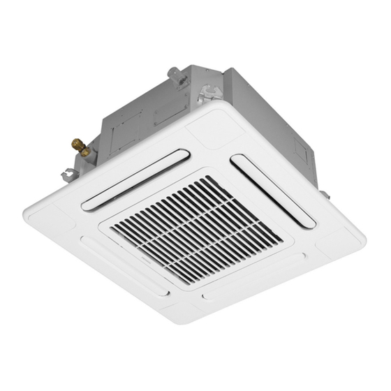
<Compact 4-way Cassette type>
MMU-UP0071MH-UL
MMU-UP0091MH-UL
MMU-UP0121MH-UL
MMU-UP0151MH-UL
MMU-UP0181MH-UL
Ceiling panel: RBC-UM21PG-UL
<Floor Console Exposed type>
MML-UP0071H-UL
MML-UP0091H-UL
MML-UP0121H-UL
MML-UP0151H-UL
MML-UP0181H-UL
MML-UP0241H-UL
<Slim Duct type>
MMD-UP0071SPH-UL
MMD-UP0091SPH-UL
MMD-UP0121SPH-UL
MMD-UP0151SPH-UL
MMD-UP0181SPH-UL
<Floor Console Recessed type>
MML-UP0071BH-UL
MML-UP0091BH-UL
MML-UP0121BH-UL
MML-UP0151BH-UL
MML-UP0181BH-UL
MML-UP0241BH-UL
PRINTED IN JAPAN, Jan., 2023
FILE NO. A10-2209
ToMo
Advertisement
Table of Contents
Troubleshooting

Related Manuals for Toshiba MMU-UP0071MH-UL


Summary of Contents for Toshiba MMU-UP0071MH-UL
- Page 1 FILE NO. A10-2209 AIR CONDITIONER (MULTI TYPE) SERVICE MANUAL Indoor unit <Compact 4-way Cassette type> <Slim Duct type> MMU-UP0071MH-UL MMD-UP0071SPH-UL MMU-UP0091MH-UL MMD-UP0091SPH-UL MMU-UP0121MH-UL MMD-UP0121SPH-UL MMU-UP0151MH-UL MMD-UP0151SPH-UL MMU-UP0181MH-UL MMD-UP0181SPH-UL Ceiling panel: RBC-UM21PG-UL <Floor Console Exposed type> <Floor Console Recessed type> MML-UP0071H-UL...
-
Page 2: Table Of Contents
CONTENTS SAFETY CAUTION ....................... 7 1. SPECIFICATIONS..................... 9 1-1. Compact 4-way Cassette type .................... 9 1-2. Slim Duct type ........................9 1-3. Floor Console Exposed type .................... 10 1-4. Floor Console Recessed type ..................11 2. CONSTRUCTION VIEWS (EXTERNAL VIEWS) ............ 12 2-1. - Page 3 9-7. Maintenance list ....................... 121 9-8. Notice code ........................122 10. P.C. BOARD EXCHANGE PROCEDURES ............123 10-1. Replacement of indoor P.C. boards ................123 11. DETACHMENTS ....................128 11-1. Compact 4-way Cassette ....................128 11-2. Slim Duct ......................... 137 11-3.
- Page 4 SAFETY CAUTION The important contents concerned to the safety are described on the product itself and on this Service Manual. Please read this Service Manual after understanding the described items thoroughly in the following contents (Indications/Illustrated marks), and keep them. The manufacturer shall not assume any liability for the damage caused by not observing the description of this manual.
- Page 5 WARNING Before troubleshooting or repair work, check the ground wire is connected to the ground terminals of the main unit, otherwise an electric shock is caused when a leak occurs. If the ground wire is not correctly connected, contact an electric engineer for rework. Check ground wires.
- Page 6 WARNING After the work has finished, be sure to use an insulation tester set (500V Megger) to check the resistance is 2MΩ or more between the charge section and the non-charge metal section (Ground position). If the resistance value is low, a disaster such as a leak or electric shock is caused at user’s Insulator check side.
-
Page 7: Safety Caution
• Refrigerant (R410A) This air conditioner adopts a HFC type refrigerant (R410A) which does not deplete the ozone layer. 1. Safety Caution Concerned to Refrigerant (R410A) The pressure of R410A is high 1.6 times of that of the former refrigerant (R22). Accompanied with change of refrigerant, the refrigerating oil has been also changed. - Page 8 4. Tools 1. Required Tools for R410A Mixing of different types of oil may cause a trouble such as generation of sludge, clogging of capillary, etc. Accordingly, the tools to be used are classified into the following three types. 1) Tools exclusive for R410A (Those which cannot be used for conventional refrigerant (R22)) 2) Tools exclusive for R410A, but can be also used for conventional refrigerant (R22) 3) Tools commonly used for R410A and for conventional refrigerant (R22) The table below shows the tools exclusive for R410A and their interchangeability.
-
Page 9: Specifications
1. SPECIFICATIONS 1-1. Compact 4-way Cassette type Model name MMU-UP0071MH-UL MMU-UP0091MH-UL MMU-UP0121MH-UL MMU-UP0151MH-UL MMU-UP0181MH-UL Cooling Capacity kBtu/h 15.4 18.0 Heating Capacity kBtu/h 10.5 13.5 17.0 20.0 Electrical Power supply 230V (208V/230V) 1 phase 60Hz characteristics Running current 0.23 0.24 0.25 0.28... -
Page 10: Floor Console Exposed Type
1-3. Floor Console Exposed type Model name MML- UP0071H-UL UP0091H-UL UP0121H-UL UP0151H-UL Cooling capacity kBtu/h 12.0 15.4 Heating Capacity kBtu/h 10.5 13.5 17.0 Electrical Power supply 230V (208V/230V) 1phase 60Hz characteristics Power consumption 208V 0.049 0.049 0.080 0.080 230V 0.058 0.058 0.093 0.093... -
Page 11: Floor Console Recessed Type
1-4. Floor Console Recessed type Model name MML- UP0071BH-UL UP0091BH-UL UP0121BH-UL UP0151BH-UL Cooling capacity kBtu/h 12.0 15.4 Heating Capacity kBtu/h 10.5 13.5 17.0 Electrical Power supply 230V (208V/230V) 1phase 60Hz characteristics Power consumption 208V 0.047 0.047 0.047 0.095 230V 0.056 0.056 0.056 0.114... -
Page 12: Construction Views (External Views)
2. CONSTRUCTION VIEWS (EXTERNAL VIEWS) 2-1. Compact 4-way Cassette type MMU-UP0071MH-UL, UP0091MH-UL, UP0121MH-UL – 12 –... - Page 13 MMU-UP0151MH-UL, UP0181MH-UL – 13 –...
-
Page 14: Slim Duct Type
2-2. Slim Duct type MMD-UP0071SPH-UL, UP0091SPH-UL, UP0121SPH-UL – 14 –... - Page 15 MMD-UP0151SPH-UL, UP0181SPH-UL – 15 –...
-
Page 16: Floor Console Exposed Type
2-3. Floor Console Exposed type MML-UP0071H-UL, UP0091H-UL, UP0121H-UL – 16 –... - Page 17 MML-UP0151H-UL, UP0181H-UL – 17 –...
- Page 18 MML-UP0241H-UL – 18 –...
-
Page 19: Floor Console Recessed Type
2-4. Floor Console Recessed type MML-UP0071BH-UL, UP0091BH-UL, UP0121BH-UL – 19 –... - Page 20 MML-UP0151BH-UL, UP0181BH-UL – 20 –...
- Page 21 MML-UP0241BH-UL – 21 –...
-
Page 22: Wiring Diagrams
3. WIRING DIAGRAMS 3-1. Compact 4-way Cassette type MMU- UP0071MH-UL, UP0091MH-UL, UP0121MH-UL, UP0151MH-UL, UP0181MH-UL – 22 –... -
Page 23: Slim Duct Type
3-2. Slim Duct type MMD- UP0071SPH-UL, UP0091SPH-UL, UP0121SPH-UL, UP0151SPH-UL, UP0181SPH-UL – 23 –... -
Page 24: Floor Console Exposed Type
3-3. Floor Console Exposed type MML- UP0071H-UL, UP0091H-UL, UP0121H-UL, UP0151H-UL, UP0181H-UL, UP0241H-UL – 24 –... -
Page 25: Floor Console Recessed Type
3-4. Floor Console Recessed type MML- UP0071BH-UL, UP0091BH-UL, UP0121BH-UL, UP0151BH-UL, UP0181BH-UL, UP0241BH-UL – 25 –... -
Page 26: Parts Rating
4. PARTS RATING Indoor unit Compact 4-way Cassette type Model MMU-UP***1MH-UL Fan motor ICF-340D60-1 (N) (A) Drain pump motor PMD-08D12TF-2 Float switch FS-0218-102 Pulse motor valve PAM-B25YGTF-2 PAM-B40YGTF-1 P.C. board MCC-1643 TA sensor Lead wire length: 32.2" (818mm) Vinyl tube TC1 sensor Dia.4 size lead wire length: 15.7"... -
Page 27: Refrigerant Cycle Diagram
5. REFRIGERANT CYCLE DIAGRAM Indoor unit Liquid side Gas side Cooling Heating Strainer Capillary tube Heat exchanger at indoor side Pulse Motor Valve (PMV) Strainer Sensor (TCJ) Sensor (TC2) Sensor (TC1) Sensor Fan motor (TA) Explanation of functional parts in indoor unit Functional part name Functional outline Pulse Motor Valve... -
Page 28: Control Outline
6. CONTROL OUTLINE Control Specifications Item Outline of specifications Remarks When power 1) Distinction of outdoor unit supply is reset When the power supply is reset, the outdoors are distinguished and the control is selected according to the distinguished result. 2) Setting of indoor fan speed and existence of air direction adjustment Based on EEPROM data, select setting of the indoor fan... - Page 29 Item Outline of specifications Remarks Room temp. 2) By setting the Set data [06], the setup temperature in Return air temperature control heating operation can be compensated. shift of heating operation (Continued) Set data +0°F +3.6°F +7.2°F +10.8°F Except while sensor of Setup temp.
- Page 30 Item Outline of specifications Remarks Fan speed 1) By the command from remote control, fan speed is HH > H+ > H > L+ > L > UL selection changed. ((HH), (H+), (H), (L+), (L) or [AUTO]) 2) When the fan speed mode [AUTO] is selected, the fan Depends on fan speed mode speed varies by the difference between TA and Ts.
- Page 31 Item Outline of specifications Remarks Fan speed selection Setting of height ceiling mode at Set data [5D] or (Continued): at SW501 on P.C. board. Compact 4-way (only UP015, UP018) (Fan speed selection of UP012 or less are only Standard.) Factory default Type 1 Type 3 Set data...
- Page 32 Item Outline of specifications Remarks Prevention of cold 1. In heating operation, the lowest temperature between TCJ: Temperature of indoor TC1 sensor and the highest temperature between air discharge heat exchanger sensor TC2 and TCJ sensor is set as the upper bound of the •...
- Page 33 Item Outline of specifications Remarks Refrigerant (Oil) Indoor units during stop/thermostat OFF or FAN Control is performed per two recovery control in operation perform following controls when a refrigerant hours or when the outdoor unit cooling operation (compressor oil) recovery signal is received from determines its need.(It varies outdoor unit at the cooling operation, depending on the indoor units...
- Page 34 Item Outline of specifications Remarks Alarm output The alarm output from the indoor P.C. board is output in each Connector CN61 setup indoor unit during group control, but it can be set so as to be (Refer to 8-3-1,8-3-2. output in the header unit and follower units. Optional connector Following the table below, register the setting data in Set data [79].
- Page 35 Item Outline of specifications Remarks Subject model : Louver control 1) Louver position setup Compact 4-way • When the louver position is changed, the position moves necessarily to downward discharge position once to return to the set position. • The louver position can be set up in the following operation range.
- Page 36 Item Outline of specifications Remarks Louver control <<Individual air direction setup>> Subject model : (Continued) Compact 4-way Push the menu button and select 1. Individual louver in the remote control menu, you can set the wind direction for each outlet of indoor units that have 4-way air discharge.
- Page 37 Item Outline of specifications Remarks Louver control <<Selection of Swing mode>> Subject model : Compact 4-way (Continued) Push the menu button, select 2. louver setting in the remote controller menu, then select 1. Swing type, you can select from 3 types of swing operation: “Standard”, “Dual”, or “Cycle”. you can select from 3 types of swing operation: “Standard”, “Dual”, or “Cycle”.
- Page 38 Item Outline of specifications Remarks Louver control • If there is the locked louver in the unit, [ ] goes on the For the setting operation, refer to [How to set louver remote controller screen. (Continued) lock] of Owner's Manual. •...
- Page 39 Item Outline of specifications Remarks Occupancy 1) During the Occupancy sensor operation when there is no The Occupancy sensor sensor people in the Occupancy sensor range, it is automatically can be set up by wired switched to the operation for the absence. remote controller RBC-AWSU5∗...
- Page 40 Item Outline of specifications Remarks Secondary Secondary heating can be used while heating operations are performed. heating <Control Outline (Normal Mode)> 1) If the difference between the indoor temperature and the outdoor temperature is large while the air conditioner is operating, turn ON the secondary heating.
- Page 41 Item Outline of specifications Remarks Secondary DN [C5] Data Secondary heating mode heating 0000 Normal mode (Factory default) (Continued) 0001 Flip mode DN [C6] Data : Set temp. out (high) [ºF(ºC)] -0015 "-0015": 5°F(-15°C) to "0015": 59°F(15°C) "0000": 32°F(0°C) (Factory default) 0015 DN [C7] Data...
-
Page 42: Communication Type, Model Names And The Maximum Number Of Connectable Units
7. COMMUNICATION TYPE, MODEL NAMES AND THE MAXIMUM NUMBER OF CONNECTABLE UNITS 7-1. This air conditioning (U series) has new communication specifications, and TU2C- LINK (U series) and TCC-LINK (other than U series) differ in a communication type. For the communication type and the model names such as each unit or remote controllers, refer to the following table. -
Page 43: Applied Control And Functions (Including Circuit Configuration)
8. APPLIED CONTROL AND FUNCTIONS (INCLUDING CIRCUIT CONFIGURATION) 8-1. Indoor controller block diagram (MCC-1643) 8-1-1. In case of connection of wired remote controller Wired remote controller (Up to 2 units) Schedule timer Display LCD Function setup Display driver Key switch Display LED Function setup DC5V... -
Page 44: In Case Of Connection Of Wireless Remote Controller (Slim Duct Type)
8-1-2. In case of connection of wireless remote controller (Slim Duct type) Wireless remote Indoor unit (Follower) (Follower) #1 (Header) controller receiver Receiving Indoor control P.C. board P.C. board (MCC-1643) DC20V Remote controller Remote controller communication circuit communication circuit Emergent Power operation circuit... -
Page 45: In Case Of Connection Of Wireless Remote Controller (Compact 4-Way Cassette Type)
8-1-2. In case of connection of wireless remote controller (Compact 4-way Cassette type) Indoor unit #1 (Header) (Follower) (Follower) Indoor control P .C. board (MCC-1643) DC20V Remote controller communication circuit EEPROM DC5V TA sensor DC12V Same Same TC1 sensor as left as left TC2 sensor Driver... -
Page 46: Connection Of Both Wired Remote Controller And Wireless Remote Controller
8-1-3. Connection of both wired remote controller and wireless remote controller Wired header remote controller Schedule timer Function setup Display Display LCD driver Key switch EEPROM Function setup DC5V DC5V Power Display LED Key switch circuit Remote controller Power Secondary communication circuit circuit battery... -
Page 47: Indoor Controller Block Diagram (Mcc-1744)
8-2. Indoor controller block diagram (MCC-1744) 8-2-1. In case of connection of wired remote controller Wired header remote controller (Up to 2 units) Schedule timer (weekly timer mode) Display LCD Function setup Display driver Key switch Function setup DC5V DC5V Power Display LED Key switch... -
Page 48: In Case Of Connection Of Wireless Remote Controller
8-2-2. In case of connection of wireless remote controller Indoor unit #1 (Header) (Follower) (Follower) Indoor control P .C. board Wireless remote (MCC-1744) controller receiver DC20V Receiving Remote controller communication circuit P .C. board Remote controller DC5V EEPROM communication circuit Emergent TA sensor Power... -
Page 49: Connection Of Both Wired Remote Controller And Wireless Remote Controller
8-2-3. Connection of both wired remote controller and wireless remote controller Wired header remote controller (Up to 2 units) Schedule timer (weekly timer mode) Function setup Display Display LCD driver Key switch Function setup DC5V DC5V Power Display LED Key switch circuit Remote controller Power... -
Page 50: Indoor Print Circuit Board
8-3. Indoor Print Circuit Board 8-3-1. MCC-1643 • Compact 4-way Cassette type • Slim Duct – 50 –... - Page 51 – 51 –...
-
Page 52: Mcc-1744
8-3-2. MCC-1744 • Floor Console Exposed type • Floor Console Recessed type – 52 –... - Page 53 – 53 –...
-
Page 54: Test Run Of Indoor Unit
8-4. Test run of indoor unit Cooling/Heating test run check The test run for cooling/heating can be performed from either indoor remote controller or outdoor interface P.C. board. Refer to the Installation Manual and Service Manual of outdoor unit for the procedure of the test run from an outdoor interface P.C. - Page 55 <RBC-AMTU3∗ ∗ ∗ ∗ ∗ > TEMP. ON / OFF TIMER SET MODE TIME SAVE VENT FILTER RESET TEST SWING/FIX UNIT LOUVER Procedure Operation contents Push [TEST] button for 4 seconds or more. TEST [TEST] is displayed at the display part and the mode enters in TEST mode.
- Page 56 In case of wireless remote controller Turn on the power of the air conditioner. When power is turned on for the first time after installation, it takes approx. 5 minutes until the remote controller becomes available. In the case of subsequent power-on, it takes approx. 1 minute until the remote controller becomes available.
- Page 57 Check function for operation of indoor unit (Functions at indoor unit side) This function is provided to check the operation of the indoor unit individually without connecting to the remote controller or the outdoor unit. This function can be used regardless of the ON/OFF operation. However, it is recommend to avoid using this function for along time, otherwise the trouble of the equipment may occurred.
-
Page 58: Method To Set Indoor Unit Function Dn Code
8-5. Method to set indoor unit function DN code (When performing this task, be sure to use a wired remote controller.) Procedure Be sure to stop the air conditioner before making settings <RBC-AWSU5∗ ∗ ∗ ∗ ∗ > Push [ Menu] to open the “Menu”... - Page 59 <RBC-AMTU3∗ ∗ ∗ ∗ ∗ > Push the buttons simultaneously and hold for at least 4 seconds. CODE No. The unit No. displayed first is the address of the header indoor unit in group SET DATA SETTING TEST 00 01 UNIT No.
- Page 60 Indoor unit function Code No. (DN Code) table (includes functions needed to perform applied control on site) Description Item At shipment Filter display delay timer 0000: None 0001: 150H Depending on model 0002: 2500H 0003: 5000H type 0004: 10000H t l i f 0001: High degree of dirt (Half of standard time) Central control address 0001: No.1 unit...
- Page 61 Description Item At shipment ° : F ° 0001: °F c i t Depending on model type High-ceiling adjustment (Air flow selection) Timer setting 0000: Available 0001: Unavailable 0000: Available (wired remote controller) (can be performed) (cannot be performed) Dual set point 0000: Unavailable 0002: Available 0000: Unavailable...
- Page 62 Item Description At shipment Notice code 0000: None 0000: None number 01 0001 ~ 0255 : Notice code 0129 : Notice code (201) Notice code 0000: None 0130 : Notice code (202) number 02 (0001 ~ 0255 : TU2C-LINK only) Notice code 0000: None number 03...
- Page 63 [5d] External static pressure & High-ceiling adjustment <Slim Duct type> External static pressure Set data UP007 to 012 UP015,018 0000 0.05 in.WG 0.07 in.WG Standard (Factory default) 0001 0.09 in.WG 0.11 in.WG High static pressure 1 0003 0.13 in.WG 0.15 in.WG High static pressure 2 0004 0.17 in.WG...
-
Page 64: Applied Control Of Indoor Unit
8-6. Applied control of indoor unit Control system using Remote location ON/OFF control box (TCB-IFCB-4UL) Wiring and setting • In the case of group control, the control system functions as long as it is connected to one of the indoor units (control P.C. - Page 65 Ventilating fan control from remote controller [Function] • The start / stop operation can be operated from the wired remote controller when air to air heat exchanger or ventilating fan is installed in the system. • The fan can be operated even if the indoor unit is not operating. •...
- Page 66 ∗ ∗ ∗ ∗ ∗ <RBC-AMTU3 > Push concurrently buttons for 4 seconds or more. The unit No. displayed firstly indicates the header indoor unit address in the group control. In this time, the fan of the selected indoor unit turns on. UNIT LOUVER Every pushing button (left side of the button), the indoor unit numbers in group control are displayed...
- Page 67 Auto-off feature control [Function] • This function controls the indoor units individually. It is used when the start operation from outside is unnecessary but the stop operation is necessary. • A card switch box or card lock helps protect customers from forgetting to turn off the indoor unit. (not including the following Card Input 3) •...
- Page 68 [Control items] External contact terminal Function Close (Status that card is inserted) Open (Status that card is taken out) Manual prohibition release Manual prohibition Card Input 1 (Manual operation) (Operation stop) Manual prohibition release Manual prohibition Card Input 2 (Automatic operation) (Operation stop) Operation status continues Operation status continues and setting temperature...
- Page 69 [The example of Card Input 5 setting] Code No. (DN) setting External contact terminal Case. [16A] [16b] [16C] [16d] [16F] [170] [171] [172] [173] Close (Status that card is inserted) Open (Status that card is taken n out) data data data data data...
- Page 70 Notice code signal Notice code is a function dedicated to TU2C-LINK communication. See service manual for u series outdoor unit for details of Notice code. [Function] • Notice Code is issued if there is signal input to connector of outdoor unit P.C. board. This can be used in cases such as when confirming state of outdoor unit (filter clogging, etc.) by air conditioner system.
- Page 71 Manual address setting using the remote controller Procedure when setting indoor units’ addresses first under the condition that indoor wiring has been completed and outdoor wiring has not been started (manual setting using the remote controller) Wiring example of 2 refrigerant lines Refrigerant line 1 Refrigerant line 2 Outdoor...
- Page 72 <Line (system) address> Push [ ] to black highlight the code (DN), and then push [ ] and [ ] to set the code number to 12. Push [ ] to black highlight the data, and then push [ ] and [ ] to set a system address.
- Page 73 ∗ ∗ ∗ ∗ ∗ <RBC-AMTU3 > SET DATA Code No. TEMP. ON / OFF 2, 5, 8 3, 6, 9 TIMER SET MODE TIME SAVE VENT 4, 7, 10 FILTER RESET TEST SWING/FIX UNIT LOUVER Pair the indoor unit to set and the remote controller one-to-one. Turn on the power.
- Page 74 NOTE <In the case of combining with outdoor units of U series (SMMS-u etc.)> • Turn ON DIP switch 1 of SW100 on the header outdoor unit interface P.C. board the lowest system address number. • After finishing all the settings above, set the address of the central control devices. (For the setting of the central control address, refer to the installation manual of the central control devices.) <In the case of combining with outdoor units other than U series>...
- Page 75 Confirming the indoor unit addresses and the position of an indoor unit using the remote controller Confirming the numbers and positions of indoor units To know the indoor unit addresses though position of the indoor unit is recognized When the unit is individual (the indoor unit is paired with a wired remote controller one-to-one), or it is a group-controlled one.
- Page 76 ∗ ∗ ∗ ∗ ∗ <RBC-AMTU3 > TEMP. ON / OFF Starts TIMER SET MODE running TIME SAVE VENT FILTER RESET TEST SWING/FIX UNIT LOUVER (Execute it while the units are running.) Push the ON / OFF button if the units stop. UNIT LOUVER Push the button (left side of the button).
- Page 77 To check all the indoor unit addresses using an arbitrary wired remote controller. (When communication wirings of 2 or more refrigerant lines are interconnected for central control) ∗ ∗ ∗ ∗ ∗ <RBC-AMTU3 > TEMP. ON / OFF TIMER SET MODE TIME SAVE...
- Page 78 Changing the indoor unit address using a remote controller To change an indoor unit address using a wired remote controller. The method to change the address of an individual indoor unit (the indoor unit is paired with a wired remote controller one-to-one), or an indoor unit in a group. (The method is available when the addresses have already been set automatically.) <RBC-AWSU5∗...
- Page 79 ∗ ∗ ∗ ∗ ∗ <RBC-AMTU3 > TEMP. ON / OFF TIMER SET MODE TIME SAVE VENT FILTER RESET TEST SWING/FIX UNIT LOUVER 2, 6, 7 (Execute it while the units are stopped.) Push and hold the , and buttons at the same time for more than 4 seconds. (If 2 or more indoor units are controlled in a group, the first indicated UNIT No.
- Page 80 To change all the indoor unit addresses using an arbitrary wired remote controller. (The method is available when the addresses have already been set automatically.) (When communication wirings of 2 or more refrigerant lines are interconnected for central control) NOTE You can change the addresses of indoor units in each refrigerant line using an arbitrary wired remote controller.
- Page 81 Check code clearing function How to clear the check code using the wired remote controller <RBC-AWSU5∗ ∗ ∗ ∗ ∗ > Clearing a check code of the outdoor unit Clear the currently detected outdoor unit for each refrigerant line to which the indoor unit controlled by the remote controller is connected. (The indoor unit check code is not cleared.) Use the service monitoring function of the remote controller.
- Page 82 ∗ ∗ ∗ ∗ ∗ <RBC-AMTU3 > Clearing a check code of the outdoor unit Clear the currently detected outdoor unit for each refrigerant line to which the indoor unit controlled by the remote controller is connected. (The indoor unit check code is not cleared.) Use the service monitoring function of the remote controller.
- Page 83 Monitoring function of wired remote controller <RBC-AWSU5∗ ∗ ∗ ∗ ∗ > Push [ Menu] to open the “Menu”. Push and hold [ Menu] and [ ] at the same time to open “Field setting menu”. • Push and hold 4 seconds. Push [ ] and [ ] to select “Monitor function”, and then push [...
- Page 84 Indoor service monitor list Code No. Data name Display format Unit Remote controller display example Room temperature (Use to control) ×1 °C Room temperature (Remote controller) ×1 °C Indoor suction air temperature (TA) ×1 °C Indoor coil temperature (TCJ) ×1 °C Indoor coil temperature (TC2) ×1...
-
Page 85: Troubleshooting
9. TROUBLESHOOTING 9-1. Overview (1) Before engaging in troubleshooting (a) Applicable models All Super Modular Multi System (SMMS- ∗ , SHRM- ∗ ) models. (b) Tools and measuring devices required • Screwdrivers (Philips, flat head), spanners, long-nose pliers, nipper, pin to push reset switch, etc. •... -
Page 86: Troubleshooting Method
9-2. Troubleshooting method The remote controllers (main remote controller and central control device) and the interface P.C. board of an outdoor unit are provided with an a 7-segment display (outdoor interface P.C. board) to display operational status. Using this self- diagnosis feature, the trouble site / trouble part may be identified in the event of a trouble by following the method described below. - Page 87 (Check code detected by remote controller) Check code Display of receiving unit Outdoor 7-segment display Indicator light block Typical trouble site Description of check code Remote control Operation Timer Ready Sub-code Flash No master remote control, Signals cannot be received from indoor unit; –...
- Page 88 List of Check Codes (Outdoor Unit) (Check code detected by outdoor interface - typical examples) If "HELLO" is displayed on the oudoor 7-segment for 1 minute or more, turn off the power supply once and then turn on the power supply again after passage of 30 seconds or more. When the same symptom appears, it is considered there is a possibility of I/F board trouble.
- Page 89 Check code Display of receiving unit Outdoor 7-segment display Central Indicator light block Typical problem site Description of check code control or main remote Operation Timer Ready Sub-code Flash controller display 01: TL1 sensor Outdoor liquid temperature Outdoor liquid temperature sensor (TL1,TL2,TL3) 02: TL2 sensor sensor (TL1,TL2,TL3) has been open/short-circuited.
- Page 90 Display of receiving unit Check code Outdoor 7-segment display Central Indicator light block control or Typical problem site Description of check code main remote Operation Timer Ready Sub-code controller Flash display • Flow Selector unit is not connected to indoor unit and it is not set to "Cooling only"...
- Page 91 Check code Display of receiving unit Outdoor 7-segment display Central Indicator light block Typical problem site Description of check code control or main remote Operation Timer Ready Sub-code Flash controller display Outdoor discharge (TD2) Outdoor discharge temperature sensor (TD2) – temperature trouble detects abnormally high temperature.
-
Page 92: Troubleshooting Based On Information Displayed On Remote Controller
9-3. Troubleshooting based on information displayed on remote controller <RBC-AWSU5∗ ∗ ∗ ∗ ∗ > (1) Checking and testing ■ Confirm and check Check code When a trouble occurs in the air conditioner, the check Indoor unit number code and the indoor unit number flash on the display of the remote controller. - Page 93 (2) Trouble history Displays the last 10 check codes, and at which unit and when they occurred. In the “Field setting menu” screen, push ] and [ ] to select “Alarm history”, and then push [ Set/Fix] NOTE • The check code history data shows a history of 10 occurrences. If the occurrences exceed 10, the oldest data is deleted. •...
- Page 94 ∗ ∗ ∗ ∗ ∗ <RBC-AMTU3 > (1) Checking and testing When a trouble occurs to an air conditioner, a check code and indoor unit No. are displayed on the display window of the remote controller. Check codes are only displayed while the air conditioner is in operation.
- Page 95 Using indoor unit indicators (receiving unit light block) (wireless type) To identify the check code, check the 7-segment display on the outdoor unit. To check for check codes not displayed on the 7-segment display, consult the “List of Check Codes (Indoor Unit)” in “9-2. Troubleshooting method”. : Blinking (0.5 seconds) : Lighting : Goes off...
- Page 96 Light block Check code Cause of trouble Outdoor discharge (TD1) temperature trouble Operation Timer Ready Activation of outdoor high-pressure SW Open phase / power failure Inverter DC voltage (Vdc) trouble MG-CTT trouble Alternate blinking Outdoor heat sink overheating trouble - Poor cooling of electrical component (IGBT) of outdoor unit Gas leak detection - insufficient refrigerant charging Outdoor discharge (TD2) temperature trouble...
- Page 97 Light block Check code Cause of trouble Compressor breakdown Operation Timer Ready Outdoor unit compressor Compressor lockup related trouble Current detection circuit trouble Blinking Wiring / installation trouble or detachment of outdoor discharge temperature sensor (TD1) Abnormal drop in low-pressure sensor (Ps) reading Protective shutdown of outdoor unit Abnormal drop in oil level...
- Page 98 Cause of trouble Light block Check code Operation Timer Ready Occupancy sensor trouble Outdoor EEPROM trouble Synchronized blinking Other (indications not involving check code) Cause of trouble Light block Check code Operation Timer Ready – Test run in progress Synchronized blinking Operation Timer Ready Setting incompatibility...
-
Page 99: Check Codes
9-4. Check Codes (Displayed on remote controller and 7-segment display of outdoor Unit) The contents of these check code tables differ depending on the outdoor unit to be connected. Refer to the service manual of the connected outdoor unit. (The table below is for the SMMS-u series.) Check code Location Check code detection... - Page 100 Check code Location Check code detection Main Outdoor 7-segment display Description System status Check items (locations) condition(s) remote Check detection Sub-code controller code No. of indoor Indoor unit Indoor-outdoor All stop Condition 1 • Check power supply to units from communication One indoor unit or more indoor unit.
- Page 101 Check code Location Check code detection Main Outdoor 7-segment display Description System status Check items (locations) condition(s) remote Check detection Sub-code controller code Too many All stop • Combined capacity of • Check capacities of indoor Capacity over indoor units indoor units is too large.
- Page 102 Check code Location Check code detection Main Outdoor 7-segment display Description System status Check items (locations) condition(s) remote Check detection Sub-code controller code Detected Outdoor All stop Outdoor header unit • Check check code check outdoor unit No. follower unit receives trouble code from displayed on outdoor code...
- Page 103 Check code Location Check code detection Main Outdoor 7-segment display Description System status Check items (locations) condition(s) remote Check detection Sub-code controller code TD2 sensor All stop Sensor resistance is infinity • Check connection of TD2 trouble or zero (open/short circuit). sensor connector.
- Page 104 Check code Location Check code detection Main Outdoor 7-segment display Description System status Check items (locations) condition(s) remote Check detection Sub-code controller code Outdoor All stop Readings of high-pressure • Check connection of high- pressure Pd sensor and low-pressure pressure Pd sensor sensor wiring Ps sensor are switched.
- Page 105 Check code Location Check code detection Main Outdoor 7-segment display Description System status Check items (locations) condition(s) remote Check detection Sub-code controller code TD1 sensor All stop Discharge temperature of • Check installation of TD1 miswiring compressor 1 (TD1) does sensor.
- Page 106 Check code Location Check code detection Main Outdoor 7-segment display Description System status Check items (locations) condition(s) remote Check detection Sub-code controller code 01: TK1 oil Oil level All stop No temperature change is • Check for disconnection of circuit trouble detection detected by TK1 despite TK1 sensor.
- Page 107 Check code Location Check code detection Main Outdoor 7-segment display Description System status Check items (locations) condition(s) remote Check detection Sub-code controller code Outdoor All stop Initial setting of I/F P.C. • Check model setting of capacity not set board has not been P.C.
- Page 108 Check code Location Check code detection Main Outdoor 7-segment display Description System status Check items (locations) condition(s) remote Check detection Sub-code controller code 01: Compressor Activation of All stop High-pressure SW is • Check connection of high- 1 side high-pressure activated.
- Page 109 Check code Location Check code detection Main Outdoor 7-segment display Description System status Check items (locations) condition(s) remote Check detection Sub-code controller code Detected indoor Indoor unit Indoor overflow All stop • Float switch operates. • Check float switch address trouble •...
- Page 110 Check code Location Check code detection Main Outdoor 7-segment display Description System status Check items (locations) condition(s) remote Check detection Sub-code controller code Discharge All stop Discharge temperature • Check outdoor service temperature (TD2) exceeds 115 ˚C. valves (gas side, liquid TD2 trouble side) to confirm full opening.
- Page 111 Check code Location Check code detection Main Outdoor 7-segment display Description System status Check items (locations) condition(s) remote Check detection Sub-code controller code 1∗: Fan P.C. Fan INV. Outdoor fan All stop Protected operation of Fan • Check fan motor. board 1 P.C.
-
Page 112: Diagnostic Procedure For Each Check Code (Indoor Unit)
9-5. Diagnostic Procedure for Each Check Code (Indoor Unit) – 112 –... - Page 113 – 113 –...
- Page 114 – 114 –...
- Page 115 – 115 –...
- Page 116 – 116 –...
- Page 117 – 117 –...
- Page 118 – 118 –...
- Page 119 – 119 –...
-
Page 120: Sensor Characteristics
9-6. Sensor Characteristics Indoor Unit Temperature sensor characteristics Indoor TA sensor Temperature Resistance [˚F (˚C)] [kΩ] Resistance 32 (0) 33.9 [kΩ] 41 (5) 26.1 50 (10) 20.3 59 (15) 15.9 68 (20) 12.6 77 (25) 10.0 86 (30) 95 (35) 104 (40) 113 (45) 122 (50) -
Page 121: Maintenance List
Winding resistance of PMV (Pulse Motor Vale) coil Measure position Resistance value White - Red (COM) Yellow - Red (COM) 180 to 220 Ω Orange - Red (COM) Blue - Red (COM) at 68°F ( 20°C) 9-7. Maintenance list Aiming in environmental preservation, it is strictly recommended to clean and maintain the indoor/outdoor units of the operating air conditioning system regularly to secure effective operation of the air conditioner. -
Page 122: Notice Code
9-8. Notice code • Notice code is a function only in TC2U-LINK communication. • When the outdoor or indoor unit detects its conditions requiring caution or maintenance, this function notices you to check your units with the spanner mark (Notice code mark) on the wired remote controller or central controller display. -
Page 123: Board Exchange Procedures
10. P.C. BOARD EXCHANGE PROCEDURES Indoor unit 10-1. Replacement of indoor P.C. boards CAUTION For this model, please make all the following settings. CODE No.(DN) Setting data Description 0001 North America <Note: when replacing the P.C. board for indoor unit servicing> The nonvolatile memory (hereafter called EEPROM, IC503) on the indoor unit P.C. - Page 124 [1] Setting data read out from EEPROM The setting data modified on the site, other than factory-set value, stored in the EEPROM shall be read out. <RBC-AWSU5∗ ∗ ∗ ∗ ∗ > Step 1 Push [ Menu] to open the “Menu”. Step 2 Push and hold [ Menu] and [...
- Page 125 [2] P.C. Board for indoor unit servicing replacement procedures (e.g. MCC-1643) Step1 Replace the P.C. board to the P.C. board for indoor unit servicing. At this time, perform the same setting of the jumper wire (J01, J08, J09) setting (cut), switch SW501, (short-circuit) connector CN34 as the setting of the P.C.
- Page 126 [3] Writing the setting data to EEPROM The settings stored in the EEPROM of the P.C. board for indoor unit servicing are the factory-set values. <RBC-AWSU5∗ ∗ ∗ ∗ ∗ > Step 1 Push [ Menu] to open the “Menu”. Step 2 Push and hold [ Menu] and [...
- Page 127 ∗ ∗ ∗ ∗ ∗ <RBC-AMTU3 > Step 1 Push buttons on the remote controller simultaneously for more than 4 seconds. * In the group control operation, the unit No. displayed for the first time is the header unit No.. At this time, the CODE No.
-
Page 128: Detachments
11. DETACHMENTS 11-1. Compact 4-way Cassette ∗∗∗∗ ∗∗∗∗ ∗ ∗ ∗ ∗ ∗ ∗∗∗∗ ∗∗∗∗ ∗∗∗∗ MMU-UP WARNING CAUTION Be sure to stop operation of the air conditioner before Be sure to put on gloves during working time; work and then turn off switch of the breaker. otherwise an injury will be caused by a part etc. - Page 129 No. Part name Procedure Remarks 1. Detachment Adjust corner cap 1) Remove the air intake grille. (Refer to 1 of 2) Loosen the fixing screws on the adjust corner cap. (M 4 × 0.47" (12mm), 4 pcs.) Adjust corner 3) Slide the adjust corner cap to outside to remove it. Screw 2.
- Page 130 No. Part name Procedure Remarks 1. Detachment Control Clamp P.C. board 1) Remove the electric parts cover. (Refer to 1 of 2) Remove connectors which are connected from the control P.C. board to the other parts and then remove wiring from the clamp. NOTE Unlock the lock of the housing part and then remove the connector.
- Page 131 No. Part name Procedure Remarks 1. Detachment Turbo fan Nut cap Fixing screw 1) Remove the air intake grille. (Refer to 1 of of bell mouth 2) Loosen the fix screws (2 positions) of the bell mouth, rotate the bell mouth, and then take off it. (M 4 ×...
- Page 132 No. Part name Procedure Remarks 1. Detachment Drain pan 1) Remove the ceiling panel and the electrical parts covers. Fixing screws (Refer to items -1 and -1.) 2) Remove the wiring cover. (Fixing screw M 4 × 0.31" (8mm), 3pcs.) 3) Remove the wiring fixing plate.
- Page 133 No. Part name Procedure Remarks 1. Detachment Drain pump Fixing screw 1) Remove the drain pan. (Refer to -1.) 2) Remove the drain pump connector (CN504: 2P, White) connected to the control P.C. board and remove the lead wires from the clamp. 3) Remove the fixing screws to remove the drain pump.
- Page 134 No. Part name Procedure Remarks 1. Detachment Fan motor Shoulder screws (Black) 1) Remove the turbo fan, electric parts cover, wiring cover and wiring fixing plate. (Refer to -1-2, -1-3.) 2) Remove the fan motor connector (CN210, White, 7P) Motor lead wire cover connected to the control P.C.
- Page 135 No. Part name Procedure Remarks 1. Detachment 1) Remove the drain pan. (Refer to -1.) 2) Pull out the sensor to be exchanged from the sensor Sensor holder. 3) Remove the connector connected to the control P.C. board, and take off wires from the clamp. (Refer to 2.
- Page 136 No. Part name Procedure Remarks 1. Detachment Heat exchanger 1) Recover refrigerant gas. 2) Remove the refrigerant pipe at indoor unit side. 3) Remove the drain pan. (Refer -1.) 4) Disconnect the heat exchanger sensor (TC1, TC2, TCJ), PMV lead wires connectors from the control P.C. board, and then remove their lead wires from the clamp.
-
Page 137: Slim Duct
11-2. Slim Duct WARNING CAUTION Be sure to stop operation of the air conditioner before Be sure to put on gloves during working time; work and then turn off switch of the breaker. otherwise an injury will be caused by a part etc. No. - Page 138 No. Part name Procedure Remarks 1. Detachment Electric parts 1) Perform step 1 of “ Terminal cover” as required. box cover (You may be able to perform this procedure without removing the electric parts box cover.) 2) Slightly loosen the screw holding the electric parts box cover in place.
- Page 139 No. Part name Procedure Remarks 1. Detachment Electric Electric parts box parts box 1) For the back air intake, perform the procedure in 1 of Binding band “ Suction panel.” 2) Perform the procedure in 1 of “ Electric parts box cover.”...
- Page 140 No. Part name Procedure Remarks 1. Detachment Control Control P.C. P.C. board 1) Perform the procedure in 1 of “ Electric parts box cover.” 2) Disconnect the connectors from other components from the control P.C. board. NOTE Unlock the lock of the housing to disconnect the connectors.
- Page 141 No. Part name Procedure Remarks 1. Detachment Fan case (lower), Fan case (upper) 1) For the back air intake, perform the procedure in 1 of Fan case Fan case “ Suction panel.” (upper) (lower) screw 2) Remove the screw on the rear of the fan case (lower). Hanging hook (One M4 ×...
- Page 142 No. Part name Procedure Remarks 1. Detachment Fan motor, Multi blade 1) For the back air intake, perform the procedure in 1 of “ Suction panel.” Clamp 2) Perform the procedure in steps 1-1), 1-2), 1-3) of “ Binding band Electric parts box cover.”...
- Page 143 No. Part name Procedure Remarks 1. Detachment Under panel, Drain cap 1) Take off the drain cap and drain the drain water Drain pan accumulated in the drain pan. (Form A) drain hose In case of natural drain model, drain the drain water Screws by taking off hose band and drain hose.
- Page 144 No. Part name Procedure Remarks 1. Detachment Under panel, 1) Tack off the drain cap and drain the drain water Drain cap and Screws (M4×0.39" (10mm) Drain pan accumulated in the drain pan. drain hose (Form B) In case off natural drain model, drain the drain water by taking off hose band and drain hose.
- Page 145 No. Part name Procedure Remarks 1. Detachment Drain pump, Drain pump Float switch 1) Perform the procedure in steps 1-1), 1-2), 1-3) of “ Float Electric parts box cover” and 1 of “ Under panel, switch, Drain pan.” Drain hose 2) Disconnect the following connectors and connected * For only cables from the control P.C.
- Page 146 No. Part name Procedure Remarks 1. Detachment Heat Sensors exchanger 1) Recover refrigerant, and then remove refrigerant pipes at indoor unit side. 2) Perform the procedure in steps 1-1), 1-2), 1-3) of “ Electric parts box cover” and 1 of “ Under panel, Binding band Drain pan.”...
-
Page 147: Floor Console Exposed
11-3. Floor Console Exposed WARNING CAUTION Be sure to stop operation of the air conditioner before Be sure to put on gloves during working time; work and then turn off switch of the breaker. otherwise an injury will be caused by a part etc. No. - Page 148 No. Part name Procedure Remarks 1. Detachment Refrigerant cycle 1) Recover the refrigerant gas. assembly 2) Take off the connecting pipe. (Liquid pipe and gas pipe) 3) Following to works 1 of , and 1) to 10), detach the parts. 4) Take off the reinforcement plate.
- Page 149 No. Part name Procedure Remarks 1. Detachment PMV coil PMV motor 1) Following step 1 of and those in 3) to 5), detach the parts. 2) Remove the PMV connector : CN082 (6P Blue) from the P.C.board. 3) Turn the PMV coil slightly clockwise while holding the PMV body so that the body does not turn, and remove the PMV coil in the arrow direction.
- Page 150 No. Part name Procedure Remarks 1. Detachment M4 screw assembly 1) Following step 1 of , 1) to 3), 6 )and 7), detach the parts. 2) Take off the nut which fixes the fan assembly. (M6 nut: 1 position) M4 screw 3) Draw out the fan assembly toward you.
- Page 151 No. Part name Procedure Remarks 1. Detachment Capacitor 1) Following step 1 of and 1) to 2), detach the parts. 2) Remove the capacitor. (M4 screw: 1 position) 2. Attachment Following step 1 of , and 1) to 3), attach the parts as original in the reverse procedure.
-
Page 152: Floor Console Recessed
11-4. Floor Console Recessed WARNING CAUTION Be sure to stop operation of the air conditioner before Be sure to put on gloves during working time; work and then turn off switch of the breaker. otherwise an injury will be caused by a part etc. No. - Page 153 No. Part name Procedure Remarks 1. Detachment Control CN030 P.C.board (Red) 1) Remove the electric parts cover. 2) Remove following connectors from the control P.C. board. * Remove the connectors by unlocking the locks of the housing part. CN030 ... Short-circuit pin (3P: Red) CN041 ...
- Page 154 No. Part name Procedure Remarks 1. Detachment Refrigerating cycle 1) Recover the refrigerating gas. assembly 2) Remove the connecting pipes. (Liquid pipe and gas pipe) 3) Following to works in 1 of and 1) to 7), detach the parts. 4) Remove the filter. (No screw fixing) 5) Remove the wire guard.
- Page 155 No. Part name Procedure Remarks 1. Detachment PMV coil Relay lead wire connector 1) Following to works of 1 of and 1) to 9), detach the for PMV coil Binding band parts 2) Cut the binding band to remove the tube on the relay connector for the PMV lead wire.
- Page 156 No. Part name Procedure Remarks 1. Detachment Clamp assembly 1) Following to the works in 1 of of 1) and 3) to 6), detach the parts. 2) Remove the fan motor lead from the clamp. 3) Slide the glass tube fixing the fan motor lead and remove the connector.
- Page 157 No. Part name Procedure Remarks [UP007 to 012] Fan motor 1. Detachment 1) Following to works of 1 of and 1) to 3), detach the parts. 2) Cut off the fixing band which fixes the fan motor lead. (Two positions) 3) Cut off the fixing band fixes the lead cover and the fan Fixing band...
- Page 158 No. Part name Procedure Remarks 2. Attachment Fan motor (Continued) Following to works of 1 of and 1) to 5), attach the parts as original in the reverse procedure. * When attaching the fan motor, be sure that the fan motor does not hit the motor base reinforcement plate.
- Page 159 No. Part name Procedure Remarks [UP015 to 024] Fan motor (Continued) 1. Detachment 1) Following to works of 1 of and 1) to 3), detach the parts. 2) Cut off the fixing band which fixes the fan motor lead. (Two positions) Fixing band Fan motor Fixing band...
- Page 160 No. Part name Procedure Remarks 2. Attachment Fan motor (Continued) Following to works of 1 of and 1) to 8), attach the parts as original in the reverse procedure. * When attaching the fan motor reinforcement plate, be sure that the fan motor reinforcement plate is not caught in the motor band.
- Page 161 No. Part name Procedure Remarks [UP007 to 012] Capacitor 1. Detachment 1) Following to ‚1 of , and 1) to 3), detach the parts. 2) Remove the capacitor cover and remove the capacitor Capacitor lead from the capacitor. cover (M4 screw: 2 pieces) 3) Remove the capacitor.
- Page 162 No. Part name Procedure Remarks 1. Detachment Drain pan 1) Remove the front panel (lower) and electric parts assembly. Refer to the works of 1 of and 6), and the work of 1 Screw Screw Screw Drain pan Drain pan Drain pan 2) Remove the screws fixing the drain pan.
-
Page 163: Exploded Views And Parts List
12. EXPLODED VIEWS AND PARTS LIST 12-1. Compact 4-way Cassette – 163 –... - Page 164 Q'ty/Set MMU-UP***1MH-UL Location Part No. Description 43149501 NUT, FLARE, 1/2, IN 43149498 SOCKET, 3/8, IN 43079249 BAND, HOSE 43104248 PLATE ASSY, PARTITION 43107215 HOLDER, SENSOR 43119542 COVER, PIPE 43120299 FAN, ASSY TURBO 43122165 BELL MOUTH 4312C217 MOTOR, FAN, ICF-340D60-1(N)(A) 43139166 CAP, NUT 43139187 RUBBER, CUSHION...
- Page 165 Electric Parts P.C. BOARD ASSY CN22 SW501 CLAMP, UP SENSOR CLAMP, DOWN Connector : Black(CN101) TERMINAL BLOCK, 2P, 20A TERMINAL, 4P SENSOR SENSOR, TEMP SENSOR, TA P.C. BOARD ASSY Connector : Connector : Connector : Red(CN102) Yellow(CN104) Brown(CN100) Location Part No. Description Q'ty/Set MMU-UP***1MH-UL 43150394...
- Page 166 Ceiling panel RBC-UM21PG-UL "TOSHIBA/Carrier" Mark Location Part No. Description Q’ty/Set 43109441 GRILLE, AIR INLET 43180361 AIR FILTER 4342D001 MOTOR, LOUVER, MSBPC20F04 43107296 OUTLET, AIR FORM 43107297 OUTLET, AIR FORM 43122166 LOUVER ASSY 4310A142 COVER, PANEL ASSY 4310A285 COVER, PANEL ASSY...
-
Page 167: Slim Duct
12-2. Slim Duct – 167 –... - Page 168 Q'ty/Set MMD-UP***1SPH-UL Location Part No. Description 43122234 CASE, FAN, UPPER 43122235 CASE, FAN, UPPER 43122237 CASE, FAN, LOWER 43122238 CASE, FAN, LOWER 4312C218 MOTOR, FAN, ICF-340WD94-7 4310A263 PLATE, INLET 4310A264 PLATE, INLET 43170296 HOSE, DRAIN 4314J711 REFRIGERATION CYCLE ASSY 4314J666 REFRIGERATION CYCLE ASSY 43049776 SOCKET, 3/8, IN...
- Page 169 Electric Parts P.C. BOARD ASSY TERMINAL BLOCK, 2P HOLDER, TA TERMINAL, 4P SENSOR, TA SENSOR, TEMP SENSOR (DOUBLE-COATED CABLES) SENSOR, TC Location Part No. Description Q'ty/Set MMD-UP***1SPH-UL 43150414 SENSOR, TC1 43150342 SENSOR, TC2 43150422 SENSOR, TCJ 43150420 SENSOR, TA 41177893 TERMINAL BLOCK, 2P 43160694 TERMINAL, 4P...
-
Page 170: Floor Console Exposed
12-3. Floor Console Exposed – 170 –... - Page 171 Q'ty/Set MML-UP***1H-UL Location Part No. Description 43723020 CASE, FAN, LEFT 43723019 CASE, FAN, RIGHT 43126119 CASE, FAN, RIGHT 43109394 GRILL, INLET, WHITE 43155171 CAPACITOR, 450V, 2.0MF 43155175 CAPACITOR, 400V, 2.5MFD 43155179 CAPACITOR, 450V, 1.5MFD 4312C150 MOTOR, FAN, AF-200-45-4FU 4312C151 MOTOR, FAN, AF-200-70-4KU 4312C152 MOTOR, FAN, SWA-200U19A4A 4314N205...
- Page 172 Electric Parts P.C. BOARD ASSY SENSOR, TC Connector : Black(CN101) SENSOR, TC Connector : Red(CN102) SENSOR, TEMP P.C. BOARD ASSEMBLY Connector : Brown(CN100) TRANSFORMER TERMINAL, 4P Uv(U1) Uv(U2) FOR INTER-UNIT FOR REMOTE CONTROL TERMINAL BLOCK, 2P, 20A SENSOR,TA Connector : Yellow(CN104) Location Part No.
-
Page 173: Floor Console Recessed
12-4. Floor Console Recessed – 173 –... - Page 174 – 174 –...
- Page 175 Q'ty/Set MML-UP***1BH-UL Location Part No. Description 43723020 CASE, FAN, LEFT 43126119 CASE, FAN, RIGHT 43155179 CAPACITOR, 1.5MFD, 450V 43155175 CAPACITOR, 2.5MFD, 400V 43155191 CAPACITOR, 1MF, 450V 4312C151 MOTOR, FAN, AF-200-70-4KU 4312C153 MOTOR, FAN, SWA-200U19A4B 4314N205 COIL, PMV, PAM-MD12TF-301 4314N250 BODY, PMV, PAM-B25YGTF-2 4314N209 BODY, PMV, PAM-B40YGTF-2 43120232...
- Page 176 Electric Parts – 176 –...
- Page 177 Wireless remote controller kit RBC-AXU31UM-UL Location Part No. Description Q'ty/Set 4316V616 P .C. BOARD ASSY, REMOTE RECIEVER 43162103 COVER, WRS 43108036 COVER, PANEL WRS 43160665 LEAD 43108041 COVER, WIRELESS 43166051 REMOTE CONTROLLER, WIRELESS 43183036 HOLDER, REMOTE, CONTROLLER – 177 –...
- Page 178 RBC-AXU31-UL Location Part No. Description Q'ty/Set 43166051 REMOTE CONTROLLER, WIRELESS 43183036 HOLDER, REMOTE, CONTROLLER 4316V563 RECIEVER, UNIT – 178 –...
- Page 179 72-34 Horikawa-cho, Saiwai-ku, Kawasaki-shi, Kanagawa 212-8585, JAPAN Copyright © 2023 TOSHIBA CARRIER CORPORATION, ALL Rights Reserved.