
Related Manuals for Toshiba MMU-UP0031YHP-E


Summary of Contents for Toshiba MMU-UP0031YHP-E
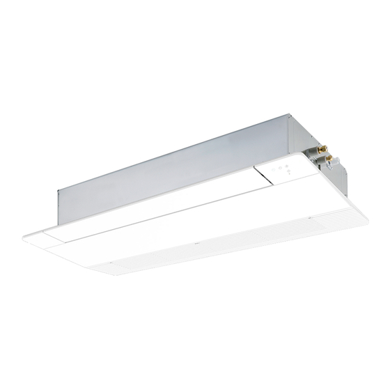
- Page 1 AIR CONDITIONER (MULTI TYPE) Installation Manual Indoor Unit For commercial use Model name: 1-way Cassette type MMU-UP0031YHP-E MMU-UP0051YHP-E MMU-UP0071YHP-E MMU-UP0091YHP-E MMU-UP0121YHP-E English...
-
Page 2: Table Of Contents
– 1 – Contents Original instruction Please read this Installation Manual carefully before installing the Air Conditioner. Precautions for safety ............3 •... - Page 3 Toshiba Carrier Corporation or, alternatively, he or she has been instructed in such matters by an individual or individuals who have been trained and is thus thoroughly acquainted with the knowledge related to this work.
-
Page 4: Precautions For Safety
– 3 – Precautions for safety Warning indications on the air conditioner unit The manufacturer shall not assume any liability for the damage Warning indication Description caused by not observing the description of this manual. WARNING WARNING WARNING ELECTRICAL SHOCK HAZARD ELECTRICAL SHOCK HAZARD Disconnect all remote General... - Page 5 • Only a qualified installer(*1) or qualified service person(*1) is • Do not move or repair any unit by yourself. There is high voltage allowed to undertake work at heights using a stand of 50 cm inside the unit. You may get electric shock when removing the or more or to remove the intake grille of the indoor unit to cover and main unit.
- Page 6 – 5 – • Follow the instructions in the Installation Manual to install the • Nitrogen gas must be used for the airtight test. air conditioner. Failure to follow these instructions may cause • The charge hose must be connected in such a way that it is not the product to fall down or topple over or give rise to noise, slack.
- Page 7 • Under no circumstances the power wire must not be extended. Explanations given to user Connection trouble in the places where the wire is extended • Upon completion of the installation work, tell the user where the may give rise to smoking and/or a fire. circuit breaker is located.
-
Page 8: Accessory Parts
– 7 – Accessory parts CAUTION Accessory parts New refrigerant air conditioner installation • This air conditioner adopts the new HFC refrigerant Part name Q’ty Shape Usage (R410A) which does not destroy ozone layer. (Hand over to customers) • The characteristics of R410A refrigerant are; easy to absorb Installation Manual This manual (For other languages that do not appear in this Installation... -
Page 9: Selection Of Installation Place
Selection of installation place Installation space (Unit: mm) Secure the specified space in the figure for installation and servicing. WARNING Install the air conditioner at enough strong place to withstand the weight of the unit. If the strength is not enough, the unit may fall down resulting in injury. Install the air conditioner at a height 2.5 m or more from the floor. -
Page 10: Installation
– 9 – Installation Opening a ceiling and Treatment of ceiling The ceiling differs according to structure of building. installation of hanging bolts For details, consult your constructor or interior finish CAUTION contractor. Consider the piping / wiring after the unit is hung In the process after the ceiling board has been Strictly comply with the following rules to prevent damage of the indoor units and human injury. - Page 11 Installation of ceiling panel Wireless type Installation of ceiling opening and Hanging bolt hanging bolt Level vial (Sold separately) (Sold separately) (levelness: 5 mm or less) Indoor unit Hanging bolt Install the ceiling panel according to Installation The sensor of indoor unit with wireless remote Manual attached with it after piping / wiring work has controller can receive a signal by distance within 30 mm...
-
Page 12: Drain Piping
– 11 – Drain piping Connecting drain pipe Check the draining For length of the traversing drain pipe, restrict to Connect a hard socket (locally procured) to the hard In the test run, check that water drain is properly CAUTION 20 m or less. -
Page 13: Refrigerant Piping
Refrigerant piping Test water drain while checking the operation sound of the drain pump motor. (If the operation sound changes from continuous Projection margin in flaring: B (Unit: mm) sound to intermittent sound, water is normally CAUTION drained.) Outer dia. of Conventional R410A tool used When the refrigerant pipe is long, provide support... -
Page 14: Electrical Connection
– 13 – Electrical connection Airtight test / Air purge, etc. Use the tightening torque levels as listed in the following table. For airtight test, air purge, addition of refrigerant, Outer dia. of WARNING and gas leak check, refer to the Installation Manual Tightening torque (N•m) connecting pipe (mm) attached to the outdoor unit. - Page 15 Power supply wire and communication wires specifications <In the case of combining with outdoor units of Super Modular Multi System u series (SMMS-u)> Uv line and Uc line (L2, L3, L4) Wire size : 1.0 to 1.5 mm² (Up to 1000 m) Power supply wire and communication wires are locally procured.
- Page 16 – 15 – Wire connection <In the case of combining with outdoor units other than Super Modular Multi System u series (SMMS-u)> Control wiring between indoor units, and outdoor unit (L2, L3) 1.25 mm² (Up to 1000 m) (2-core shield wire, non-polarity) Wire size : REQUIREMENT Central control line wiring (L1)
- Page 17 Remote controller wiring Address setup Strip off approx. 9 mm the wire to be connected. Set up the addresses as per the Installation Manual supplied with the outdoor unit. Wiring diagram Wiring on the ceiling panel Terminal block for remote controller Terminal block wiring of indoor unit According to the Installation Manual of the ceiling panel, connect the connector (20P: White) of the ceiling panel to...
-
Page 18: Applicable Controls
– 17 – Applicable controls Push the menu button to make Set data ] flash. Change Set data [ with [ ] setting button. REQUIREMENT When the air conditioner is used for the first time, Push OFF timer button. it will take some moments after the power has By doing so, the setup is completed. -
Page 19: Test Run
Test run Change of lighting time of Group control filter sign In a group control, a remote controller can control up Before test run to maximum 8 units. According to the installation condition, the lighting time For wiring procedure and wiring method of the of the filter sign (Notification of filter cleaning) can be Before turning on the circuit breaker, carry out the individual line (Identical refrigerant line) system, refer... -
Page 20: Maintenance
– 19 – Maintenance Wired remote controller Wireless remote controller (RBC-AX33UYP-E) Be sure to stop the air conditioner before making Use a vacuum cleaner to remove dust settings. CAUTION Test run (forced cooling operation) (Change the setup while the air conditioner is not from the filters or wash them with water. -
Page 21: Troubleshooting
Troubleshooting q Periodic Maintenance For environmental conservation, it is strongly recommended that the indoor and outdoor units of the air conditioner in use be cleaned and maintained regularly to ensure efficient operation of the air conditioner. When the air conditioner is operated for a long time, periodic maintenance (once a year) is recommended. If a problem occurs with the air conditioner, Furthermore, regularly check the outdoor unit for rust and scratches, and remove them or apply rustproof the OFF timer indicator alternately shows... - Page 22 – 21 – Check method On the wired remote controller, central control remote controller and the interface P.C. board of the outdoor unit (I/F), a check display LCD (Remote controller) or 7-segment display (on the outdoor interface P.C. board) to display the operation is provided.
- Page 23 Check code Wireless remote controller Outdoor unit 7-segment display Sensor block display of receiving unit Check code name Judging device Wired remote controller display Auxiliary code Operation Timer Ready Flash 01: TE1 sensor 02: TE2 sensor TE1,TE2 or TE3 sensor trouble 03: TE3 sensor 01: TL1 sensor 02: TL2 sensor...
- Page 24 – 23 – Check code Wireless remote controller Outdoor unit 7-segment display Sensor block display of receiving unit Check code name Judging device Wired remote controller display Auxiliary code Operation Timer Ready Flash ─ Model mismatch of indoor and outdoor unit ─...
- Page 25 Check code Wireless remote controller Outdoor unit 7-segment display Sensor block display of receiving unit Check code name Judging device Wired remote controller display Auxiliary code Operation Timer Ready Flash 01: Comp. 1 side 02: Comp. 2 side IPM short protection trouble Inverter 03: Comp.
-
Page 26: Specifications
Sound power level (dBA) Weight (kg) Model Main unit (Ceiling panel) Cooling Heating Manufacturer: TOSHIBA CARRIER (THAILAND) CO., LTD. 144 / 9 Moo 5, Bangkadi Industrial Park, Tivanon Road, Tambol Bangkadi, MMU-UP0031YHP-E 14 (4) Amphur Muang, Pathumthani 12000, Thailand MMU-UP0051YHP-E 14 (4) - Page 27 Warnings on Refrigerant Leakage Important Check of Concentration Limit 2) When there is an effective opening with the adjacent room for ventilation of leaking refrigerant gas (opening The room in which the air conditioner is to be installed requires a design that in the event of refrigerant without a door, or an opening 0.15% or larger than the respective floor spaces at the top or bottom of the gas leaking out, its concentration will not exceed a set limit.
- Page 28 – 27 – 53-EN 54-EN...
- Page 29 144 / 9 Moo 5, Bangkadi Industrial Park, Tivanon Road, Tambol Bangkadi, Amphur Muang, Pathumthani 12000, Thailand 1127650301...