Siemens SITRANS L Operating Instructions Manual
Radar transmitters with foundation fieldbus
Hide thumbs
Also See for SITRANS L:
- Operating instructions manual (228 pages) ,
- Compact operating instructions (114 pages) ,
- Application examples (11 pages)
Table of Contents
Advertisement
Quick Links
SITRANS LR250 with FOUNDATION FIELDBUS
SITRANS L
Radar Transmitters
SITRANS LR250 with FOUNDATION
FIELDBUS
Operating Instructions
7ML5431 (LR250)
7ML5432 (LR250 flanged encapsulated antenna)
7ML5433 (LR250 hygienic encapsulated antenna)
09/2021
A5E32221411-AH
Introduction
Safety information
Description
Installing/mounting
Connecting
Commissioning
Remote operation
Parameter reference
Service and maintenance
Diagnosing and
troubleshooting
Technical specifications
Dimension drawings
Appendix A: Technical
reference
Appendix B:
Communications via
Foundation Fieldbus
Appendix C: Product
documentation and
support
List of abbreviations
LCD menu structure
1
2
3
4
5
6
7
8
9
10
11
12
A
B
C
13
14
Advertisement
Table of Contents

Related Manuals for Siemens SITRANS L


Summary of Contents for Siemens SITRANS L
- Page 1 SITRANS LR250 with FOUNDATION FIELDBUS Introduction Safety information SITRANS L Description Installing/mounting Radar Transmitters SITRANS LR250 with FOUNDATION FIELDBUS Connecting Commissioning Operating Instructions Remote operation Parameter reference Service and maintenance Diagnosing and troubleshooting Technical specifications Dimension drawings Appendix A: Technical...
- Page 2 Note the following: WARNING Siemens products may only be used for the applications described in the catalog and in the relevant technical documentation. If products and components from other manufacturers are used, these must be recommended or approved by Siemens. Proper transport, storage, installation, assembly, commissioning, operation and maintenance are required to ensure that the products operate safely and without any problems.
-
Page 3: Table Of Contents
Table of contents Introduction ............................9 LR250 FF manual usage ....................... 9 Purpose of this documentation .................... 9 Revision history ........................9 Industrial use note ......................10 Checking the consignment ....................10 Security information ......................10 Transportation and storage ....................11 Notes on warranty ...................... - Page 4 Table of contents 4.3.1 Nozzle design ........................26 4.3.2 Nozzle location ........................27 4.3.3 Orientation in a vessel with obstructions ................29 4.3.4 Mounting on a Stillpipe or Bypass Pipe ................29 4.3.5 Device orientation ......................30 Installation instructions ...................... 30 4.4.1 Threaded versions ......................
- Page 5 Table of contents 7.1.3.1 Electronic Device Description (EDD) ................... 68 7.1.4 Master Reset ........................70 7.1.5 Scan Device ........................70 7.1.6 Sensor calibration ......................70 7.1.7 Configuring a new device....................71 7.1.7.1 Quick Start Wizard via AMS Device Manager ............... 71 7.1.8 Changing parameter settings using AMS Device Manager ...........
- Page 6 Table of contents Maintenance and repair work................... 166 9.3.1 Unit repair and excluded liability ..................167 9.3.2 Part replacement ......................167 Disposal ........................... 169 Return procedure ......................169 Diagnosing and troubleshooting ....................... 170 10.1 Device status icons ......................171 10.2 General fault codes ......................
- Page 7 Table of contents 12.18 Hygienic encapsulated antenna (DN80 aseptic slotted nut to DIN 11864-1) ...... 211 12.19 Hygienic encapsulated antenna (DN100 aseptic slotted nut to DIN 11864-1) ....212 12.20 Hygienic encapsulated antenna (DN50 aseptic flange to DIN 11864-2) ......213 12.21 Hygienic encapsulated antenna (DN80 aseptic flange to DIN 11864-2) ......
- Page 8 Table of contents Appendix B: Communications via Foundation Fieldbus ..............253 Field Communicator 375 (F375) ..................253 Appendix C: Product documentation and support ................254 Product documentation ....................254 Technical support ......................255 List of abbreviations .......................... 256 LCD menu structure ........................... 257 Glossary .............................
-
Page 9: Introduction
We always welcome suggestions and comments about manual content, design, and accessibility. Please direct your comments to: Technical publications (pi-documentation-service.industry@siemens.com) Purpose of this documentation These instructions contain all information required to commission and use the device. Read the instructions carefully prior to installation and commissioning. -
Page 10: Industrial Use Note
In order to protect plants, systems, machines and networks against cyber threats, it is necessary to implement – and continuously maintain – a holistic, state-of-the-art industrial security concept. Siemens’ products and solutions constitute one element of such a concept. SITRANS LR250 with FOUNDATION FIELDBUS... -
Page 11: Transportation And Storage
The sales contract contains all obligations on the part of Siemens as well as the complete and solely applicable warranty conditions. Any statements regarding device versions described in the manual do not create new warranties or modify the existing warranty. -
Page 12: Safety Information
Safety information Preconditions for safe use This device left the factory in good working condition. In order to maintain this status and to ensure safe operation of the device, observe these instructions and all the specifications relevant to safety. Observe the information and symbols on the device. Do not remove any information or symbols from the device. -
Page 13: Fcc Conformity
Safety information 2.1 Preconditions for safe use 2.1.3 FCC Conformity US Installations only: Federal Communications Commission (FCC) rules Note • This device has been tested and found to comply with the limits Class B digital device part 15 of the FCC Rules. These limits are designed to provide reasonable protection against harmful interference when the equipment is operated in a commercial environment. -
Page 14: Industry Canada Conformity Note
Safety information 2.1 Preconditions for safe use 2.1.5 Industry Canada conformity note Note • This device has been tested and found to comply with the limits RS- 211 - Level Probing Radar Equipment. These limits are designed to provide reasonable protection against harmful interference when the equipment is operated in a commercial environment. -
Page 15: Conformity With Uk Regulations
Safety information 2.1 Preconditions for safe use 2.1.7 Conformity with UK regulations The UKCA marking on the device symbolizes the conformity with the following UK regulations: Electromagnetic compatibility Electromagnetic Compatibility Regulations EMC SI 2016/1091 2016 Low Voltage LVD SI 2016/1101 Electrical Equipment (Safety) Regulations 2016 Explosive atmosphere UKEX SI 2016/1107... -
Page 16: Improper Device Modifications
If you need additional information not covered by these instructions, contact your local Siemens office or company representative. Note Operation under special ambient conditions... -
Page 17: Use In Hazardous Areas
Safety information 2.4 Use in hazardous areas Use in hazardous areas Qualified personnel for hazardous area applications Persons who install, connect, commission, operate, and service the device in a hazardous area must have the following specific qualifications: • They are authorized, trained or instructed in operating and maintaining devices and systems according to the safety regulations for electrical circuits, high pressures, aggressive, and hazardous media. -
Page 18: Description
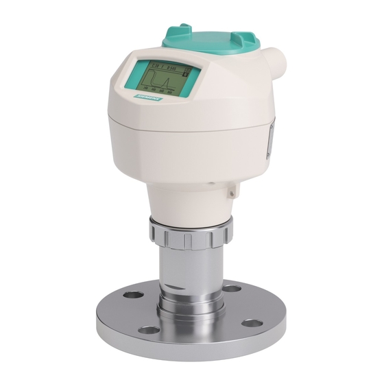
Description SITRANS LR250 overview WARNING Loss of protection Danger to personnel, system and environment can result from improper use of the device. • SITRANS LR250 is to be used only in the manner outlined in this manual, otherwise protection provided by the device may be impaired. SITRANS LR250 is a 2-wire 25 GHz pulse radar level transmitter for continuous monitoring of liquids and slurries in storage vessels including high pressure and high temperature, to a range of 20 meters (66 feet). -
Page 19: Programming
This device is very easy to install and configure via a graphical local user interface (LUI). You can modify the built in parameters either locally via the Siemens infrared handheld programmer, or from a remote location using one of the following options: •... -
Page 20: Approvals And Certificates
Description 3.4 Approvals and certificates Approvals and certificates Note For further details see Approvals (Page 183). SITRANS LR250 is available with approvals for General purpose, sanitary or hygienic and for hazardous areas. In all cases, check the nameplate on your device, and confirm the approval rating. -
Page 21: Installing/Mounting
Note Material compatibility Siemens can provide you with support concerning selection of parts wetted by process media. However, you are responsible for the selection of parts. Siemens accepts no liability for faults or failures resulting from incompatible materials. WARNING Unsuitable connecting parts Risk of injury or poisoning. -
Page 22: Unsuitable Cables, Cable Glands And/Or Plugs
Installing/mounting 4.1 Basic safety information 4.1.1 Unsuitable cables, cable glands and/or plugs WARNING Unsuitable cables, cable glands and/or plugs Risk of explosion in hazardous areas. • Use only cable glands/plugs that comply with the requirements for the relevant type of protection. -
Page 23: Pressure Equipment Directive, Ped, 2014/68/Eu
4.1.2.1 Pressure Equipment Directive, PED, 2014/68/EU Siemens Level Transmitters with flanged, threaded, or sanitary clamp type process mounts have no pressure-bearing housing of their own and, therefore, do not come under the Pressure Equipment Directive as pressure or safety accessories (see EU Commission Guideline A-08 and A-20). -
Page 24: Installation Location Requirements
Installing/mounting 4.2 Installation location requirements Installation location requirements WARNING Aggressive atmospheres Danger to personnel, system and environment can result from unsuitable environment. • Provide an environment suitable to the housing rating and materials of construction. NOTICE Direct sunlight Damage to device. The device can overheat or materials become brittle due to UV exposure. -
Page 25: Proper Mounting
Installing/mounting 4.3 Proper mounting PTFE flanged encapsulated -40 to +80 °C -40 to +170 °C (-40 to +176 °F) (-40 to +338 °F) Hygienic encapsulated -40 to +80 °C -40 to +170 °C (-40 to +176 °F) (-40 to +338 °F) with FKM seals used on process connection: -20 to +170 °C (-4 to +338 °F) with EPDM seals used on process connection:... -
Page 26: Nozzle Design
Installing/mounting 4.3 Proper mounting 4.3.1 Nozzle design Threaded PVDF antenna Stainless steel horn antenna Polymeric lens versions Hygienic encapsulated antenna (HEA) ① Minimum clearance: 10 mm (0.4") ② Minimum diameter: 50 mm (2") ③ Maximum nozzle length ④ Maximum length/diameter ratio 1:1 •... -
Page 27: Nozzle Location
Installing/mounting 4.3 Proper mounting 4.3.2 Nozzle location • Avoid central locations on tall, narrow vessels • Nozzle must be vertical and clear of imperfections Preferred Undesirable Beam angle Note • Beam width depends on antenna size and is approximate: see below. •... - Page 28 Installing/mounting 4.3 Proper mounting Antenna type Antenna size Beam angle 3" 10° 4" 8° Threaded PVDF 19° Process connection Process connection type size PTFE flanged encapsulated 2" Class 150 ASME B16.5 12.8° 3, 4, 6" Class 150 ASME B16.5 9.6° 10K JIS B 2220 12.8°...
-
Page 29: Orientation In A Vessel With Obstructions
Installing/mounting 4.3 Proper mounting 4.3.3 Orientation in a vessel with obstructions Polarization reference point For best results on a vessel with obstructions, or a stillpipe with openings, orient the front or back of the device toward the obstructions. For an illustration, see Device orientation (Page 30). -
Page 30: Device Orientation
Installing/mounting 4.4 Installation instructions Hygienic encapsulated antenna 50 to 100 mm (2 to 4") Not recommended: > 100 mm (4") Bypass vent: Required at the upper end of the bypass To equalize pressure and keep the liquid level in the bypass constant with the liquid level in the vessel. - Page 31 Installing/mounting 4.4 Installation instructions WARNING Improper installation Danger to personnel, system and environment can result from improper installation. • Installation shall only be performed by qualified personnel and in accordance with local governing regulations. NOTICE Device handling Damage to device may result from improper handling. •...
-
Page 32: Threaded Versions
Installing/mounting 4.4 Installation instructions Note • On devices with a removable head, there is no limit to the number of times a device can be rotated without damage. • When mounting, orient the front or back of the device towards the closest vessel wall or obstruction. - Page 33 Installing/mounting 4.4 Installation instructions Flange bolting: recommended torque Pressure class Nominal pipe size Number of bolts Recommended torque (NPS) (Nm) ASME B16.5, Class 150 2" 30 – 50 3" 50 – 70 4" 40 – 60 6" 70 – 90 EN1092-1, PN16 / DN50/50A 30 –...
-
Page 34: Hygienic Versions
Installing/mounting 4.4 Installation instructions Recommendations for flange bolting: • Check bolts periodically, re-torque as required. • Use new lens, O-ring and spring washers after removal from installation. For instructions on replacing the lens, see Part replacement (Page 167). See Flanged Horn with extension (Page 196), Raised-Face Flange per EN 1092-1 (Page 225), Flat-Face Flange (Page 227), and PTFE Flanged encapsulated antenna (3"/DN80/80A sizes and larger) (Page 202) for dimensions. -
Page 35: Disassembly
Installing/mounting 4.5 Disassembly ① Orientation mark for leak detection port ② Leak detection port Disassembly DANGER Pressure applications Danger to personnel, system and environment will result from improper disassembly. • Never attempt to loosen, remove, or disassemble process connection while vessel contents are under pressure. -
Page 36: Connecting
Connecting Basic safety information NOTICE Condensation in the device Damage to device through formation of condensation if the temperature difference between transportation or storage and the mounting location exceeds 20 °C (36 °F). • Before taking the device into operation, let the device adapt for several hours in the new environment. - Page 37 Connecting 5.2 Connecting SITRANS LR250 WARNING Loss of protection Loss of approvals can result from improper connection. • Check the nameplate on your device, to verify the approval rating. • Use appropriate cable entry seals to maintain IP or NEMA rating. •...
- Page 38 Connecting 5.2 Connecting SITRANS LR250 6. Ground the device according to local regulations. 7. Tighten the gland to form a good seal. 8. Close the lid and secure the locking screw before programming and device configuration. Note Lid-lock set screw not applicable to 3-A Sanitary approved device. Note •...
-
Page 39: Wiring Setups For Hazardous Area Installation
Connecting 5.3 Wiring setups for hazardous area installation Configuration via Linking Device ① Controller ⑤ HSE/H1 Linking Device ② FF (HSE) ⑥ FF (H1) ③ Configurator software ⑦ LR250 FF ④ PC/laptop Configuration via PCI/PCMCIA Card ① Configurator software ④ H1 Interface ②... -
Page 40: Configuration With Foundation Fieldbus For Hazardous Areas
Connecting 5.3 Wiring setups for hazardous area installation In all cases, check the nameplate on your instrument, confirm the approval rating, and perform installation and wiring according to your local safety codes. 5.3.1 Configuration with Foundation Fieldbus for hazardous areas Configuration via Gateway ①... -
Page 41: Intrinsically Safe Wiring
The ATEX and UKEX certificates listed on the nameplate can be downloaded from our website: Product page (http://www.siemens.com/LR250) Go to Support > Approvals / Certificates. The IECEx certificate listed on the nameplate can be viewed on the IECEx website. Go to: IECEx (http://iecex.iec.ch/) -
Page 42: Intrinsically Safe Wiring (Fm/Csa)
FISCO Concept Note Connection drawing For complete details and instructions regarding the FISCO Concept, see the FM/CSA connection drawing which can be downloaded from the Siemens Industry Image Database: SITRANS LR250 Foundation Fieldbus connection drawing (A5E02358161) (http://www.automation.siemens.com/bilddb/index.aspx?gridview=view2&objkey=G_FI01_X X_11098&showdetail=true&view=Search) SITRANS LR250 with FOUNDATION FIELDBUS... -
Page 43: Non-Sparking Wiring
(internal capacitance) Ci (internal inductance) Li 5.3.3 Non-sparking wiring The ATEX and UKEX certificates listed on the nameplate can be downloaded from our website: Product page (http://www.siemens.com/LR250) Go to: Support > Approvals/Certificates. SITRANS LR250 with FOUNDATION FIELDBUS Operating Instructions, 09/2021, A5E32221411-AH... -
Page 44: Non-Incendive Wiring (Us/Canada Only)
IP67, IP68 locations. 5.3.4 Non-incendive wiring (US/Canada only) FM/CSA Class 1, Div 2 connection drawing number 23650673 can be downloaded from Siemens Industry Image Database: FM/CSA Class 1, Div 2 connection drawing 23650673 (http://www.automation.siemens.com/bilddb/index.aspx?gridview=view2&objkey=G_FI01_X X_03551&showdetail=true&view=Search) • For wiring requirements: follow local regulations. - Page 45 Connecting 5.4 Instructions specific to hazardous area installations 7. Installation and inspection of this equipment shall be carried out by suitably trained personnel in accordance with the applicable code of practice (EN 60079-14 and EN 60079- 17 in Europe and the UK). 8.
-
Page 46: Commissioning
Commissioning Basic safety information WARNING Loss of explosion protection Risk of explosion when device is not properly commissioned If opening device • Isolate from power. - or - • Ensure that the atmosphere is explosion-free (hot work permit). Ensure device is properly closed before returning to operation. Operating via the handheld programmer The handheld programmer used with this device contains lithium batteries that are non- replaceable. -
Page 47: Power Up
6.2.1 Power up Power up the device. A transition screen showing first the Siemens logo and then the current firmware revision is displayed while the first measurement is being processed. SITRANS LR250 automatically starts up in Measurement mode. The first time the device is configured, you will be prompted to select a language (English, German, French, Spanish or Chinese).To... -
Page 48: The Lcd Display
Commissioning 6.2 Operating via the handheld programmer 6.2.2.1 The LCD display Measurement mode display Normal operation ① toggle indicator for analog input function blocks (AIFB 1/AIFB 2, displayed as FB1/FB2) ② identifies which block is source of displayed value ③ Measured value (level, space, distance, or volume) ④... -
Page 49: Handheld Programmer (Part No. 7Ml1930-1Bk)
Commissioning 6.2 Operating via the handheld programmer PROGRAM mode display Navigation view ① Item band ④ Current item number ② Menu bar ⑤ Current item ③ Current menu • A visible menu bar indicates the menu list is too long to display all items. •... -
Page 50: Programming
Commissioning 6.2 Operating via the handheld programmer Key functions in measurement mode Function Result Updates internal enclosure temperature reading. New value is displayed in LCD secondary re- Updates echo confidence value. gion. Updates distance measurement. Mode opens PROGRAM mode. Opens the menu level last displayed in this power cycle, unless power has been cycled since exiting PROGRAM mode or more than 10 minutes have elapsed since PROGRAM... - Page 51 Commissioning 6.2 Operating via the handheld programmer Parameter menus Note For the complete list of parameters with instructions, see Parameter reference (Page 120). Parameters are identified by name and organized into function groups. See LCD menu structure (Page 257). 1. QUICK START 2.
- Page 52 Commissioning 6.2 Operating via the handheld programmer Name Menu level Function UP or DOWN menu or pa- Scroll to previous or next menu or param- arrow rameter eter RIGHT arrow menu Go to first parameter in the selected menu, or open next menu. parameter Open Edit mode.
- Page 53 Commissioning 6.2 Operating via the handheld programmer • Key in a new value. • Press RIGHT arrow to accept it. Press RIGHT arrow to accept it.The LCD returns to parameter view and displays the new selection. ① Parameter name ② Parameter number ③...
-
Page 54: Quick Start Wizard Via The Handheld Programmer_Note
Commissioning 6.2 Operating via the handheld programmer Name Function Plus or minus Numeric Changes the sign of the entered value. sign editing Numeral Numeric Enters the corresponding character. editing 6.2.3.2 Quick Start Wizard via the handheld programmer_note Note • A reset to factory defaults should be performed before running the Quick Start Wizard if the device has been used in a previous application. - Page 55 Commissioning 6.2 Operating via the handheld programmer Material Selects the appropriate echo processing algorithms for the material [see Position Detect (2.5.7.2.) for more detail]. Options LIQUID LIQUID LOW DK (low dielectric liquid – CLEF algorithm enabled) dK < 3.0 Response rate Sets the reaction speed of the device to measurement changes in the target range.
- Page 56 Commissioning 6.2 Operating via the handheld programmer Operation Operation Description NO SERVICE Measurement and associated loop current are not updated, and the device defaults to Fail-safe mode LEVEL Distance to material surface referenced from Low calibration point SPACE Distance to material surface referenced from High calibration point DISTANCE Distance to material surface referenced from Sensor reference point See Material Level (2.3.5.) for more detail.
-
Page 57: Auto False Echo Suppression
Commissioning 6.2 Operating via the handheld programmer High calibration point Distance from Sensor Reference Point to High Calibration Point: usually process full level. (See Operation for an illustration.) Values Range: 0.00 to 20.00 m Wizard complete Options BACK, CANCEL, FINISH (Display returns to 1.1 Quick Start Wiz menu when Quick Start is successfully completed.) Press DOWN arrow (Finish). -
Page 58: Device Address
Commissioning 6.3 Application examples ① Confidence ⑦ Zoom ② Distance from Low Calibration Point to vertical cross-hair ⑧ Measure ③ Algorithm: tF (trueFirst) ⑨ Exit ④ Distance from flange face to target ⑩ Exit icon selected ⑤ Pan left/right - selected ⑪... -
Page 59: Liquid Resin In Storage Vessel, Level Measurement
Commissioning 6.3 Application examples You can use these examples as setup references. Enter the values in the parameter tables to select the corresponding functions. Configure the basic settings using the Quick Start wizard parameters. (These parameters are inter-related, and changes take effect only after you select FINISH in final step: Wizard Complete.) In each example, after performing a Quick Start, navigate to the other required parameters (either via the handheld programmer or via AMS Device Manager) and enter the appropriate... -
Page 60: Horizontal Vessel With Volume Measurement
Commissioning 6.3 Application examples Parameter Parameter No. /Name Options/ Function type Values Quick Start Introduction NEXT Continue with Wizard. Wizard param- NEXT Language Continue with current eters language. LIQUID Material Response Rate Medium =1 m/minute Units meters Low Calibration Point 5 m (16.4 ft) High Calibration Point 0.5 m (1.64 ft) - Page 61 Commissioning 6.3 Application examples ① Sensor reference point ⑥ A = 0.8 m ② 0.5 m ⑦ L = 6 m ③ High calibration point ⑧ 100% = 8000 L ④ 3.5. m ⑨ Volume reading ⑤ Low calibration point Parameter type Parameter Name Options/...
-
Page 62: Application With Stillpipe
Commissioning 6.3 Application examples 6.3.3 Application with stillpipe A stillpipe is recommended for products with a dK of less than 3, or if extremely turbulent or vortex conditions exist. This mounting arrangement can also be used to provide optimum signal conditions on foaming materials. Note •... - Page 63 Commissioning 6.3 Application examples Parameter Parameter No./Name Options/Values Function type Response Rate Medium =1 m/minute Units meters Operating mode LEVEL Level is reported as Volume when a vessel shape is selected. Low Calibration Point 5 m (16.4 ft) High Calibration Point 0.5 m (1.64 ft) FINISH Wizard Complete...
- Page 64 Commissioning 6.3 Application examples Note Flanged and Hygienic encapsulated antenna For Flanged encapsulated antenna (7ML5432) and Hygienic encapsulated antenna (7ML5433) match the process connection size to the pipe diameter. For example, DN 80/3" flange to DN 80/3" pipe. SITRANS LR250 with FOUNDATION FIELDBUS Operating Instructions, 09/2021, A5E32221411-AH...
-
Page 65: Remote Operation
Remote operation Operating via AMS Device Manager AMS Device Manager is a software package that monitors the process values, alarms and status signals of the device. Please consult the operating instructions or online help for details on using AMS Device Manager. You can find more information at: Emerson (http://www.emersonprocess.com/AMS/) 7.1.1 Functions in AMS Device Manager... -
Page 66: Key Features Of Ams Device Manager Rev. 9.0
Remote operation 7.1 Operating via AMS Device Manager • Diagnostic Block (DIAG) • Resource Block (RESOURCE) ① Active function group ② Blocks within each function group ③ Functions groups available In general, process parameters are accessed through the Level Transducer Block, and device parameters are accessed through the Resource Block. -
Page 67: Pull-Down Menu Access
Remote operation 7.1 Operating via AMS Device Manager CONFIGURE/SETUP function group Block Feature Function Linearization (LTB) (Page 79) Volume measurement in an irregular vessel Maintenance & Diagnostics (LTB) Set schedules and reminders for sensor (Page 85) maintenance and service RESOURCE Quick Start Wizard via AMS Device Device configuration for simple applications Manager (Page 71) -
Page 68: Adding A New Device
SITRANS LR250 requires the EDD for AMS Device Manager version 9.0. Check the product page of our website at: www.siemens.com/LR250 (http://www.siemens.com/LR250), under Downloads, for the latest version of EDD: SITRANS LR250 FF - Foundation Fieldbus - AMS V9.0. 1. Check that you have the latest version of the EDD for AMS Device Manager that matches the firmware revision of your device. - Page 69 Remote operation 7.1 Operating via AMS Device Manager 3. Double-click the device icon to open the startup screen. The startup screen shows device identification details, and a navigation window on the left-hand side of the screen. (The Block Status will show Out of Service at initial startup.) 4.
-
Page 70: Master Reset
Remote operation 7.1 Operating via AMS Device Manager 7.1.4 Master Reset A master reset is recommended before first configuring a new device. (Block Status must be Out of Service to perform a Master Reset.) 1. Navigate to Configure/Setup > Resource > Operation > Methods and click to open the dialog window. -
Page 71: Configuring A New Device
Remote operation 7.1 Operating via AMS Device Manager 7.1.7 Configuring a new device Configure a new device using the Quick Start Wizard, found in the Resource Block of the function group Configure/Setup. 7.1.7.1 Quick Start Wizard via AMS Device Manager The Quick Start Wizard groups together all the settings you need to configure a device for most applications. - Page 72 Remote operation 7.1 Operating via AMS Device Manager Step 1 - Identification You can accept the default values without modification. (Descriptor, Message, and Installation Date fields can be left blank.) If desired, make changes then click on Apply. (The Apply button is activated when a parameter is modified.) Go to Step 2. Step 2 - Application Type Click on Step 2 - Application Type in the navigation window.
- Page 73 Remote operation 7.1 Operating via AMS Device Manager Step 3 - Vessel Shape Click on Step 3 - Vessel Shape in the navigation window. Select the vessel shape. To describe a more complex shape, select Linearization Table in the Vessel Shape field and see Linearization (LTB) (Page 79) for more details.
-
Page 74: Changing Parameter Settings Using Ams Device Manager
Remote operation 7.1 Operating via AMS Device Manager Step 5 - Summary Click on Step 5 - Summary in the navigation window. Check parameter settings. Return to individual steps if further changes are necessary. The Quick Start Wizard is now complete. 7.1.8 Changing parameter settings using AMS Device Manager Note... -
Page 75: Operation (Ltb)
Remote operation 7.1 Operating via AMS Device Manager Identification: • TAG: Read only. Description for the associated block: device tag prefixed by block type. • Descriptor [see Descriptor (2.1.2.)] • Transducer Block Type: Read only. Identifies the type of transducer block. •... - Page 76 Remote operation 7.1 Operating via AMS Device Manager Click on Simulation to open the dialog window for access to: Simulation (Input) Allows you to simulate the sensor value which is input to the Level Transducer Block. This tests everything between the Level Transducer Block and Output. Note To activate simulation via AMS Device Manager or the 375 Field Communicator, simulation must also be set to Enabled on the device.
-
Page 77: Setup (Ltb)
Remote operation 7.1 Operating via AMS Device Manager 1. To enable simulation select Fixed value or Ramp in the Simulation field. 2. If you select Fixed value, enter a Simulation Value. 3. If you select Ramp, enter the ramp start, end, number of steps, and steplength. 4. - Page 78 Remote operation 7.1 Operating via AMS Device Manager Navigate to Configure/Setup > LTB > Setup and click on Sensor for access to: General [see Sensor (2.3.) for details] • Unit [see Unit (2.3.1.)] • Level Unit [see Level Unit (2.3.2.)] •...
-
Page 79: Linearization (Ltb)
Remote operation 7.1 Operating via AMS Device Manager 7.1.9.4 Linearization (LTB) You can use the linearization feature to define a more complex vessel shape and enter up to 32 level breakpoints where the corresponding volume is known. See Linearization (2.4.). Navigate to Configure/Setup >... -
Page 80: Signal Processing
Remote operation 7.1 Operating via AMS Device Manager 1. The default for level values is percent: if you want to select units instead, go to Configure/Setup > LTB > Setup > Sensor > Level Unit, and select the desired unit. 2. - Page 81 Remote operation 7.1 Operating via AMS Device Manager General Navigate to Configure/Setup > LTB > Setup > Signal Processing and click on General for access to: Range [see Signal Processing (2.5.)] • Near Range [see Near Range (2.5.1.)] • Far Range [see Far Range (2.5.2.)] •...
- Page 82 Remote operation 7.1 Operating via AMS Device Manager Sampling [see Sampling (2.5.8.)] • Echo Lock [see Echo Lock (2.5.8.1.)] • Sampling Up [see Up Sampling (2.5.8.2.)] • Sampling Down [see Down Sampling (2.5.8.3.)] Echo Quality [see Echo Quality (2.5.9.)] • Confidence [see Confidence (2.5.9.1.)] •...
- Page 83 Remote operation 7.1 Operating via AMS Device Manager TVT Shaper [see TVT Shaper (2.5.11.)] • Breakpoints 1 to 40 • Shaper Mode 1. Open the menu Configure/Setup > LTB > Setup > Signal Processing > TVT and click on the TVT Setup tab 2.
- Page 84 Remote operation 7.1 Operating via AMS Device Manager Echo Profile Displays the current echo profile. Navigate to Configure/Setup > LTB > Setup > Signal Processing and click on Echo Profile to view the current echo profile and to access: Echo Profile Parameters [see Echo Profile (3.1.)] •...
-
Page 85: Maintenance & Diagnostics (Ltb)
Remote operation 7.1 Operating via AMS Device Manager 7.1.9.6 Maintenance & Diagnostics (LTB) Note For more detailed explanations of the parameters listed below see the pages referenced. Navigate to Configure/Setup > LTB > Maintenance and Diagnostics for access to: Remaining Sensor Lifetime [see Remaining Sensor LIfetime (4.3.)] •... - Page 86 Remote operation 7.1 Operating via AMS Device Manager Service Schedule [see Service Schedule (4.4.)] • Service Interval [see Service Interval (4.4.1.)] • Time Since Last Service [see Time Since Last Service (4.4.2.)] • Time Until Next Service [see Time Until Next Service (4.4.3.)] •...
-
Page 87: Communication (Ltb)
Remote operation 7.1 Operating via AMS Device Manager Electronics Temperature [see Electronics Temperature (3.3.)] • Electronics Temperature: Displays the current internal temperature of the device • Minimum Value [see Minimum Value (3.3.1.)] • Maximum Value [see Maximum Value (3.3.2.)] 7.1.9.7 Communication (LTB) Navigate to Configure/Setup >... -
Page 88: Configure/Setup (Liquid Crystal Display Block-Lcd)
Remote operation 7.1 Operating via AMS Device Manager Communication: • Static Revision No. [see Static Revision Number (2.6.1.)] 7.1.10 Configure/Setup (Liquid Crystal Display Block-LCD) 7.1.10.1 Identification (LCD) Navigate to Configure/Setup > LCD > Identification. Identification: • TAG • Descriptor • Transducer Block Type •... -
Page 89: Operation (Lcd)
Remote operation 7.1 Operating via AMS Device Manager 7.1.10.2 Operation (LCD) Note For more detailed explanations of the parameters listed below see the pages referenced. Navigate to Configure/Setup > LCD > Operation. Click on Block Modes to open the dialog window for access to: Block Modes: •... -
Page 90: Communication (Lcd)
Remote operation 7.1 Operating via AMS Device Manager Language [see Language (7.)] LCD Fast Mode [see LCD Fast Mode (4.9.)] LCD Contrast [see LCD Contrast (4.10.)] Local Operation [see Local Operation (6.2.3.)] If local operation is disabled remotely and no communication activity exists for 30 seconds, the parameter is made visible again locally. -
Page 91: Operation (Diag)
Remote operation 7.1 Operating via AMS Device Manager Identification: • TAG • Descriptor • Transducer Block Type • Strategy • Plant Unit Note For descriptions of Identification parameters see Identification (LTB) (Page 74). 7.1.11.2 Operation (DIAG) Navigate to Configure/Setup > DIAG > Operation. Block Modes: •... -
Page 92: Identification (Resource)
Remote operation 7.1 Operating via AMS Device Manager 7.1.12.1 Identification (RESOURCE) Navigate to Configure/Setup > RESOURCE > Identification for access to: Identification • TAG: Read only. Description for the associated block: device tag prefixed by block type. • Descriptor [see Descriptor (2.1.2.)] •... -
Page 93: Wizards (Resource)
Remote operation 7.1 Operating via AMS Device Manager 7.1.12.2 Wizards (RESOURCE) Navigate to Configure/Setup > RESOURCE > Wizards > Quick Start for access to Quick Start steps [see Quick Start Wizard via AMS Device Manager (Page 71)]. 7.1.12.3 Operation (RESOURCE) Navigate to Configure/Setup >... - Page 94 Remote operation 7.1 Operating via AMS Device Manager 1. Ensure the Block Status is Out of Service. 2. Click the Master Reset button, then click Next to perform a reset. 3. Select the Reset Type Note The following parameters are not reset by any reset type: Write Protection, PIN to Unlock, Auto False Echo Suppression Range, Learned TVT.
-
Page 95: Maintenance & Diagnostics (Resource)
Remote operation 7.1 Operating via AMS Device Manager 7.1.12.4 Maintenance & Diagnostics (RESOURCE) Navigate to Configure/Setup > RESOURCE > Maintenance & Diagnostics for access to: Remaining Device Lifetime [see Remaining Device Lifetime (4.2.)] • Lifetime (expected) [see Lifetime (expected (4.2.1.)] •... -
Page 96: Communication (Resource)
Remote operation 7.1 Operating via AMS Device Manager • Reminder 1 before Calibration (Required) [see Reminder 1 before Calibration (Required) (4.5.5.)] • Reminder 2 before Calibration (Demanded) [see Reminder 2 before Calibration (Demanded) (4.5.6.)] • Click on Calibration Performed to reset Time Since Last Calibration to 0 hours. Wear •... -
Page 97: Security (Resource)
Remote operation 7.1 Operating via AMS Device Manager • ITK Version [see ITK Version (5.6.)] • Static Revision No. [see Static Revision Number ( 2.6.1.)] 7.1.12.6 Security (RESOURCE) Navigate to Configure/Setup > RESOURCE > Security to access: Local Access • Local Write Protected [see Write Protection (6.2.1.)] •... -
Page 98: Device Diagnostics (Level Transducer Block - Ltb)
Remote operation 7.1 Operating via AMS Device Manager 7.1.13 Device Diagnostics (Level Transducer Block - LTB) Note For explanations of the alarms and errors listed below, see Parameter Description charts for the respective block in manual Foundation Fieldbus for Level Instruments (7ML19985MP01). 7.1.13.1 Alarms &... - Page 99 Remote operation 7.1 Operating via AMS Device Manager Maintenance • Maintenance Required • Maintenance Demanded Information • Simulation Active • Local Override • Power Up • Out of Service XD Error • Transducer Error Click on Block Alarm to open the dialog window to read the following: Unacknowledged •...
- Page 100 Remote operation 7.1 Operating via AMS Device Manager 1. From the Block Error tab, check the Maintenance window to display the level of maintenance alarm that is active. 2. From the Block Alarm tab, check the Alarm State window to display the level of maintenance alarm that has been acknowledged.
-
Page 101: Extended Diagnostics (Ltb)
Remote operation 7.1 Operating via AMS Device Manager Note Acknowledging a maintenance reminder from the device (see Acknowledge (4.2.9.), (4.3.9.), (4.4.9.), (4.5.9.) will not set the Block Alarm to Acknowledged in AMS. The maintenance alarm will cause an FF block alert, and the block alert can only be acknowledged via a remote host such as NI-FBUS Configurator or AMS Device Manager (as in step 3 above). -
Page 102: Device Diagnostics (Liquid Crystal Display Block - Lcd)
Remote operation 7.1 Operating via AMS Device Manager 7.1.14 Device Diagnostics (Liquid Crystal Display Block - LCD) 7.1.14.1 Alarms & Errors (LCD) Navigate to Device Diagnostics > LCD > Alarms & Errors to read Block and Alarm errors. [Errors displayed are the same for each block (LTB, LCD, DIAG, RESOURCE). See Alarms & Errors (LTB) (Page 98) for full listing.] 7.1.15 Device Diagnostics (Diagnostic Transducer Block - DIAG) - Page 103 Remote operation 7.1 Operating via AMS Device Manager Information • Simulation Active • Local Override • Power Up • Out of Service Click on Block Alarm tab to open the dialog window to read the following: Unacknowledged • Unacknowledged Alarm State •...
-
Page 104: Extended Diagnostics (Resource)
Remote operation 7.1 Operating via AMS Device Manager 7.1.16.2 Extended Diagnostics (RESOURCE) Navigate to Device Diagnostics > RESOURCE > Extended Diagnostics to read the following: Detailed Error Info • Device Lifetime Limit1 • Device Lifetime Limit2 • Calibration Schedule Limit1 •... -
Page 105: Process Variables (Level Transducer Block - Ltb)
Remote operation 7.1 Operating via AMS Device Manager • BC Start • BC Stop • BC Duration • CPU Fault • Data Bus • Addr Bus • Spurious SW Interrupt • Spurious HW Interrupt • Time Base Failure 7.1.17 Process Variables (Level Transducer Block - LTB) To compare outputs in real time navigate to Process Variables >... -
Page 106: Password Protection
Remote operation 7.1 Operating via AMS Device Manager Trend Values • Level/Volume (PV) The primary variable and the channel 1 output from the transducer block. Click on Echo Profile to open the dialog window to read the following: Echo Profile •... - Page 107 Remote operation 7.1 Operating via AMS Device Manager An AMS Device Manager administrator can configure the user to require a password. The use of passwords is recommended. A password should be assigned to the ’admin’ username immediately after installing AMS Device Manager. Each user is given an AMS Device Manager username and password and required to enter them when they start AMS Device Manager.
-
Page 108: Ams Menu Structure
Remote operation 7.1 Operating via AMS Device Manager 7.1.19 AMS menu structure SITRANS LR250 with FOUNDATION FIELDBUS Operating Instructions, 09/2021, A5E32221411-AH... - Page 109 Remote operation 7.1 Operating via AMS Device Manager SITRANS LR250 with FOUNDATION FIELDBUS Operating Instructions, 09/2021, A5E32221411-AH...
- Page 110 Remote operation 7.1 Operating via AMS Device Manager SITRANS LR250 with FOUNDATION FIELDBUS Operating Instructions, 09/2021, A5E32221411-AH...
- Page 111 Remote operation 7.1 Operating via AMS Device Manager SITRANS LR250 with FOUNDATION FIELDBUS Operating Instructions, 09/2021, A5E32221411-AH...
- Page 112 Remote operation 7.1 Operating via AMS Device Manager SITRANS LR250 with FOUNDATION FIELDBUS Operating Instructions, 09/2021, A5E32221411-AH...
- Page 113 Remote operation 7.1 Operating via AMS Device Manager SITRANS LR250 with FOUNDATION FIELDBUS Operating Instructions, 09/2021, A5E32221411-AH...
- Page 114 Remote operation 7.1 Operating via AMS Device Manager SITRANS LR250 with FOUNDATION FIELDBUS Operating Instructions, 09/2021, A5E32221411-AH...
- Page 115 Remote operation 7.1 Operating via AMS Device Manager SITRANS LR250 with FOUNDATION FIELDBUS Operating Instructions, 09/2021, A5E32221411-AH...
- Page 116 Remote operation 7.1 Operating via AMS Device Manager SITRANS LR250 with FOUNDATION FIELDBUS Operating Instructions, 09/2021, A5E32221411-AH...
- Page 117 Remote operation 7.1 Operating via AMS Device Manager SITRANS LR250 with FOUNDATION FIELDBUS Operating Instructions, 09/2021, A5E32221411-AH...
- Page 118 Remote operation 7.1 Operating via AMS Device Manager SITRANS LR250 with FOUNDATION FIELDBUS Operating Instructions, 09/2021, A5E32221411-AH...
- Page 119 Remote operation 7.1 Operating via AMS Device Manager SITRANS LR250 with FOUNDATION FIELDBUS Operating Instructions, 09/2021, A5E32221411-AH...
-
Page 120: Parameter Reference
Parameter reference Note • See Enter PROGRAM mode under LCD Display (Page 48) for detailed instructions. • To view a particular parameter in AMS, see Operating via AMS Device Manager (Page 65). • Do not use the handheld programmer at the same time as AMS Device Manager, or erratic operation may result. - Page 121 Parameter reference Quick Start (1.) Note For detailed instructions see Quick Start Wizard via the handheld programmer (Page 54) or Quick Start Wizard via AMS Device Manager (Page 71). Setup (2.) Note • See Parameter menus (Page 50) or Operating via AMS Device Manager (Page 65) for instructions.
- Page 122 Parameter reference Device (2.2.) Hardware Revision (2.2.1.) Read only. Corresponds to the electronics hardware of the Field Device. Firmware Revision (2.2.2.) Read only. Corresponds to the software or firmware that is embedded in the Field Device. Loader Revision (2.2.3.) Read only. Corresponds to the software used to update the Field Device. Sensor (2.3.) Unit (2.3.1) Sensor measurement unit.
- Page 123 Parameter reference Select units for either volume or level. Level values m, cm, mm, ft, in, % Volume values liter, gal, ImpGal, % Percent value Temperature Units (2.3.4.) Selects the engineering unit to be displayed with the value representing temperature. Options DEGC, DEGF, DEGR, K DEGC...
- Page 124 Parameter reference Low Calibration Pt. (2.3.7.1.) Distance from sensor reference point to Low Calibration Point (corresponding to Low Level Point). Units are defined in Unit (2.3.1.). ① High level point (default 100%) ⑥ Level offset (if used) ② Low level point (0%) ⑦...
- Page 125 Parameter reference Sensor Offset (2.3.7.3.) A constant offset that can be added to or subtracted from the sensor value to compensate for a shifted sensor reference point. (For example, when adding a thicker gasket or reducing the standoff/nozzle height.) The units are defined in Unit (2.3.1.). Values Range: -99.999 to 99.999 Default: 0.000 m Related Parameters...
- Page 126 Parameter reference Response Rate (2.3.8.1.) Fill Rate per Minute (2.3.8.2.)/ Shots (2.5.6.) Empty rate per Minute (2.3.8.3.) Slow 0.1 m/min (0.32 ft/min) Medium 1.0 m/min (3.28 ft/min) Fast 10.0 m/min (32.8 ft/min) Use a setting just faster than the maximum filling or emptying rate (whichever is faster). Fill Rate per Minute (2.3.8.2.) Defines the maximum rate at which the reported sensor value is allowed to decrease.
- Page 127 Parameter reference Linearization (2.4.) Volume (2.4.1.) Carries out a volume conversion from a level value. Vessel Shape (2.4.1.1.) Defines the vessel shape and allows the LR250 to calculate volume instead of level. If None is selected, no volume conversion is performed. Select the vessel shape matching the monitored vessel or reservoir.
- Page 128 Parameter reference Vessel Shape LCD DISPLAY/ Description Also required HALF SPHERE BOT/ Maximum volume, Half-sphere bottom dimension A FLAT SLOPED BOT/ Maximum volume, Flat sloped bottom dimension A PARABOLIC ENDS/ Maximum volume, Parabolic end horizontal dimension A, dimension cylinder LINEAR TABLE / Lineariza- Maximum volume, level tion table (level/volume...
- Page 129 Parameter reference For readings in volumetric units instead of percentage values: 1. Select a volumetric unit from PV Units (volume/level) (2.3.3.). 2. Enter the vessel volume corresponding to High Calibration Point. Vessel Dimension A (2.4.1.3.) The height of the vessel bottom in Level Units when the bottom is conical, pyramidal, parabolic, spherical, or flat -sloped.
- Page 130 Parameter reference Example (values are for example purposes only) Breakpoint Number Level value (m) Volume value (l) 3000 19.5 8000 Entering breakpoints via the hand-held programmer: 1. The default for level values is percent: if you want to select units instead, navigate to Setup (2.) >...
- Page 131 Parameter reference Near Range (2.5.1.) The range in front of the device (measured from the sensor reference point within which any echoes will be ignored. (This is sometimes referred to as "Blanking" or "Dead Zone".) The factory setting is 50 mm (2") past the end of the antenna, and the range is dependent on the antenna type and process connection.
- Page 132 Parameter reference Nominal Pipe Size 40 mm (1.5") 50 mm (2") 80 mm (3") 100 mm (4") Propagation Factor 0.9844 0.988 0.9935 0.9965 CLEF Range (2.5.7.4.) Low calibration Low calibration Low calibration Low calibration point - 700 mm point - 700 mm point - 1000 point - 1000 mm (2.29 ft)
- Page 133 Parameter reference Shots (2.5.6.) The number of echo profile samples averaged to produce a measurement. Values Range: 1 to 25 Default: 25 To meet accuracy specification, the number of shots must be set to 25 [see Performance (Page 178)]. Echo Select (2.5.7.) Algorithm (2.5.7.1.) Selects the algorithm to be applied to the echo profile to extract the true echo.
- Page 134 Parameter reference CLEF Range (2.5.7.4.) Note CLEF Range is referenced from Low Calibration Point (process empty level). The CLEF algorithm is used mainly to allow correct level reporting for low dK materials which may otherwise cause an incorrect reading in an empty or almost empty vessel. It is used from Low Calibration Point (process empty level ) up to the level defined by CLEF Range (see illustration below).
- Page 135 Parameter reference Total Lock Related parameters Fill Rate per Minute (2.3.8.2.) Empty Rate per Minute (2.3.8.3.) Up Sampling (2.5.8.2.) Down Sampling (2.5.8.3.) For radar applications, Material Agitator is the most often-used setting, to avoid agitator blade detection. Sampling Up (2.5.8.2.) Specifies the number of consecutive echoes that must appear above the echo currently selected, before the measurement is accepted as valid.
- Page 136 Parameter reference Echo Strength (2.5.9.2.) Displays the absolute strength (in dB above 1 μV rms) of the echo selected as the measurement echo. Values Range: –20 to 99 (view only) TVT (Auto False Echo Suppression) Setup (2.5.10.) Note • Make sure material level is below all known obstructions when Auto False Echo Suppression is used to learn the echo profile.
- Page 137 Parameter reference Before Auto False Echo Suppression ① TVT Hover Level ④ echo marker ② default TVT ⑤ material level ③ false echo 1. Determine Auto False Echo Suppression Range. Measure the actual distance from the sensor reference point to the material surface using a rope or tape measure. 2.
- Page 138 Parameter reference To use Auto False Echo Suppression via AMS Device Manager note value calculated in step 1 and see Auto False Echo Suppression (Page 82). Auto False Echo Suppression Range (2.5.10.2.) Defines the endpoint of the Learned TVT distance. Units are defined in Unit (2.3.1.). Values Range: 0.00 to 30.00 m Default: 1.00 m...
- Page 139 Parameter reference To use TVT shaper via LUI (local user interface): 1. Go to Shaper Mode (2.5.10.4.) and select On. 2. In TVT shaper, go to Breakpoint 1-9 (2.5.11.1.). 3. Open Breakpoint 1 and enter the TVT Offset value (between –50 and 50). 4.
- Page 140 Parameter reference AIFB1 (2.6.) Note • Default settings in the parameter tables are indicated with an asterisk (*) unless explicitly stated. • All AIFB parameters are read only via LUI and AMS Device Manager, and can only be changed using a remote host such as DeltaV or NI-FBUS Configurator. •...
- Page 141 Parameter reference ① Distance ② High Calibration Point (process full level) ③ Sensor reference point ④ Low Calibration Point (process empty level) ⑤ Level The point from which High and Low Calibration points are referenced: see Dimension drawings (Page 185) and Threaded Horn Antenna with extension (Page 191). Input Scaling (2.6.4.) Lower Value (2.6.4.1.) Defines the operational lower range value of the input value (Process Value Scale) in PV...
- Page 142 Parameter reference Provides Output values (Out) to AIFB 1 or AIFB 2 Unit (2.6.4.3.) Engineering unit to be displayed with the output value. Values m, cm, mm, ft, in, cu m, L, HL, cu in, cu ft, cu yd, gal, imp gal, bushels, Bbl, Bbl liquid, percent, PA, Follow out unit Decimal Point (2.6.4.4.) Read only.
- Page 143 Parameter reference Unit (2.6.5.3.) Engineering unit to be displayed with the output value. Values m, cm, mm, ft, in, cu m, L, HL, cu in, cu ft, cu yd, gal, imp gal, bushels, Bbl, Bbl liquid, percent, PA, Follow out unit Decimal Point (2.6.5.4.) Read only.
- Page 144 Parameter reference Limit Hysteresis (2.6.6.5.) Hysteresis is used to adjust the sensitivity of the trigger for alarm messages. It is used to compensate when a process variable fluctuates around the same value as a limit. A high level alarm occurs when a value exceeds an upper limit. The alarm’s status remains true until the value drops below the limit minus the alarm hysteresis.
- Page 145 Parameter reference Output, no level offset (SV2 - Secondary Value 2) (2.8.3.) The value for distance. Diagnostics (3.) Echo Profile (3.1.) Allows you to request the current echo profile via the handheld programmer, or via AMS Device Manager. For more detail see Echo Processing (Page 233). To request a profile via AMS Device Manager: See Echo Profile (Page 84).
- Page 146 Parameter reference Electronics Temperature (3.3.) To access the following parameters via AMS Device Manager see Electronics Temperature under Maintenance & Diagnostics (LTB) (Page 85). Minimum Value (3.3.1.) The minimum recorded internal electronics temperature, reported in units defined in Temperature Units (2.3.4.). Maximum Value (3.3.2.) The maximum recorded internal electronics temperature, reported in units defined in Temperature Units (2.3.4.).
- Page 147 Parameter reference Reset Type Result Factory Defaults Default. Resets all user parameters to the manufacturer’s default settings. Following this type of reset, complete reprogramming is required. Standard Defaults Resets all parameters to standard default settings. Informational Resets parameters such as Block Descriptor, Strategy, Device Install Date, Device Message.
- Page 148 Parameter reference The maintenance warnings and alarms are communicated to the end user through status information. This information can be integrated into any Asset Management system. To access these parameters via AMS Device Manager see Remaining Device Lifetime under Maintenance & Diagnostics (RESOURCE) (Page 95). Time in operation (4.2.2.) Read only.
- Page 149 Parameter reference Maintenance Status (4.2.7.) Indicates which level of maintenance reminder is active. To display the level of maintenance reminder that is active in AMS Device Manager see Extended Diagnostics under Device Diagnostics [Resource Block - RESOURCE (Page 102)]. Acknowledge Status (4.2.8.) Indicates which level of maintenance reminder has been acknowledged.
- Page 150 Parameter reference Time in Operation (4.3.2.) The amount of time the sensor has been operating. Can be reset to zero after performing a service or replacing the sensor. To reset to zero: • Via the handheld programmer, manually reset Time in Operation (4.3.2.) to zero. Remaining Lifetime (4.3.3.) Read only.
- Page 151 Parameter reference Maintenance Status (4.3.7.) Indicates which level of maintenance reminder is active. To display the level of maintenance reminder in AMS Device Manager see Extended Diagnostics under Device Diagnostics (Level Transducer Block - LTB) (Page 98). Acknowledge Status (4.3.8.) Indicates which level of maintenance reminder has been acknowledged.
- Page 152 Parameter reference Service Interval (4.4.1.) User-configurable recommended time between product inspections. Values Units: years Range: 0 to 20 years Default: 1.0 year Time Since Last Service (4.4.2.) Time elapsed since last service. Can be reset to zero after performing a service. To reset to zero: •...
- Page 153 Parameter reference Reminder 2 before Service (Demanded) (4.4.6.) If Time Until Next Service (4.4.3.) is equal to or less than this value, the device generates a Maintenance Demanded reminder. Values Range: 0 to 20 years Default: 0.019 years 1. Modify values as required 2.
- Page 154 Parameter reference The device tracks calibration intervals based on operating hours and monitors the predicted lifetime to the next calibration. You can modify the Total Calibration Interval, set schedules for maintenance reminders, and acknowledge them. To access these parameters via AMS Device Manager see Calibration Schedule under Maintenance &...
- Page 155 Parameter reference 1. Modify limit values as required. 2. Set Activation of Reminders (4.5.4.) to the desired option. Reminder 2 before Calibration (Demanded) (4.5.6.) If Time Until Next Calibration (4.5.3.) is equal to or less than this value, the device generates a Maintenance Demanded reminder.
- Page 156 Parameter reference To view via AMS Device Manager see Wear under Maintenance & Diagnostics (RESOURCE) (Page 95). LCD Fast Mode (4.9.) Note • LCD Fast Mode takes effect only after 30 minutes of inactivity. (Each time the device is powered up, a further 30 minutes of inactivity is required.) •...
- Page 157 16-247 Manufacturer (5.3.) Name of manufacturer associated with this device. Device Type Identification (5.4.) Hexadecimal integer defined by Siemens to uniquely identify each product with manufacturer’s Id. (LR250 FF device=0x1954.) Device Revision (5.5.) Manufacturer’s revision number associated with this device.
- Page 158 Parameter reference Security (6.) Note Default settings in the parameter tables are indicated with an asterisk (*) unless explicitly stated. Remote Access (6.1.) Remote Lockout (6.1.1.) Note If remote lockout is changed to limit remote access, it can be reset only via the handheld programmer.
- Page 159 Parameter reference PIN to Unlock (6.2.2.) Note • Do not lose your Unlock Value: it cannot be displayed once Write Protection (6.2.1.) has been set to a different value. • A reset to Factory Defaults will not restore the unlock value at time of shipping. Stores the value to be entered in Write Protection (6.2.1.) to unlock programming.
-
Page 160: Alphabetical Parameter List
Parameter reference 8.1 Alphabetical parameter list Alphabetical parameter list Note For a detailed list of parameters see Parameter Reference (Page 120). Acknowledge (4.2.9.) Acknowledge (4.3.9.) Acknowledge (4.4.9.) Acknowledge (4.5.9.) Acknowledge Status (4.2.8.) Acknowledge Status (4.3.8.) Acknowledge Status (4.4.8.) Acknowledge Status (4.5.8.) AIFB1 (2.6.) AIFB2 (2.7.) Alarms and Warnings (2.6.6.) - Page 161 Parameter reference 8.1 Alphabetical parameter list Device Address (5.2.) Device Revision (5.5.) Device Type Identification (5.4.) Diagnostics (3.) Dimension A (2.4.1.3.) Dimension L (2.4.1.4.) Display (2.6.7.) Down Sampling (2.5.8.3.) Echo Lock (2.5.8.1.) Echo Profile (3.1.) Echo Quality (2.5.9.) Echo Select (2.5.7.) Echo Strength (2.5.9.2.) Echo Threshold (2.5.7.3.) Electronics Temperature (3.3.)
- Page 162 Parameter reference 8.1 Alphabetical parameter list Lifetime (expected) (4.3.1.) Limit Hysteresis (2.6.6.5.) Linearization (2.4.) Loader Revision (2.2.3.) Local Access (6.2.) Local Operation (6.2.3.) Loss of Echo (LOE) Timer (2.3.6.) Low Calibration Point. (2.3.7.1.) Low Level Point (2.3.7.4.) Low Limit Alarm (2.6.6.4.) Low Limit Warning (2.6.6.3.) Lower Value (2.6.4.1.) Lower Value (2.6.5.1.)
- Page 163 Parameter reference 8.1 Alphabetical parameter list Output, no linearization (SV1 – Secondary Value 1) (2.8.2.) Peak Values (3.4.) Position Detect (2.5.7.2.) Powered Hours (4.7.) Power-on Resets (4.8.) Propagation Factor (2.5.3.) PV (volume/level) Units (2.3.3.) Quick Start (1.) Rate (2.3.8.) Remaining Device Lifetime (4.2.) Remaining Lifetime (4.2.3.) Remaining Sensor Lifetime (4.3.) Remaining Lifetime (4.3.3.)
- Page 164 Parameter reference 8.1 Alphabetical parameter list Signal Processing (2.5.) Simulate Enable (4.12) Static Revision Number (2.6.1.) Tag (2.1.1.) Tag (5.1.) Temperature Units (2.3.4.) Time Until Next Calibration (4.5.3.) Time Until Next Service (4.4.3.) TVT (Auto False Echo Suppression) setup (2.5.10.) TVT Shaper (2.5.11.) Unit (2.3.1.) Unit (2.6.4.3.)
-
Page 165: Service And Maintenance
Service and maintenance Basic safety information WARNING Impermissible repair of the device • Repair must be carried out by Siemens authorized personnel only. CAUTION Releasing button lock Improper modification of parameters could influence process safety. • Make sure that only authorized personnel may cancel the button locking of devices for safety-related applications. - Page 166 Service and maintenance 9.3 Maintenance and repair work WARNING Electrostatic charge Danger of explosion in hazardous areas if electrostatic charges develop, for example, when cleaning plastic surfaces with a dry cloth. • Prevent electrostatic charging in hazardous areas. Maintenance and repair work The device is maintenance-free.
- Page 167 Replacing the antenna Changing to a different antenna type may be performed by a Siemens authorized repair center or personnel. If the electronics or enclosure require replacement due to damage or failure, please ensure the correct antenna version is used, otherwise a re-calibration will need to be performed by Siemens authorized personnel.
- Page 168 Tuchenhagen, Hygienic encapsulated antenna Lens and silicon O- Type F A5E32572794 ring Type N A5E32572795 Note For more information about accessories such as clamps, seals and process connections, please see the catalog on the product page (http://www.siemens.com/LR250) (http://www.siemens.com/LR250). SITRANS LR250 with FOUNDATION FIELDBUS Operating Instructions, 09/2021, A5E32221411-AH...
- Page 169 To return a product to Siemens, see Returns to Siemens (www.siemens.com/returns-to- siemens). Contact your Siemens representative to clarify if a product is repairable, and how to return it. They can also help with quick repair processing, a repair cost estimate, or a repair report/cause of failure report.
- Page 170 Ensure block is in Out of Service mode such as low calibration point. If you continue to experience problems go to our website and check the FAQs for SITRANS LR250: Product page (http://www.siemens.com/LR250), or contact your Siemens representative. SITRANS LR250 with FOUNDATION FIELDBUS Operating Instructions, 09/2021, A5E32221411-AH...
- Page 171 Diagnosing and troubleshooting 10.1 Device status icons 10.1 Device status icons Icon Priority Meaning Level • Maintenance alarm • Measurement values are not valid • Maintenance warning: maintenance demanded immediately • Measured signal still valid • Maintenance required • Measured signal still valid •...
- Page 172 • Correct configuration range. • If fault persists, contact your local Siemens representa- tive. S: 2 Unable to collect profile because of a power con- Repair required: contact your local Siemens representative. dition that is outside the operating range of the device.
- Page 173 Code/ Meaning Corrective Action Icon S: 11 Internal temperature sensor failure. Repair required: contact your local Siemens representative. S: 12 Internal temperature of device has exceeded • Relocate device and/or lower process temperature specifications: it is operating outside its tempera- enough to cool device.
- Page 174 Factory calibration for the radar receiver has been Repair required: contact your local Siemens representative. lost. S: 92 Corrupt Stack Contact your local Siemens representative and provide con- figuration file and FB schedule. S: 93 High Stack Contact your local Siemens representative and provide con- figuration file and FB schedule.
- Page 175 Hardware problem. If fault persists contact your local Sie- mens representative. S: 103 Meas. Corrupt Contact your local Siemens representative and provide con- figuration file and FB schedule. S: 104 DMA Error Hardware problem. If fault persists contact your local Sie- mens representative.
- Page 176 Hardware problem. If fault persists contact your local Sie- mens representative. S: 117 SV High Verify TB not in simulation mode. If fault persists contact your local Siemens representative. S: 118 SV Low Verify TB not in simulation mode. If fault persists contact your local Siemens representative.
- Page 177 Diagnosing and troubleshooting 10.3 Operation troubleshooting Symptom Cause Action Reading does not SITRANS LR250 processing wrong • re-locate SITRANS LR250 change, but the level echo, for example, vessel wall, or • check nozzle for internal burrs or welds does structural member •...
- Page 178 Technical specifications Note Device specifications Siemens makes every attempt to ensure the accuracy of these specifications but reserves the right to change them at any time. 11.1 Power Bus powered 9-32 V DC, per IEC 61158-2 (Foundation Fieldbus) Current consumed 20 mA 11.2...
- Page 179 Configuration Remote FF host system or Emerson AMS (PC) Local Siemens Milltronics infrared handheld programmer [see Programmer (infrared keypad) (Page 183), or Field Communicator 375 (Page 253)] Display (local) graphic LCD, with bar graph (representing level) Display quality will be degraded in temperatures below –25 °C (–13 °F) and above +65 °C (+149 °F).
- Page 180 Technical specifications 11.4 Mechanical 11.4 Mechanical Transmitter Stainless steel Process connec- Flange 2, 3, 4" (ASME B16.5 raised face 150 lb, 300 housing horn version tion lb) DN50, DN80, DN100, DN150 (EN 1092-1 TYPE B1 raised face PN10/16, PN25/40), 50A, 80A, 100A (10K JIS B 2220 flat faced) Threaded 1.5"...
- Page 181 Technical specifications 11.4 Mechanical DN50 PN10/16 or 2" 150 lb flat-face approximately 8 kg (17.6 lb) flange with 2" horn antenna DN100 PN25/40 or 4" ASME 300 lb approximately 17.4 kg (38.3 lb) flat-face flange with 4" horn antenna DN50 PN10/16 raised-face flange approximately 6 kg (13.2 lb) with 2"...
- Page 182 Technical specifications 11.5 Environmental 11.5 Environmental Note • For the specific configuration you are about to use or install, check transmitter nameplate and see Approvals (Page 183). • Use appropriate conduit seals to maintain IP or NEMA rating. Location indoor/ outdoor Altitude 5000 m (16,404 ft) max.
- Page 183 Technical specifications 11.7 Approvals 11.7 Approvals Note The device nameplate lists the approvals that apply to your device. Application type LR250 version Approval rating Valid for: Non-hazardous General purpose , FM, CE, UKCA, RCM N. America, Eu- rope, UK, Austral- ia/New Zealand Radio Europe (RED), UK, FCC, IC...
- Page 184 Year 2019: Alpha code = L Year 2014: Alpha code = E Year 2020: Alpha code = M Year 2015: Alpha code = F Siemens Infrared IS (Intrinsically Safe) Handheld Programmer for hazardous and all other locations (battery is non-replaceable). Approvals CE and UKCA FM/CSA Class I, II, III, Div.
- Page 185 Dimension drawings 12.1 Universal polymeric flange ① Bolt hole circle max. diameter ② Bolt hole circle min. diameter ③ Bolt hole ④ Flange O.D. SITRANS LR250 with FOUNDATION FIELDBUS Operating Instructions, 09/2021, A5E32221411-AH...
- Page 186 Dimension drawings 12.1 Universal polymeric flange Nominal Flange O.D. Thickness Bolt hole Bolt hole Bolt hole No. of pipe size circle max. circle min. Ø radius slotted ∅ holes 3 (80) 7.87 (200) 0.7 (17.5) 6.30 (160) 5.91 (150) 0.37 (9.5) 4 (100) 9.00 (229) 0.7 (17.5)
- Page 187 Dimension drawings 12.2 Aluminum horn antenna 12.2 Aluminum horn antenna ① ½" NPT or M20 cable entry ② threaded cover ③ process connection tag ④ Aluminum horn antenna Dimensions in mm (inch) SITRANS LR250 with FOUNDATION FIELDBUS Operating Instructions, 09/2021, A5E32221411-AH...
- Page 188 Dimension drawings 12.3 Mounting bracket 12.3 Mounting bracket ① Stainless steel socket head screw (4) M5 x 0.8 x 14 screws, washers, lock washers ② Mounting bracket ③ (2) M5 x 0.8 x 16 screws, washers, lock washers SITRANS LR250 with FOUNDATION FIELDBUS Operating Instructions, 09/2021, A5E32221411-AH...
- Page 189 Dimension drawings 12.3 Mounting bracket ④ (2) M5 x 0.8 x 16 screws, washers, lock washers, nylon insert lock nuts Dimensions in mm (inch) Note Torque the bracket screws to 5 Nm (3.7ft/lbs) to hold the aiming adjustment of the antenna. Wall and ceiling mount for free space applications SITRANS LR250 with FOUNDATION FIELDBUS Operating Instructions, 09/2021, A5E32221411-AH...
- Page 190 Dimension drawings 12.4 Aluminum horn with polypropylene lens antenna and polymeric flange 12.4 Aluminum horn with polypropylene lens antenna and polymeric flange ① ½" NPT or M20 cable entry ② threaded cover ③ process connection tag ④ aluminum horn with polypropylene lens antenna Dimensions in mm (inch) SITRANS LR250 with FOUNDATION FIELDBUS Operating Instructions, 09/2021, A5E32221411-AH...
- Page 191 Reference drawing listed on the tag is available for download from our website under Support/Installation drawings/Level Measurement/Continuous - Radar/LR250: Product page (http://www.siemens.com/LR250) • Process connection drawings are also available for download from the Installation Drawings page. • Signal amplitude increases with horn diameter, so use the largest practical size.
- Page 192 Dimension drawings 12.5 Stainless steel threaded horn antenna ① ½" NPT cable entry, or M20 cable gland ⑦ enclosure/electronics ② threaded cover ⑧ retaining collar ③ 2" horn ⑨ process connection tag ④ 3" horn ⑩ horn ⑤ 4" horn ⑪...
- Page 193 Dimension drawings 12.5 Stainless steel threaded horn antenna Height from bottom of horn to sensor reference point as shown: see dimension drawing. -3dB in the direction of the polarization axis. For an illustration, see Polarization reference point (Page 29). SITRANS LR250 with FOUNDATION FIELDBUS Operating Instructions, 09/2021, A5E32221411-AH...
- Page 194 Dimension drawings 12.6 Stainless steel threaded horn antenna with extension 12.6 Stainless steel threaded horn antenna with extension ① ½" NPT cable entry, or M20 cable gland ⑦ enclosure/electronics ② threaded cover ⑧ retaining collar ③ 2" horn ⑨ process connection tag ④...
- Page 195 Dimension drawings 12.6 Stainless steel threaded horn antenna with extension Threaded horn with extension dimensions Antenna Antenna Height to sensor reference point, mm (inch) Beam An- Measurement Type O.D., mm gle (°) range, m (ft) 1-1/2" threaded con- 2" threaded 3"...
- Page 196 Dimension drawings 12.7 Stainless steel flanged horn antenna 12.7 Stainless steel flanged horn antenna ① ½" NPT cable entry, or M20 cable gland ⑥ flange ② threaded cover ⑦ name-plate ③ horn ⑧ retaining collar ④ horn O.D. ⑨ process connection tag ⑤...
- Page 197 Dimension drawings 12.7 Stainless steel flanged horn antenna Height from bottom of horn to sensor reference point as shown: see Stainless steel flanged horn antenna with extension (Page 198). See also Raised-Face flange (Page 223), or Flat- Face flange (Page 227). -3dB in the direction of the polarization axis (see Polarization reference point (Page 29) for an illustration).
- Page 198 Dimension drawings 12.8 Stainless steel flanged horn antenna with extension 12.8 Stainless steel flanged horn antenna with extension ① ½" NPT cable entry, or M20 cable gland ⑥ flange ② threaded cover ⑦ name-plate ③ horn ⑧ retaining collar ④ horn O.D.
- Page 199 Dimension drawings 12.8 Stainless steel flanged horn antenna with extension Flanged horn with extension dimensions Nominal horn Horn O.D., mm Height to sensor reference point , mm Beam angle Measurement size, (inch) (inch) (°) range, m (ft) mm (inch) Stainless steel flange: Optional alloy raised or flat-face flange...
- Page 200 Dimension drawings 12.9 PTFE Flanged encapsulated antenna (2"/DN50/50A sizes only) 12.9 PTFE Flanged encapsulated antenna (2"/DN50/50A sizes only) ① ½" NPT cable entry, or M20 cable gland ⑥ flange ② threaded cover ⑦ see table below ③ see table below ⑧...
- Page 201 Dimension drawings 12.9 PTFE Flanged encapsulated antenna (2"/DN50/50A sizes only) Flange size Flange class Flange O.D. Antenna Beam angle Measurement aperture size (°) range [mm (inch)] [mm (inch)] [m (ft)] 2" 150 LB 152 (5.98) 50 (1.97) 12.8 10 (32.8) DN50 PN10/16 165 (6.50)
- Page 202 Dimension drawings 12.10 PTFE Flanged encapsulated antenna (3"/DN80/80A sizes and larger) 12.10 PTFE Flanged encapsulated antenna (3"/DN80/80A sizes and larger) ① ½" NPT cable entry, or M20 cable gland ⑥ retaining collar ② threaded cover ⑦ see table below ③ see table below ⑧...
- Page 203 Dimension drawings 12.10 PTFE Flanged encapsulated antenna (3"/DN80/80A sizes and larger) Flanged encapsulated antenna (3"/DN80/80A and larger) dimensions Flange size ③ mm (inch) ⑦ mm (inch) ⑧ mm (inch) ⑩ mm (inch) 3"/DN80/80A 328 (12.91) 288 (11.34) 343 (13.50) 15 (0.59) 4"/DN100/100A 328 (12.91) 288 (11.34)
- Page 204 Dimension drawings 12.11 Hygienic encapsulated antenna (2" ISO 2852 sanitary clamp) 12.11 Hygienic encapsulated antenna (2" ISO 2852 sanitary clamp) Dimensions in mm (inch) SITRANS LR250 with FOUNDATION FIELDBUS Operating Instructions, 09/2021, A5E32221411-AH...
- Page 205 Dimension drawings 12.12 Hygienic encapsulated antenna (3" ISO 2852 sanitary clamp) 12.12 Hygienic encapsulated antenna (3" ISO 2852 sanitary clamp) Dimensions in mm (inch) SITRANS LR250 with FOUNDATION FIELDBUS Operating Instructions, 09/2021, A5E32221411-AH...
- Page 206 Dimension drawings 12.13 Hygienic encapsulated antenna (4" ISO 2852 sanitary clamp) 12.13 Hygienic encapsulated antenna (4" ISO 2852 sanitary clamp) Dimensions in mm (inch) SITRANS LR250 with FOUNDATION FIELDBUS Operating Instructions, 09/2021, A5E32221411-AH...
- Page 207 Dimension drawings 12.14 Hygienic encapsulated antenna (DN50 nozzle/ slotted nut to DIN 11851) 12.14 Hygienic encapsulated antenna (DN50 nozzle/ slotted nut to DIN 11851) Dimensions in mm (inch) Note Cut out of process connection and placement of threaded nut are shown for illustration purposes only.
- Page 208 Dimension drawings 12.15 Hygienic encapsulated antenna (DN80 nozzle/ slotted nut to DIN 11851) 12.15 Hygienic encapsulated antenna (DN80 nozzle/ slotted nut to DIN 11851) Dimensions in mm (inch) Note Cut out of process connection and placement of threaded nut are shown for illustration purposes only.
- Page 209 Dimension drawings 12.16 Hygienic encapsulated antenna (DN100 nozzle/ slotted nut to DIN 11851) 12.16 Hygienic encapsulated antenna (DN100 nozzle/ slotted nut to DIN 11851) Dimensions in mm (inch) Note Cut out of process connection and placement of threaded nut are shown for illustration purposes only.
- Page 210 Dimension drawings 12.17 Hygienic encapsulated antenna (DN50 aseptic slotted nut to DIN 11864-1) 12.17 Hygienic encapsulated antenna (DN50 aseptic slotted nut to DIN 11864-1) Dimensions in mm (inch) Note Cut out of process connection and placement of threaded nut are shown for illustration purposes only.
- Page 211 Dimension drawings 12.18 Hygienic encapsulated antenna (DN80 aseptic slotted nut to DIN 11864-1) 12.18 Hygienic encapsulated antenna (DN80 aseptic slotted nut to DIN 11864-1) Dimensions in mm (inch) Note Cut out of process connection and placement of threaded nut are shown for illustration purposes only.
- Page 212 Dimension drawings 12.19 Hygienic encapsulated antenna (DN100 aseptic slotted nut to DIN 11864-1) 12.19 Hygienic encapsulated antenna (DN100 aseptic slotted nut to DIN 11864-1) Dimensions in mm (inch) Note Cut out of process connection and placement of threaded nut are shown for illustration purposes only.
- Page 213 Dimension drawings 12.20 Hygienic encapsulated antenna (DN50 aseptic flange to DIN 11864-2) 12.20 Hygienic encapsulated antenna (DN50 aseptic flange to DIN 11864-2) Dimensions in mm (inch) Note Cut out of process connection and flange are shown for illustration purposes only. SITRANS LR250 with FOUNDATION FIELDBUS Operating Instructions, 09/2021, A5E32221411-AH...
- Page 214 Dimension drawings 12.21 Hygienic encapsulated antenna (DN80 aseptic flange to DIN 11864-2) 12.21 Hygienic encapsulated antenna (DN80 aseptic flange to DIN 11864-2) Dimensions in mm (inch) Note Cut out of process connection and flange are shown for illustration purposes only. SITRANS LR250 with FOUNDATION FIELDBUS Operating Instructions, 09/2021, A5E32221411-AH...
- Page 215 Dimension drawings 12.22 Hygienic encapsulated antenna (DN100 aseptic flange to DIN 11864-2) 12.22 Hygienic encapsulated antenna (DN100 aseptic flange to DIN 11864-2) Dimensions in mm (inch) Note The cut out of the process connection and the flange are shown for illustration purposes only.
- Page 216 Dimension drawings 12.23 Hygienic encapsulated antenna (DN50 aseptic clamp to DIN 11864-3) 12.23 Hygienic encapsulated antenna (DN50 aseptic clamp to DIN 11864-3) Dimensions in mm (inch) Note Cut out of process connection is shown for illustration purposes only. SITRANS LR250 with FOUNDATION FIELDBUS Operating Instructions, 09/2021, A5E32221411-AH...
- Page 217 Dimension drawings 12.24 Hygienic encapsulated antenna (DN80 aseptic clamp to DIN 11864-3) 12.24 Hygienic encapsulated antenna (DN80 aseptic clamp to DIN 11864-3) Dimensions in mm (inch) Note Cut out of process connection is shown for illustration purposes only. SITRANS LR250 with FOUNDATION FIELDBUS Operating Instructions, 09/2021, A5E32221411-AH...
- Page 218 Dimension drawings 12.25 Hygienic encapsulated antenna (DN100 aseptic clamp to DIN 11864-3) 12.25 Hygienic encapsulated antenna (DN100 aseptic clamp to DIN 11864-3) Dimensions in mm (inch) Note Cut out of process connection is shown for illustration purposes only. SITRANS LR250 with FOUNDATION FIELDBUS Operating Instructions, 09/2021, A5E32221411-AH...
- Page 219 Dimension drawings 12.26 Hygienic encapsulated antenna (Tuchenhagen Type N) 12.26 Hygienic encapsulated antenna (Tuchenhagen Type N) Dimensions in mm (inch) SITRANS LR250 with FOUNDATION FIELDBUS Operating Instructions, 09/2021, A5E32221411-AH...
- Page 220 Dimension drawings 12.27 Hygienic encapsulated antenna (Tuchenhagen Type F) 12.27 Hygienic encapsulated antenna (Tuchenhagen Type F) Dimensions in mm (inch) SITRANS LR250 with FOUNDATION FIELDBUS Operating Instructions, 09/2021, A5E32221411-AH...
- Page 221 Dimension drawings 12.28 Threaded PVDF antenna 12.28 Threaded PVDF antenna Threaded PVDF antenna dimensions Nominal antenna Antenna O.D. Height to sensor Beam angle Measurement size reference point range 50 mm (2") 49.5 mm (1.94") 121 mm (4.76") 19 degrees 10 m (32.8 ft) SITRANS LR250 with FOUNDATION FIELDBUS Operating Instructions, 09/2021, A5E32221411-AH...
- Page 222 Dimension drawings 12.29 Threaded connection markings Height from bottom of antenna to sensor reference point as shown: see dimension drawing. -3dB in the direction of the polarization axis. See Polarization reference point (Page 29) for an illustration. 20m when installed in stillpipe. 12.29 Threaded connection markings With the exception of the threaded PVDF antenna, threaded connection markings are found...
- Page 223 Dimension drawings 12.30 Raised-Face flange 12.30 Raised-Face flange Stainless steel or optional alloy N06022/2.4602 (Hastelloy C-22) ® ① angle of adjacent bolt holes ⑥ bolt hole circle diameter ② bolt hole diameter ⑦ facing height ③ bolt hole circle diameter ⑧...
- Page 224 Serial number: a unique number allotted to each flange, including the date of manufacture (MMDDYY) followed by a number from 001 to 999 (indicating the sequential unit produced). Flange series: the Siemens Milltronics drawing identification. Heat code: a flange material batch code identification.
- Page 225 Dimension drawings 12.31 Raised-Face flange per EN 1092-1 for flanged encapsulated antenna 12.31 Raised-Face flange per EN 1092-1 for flanged encapsulated antenna Stainless steel ① angle of adjacent bolt holes ⑤ flange O.D. ② bolt hole diameter ⑥ facing height ③...
- Page 226 Serial number: a unique number allotted to each flange, including the date of manufacture (MMDDYY) followed by a number from 001 to 999 (indicating the sequential unit produced). Flange series: the Siemens Milltronics drawing identification. Heat code: a flange material batch code identification.
- Page 227 Dimension drawings 12.32 Flat-Face flange 12.32 Flat-Face flange SITRANS LR250 with FOUNDATION FIELDBUS Operating Instructions, 09/2021, A5E32221411-AH...
- Page 228 Serial number: A unique number allotted to each flange, including the date of manufacture (MMDDYY) followed by a number from 001 to 999 (indicating the sequential unit produced). Flange series: The Siemens Milltronics drawing identification. Nominal size: The flange size followed by the hole pattern for a particular flange class. For example: •...
- Page 229 Dimension drawings 12.33 Aseptic/hygienic flange DN50, DN80, DN100 for DIN 11864-2 12.33 Aseptic/hygienic flange DN50, DN80, DN100 for DIN 11864-2 Aseptic/hygienic flange DN50 Dimensions in mm (inch) SITRANS LR250 with FOUNDATION FIELDBUS Operating Instructions, 09/2021, A5E32221411-AH...
- Page 230 Dimension drawings 12.33 Aseptic/hygienic flange DN50, DN80, DN100 for DIN 11864-2 Aseptic/hygienic flange DN80 Dimensions in mm (inch) SITRANS LR250 with FOUNDATION FIELDBUS Operating Instructions, 09/2021, A5E32221411-AH...
- Page 231 Dimension drawings 12.34 Process connection tag (pressure rated versions) Aseptic/hygienic flange DN100 Dimensions in mm (inch) 12.34 Process connection tag (pressure rated versions) For pressure-rated versions only, the process connection label lists the following information: Process connection tag (pressure rated versions) Item Sample Text Comments/Explanation...
- Page 232 Dimension drawings 12.34 Process connection tag (pressure rated versions) Item Sample Text Comments/Explanation INSTRUMENT MAWP (PS) 11.0 BAR Maximum Allowable Working Pressure at Design Temperature for the device DESIGN TEMP. (TS) 200 ºC Maximum Allowable Working Temperature MINIMUM PROCESS 15.9 BAR AT 40 ºC Minimum Wetted Process Conditions TEST PRESSURE (PT) 22.7 BAR...
- Page 233 Echo processing A.2.1 Process Intelligence The signal processing technology embedded in Siemens radar level devices is known as Process Intelligence. Process intelligence provides high measurement reliability regardless of the dynamically changing conditions within the vessel being monitored. The embedded Process Intelligence dynamically adjusts to the constantly changing material surfaces within these vessels.
- Page 234 Appendix A: Technical reference A.2 Echo processing Process Intelligence is able to differentiate between the true microwave reflections from the surface of the material and unwanted reflections being returned from obstructions such as seam welds or supports within a vessel. The result is repeatable, fast and reliable measurement.
- Page 235 Appendix A: Technical reference A.2 Echo processing The device characterizes all echoes that rise above the TVT as potential good echoes. Each peak is assigned a rating based on its strength, area, height above the TVT, and reliability, amongst other characteristics. Algorithm (2.5.7.1.) The true echo is selected based on the setting for the Echo selection algorithm.
- Page 236 Appendix A: Technical reference A.2 Echo processing ① default TVT ② material echo ③ vessel bottom echo selected ④ echo marker Example: CLEF enabled Vessel height: 1.5 m; CLEF range set to 0.5 m ① default TVT ② material echo selected ③...
- Page 237 Appendix A: Technical reference A.2 Echo processing A.2.3 CLEF Range CLEF Range (2.5.7.4.) is referenced from Low Calibration Point (process empty level). When the Hybrid algorithm is selected in Position Detect (2.5.7.2.), the CLEF algorithm will be applied up to the limit of CLEF Range. Above this limit the Center algorithm will be applied. ①...
- Page 238 Appendix A: Technical reference A.2 Echo processing A.2.5 Echo Threshold Confidence (2.5.9.1.) describes the quality of an echo. Higher values represent higher quality. Echo Threshold (2.5.7.3.) defines the minimum confidence value required for an echo to be accepted as valid and evaluated. A.2.6 Echo Lock If the echo selected by Algorithm is within the Echo Lock window, the window is centered...
- Page 239 Appendix A: Technical reference A.2 Echo processing Auto False Echo Suppression Range must be set to a distance shorter than the distance to the material level when the environment was learned, to avoid the material echo being screened out. Example before Auto False Echo Suppression ①...
- Page 240 Appendix A: Technical reference A.2 Echo processing A.2.8 Measurement Range Near Range (2.5.1.) Near Range programs SITRANS LR250 to ignore the zone in front of the antenna. The default blanking distance is 50 mm (1.97") from the end of the antenna. Near Range allows you to increase the blanking value from its factory default.
- Page 241 Appendix A: Technical reference A.3 Maximum Process Temperature Chart If two faults are present at the same time, the fault code, error text, and error icon for each fault are displayed alternately. For example, Loss of Echo and faulty power supply: Upon receiving a reliable echo, the loss of echo condition is aborted, the Service Required icon and error message are cleared, and the reading returns to the current level.
- Page 242 Appendix A: Technical reference A.4 Process Pressure/Temperature derating curves Maximum Process Temperatures versus allowable ambient ① Internal enclosure temperature ② Ambient temperature ③ Process temperature (at process connec- tion) Where the chart does not apply, please use your own judgement regarding the use of SITRANS LR250.
- Page 243 Note Material compatibility Siemens can provide you with support concerning selection of parts wetted by process media. However, you are responsible for the selection of parts. Siemens accepts no liability for faults or failures resulting from incompatible materials. A.4.1 Pressure Equipment Directive, PED, 2014/68/EU...
- Page 244 Appendix A: Technical reference A.4 Process Pressure/Temperature derating curves A.4.2 Stainless steel horn antenna 1.5", 2" and 3" [NPT, G (BSPP), R (BSPT)] Threaded Versions ① Atmospheric Allowable operating pressures Allowable operating temperatures SITRANS LR250 with FOUNDATION FIELDBUS Operating Instructions, 09/2021, A5E32221411-AH...
- Page 245 Appendix A: Technical reference A.4 Process Pressure/Temperature derating curves A.4.3 Stainless steel flanged horn antenna JIS B 2220, 10K: 50A, 80A, and 100A ① Atmospheric Allowable operating pressures Allowable operating temperatures EN1092-1, PN16: DN50, DN80, DN100, and DN150 SITRANS LR250 with FOUNDATION FIELDBUS Operating Instructions, 09/2021, A5E32221411-AH...
- Page 246 Appendix A: Technical reference A.4 Process Pressure/Temperature derating curves ① Atmospheric Allowable operating pressures Allowable operating temperatures EN1092-1, PN40: DN50, DN80, DN100, and DN150 ① Atmospheric Allowable operating pressures Allowable operating temperatures SITRANS LR250 with FOUNDATION FIELDBUS Operating Instructions, 09/2021, A5E32221411-AH...
- Page 247 Appendix A: Technical reference A.4 Process Pressure/Temperature derating curves ASME B16.5, Class 150: 2", 3", and 4" NPS ① Atmospheric Allowable operating pressures Allowable operating temperatures ASME B16.5, Class 300: 2", 3", and 4" NPS ① Atmospheric Allowable operating pressures Allowable operating temperatures SITRANS LR250 with FOUNDATION FIELDBUS Operating Instructions, 09/2021, A5E32221411-AH...
- Page 248 Appendix A: Technical reference A.4 Process Pressure/Temperature derating curves A.4.4 PTFE flanged encapsulated antenna ASME B16.5, Class 150: 2", 3", 4", and 6" NPS ① Atmospheric Allowable operating pressures Allowable operating temperatures JIS B 2220, 10K: 50A, 80A, 100A, and 150A ①...
- Page 249 Appendix A: Technical reference A.4 Process Pressure/Temperature derating curves EN1092-1, PN10/16: DN50, DN80, DN100, and DN150 ① Atmospheric Allowable operating pressures Allowable operating temperatures A.4.5 Aluminum horn, with polypropylene lens antenna version with polypropylene flange 3 inch/80 mm size only ①...
- Page 250 Appendix A: Technical reference A.4 Process Pressure/Temperature derating curves A.4.6 PVDF antenna ASME B1.20.1 2" NPT, EN ISO 228-1 2" G (BSPP), EN 10226-1 2" R (BSPT) ① Atmospheric Allowable operating pressures Allowable operating temperatures A.4.7 Hygienic encapsulated antenna DIN 11851 Sanitary/Hygienic nozzle/slotted nut: DN50, DN80, and DN100 DIN 11864-1 Aseptic/Hygienic nozzle/slotted nut: DN50, DN80, and DN100 SITRANS LR250 with FOUNDATION FIELDBUS Operating Instructions, 09/2021, A5E32221411-AH...
- Page 251 Appendix A: Technical reference A.4 Process Pressure/Temperature derating curves ① Atmospheric Allowable operating pressures Allowable operating temperatures DIN 11864-2 Aseptic/Hygienic flanged: DN50, DN80, and DN100 ① Atmospheric Allowable operating pressures Allowable operating temperatures SITRANS LR250 with FOUNDATION FIELDBUS Operating Instructions, 09/2021, A5E32221411-AH...
- Page 252 Appendix A: Technical reference A.4 Process Pressure/Temperature derating curves Note For pressure applications, all attachment hardware must be suitably rated. DIN 11864-3 Aseptic/Hygienic clamp: DN50, DN80, and DN100 IS0 2852 Sanitary/Hygienic clamp: 2", 3", and 4" Tuchenhagen Varivent face seal clamp: Type N (68 mm) and Type F (50 mm) ①...
- Page 253 Foundation Fieldbus (http://www.fieldbus.org/) For details on the use of Foundation Fieldbus protocol with Siemens FF level instruments, see manual Foundation Fieldbus for Level Instruments (7ML19985MP01). The manual is available on the CD of Siemens manuals, included in the box with your Siemens level instrument, or for other Siemens level measurement manuals, go to: Siemens level (http://www.siemens.com/level)
- Page 254 Entering a serial number 1. Open the PIA Life Cycle Portal (https://www.pia-portal.automation.siemens.com). 2. Select the desired language. 3. Enter the serial number of your device. The product documentation relevant for your device is displayed and can be downloaded.
- Page 255 In addition to our technical support, Siemens offers comprehensive online services at Service & Support (http://www.siemens.com/automation/service&support). Contact If you have further questions about the device, contact your local Siemens representative at Personal Contact (http://www.automation.siemens.com/partner). To find the contact for your product, go to "all products and branches" and select "Products &...
- Page 256 List of abbreviations Short form Long form Description Units 3-A Sanitary Standards, Inc. AIFB Analog Input Function Block CE / FM / CSA Conformité Européene / Factory Mutual safety approval / Canadian Standards Association Internal capacitance Dialog to analog Distributed Control System control room apparatus dielectric constant Electronic Device Description...
- Page 257 LCD menu structure Note • In Navigation mode, ARROW keys ( ) navigate the menu in the direction of the arrow. See Parameter Reference (Page 120) for detailed information and instructions. SITRANS LR250 with FOUNDATION FIELDBUS Operating Instructions, 09/2021, A5E32221411-AH...
- Page 258 LCD menu structure SITRANS LR250 with FOUNDATION FIELDBUS Operating Instructions, 09/2021, A5E32221411-AH...
- Page 259 LCD menu structure SITRANS LR250 with FOUNDATION FIELDBUS Operating Instructions, 09/2021, A5E32221411-AH...
- Page 260 LCD menu structure SITRANS LR250 with FOUNDATION FIELDBUS Operating Instructions, 09/2021, A5E32221411-AH...
- Page 261 Glossary accuracy degree of conformity of a measure to a standard or a true value. algorithm a prescribed set of well-defined rules or processes for the solution of a problem in a finite number of steps. ambient temperature the temperature of the surrounding air that comes in contact with the enclosure of the device.
- Page 262 Glossary confidence see Echo Confidence. damping term applied to the performance of a device to denote the manner in which the measurement settles to its steady indication after a change in the value of the level. dB (decibel) a unit used to measure the amplitude of signals. derating to decrease a rating suitable for normal conditions according to guidelines specified for different conditions.
- Page 263 Glossary Echo Marker a marker that points to the processed echo. Echo Processing the process by which the radar unit determines echoes. Echo Profile a graphical display of a processed echo. Echo Strength describes the strength of the selected echo in dB referred to 1 μV rms. false echo any echo which is not the echo from the desired target.
- Page 264 Glossary nozzle a length of pipe mounted onto a vessel that supports the flange. parameters in programming, variables that are given constant values for specific purposes or processes. polarization the property of a radiated electromagnetic wave describing the time-varying direction and amplitude of the electric field vector.
- Page 265 Glossary shot one transmit pulse or measurement. stilling-well see stillpipe. stillpipe a pipe that is mounted inside a vessel parallel to the vessel wall, and is open to the vessel at the bottom. TVT (Time Varying Threshold) a time-varying curve that determines the threshold level above which echoes are determined to be valid.
- Page 266 Index Catalog catalog sheets, 254 " Certificates, 254 channel technical data"; process connection" transducer block outputs, 140 cleaning instructions, 165 CLEF (Constrained Leading Edge Fit) Abbreviations and identifications list, 256 explanation, 235 access control CLEF range local access, 158 setup, 134 remote access, 158 conduits activating LR250, 47...
- Page 267 Index echo confidence handheld programmer parameter setup, 135 edit mode, 52 echo processing navigation, 51 Process Intelligence, 233 Hazardous area Echo Profile Qualified personnel, 17 view via LUI, 57 hazardous area installations echo selection instructions, 44 Algorithm, 235 wiring requirements, 39 CLEF (Constrained Leading Edge Fit), 235 Hotline, (Refer to Support request) Position algorithm, 235...
- Page 268 Index loop voltage vs. loop resistance power supply requirements, 41 operating principles loss of echo (LOE) cleaning, 233 explanation, 240 Output limits Loss of Echo (LOE) setup, 143 explanation, 241 Output Scale LUI (Local User Interface) setup, 142 contrast adjustment, 48 overview, 18 maintenance password protection...
- Page 269 Index repair threaded connection markings, 222 cautions, 167 threaded horn antenna excluded liability, 167 dimensions, 192, 195 reset threaded PVDF antenna see Master Reset, 146 dimensions, 221 Response Rate transducer block outputs explanation, 237 channel, 140 setup, 126 troubleshooting Return procedure, 169 communication, 170 operation, 176 TVT (time varying threshold)