Siemens SITRANS L Operating Instructions Manual
Radar transmitters
Hide thumbs
Also See for SITRANS L:
- Operating instructions manual (269 pages) ,
- Compact operating instructions (114 pages) ,
- Application examples (11 pages)

Related Manuals for Siemens SITRANS L


Summary of Contents for Siemens SITRANS L
- Page 1 Edition 10/2021 Operating Instructions SITRANS L Radar Transmitters SITRANS LR100 https://www.siemens.com/processautomation...
- Page 2 Preface Introduction Safety notes SITRANS L Description Radar Transmitters SITRANS LR100 Installing/mounting Connecting Operating Instructions Access protection Setup with smart device (Bluetooth) Operating Diagnostics and troubleshooting Service and maintenance Certificates and approvals Technical data and dimensions 10/2021 62705-76-01...
- Page 3 Note the following: WARNING Siemens products may only be used for the applications described in the catalog and in the relevant technical documentation. If products and components from other manufacturers are used, these must be recommended or approved by Siemens. Proper transport, storage, installation, assembly, commissioning, operation and maintenance are required to ensure that the products operate safely and without any problems.
-
Page 4: Table Of Contents
Table of Contents Preface ............................v Introduction ........................... 1 Function ........................ 1 Target group ......................1 Symbols used ......................1 Safety notes .......................... 3 Authorised personnel .................... 3 Appropriate use ....................3 Warning about incorrect use ................. 3 General safety instructions ..................3 Radar frequencies for worldwide use .............. - Page 5 Table of Contents Setup with smart device (Bluetooth) .................. 23 Connecting ......................23 Operating ..........................25 Diagnostics and troubleshooting ..................31 Maintenance ....................... 31 Rectify faults ....................... 31 Diagnosis, fault messages ................... 32 Status messages according to NE 107 ..............32 Treatment of measurement errors ...............
-
Page 6: Preface
Preface Safety instructions for Ex areas WARNING Take note of the Ex specific safety instructions for Ex applications. These instructions are attached as documents to each transmitter with Ex approval and are part of the operating instructions. Editing status: 2021-10-15 SITRANS LR100 Operating Instructions, 10/2021, 62705-76-01... - Page 7 Preface SITRANS LR100 Operating Instructions, 10/2021, 62705-76-01...
-
Page 8: Introduction
Introduction Function This instruction provides all the information you need for mounting, connection and setup as well as important instructions for maintenance, fault rectification, the exchange of parts and the safety of the user. Please read this information before putting the transmitter into operation and keep this manual accessible in the immediate vicinity of the device. - Page 9 Introduction 1.3 Symbols used Sequence of actions Numbers set in front indicate successive steps in a procedure. Battery disposal This symbol indicates special information about the disposal of batteries and accumulators. SITRANS LR100 Operating Instructions, 10/2021, 62705-76-01...
-
Page 10: Safety Notes
Safety notes Authorised personnel All operations described in this documentation must be carried out only by trained, qualified personnel authorised by the plant operator. During work on and with the device, the required personal protective equipment must always be worn. Appropriate use SITRANS LR100 is a transmitter for continuous level measurement. -
Page 11: Radar Frequencies For Worldwide Use
Installations in Canada shall comply with the relevant requirements of the Canadian Electrical Code. Security information Siemens provides products and solutions with industrial security functions that support the secure operation of plants, systems, machines and networks. To protect plants, systems, machines and networks against cyber threats, it is necessary to implement (and continuously maintain) a holistic, state-of-the-art industrial security concept. - Page 12 Use of product versions that are no longer supported, and failure to apply the latest updates may increase customer’s exposure to cyber threats. To stay informed about product updates, subscribe to the Siemens Industrial Security RSS Feed under: https://www.siemens.com/industrialsecurity...
- Page 13 Safety notes 2.7 Security information SITRANS LR100 Operating Instructions, 10/2021, 62705-76-01...
-
Page 14: Description
Description Configuration Scope of delivery The scope of delivery encompasses: • SITRANS LR100 radar transmitter • Information sheet ""Documents and software" with: • Instrument serial number • QR code with link for direct scanning • Information sheet ""Device Bluetooth and Parameter Access Codes" with: •... -
Page 15: Principle Of Operation
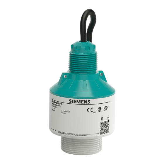
Description 3.2 Principle of operation • Software version from 1.2.0 Constituent parts Radar antenna Process fitting Electronics housing Mounting thread Connection cable Figure 3.1 Components of SITRANS LR100 Nameplate The nameplate contains the most important data for identification and use of the transmitter. -
Page 16: Adjustment
The frequency change is proportional to the distance and is converted into the level. Adjustment Wireless adjustment Devices with integrated Bluetooth module can be adjusted wirelessly via Siemens mobile IQ app. Transmitter Smart device Figure 3.3 Wireless connection to standard operating devices with integrated Bluetooth LE... -
Page 17: Accessories
Description 3.5 Accessories Transport inspection The delivery must be checked for completeness and possible transit damage immediately at receipt. Ascertained transit damage or concealed defects must be appropriately dealt with. Storage Up to the time of installation, the packages must be left closed and stored according to the orientation and storage markings on the outside. -
Page 18: Installing/Mounting
Installing/mounting General instructions Ambient conditions The transmitter is suitable for standard and extended ambient conditions acc. to DIN/ EN/IEC/ANSI/ISA/UL/CSA 61010-1. It can be used indoors as well as outdoors. Process conditions Note For safety reasons, the transmitter must only be operated within the permissible process conditions. -
Page 19: Mounting Instructions
Installing/mounting 4.3 Mounting instructions Figure 4.1 Mounting via a mounting bracket Mounting instructions Installation position When mounting the device, keep a distance of at least 200 mm (7.874 in) from the vessel wall. If the device is installed in the center of dished or round vessel tops, multiple echoes can arise. - Page 20 Installing/mounting 4.3 Mounting instructions Reference point Figure 4.3 Reference point Inflowing medium Do not mount the transmitters in or above the filling stream. Make sure that you detect the medium surface, not the inflowing product. Figure 4.4 Mounting of the radar transmitter with inflowing medium Nozzle For nozzle mounting, the nozzle should be as short as possible and its end rounded.
- Page 21 Installing/mounting 4.3 Mounting instructions Figure 4.6 Nozzle mounting with deviating nozzle dimensions Nozzle diameter d Nozzle length h 40 mm 1½" ≤ 150 mm ≤ 5.9 in 50 mm 2" ≤ 200 mm ≤ 7.9 in 80 mm 3" ≤ 300 mm ≤ 11.8 in 100 mm 4" ≤ 400 mm ≤ 15.8 in 150 mm 6" ≤ 600 mm ≤ 23.6 in Orientation In liquids, direct the device as perpendicular as possible to the medium surface to achieve optimum measurement results.
-
Page 22: Measurement Setup - Flow
Installing/mounting 4.4 Measurement setup - Flow Figure 4.8 Agitators Foam generation Through the action of filling, stirring and other processes in the vessel, foams which considerably damp the emitted signals may form on the medium surface. If foams lead to measurement errors, you should use transmitters with guided radar. Measurement setup - Flow Mounting In general, the following must be observed while mounting the device:... - Page 23 Installing/mounting 4.4 Measurement setup - Flow Predefined curves A flow measurement with these standard curves is very easy to set up, as no dimensional information of the flume is required. 1.86 • Palmer-Bowlus flume (Q = k x h • Venturi, trapezoidal weir, rectangular flume (Q = k x h •...
- Page 24 Installing/mounting 4.4 Measurement setup - Flow Rectangular overfall Overfall orifice (side view) Upstream water Tailwater Overfall orifice (view from tailwater) Figure 4.9 Flow measurement with rectangular flume: h = max. filling of the rectangular max. flume Khafagi-Venturi flume Position transmitter Venturi flume Figure 4.10 Flow measurement with Khafagi-Venturi flume: h = max.
- Page 25 Installing/mounting 4.4 Measurement setup - Flow SITRANS LR100 Operating Instructions, 10/2021, 62705-76-01...
-
Page 26: Connecting
Connecting Preparing the connection Safety instructions Always keep in mind the following safety instructions: • Carry out electrical connection by trained, qualified personnel authorised by the plant operator WARNING Only connect or disconnect in de-energized state. Voltage supply The data for power supply are specified in chapter ""Technical data". Note Power the transmitter via an energy-limited circuit (power max. -
Page 27: Wiring Plan
Connecting 5.2 Wiring plan Wiring plan Wire assignment, connection cable Figure 5.1 Wire assignment in permanently connected connection cable Wire colour Function Polarity Black Voltage supply, signal output Plus (+) White Voltage supply, signal output Minus (-) Shielding Switch-on phase After connection to the power supply, the device carries out a self-test: •... -
Page 28: Access Protection
Access protection Bluetooth radio interface Devices with a Bluetooth radio interface are protected against unwanted access from outside. This means that only authorized persons can receive measured and status values and change device settings via this interface. Bluetooth PIN A Bluetooth PIN is required to establish Bluetooth communication via the adjustment tool (smartphone/tablet/notebook). - Page 29 Access protection 6.2 Protection of the parameterization Device Access PUK The Device Access PUK allows unlocking the device in case the user PIN is no longer known. It can't be changed. The Device Access PUK can also be found on the supplied information sheet ""Device Bluetooth and Parameter Access Codes".
-
Page 30: Setup With Smart Device (Bluetooth)
Setup with smart device (Bluetooth) Connecting Connecting Start the adjustment app. The smart device searches automatically for Bluetooth- capable transmitters in the area. The devices found are listed. Select the requested transmitter in the device list. Authenticate When establishing the connection for the first time, the operating tool and the transmitter must authenticate each other. - Page 31 Setup with smart device (Bluetooth) 7.1 Connecting SITRANS LR100 Operating Instructions, 10/2021, 62705-76-01...
-
Page 32: Operating
Operating To configure the device: Download and install the SITRANS mobile IQ app from the App store to your mobile device. Launch the app. Devices in range will appear. Click on the device you wish to connect to. On first connection, a PIN code shipped with the device needs to be entered (see Device Bluetooth and SITRANS LR100 Operating Instructions, 10/2021, 62705-76-01... - Page 33 Operating Parameter Access Codes sheet). Following successful PIN entry, the device cockpit will be shown. SITRANS LR100 Operating Instructions, 10/2021, 62705-76-01...
- Page 34 Operating Use the Setup/Quick Commissioning to configure the transmitter for your application type. SITRANS LR100 Operating Instructions, 10/2021, 62705-76-01...
- Page 35 Operating SITRANS LR100 Operating Instructions, 10/2021, 62705-76-01...
- Page 36 Operating • Mode 1: EU, Albania, Andorra, Azerbaijan, Australia, Belarus, Bosnia and Herzegovina, Canada, Liechtenstein, Morocco, Moldavia, Monaco, Montenegro, New Zealand, Northern Macedonia, Norway, San Marino, Saudi Arabia, Serbia, Switzerland, Turkey, Ukraine, United Kingdom, USA • Mode 2: Japan, South Korea, Taiwan, Thailand •...
- Page 37 Operating SITRANS LR100 Operating Instructions, 10/2021, 62705-76-01...
-
Page 38: Diagnostics And Troubleshooting
Diagnostics and troubleshooting Maintenance Maintenance If the device is used properly, no special maintenance is required in normal operation. Precaution measures against buildup In some applications, buildup on the antenna system can influence the measuring result. Depending on the transmitter and application, take measures to avoid heavy soiling of the antenna system. -
Page 39: Diagnosis, Fault Messages
Diagnostics and troubleshooting 9.3 Diagnosis, fault messages • Signal processing Fault rectification The first measures are: • Evaluation of fault messages • Checking the output signal • Treatment of measurement errors A smart device (smartphone/tablet) with the adjustment app or a PC/notebook with the PDM and the suitable EDD offer you further comprehensive diagnostic possibilities. - Page 40 Diagnostics and troubleshooting 9.4 Status messages according to NE 107 more detailed error messages available under the menu item ""Diagnostics" via the respective adjustment module. Status messages The status messages are divided into the following categories: • Failure • Function check • Out of specification •...
- Page 41 Diagnostics and troubleshooting 9.4 Status messages according to NE 107 Code Cause Rectification Text message no measured value Transmitter tilted Clean the antenna system available F017 Adjustment not within specification Change adjustment according to the limit values (difference between min. Adjustment span too and max.
-
Page 42: Treatment Of Measurement Errors
Diagnostics and troubleshooting 9.5 Treatment of measurement errors Out of specification Code Cause Rectification Text message S600 Temperature of the electronics in the Check ambient temperature non-specified range Impermissible Insulate electronics electronics temperature S601 Danger of vessel overfilling Make sure that there is no further filling Overfilling Check level in the vessel... - Page 43 Diagnostics and troubleshooting 9.5 Treatment of measurement errors The images in column ""Error description" show the actual level as a dashed line and the output level as a solid line. Real level Level displayed by the transmitter Note If the output level is constant, the cause could also be the fault setting of the current output to ""Hold value".
- Page 44 Diagnostics and troubleshooting 9.5 Treatment of measurement errors Fault description Cause Rectification Create a new auto false echo suppression Adapt max. adjustment Measured value jumps The level echo cannot be In case of interferences due to towards 0 % during filling distinguished from the false signal installations in the close range: at a false signal position (jumps to Change polarisation direction...
- Page 45 Diagnostics and troubleshooting 9.5 Treatment of measurement errors Fault description Cause Rectification Remove contamination on the antenna In case of interferences due to installations in the close range: Change polarisation direction After eliminating the false signals, the auto false echo suppression must be deleted.
- Page 46 Diagnostics and troubleshooting 9.5 Treatment of measurement errors Fault description Cause Rectification transverse reflection larger than the level echo Measured value fluctuates Various echoes from an uneven Check parameter "Material Type" around 10 … 20 % medium surface, e.g. a material and adapt, if necessary cone Optimize installation position and transmitter orientation...
-
Page 47: Return Procedure
Required forms: • Delivery note • Return goods delivery note with the following information: https:// www.siemens.com/processinstrumentation/returngoodsnote • Product (item description) • Number of returned devices/replacements parts • Reason for returning the item(s) •... -
Page 48: Technical Support
[https://www.siemens.com/automation/support-request]. More information about our technical support is available at www.siemens.com/ automation/csi/service [https://www.siemens.com/automation/csi/service] Internet service and support In addition to our documentation, Siemens provides a comprehensive support solution at www.siemens.com/automation/service&support [https:// www.siemens.com/automation/service&support] Contact person If you have additional questions about the device, please contact your Siemens personal contact at www.automation.siemens.com/partner [https://... -
Page 49: How To Proceed If A Repair Is Necessary
Diagnostics and troubleshooting 9.8 How to proceed if a repair is necessary How to proceed if a repair is necessary If it is necessary to repair the transmitter, please contact Siemens. You find the locations on www.siemens.com/processautomation [https://www.siemens.com/ processautomation]. SITRANS LR100... -
Page 50: Service And Maintenance
Devices can be returned to the supplier within the EC, or to a locally approved disposal service for eco-friendly recycling. Observe the specific regulations valid in your country. Further information about devices containing batteries can be found at: (https:// support.industry.siemens.com/cs/document/109479891/) Note Special disposal required The device includes components that require special disposal. •... - Page 51 Service and maintenance 10.2 Disposal SITRANS LR100 Operating Instructions, 10/2021, 62705-76-01...
-
Page 52: Certificates And Approvals
The Bluetooth radio module in the device has been tested and approved according to the current edition of the applicable country-specific norms or standards. The confirmations as well as regulations for use can be found in the document ""Radio licenses" supplied or on www.siemens.com/level [https://www.siemens.com/ level]. 11.2 EU conformity The device fulfils the legal requirements of the applicable EU directives. - Page 53 Certificates and approvals 11.3 NAMUR recommendations SITRANS LR100 Operating Instructions, 10/2021, 62705-76-01...
-
Page 54: Technical Data And Dimensions
Technical data Note for approved transmitters Device specifications: Siemens makes every effort to ensure the accuracy of these specifications, but reserves the right to change them at any time. Device-specific approvals: The device-specific approvals are always to be found on the nameplates on the device. - Page 55 Technical data and dimensions 12.1 Technical data • Mode 3 ≥ 250 mm (9.843 in) Depending on application and medium Depending on the operating conditions Reference point Measured variable, max. measuring range Figure 12.1 Data of the input variable Switch-on phase Run-up time for U = 12 V DC, 18 V DC, 24 V DC < 15 s Starting current for run-up time...
- Page 56 Technical data and dimensions 12.1 Technical data Range of the output signal 3.8 … 20.5 mA (default setting) Signal resolution 0.3 µA Resolution, digital 1 mm (0.039 in) Fault signal, current output (adjustable) ≤ 3.6 mA, >=21 mA, last valid measured value Max. output current 22 mA Load See load resistance under Power supply Starting current ≤ 3.6 mA;...
- Page 57 Technical data and dimensions 12.1 Technical data Variables influencing measurement accuracy Specifications apply to the digital measured value Temperature drift - Digital value < 3 mm/10 K, max. 5 mm Specifications apply also to the current output Temperature drift - Current output < 0.03 %/10 K or max. 0.3 % relating to the 16.7 mA span Deviation in the current output due to digital/ < 15 µA...
- Page 58 Technical data and dimensions 12.1 Technical data Bluetooth interface Bluetooth standard Bluetooth 5.0 Frequency 2.402 … 2.480 GHz Max. emitted power +2.2 dBm Max. number of participants Effective range typ. 25 m (82 ft) Depending on the local conditions Adjustment Smart device SITRANS mobile IQ Voltage supply Operating voltage U •...
-
Page 59: Dimensions
Technical data and dimensions 12.2 Dimensions 12.2 Dimensions Figure 12.4 Dimensions SITRANS LR100 12.3 Licensing information for open source software Open source software components are also used in this device. A documentation of these components with the respective license type, the associated license texts, copyright notes and disclaimers can be found on our homepage.