FUTABA T10PX Full Manual
Digital proportional r/c systems
Hide thumbs
Also See for T10PX:
- Short manual (40 pages) ,
- Quick start manual (9 pages) ,
- Full manual (215 pages)
Table of Contents
Advertisement
Quick Links
Advertisement
Table of Contents

Related Manuals for FUTABA T10PX


Summary of Contents for FUTABA T10PX
- Page 1 WEB FULL MANUAL 1M23Z08002...
- Page 2 OUTSIDE NORTH AMERICA Please contact the Futaba importer in your region of the world to assist you with any questions, problems or service needs. Please recognize that all information in this manual, and all support availability, is based upon the systems sold in North America only. Products purchased Compliance Information Statement (for U.S.A.)
-
Page 3: Table Of Contents
● Modifying For Left-hand Use ……………… 26 ● Set Contents …………………………………… 8 ● Angle Spacer ………………………………… 28 ● Specifications …………………………………… 9 ● When Removing The Paddle Switch ……… 29 ● Transmitter T10PX Nomenclature ………… 10 ● Trigger Brake Lever Replacement ………… 30 ● Power & Display Switch …………………… 11 ● Non-telemetry LED (telemetry OFFsign) … 30 ● Display When Power Switch Is Turned On ● Handling The Antenna ……………………… 30 ●... - Page 4 Table Of Contents ● Battery ………………………………………… 55 ● A.B.S. …………………………………………… 119 ● Data And Time ……………………………… 56 ● Start …………………………………………… 124 ● LED Setting …………………………………… 57 ● Engine Cut …………………………………… 126 ● Calibration …………………………………… 58 ● Response ……………………………………… 128 ● Receiver Update ……………………………… 60 MIXING MENU ● Servo Update ………………………………… 62 ●...
-
Page 5: For Your Safety As Well As That Of Others
Under other conditions, the set will not operate, or the specified performance will not be displayed even if it operates. In addition, it may cause servo trouble. Futaba will not be responsible for problems caused by the use of other than genuine Futaba parts. Use the parts specified in the instruction manual and catalog. -
Page 6: Operation Precautions
Never insert or remove the charger while your hands are wet. You may get an electric shock. Do not use the T10PX transmitter’s battery as the receiver’s battery. Since the transmitter’s battery has an overload protection circuit, the output power will be shut down when the high current load is applied. -
Page 7: Storage And Disposal Precautions
Always use only genuine Futaba transmitters, receivers, servos, ESCs (electronic speed controls), Batter- ies and other optional accessories. Futaba will not be responsible for problems caused by the use of other than genuine Futaba parts. Use the parts specified in the in- struction manual and catalog. -
Page 8: Features
Futaba speed controller (ESC), MC960CR, MC950CR, -SR(Super response) mode MC850C, MC851C, MC602C, MC402CR, etc. variable frequency and other data changes by PC at the T10PX. improved response compared to conventional. SR servo is required to use SR mode. -Throttle speed... -
Page 9: Set Contents
Always use only genuine Futaba transmitters, receivers, servos, ESCs (electronic speed controls), batter- ies and other optional accessories. Futaba will not be responsible for problems caused by the use of other than Futaba genuine parts. Use the parts specified in the in- struction manual and catalog. -
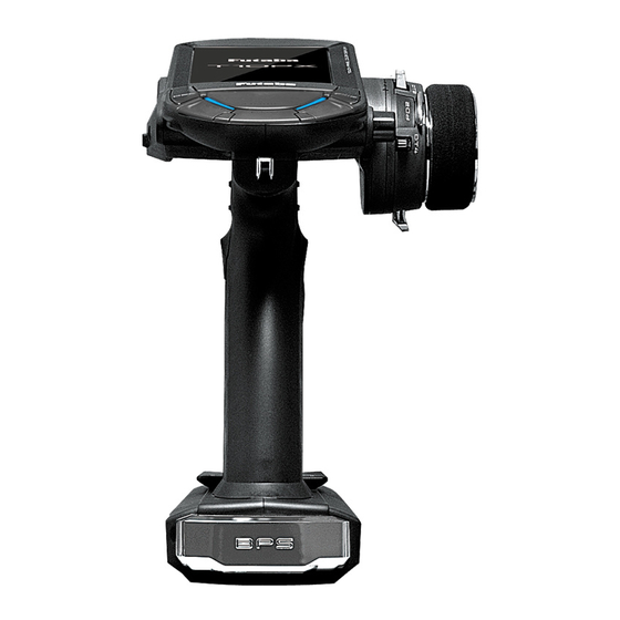
Page 10: Transmitter T10Px Nomenclature
Transmitter T10PX Nomenclature *Please be careful not to push the switch too strongly. Touch screen LCD Power switch Display switch Antenna Home button Edit button 1 ES1 Edit button 2 ES2 Digital Dial (DL1) / Push switch 5 (SW5) Edit button 3 ES3 Hook Push switch SW3 Steering wheel Grip switch SW2 Grip Handle Multiport ... -
Page 11: Power & Display Switch
Power & Display Switch The power switch and display switch are push switches. When the power switch (PWR) is held down, operation starts by transmitting radio waves. When the display switch (DSP) is held down, the transmitter side data can be checked and set. Power &... -
Page 12: Power Off Forgotten Alarm & Auto Power Off
Power Off Forgotten Alarm & Auto Power Off At T10PX initialization, if steering wheel, throttle trigger, push switch, edit button, or other operation is not performed within 10 minutes, an audible alarm will sound and the message " " will appear. -
Page 13: Digital Trim Operation
This prevents the linkages from binding when adjustments are made. microSD port And USB port microSD port Rotating the antenna 90 ° reveals T10PX model data and telemetry log data can be two ports. saved by using a commercial microSD card. When T10PX software updates are released, the microSD card can also be used to make the update. -
Page 14: Trim/Dial Lock
Trim/Dial Lock T10PX setup and operation by digital trim DT1, DT2, DT3, DT4, DT5 and DT6 and dials DL1 can be prohibited. Setting When the HOME button is pressed for about 1 second at the initial screen, a confirma- tion beep is generated and the trim/dial lock display mark appears on the screen. -
Page 15: Wheel & Trigger Tension Adjustment
Wheel & Trigger Tension Adjustment Adjustment Using hex wrench, adjust the wheel spring tension by turning the screw in- side the adjusting hole. - The spring is set to the weakest ten- sion at the factory. - When the adjusting screw is turned clockwise, the spring tension increas- Wheel tension Trigger tension ad-... -
Page 16: Removal Of Trigger Unit
Removal Of Trigger Unit The trigger can be removed to replace the trigger spring. How to remove M2×8 Remove the fixing screw shown in the figure with a hex wrench. Be careful not to lose the screws. Note: M2×8 Be careful not to damage the case or M2×8 to remove. -
Page 17: Sw: Push Switch Pd: Paddle Switch Dl: Dial
SW: Push switch PD: Paddle switch DL: Dial SSW: Slide switch The position of various switches. The assignment of each function can be changed for T10PX. SW5/DL1 SSW1 BPS: SW4 Grip Rubber Trigger Guard It is possible to make the narrow... -
Page 18: Battery Replacement Method
There is the dan- ger of collision if the power is cut while running (cruising). The use of Futaba genuine NiMH/LiFe or LiPo batteries is strongly recommended. -
Page 19: When Using Optional Battery
When Using The Optional Battery When using an optional rechargeable battery, replace the battery as described below. -Always use the optional FT2F1100B, FT2F1700B, FT2F2100B, HT5F1800 or LT- 2F2000B rechargeable battery. *Products for Europe cannot use NiMH / LiFe batteries. -The type of power source used must be selected through the system setting. -When the transmitter will not be used for a long time, remove the battery. -
Page 20: When Charging For The Optional Nimh/Life Battery
Remove the battery cover. instead of fully charged. Also be careful that the battery does not enter the over discharged state Disconnect the battery from the T10PX. due to self-discharge. Periodically (about every 3 months) charge the battery. In addition, always re-... -
Page 21: Lipo Battery Lt2F2000B Replacement Method
When Charging For The Optional LiPo Battery To charge the battery, connect a type C USB cable to the Futaba optional USB AC adapter or a commercially available USB AC adapter (USB-A type 5 V-2 A) from the Lipo dedicated charging port. -
Page 22: Steering Wheel Arrangement
Steering Wheel Arrangement ● Changing the wheel position ● Modifying for left-hand use The wheel section left and right in- using the accessory APA wheel posi- stallation direction can be reversed. 5° ● Angle spacer The wheel mounting angle can be changed by using the optional angle spacer 5°. -
Page 23: Exchange Procedure To Wheel Adaptor 32 Deg And Large Diameter Wheel
Exchange procedure to wheel adaptor 32 deg and large diameter wheel - Obtain hex wrench./ Remove the battery. Hold the wheel and remove the screw. (Using a hex wrench.) Pull off the wheel and wheel adapter. Steering wheel mounting screw Install the standard or large diameter steering wheel and the 32 degree wheel adapter using the screw. -
Page 24: Installing The Accessory Apa Steering Wheel Offset Adapter
Installing the accessory APA steering wheel offset adapter - Obtain hex wrench./ Remove the battery. Remove the 2 steering unit mounting screws (M3x12 screw). M3×12 (Using a hex wrench.) Remove the 2 mounting screws com- M3×12 pletely from the transmitter body. Gently remove the steering unit, without pulling excessively on the wiring. - Page 25 Fit the rear cover and attach the APA to M2×10 the steering housing with three M2x10 screws and one M2x6 screw. M2×10 APA uses the inside holes. The mounting angle in the direction of rotation can be adjusted. M2×10 M2×6 Normal screw position...
-
Page 26: Modifying For Left-Hand Use
Modifying for left-hand use Remove the 2 steering unit mounting screws (M3x12 screw). (Using a hex wrench.) M3×12 Remove the 2 mounting screws com- pletely from the transmitter body. M3×12 Gently remove the steering unit, without pulling excessively on the wiring. - Remove the steering unit slowly so that the internal wiring is not pulled unrea- sonably. - Page 27 Replace the steering unit bottom cover. • Slide it outward and pull it out. Steering unit bottom cover Install the rear unit to the connector on the opposite side of the transmitter body. • Install slowly so that the wiring is not pinched. Rear unit Rear unit fixing screw Fit the rear unit to the t r a n s m i t t e r b o d y...
-
Page 28: Angle Spacer
Angle Spacer The wheel mounting angle can be changed by using the optional angle spacer 5°. - The angle spacer use the included four M2x5 mm hex screws. - Obtain hex wrench. / Remove the battery. - The length of the screws used at each part differs. When reassembling the steering wheel unit, always use the specified screws. -
Page 29: When Removing The Paddle Switch
When Removing The Paddle Switch If the paddle switch interferes with operation, you can remove the paddle switch in the following ways. Remove the wheel unit from the trans- mitter according to "Installing the acces- sory APA steering wheel offset adapter". Wheel unit M2.6×8 Use a Phillips screwdriver to remove the... -
Page 30: Trigger Brake Lever Replacement
Trigger Brake Lever Replacement The trigger brake lever can be replaced with the optional trigger brake lever for 7PXR / 7PX / 4PM. *When the brake lever is changed, perform throttle side correction by adjuster function. Brake lever replacement Hold the trigger, remove the brake lever mount- ing screw using the hex wrench, and remove the brake lever. -
Page 31: Receiver Terminology
Under other conditions, the set will not operate, or the specified performance will not be displayed even if it operates. In addi- tion, it may cause trouble with servos and other equipment. Futaba will not be responsible for damage, etc. caused by combi- nation with the products of other companies. -
Page 32: Receiver And Servo Connections
Installation Receiver And Servo Connections Connect the receiver and servos as shown below. Connect and install the receiver and servos in accordance with " Installation Safety Precautions " on the next page. troller to the motor and battery depends on the motor controller used. Purchase the motor controller and servos separately. -
Page 33: Installation Safety Precautions
Installation Safety Precautions Warning Receiver (receiver antenna) Do not cut or bundle the receiver antenna wire.(R404SBS) Do not bundle the receiver antenna wire together with the motor controller lead wire.(R404SBS) Keep the receiver antenna at least 1 cm away from motor, battery, and other wiring carrying heavy current. Do not use a metal receiver antenna holder on a plate made of metal, carbon, or other conductive mate- rial. - Page 34 Screw Damper Eyelet Mechanical plate (or) Nut (as required) When installing the servo, always install the accessory grommet and grommet are not installed correctly. Warning Servo Throw Operate each servo over its full stroke and be sure the linkage does not bind or come loose. The continuous application of unreasonable force to a servo may cause damage and excessive battery drain.
-
Page 35: Linking Method For F-4G System
FHSS", "Mini-Z"or "S-FHSS" is displayed. If not displayed, there is probably an abnormality or trouble so contact a Futaba Service Center. When a screen is displayed at the "DSP" side, "Display" is displayed. *Since the R404SBS(E) receiver supplied with the T10PX set uses the F-4G system, T10PX receiver setup must be set to F-4G. - Page 36 In "Receiver", select and tap the system to be set from systems. The confirmation screen will be displayed. To execute, tap [Yes] to hear an electronic sound and finish setting. To cancel, select [No] and touch it. If you change the system, be sure to link it with the receiver and turn the power on again.
- Page 37 Bring the transmitter and receiver within 50 cm of each other (antennas do not touch) and turn on the receiver power. Touch [Link] on the transmitter T10PX screen, you will hear a chime sound and T10PX will enter the link mode for 20 seconds.
-
Page 38: S-Fhss/Fasst Receiver Link
Precaution: If there are many Futaba 2.4GHz systems turned on close to your receiver might not link to your transmitter. In this case, even if the receiver’s LED stays solid green, unfortunately, the receiver might have established a link to one of the other transmitters. -
Page 39: Kyosho Mini-Z Evo Dedicated Receiver
Bring the transmitter and the receiver close to each other, within 20-inches (half a meter). Turn on the Mini-Z receiver RA-42. Touch [Link] on the transmitter T10PX screen, you will hear a chime sound, and T10PX will enter the link mode for 20-sec- onds. -
Page 40: Throttle Ratio Check
-The throttle servo travel can be set to 50:50, 60:40, 70:30, or 100:0 for throttle trig- ger operation as required by the Throttle mode (in the Linkage menu). -The throttle brake operation might be close by setting it to " 100:0 " when the T10PX transmitter with the boat is used. -
Page 41: Menu Selection
Menu Selection Use the HOME button and the LCD screen touch panel to operate the screen. In this operation manual, the HOME button is indicated by the following symbols. Display Menu Screen Push the HOME button Press and hold the or tap the touch panel. -
Page 42: Home/Es1/Es2/Es3 Button Setting
Home/ES1/ES2/ES3 Button Setting When you push the HOME button from the home screen, it moves to the Model se- lect screen at the factory shipping the HOME button. Pushing the HOME button on the menu screen or each setting screen will return you to the previous screen. Press and hold the HOME button on the menu screen or each setting screen to return to the Home screen. -
Page 43: Value Of Each Function And Changing The Set Value
Value Of Each Function And Changing The Set Value On the setting screen of each function, if you tap the item to be set, [-] [reset] [+] will be displayed at the bottom of the screen, tap the [-] [+] on the panel Set. Tap[Reset] to return to the initial value. -
Page 44: User Menu
User Menu The T10PX allows you to register your favorite functions in the user menu. You can copied by model copy. (8 types on a page, up to 48 varieties on 6 pages) Displaying And Editing The User Menu Screen On the user menu screen, you can view the user menu screen by tapping [User Menu] on the home screen. - Page 45 Date and time setting/Displaying the time on the home screen or selecting the total timer Date and time LED setting The steering wheel and throttle trigger correction Calibration Update the receiver (R404SBS/R404SBS-E/R334SBS/R334SBS-E) using the T10PX Receiver update Update the servo using the T10PX Servo update Model memory call...
- Page 46 Twin servo mixing of the steering Steering mixing Front and rear independent brake control for 1/5GP car, etc. Brake mixing The sensitivity of Futaba car rate gyros can be adjusted Gyro mixing 4-wheel steering mixing 4WS mixing Front and rear ESCs mixing Dual ESC The CPS-1 of Futaba LED controller can be adjusted.
-
Page 47: Handling A Microsd Card (Commercial Product)
" Save screen " is set at the push switch by switch select, an image of the screen to be displayed on the T10PX is saved by that switch. The saved im- age is stored in a folder called " PICTURE " . Save the images used in the " Home Screen "... -
Page 48: Function Map
Function Function Map HOME MENU System menu 1 Model menu Linkage menu 1 Racing menu Mixing menu 1 Telemetry menu Accessory menu 1 System menu 2 Linkage menu 2 Mixing menu 2 Accessory menu 2 System menu Date and Receiver Servo Display... - Page 49 Throttle mode Channel (Trigger) reverse Receiver Servo view Sub trim End point Fail-safe Acceleration Linkage menu Trim / Dial Switch Channel Channel Condition Idle up D/R, ATL select select limiter setting Racing menu Traction Curve ( EXP) Speed A.B.S. Start Engine cut Response control...
-
Page 50: System Menu
SYSTEM MENU Display This function is Backlight brightness, dimming time, etc. setting and touch panel cor- rection menu. There is also a touch panel sensitivity adjustment. System menu screen Display Home screen Menu screen Menu-1 Menu-2 Display setup (Backlight decrease brightness adjustment) Tap the value button of the [Backlight max, brightness] or [Backlight min, brightness]. - Page 51 "ON": Function ON Setting (Setting of start/end screen) - Tap (ON)/(OFF). This turns the “Futaba T10PX” show or not show when pow- ering the transmitter on or off. Tap on the "Opening demo" (ON ) or ( OFF) and select ON/ OFF.
-
Page 52: Information
SYSTEM MENU Information With this system information, you can select user name setting, display language, use unit of telemetry information. It also displays the software version. System menu screen Information Home screen Menu screen Menu-1 Menu-2 Deletion and cancellation of Move cursor characters (Undo) Tap to select characters Selection of alphabet/number/"kana"... - Page 53 SYSTEM MENU Language select Language setting Tap to select from the list (Language select) Tap [Language], a list of languages will be displayed on the screen. If you tap the language you want to use from the list, the language display will be changed and you will be taken to the home screen.
-
Page 54: Sounds
SYSTEM MENU Sound This function can set the volume of " Operation " , " Warning ", and " Telemetry speech info " . -The volume of when switch, dial, home button, and trim are operated can be adjusted. -The volume of the audible alarm sound can be adjusted. -When the telemetry function is used, the volume of the voice that announces the tem- System menu screen Sound... -
Page 55: Battery
Therefore, always set the battery type to match the power supply being used. When using a Futaba rechargeable type battery, always select “ LiFe 2 cells ” “ LiPo 2 cells ” or “ NiMH 5 cells ” . The incorrect setting will substantially shorten the time from low battery alarm to system stopping and is very dangerous. -
Page 56: Data And Time
SYSTEM MENU Data And Time This function adjusts the system clock of the T10PX transmitter. Perform this setting when you purchase the set, and when adjustment is necessary. Whether the time or the total time (accumulation timer) is displayed on the initial screen can be set. -
Page 57: Led Setting
SYSTEM MENU LED Setting You can adjust the brightness and lighting method of the pilot LED light. The pilot LED lighting method can be selected from " Always On " , " " or " Backlight " . System menu screen LED setting Home screen Menu screen... -
Page 58: Calibration
HOME button. If the op- eration cannot usually be ended even when correction is re- peated, please contact the Futaba Service Center. When finished, return to the System menu screen by pressing the HOME button. - Page 59 HOME button. When operation cannot usually be ended even when correction is repeated, and cannot be ended usually, contact the Futaba Service Center. When finished, return to the System menu screen by pressing the HOME button. Return to table of contents...
-
Page 60: Receiver Update
Cover Receiver battery (The receiver power supply can be con- nected to the each of CH1-4.) Turn on the DSP or PWR switch of T10PX and display the receiver update screen. System menu screen Receiver update Home screen Menu screen... - Page 61 T10PX. - Do not turn off the power of T10PX while updating. When the update is completed, a message is displayed on the screen, and the LED of the receiver stays flashing green.
-
Page 62: Servo Update
Communication port 2 way hub Receiver Cover battery HV servo Non HV servo Turn on the DSP or PWR switch of T10PX and display the receiver update screen. System menu screen Servo update Home screen Menu screen Menu-1 Menu-2 Connect the servo to the T10PX and tap [Update] to update. -
Page 63: Model Menu
MODEL MENU Model Select Forty model data (model data for 40 R/C cars) can be saved in the T10PX transmit- ter and used when the relevant model data selected. However, models copied in the microSD card cannot be used by directly calling from the card. Please copy it to the T10PX main unit when using it. -
Page 64: Model Copy
MODEL MENU Model Copy The contents of model memory can copy to another model memory. You can also save content to a microSD card for backup or to copy to another T10PX. Model copy Home screen Menu screen Model menu screen... - Page 65 When finished, return to the Model menu screen by pressing the HOME button. The microSD card storage destination When a microSD card is installed in the T10PX, a folder called "Futaba" is created, and folders called "LOG" and "MODEL" are created in it. The "MODEL" folder contains the model data.
-
Page 66: Model Name
MODEL MENU Model Name This function allows you to assign a name up to ten characters, to each model memory. Model name Home screen Menu screen Model menu screen Deletion and cancellation of Move cursor characters (Undo) Tap to select characters Selection of alphabet/number/"kana"... -
Page 67: Model Delete (Model Saved On Microsd Card)
Model Delete (Model saved on microSD card) This function deletes model data saved on the microSD card. Model deletion is displayed on the menu only when the microSD card is set in the T10PX card slot. Model delete Home screen... -
Page 68: Data Reset
MODEL MENU Data Reset This function resets the contents of the currently called model memory. The reset method can be selected from among the four types described below. These resets do not initialize the calibration function and system function. -Model data This mode is Initializes only the function setting data. -
Page 69: Model Type
MODEL MENU Model Type It can be changed to the initial setting suitable for 1/5 big car and drift car. Also, the so it is easy to set each type of machine. -Changing the model type will initialize the current model data. -It is recommended to change before setting each function. -
Page 70: Linkage Menu
LINKAGE MENU Receiver This menu selects the settings matched to the receiver system used and the type of ser- vo and the items selected at the T10PX, linking of the T10PX with the T-FHSS telem- etry system, and ON/OFF. HOME... - Page 71 Bring the transmitter and receiver within 50 cm of each other (antennas do not touch) and turn on the receiver power. Touch [Link] on the transmitter T10PX screen, you will hear a chime sound and T10PX will enter the link mode for 20 seconds.
- Page 72 This ends reading of mutual ID and displays the memorized receiver ID number on the T10PX screen. Power cycle the receiver. If the "Receiver not found" error screen is displayed, linking failed. Check the set contents and repeat the linking operation.
- Page 73 Precaution: If there are many Futaba 2.4GHz systems turned on close to your receiver might not link to your transmitter. In this case, even if the receiver’s LED stays solid green, unfortunately, the receiver might have established a link to one of the other transmitters.
-
Page 74: Servo View
LINKAGE MENU Servo View The servo operation of each channel can be checked. Process of the steering angle ad- Linkage menu screen Servo view Home screen Menu screen Menu-1 Menu-2 The number of channels varies depending on the selected system. Confirm operation Operating each channel, such as a steering wheel or throttle trigger, the graph moves, and the servo operation can be confirmed. -
Page 75: Throttle Mode (Trigger)
However, when using the MC950CR, MC851C, MC602C, MC402CR, or other Futaba ESC, confirm that the ESC is in the neutral position and the set is in the operation mode before setting the neutral brake function switch to ON. - Page 76 OFF. Warning display Reference The ESC neutral brake function and the T10PX neutral brake function can be used that only one neutral brake function be used. Trim/Dial Setting When the neutral brake function is , the neutral brake rate adjustment is auto- "...
-
Page 77: Channel Reverse
LINKAGE MENU Channel Reverse This function reverses the direction of operation of the servos related to transmitter steering, throttle, channel 3-10 channels operation. However, when the position set by trim or sub trim shifts from the center, the center becomes the opposite side. Linkage menu screen Channel reverse Home screen... -
Page 78: Sub Trim
LINKAGE MENU Sub Trim Use this function to adjust the neutral position of the steering, throttle, channel 3, chan- Linkage menu screen Sub trim Home screen Menu screen Menu-1 Menu-2 Tap to change page. The number of channels varies depending on the *Sub trim adjusts the entire range of the selected system. -
Page 79: End Point
LINKAGE MENU End Point Used to adjust the left and right end points of the steering wheel, adjust the throttle high nel servo upside/downside manipulated variable. Maximum steering angle The functions shown below may have been adjusted, or the operating range set by functions are adjusted. - Page 80 LINKAGE MENU Linkage menu Linkage menu screen End point Home screen Menu screen Menu-1 Menu-2 Tap to change page Steering end point adjustment (Preparation) - Before setup of the steering end point adjustment, set the steer- ing D/R dial (initial setup: DT5) to the maximum steering angle position 100%.
- Page 81 LINKAGE MENU Throttle end point adjustment (Preparation) Adjustment buttons - Use the [+] and [-] buttons to - Before setting the throttle end point adjustment, set the throttle make adjustments. ATL dial (initial setup: DT6) to the maximum throttle angle po- - Return to the initial value by tapping the [reset] buttons.
-
Page 82: Fail-Safe/Battery Fail-Safe
LINKAGE MENU Fail-safe/Battery Fail-safe This function sets the servo operation position when transmitter signals cannot be re- ceived by the receiver for some reason, or the battery voltage has dropped. -Fail-safe mode This function moves each servo to a preset position when the receiver cannot receive the signals from the transmitter for some reason. - Page 83 LINKAGE MENU Fail-safe mode selection (Preparation) - Tap the fail-safe part of the channel you want to set. The mode list appears on the Fail-safe menu screen. (Mode selection) Tap from the list and select the mode. To cancel, tap [Cancel]. Fail-safe mode Off, Hold, Fail-safe (Each channel can be individually set.)
-
Page 84: Acceleration
LINKAGE MENU Acceleration nential, which adjusts the whole throttle movement into a curve, throttle acceleration " jumps " away from neutral and then leaves the remaining response linear. Operation - Operation near the throt- 100% tle trigger neutral position becomes a sharp rise. 100% - The forward and brake sides can be set separately. - Page 85 LINKAGE MENU Throttle acceleration adjustment Adjustment buttons (Preparation) Adjust with the [+] and [-] but- tons. - Tap the value button of the [Forward]. Value input buttons appear - Return to the initial value by on the screen and make the following adjust- tapping the [reset] buttons.
-
Page 86: Trim/Dial Select
LINKAGE MENU Trim/Dial Select This function allows the selection of the function performed by the digital dial DL1 and digital trimmers (DT1 to DT6), step amount adjustment, and operating direction reversal. trim. The assigned function is also displayed on the opening screen together with the current adjustment value. - Page 87 LINKAGE MENU (Changing the operation step amount) Setting direction Tap the travel button of the [step]. Value - Tap [Nor.]/[Rev.]. (Nor.) Normal/(Rev.) Reverse input buttons appear on the screen and use the [+] and [-] buttons to adjust the step amount. Adjust button Adjust with the [+] and [-] but- tons.
- Page 88 LINKAGE MENU Set table functions (DL1/DT1, DT2, DT3, DT4, DT5, DT6) Name Function Steering trim Steering trim Throttle trim Throttle trim Channel 3 to 10 control Channel 3 to 10 control Flap Tilt mixing: flap rate Dual rate Dual rate function Sub trim Ch.1 to 10 Sub trim Ch.1~10 Acceleration (forward)
-
Page 89: Switch Select
LINKAGE MENU Switch Select This function allows the selection of the function to be performed by the switches (SW1-SW7, PD1, PD2, SSW1, steering wheel, throttle trigger) and setting of the direc- tion, etc. of operation. - The push switch SW5 is integrated with the DL1. - All switches can be made alternating operations (ON/OFF changes each time SW pressed). - Page 90 LINKAGE MENU Setting direction (Changing the operation direction) - Tap [Nor.]/[Rev.]. Tap [Nor.] or [Rev.] to set the direction. (Nor.) Normal/(Rev.) Reverse (Changing the type of operation) Setting type - Tap [Nor.]/[Alt.]. Tap [Nor.] or [Alt.] to set the type. (Nor.) Normal/(Alt.) Alternate (Steering/trigger switch setting) This is a function that uses the steering wheel and the throt-...
- Page 91 LINKAGE MENU Set table functions Push switch :SW1-SW7 Slide switch :SSW1 Paddle switch :PD1 PD2 Steering switch :SS Trigger switch :TS Abbreviation used on Function name, etc the setup screen Operation of channel 3 to 7 (Channel 5 to 7 is for S- Channel 3 to 7 control FHSS analog system only.) SSW1...
-
Page 92: Condition
LINKAGE MENU Condition ample, there are two types of data: Steering D/R is set to 90% in the normal state, and Steering D/R is set to 80% in the second state. This " Condition " can be set for each model. - Page 93 LINKAGE MENU Tap the [Condition] button to change the number of available conditions. A list of condition numbers is displayed in the "Condition name" group box. Up to 4 condi- tions can be used. Condition name This function allows you to assign a fifteen character name to each condition. From the "Condition Name"...
- Page 94 LINKAGE MENU Tap the [Copy], The confirmation message "Are you sure" appears. To execute the copy, tap [Yes] and to cancel copy, select [No]. When the copy destination condition name becomes the same name as the copy source, copying is complete. Condition change switch setting This function sets the switch to change the condition.
- Page 95 LINKAGE MENU Condition change trim/dial setting This function can change the condition by trim or dial. By operating Trim or Dial, you can change the condition as Condition 1 4 or 4 Tap the [Trim/Dial select] button to display the "Trim/Dial select" screen. (The "Trim/Dial se- lect"...
-
Page 96: Idle-Up
Futaba electronic motor speed controller (ESC) will not enter the operation mode if MC402CR, or other Futaba ESC, verify that the ESC is in the neutral position and the set is in the operation mode before setting the idle up function switch to ON. - Page 97 LINKAGE MENU Idle-up function adjustment (Preparation) - Use the switch setting function to the "Switch select". (Linkage menu) When the switch is not set, "A switch is not assigned" is displayed. Tap [Switch select] to display the switch selection screen and set the switch.
-
Page 98: D/R, Atl
LINKAGE MENU D/R, ATL D/R (Steering dual rate) The steering left and right servo travels are adjusted simultaneously. This setting is linked to transmitter grip trim DT5. When DT5 is assigned another function, the dual rate can be adjusted with this screen. ATL (Brake 1 rate) value when the braking force is weak. - Page 99 LINKAGE MENU Brake rate (ATL) adjustment Tap the travel button of the [Brake rate Adjust button Adjust with the [+] and [-] but- (ATL)]. Value input buttons appear on the tons. screen and use the [+] and [-] buttons to - Return to the initial value by tapping the [reset] buttons.
-
Page 100: Channel Limiter
LINKAGE MENU Channel Limiter Linkage menu screen Channel limiter Home screen Menu screen Menu-1 Menu-2 Tap to change page. Tap to change page. Tap to change page. The number of chan- nels varies depending on the selected sys- tem. Channel limiter adjustment (Preparation) - Tap the travel button of the channel you want to set. -
Page 101: Channel Setting
LINKAGE MENU Channel Setting This function assigns steering or throttle to any channel. You can operate steering and throttle on other channels, and operate other channels in the same way as steering and throttle. Linkage menu screen Channel limiter Home screen Menu screen Menu-1 Menu-2... -
Page 102: Racing Menu
RACING MENU Curve (EXP) Steering curve This function is used to change the sensitivity of the steering servo around the neutral " Fine-tune " function is which can adjust the rate for left and right separately. Steering Curve Home screen Menu screen Racing menu screen Curve(EXP) screen... - Page 103 RACING MENU Trim/Dial Setting The steering EXP, VTR, Curve adjustment can be controlled with digital trim DT1 to DT6 or digital dial DL1 etc. with the trim/dial select function. (Linkage menu) EXP adjustment (Preparation) Adjustment buttons - Adjust with the [+] and [-] but- -Tap the curve type and select [EXP].
- Page 104 RACING MENU Carve adjustment Add points - Select point with the [ ◀ ] or [ ▶ (Preparation) buttons. -Tap the curve type and select [Curve]. [Curve rate adjustment ] Tap [ ◀◀ ] [ ▶▶ ] to move the cursor line over the point.
- Page 105 RACING MENU Throttle curve (Forward side) This function makes the throttle high side direction servo operation quicker or milder. The selection from among three kinds of curves (EXP/VTR/Curve) is also possible. Advice When the course conditions are good and the surface has good grip, set each curve to the plus [+] side (quick side).
- Page 106 RACING MENU Adjustment method for EXP curve (Preparation) Adjustment buttons -Tap the curve type and select [EXP]. - Adjust with the [+] and [-] but- tons. - Return to the initial value by Tap the value button of the [EXP rate]. Value tapping the [reset] buttons.
- Page 107 RACING MENU Adjustment method for Curve Add points - Select point with the [ ◀ ] or [ ▶ (Preparation) buttons. -Tap the curve type and select [Curve]. [Curve rate adjustment ] Tap [ ◀◀ ] [ ▶▶ ] to move the cursor line over the point. Tap the rate setting value to adjust the curve rate of each point.
- Page 108 RACING MENU Brake curve This function makes the servo operation on the brake side faster or gentler. It does not (EXP/VTR/Curve) is also possible. If the Ratio is set to 100:0 with the trigger func- method of each curve is the same as the throttle (forward) side curve, please read previ- ous page “Throttle curve”.
-
Page 109: Speed
RACING MENU Speed Steering speed Quick steering operation will cause momentary understeering, loss of speed, or spin- ning. This function is useful in such cases. Understeering Spin Smooth cornering Without "Steering speed function" With "Steering speed function" Operation of the steering servo. (Delay function) - The steering speed when the steering wheel is operated (Turn direction) and returned (Return direction) can be inde-... - Page 110 RACING MENU Adjustment buttons Steering Speed adjustment - Adjust with the [+] and [-] but- tons. ("Turn" direction delay adjustment) - Return to the initial value by Tap the value button of the [Turn]. Value input buttons appear tapping the [reset] buttons. on the screen.
- Page 111 RACING MENU Throttle speed Sudden throttle trigger operation on a slippery road only causes the wheels to spin, and the vehicle cannot accelerate smoothly. Setting the throttle speed function reduces waste- ful battery consumption while at the same time permitting smooth, enjoyable operation. Without "Throttle speed function"...
- Page 112 RACING MENU Adjustment buttons Adjustment method for 1 Speed mode - Adjust with the [+] and [-] but- (Preparation) tons. - Return to the initial value by -Tap the speed mode and select [1]. tapping the [reset] buttons. ("ALL" turn direction delay adjustment) Speed range 1~100 Tap the [Turn] side of the [All] value button.
- Page 113 RACING MENU Adjustment buttons ("Low" and "High" return direction delay adjustment) - Adjust with the [+] and [-] but- tons. Tap the [Return] side of [Low] or [High] - Return to the initial value by value button. A warning is displayed say- tapping the [reset] buttons.
- Page 114 RACING MENU ("Low", Middle", and "High" return direction delay adjustment) Adjustment buttons - Adjust with the [+] and [-] but- Tap the [Return] side of [Low], [Middle] tons. or [High] value button. A warning is dis- - Return to the initial value by tapping the [reset] buttons.
-
Page 115: Traction Control
RACING MENU Traction Control Trigger operation with cornering on a slippery road surface is hard to get traction, and smooth cornering cannot be done. By intermittently operating the operation of the throttle, you can smoothly navigate and travel on topological lines. Also, with a drift car, by intermittently operating the motor in the high point direction, a pseudo revving engine sound can be reproduced. - Page 116 RACING MENU - Delay Set the delay from when the throttle is operated until when the traction control opera- tion starts. When set to 0%, the traction control function works without delay. At 50%, control function works about 1.0-seconds later at 100%. - Cycle speed The lower this setting, the faster the pulse speed.
- Page 117 RACING MENU Adjustment buttons ("Delay" amount setup) - Adjust with the [+] and [-] but- tons. Tap the value button of the [Delay]. Value in- - Return to the initial value by put buttons appear on the screen. Use the [+] tapping the [reset] buttons.
- Page 118 RACING MENU Adjustment buttons ("Trigger point" setup) - Adjust with the [+] and [-] but- Tap the value button of the [Trigger point]. Value input buttons tons. appear on the screen. Use the [+] and [-] buttons to adjust - Return to the initial value by tapping the [reset] buttons.
-
Page 119: 119
RACING MENU A.B.S. When the brakes are applied while cornering with a 4-Wheel Drive or other types of vehicles, understeer may occur. The tendency to understeer can be eliminated and corners can be smoothly cleared by using this function. Operation - When the brakes are applied, the throttle servo will pulse in- Without "A.B.S."... - Page 120 RACING MENU - Delay Sets the delay from brake operation to ABS operation. When set to 0%, the ABS func- tion is activated without any delay. At 50%, the ABS function is activated after a delay - Cycle speed The lower this setting, the faster the pulse speed. Set value, the quicker the pulse speed. - Duty ratio Sets the proportion of the time the brakes are applied, and the time the brakes are re- leased by pulse operation.
- Page 121 RACING MENU Adjustment buttons ("Delay" amount setup) - Adjust with the [+] and [-] but- tons. Tap the value button of the [Delay]. Value in- - Return to the initial value by put buttons appear on the screen. Use the [+] tapping the [reset] buttons.
- Page 122 RACING MENU Adjustment buttons ("Trigger point" setup) - Adjust with the [+] and [-] but- tons. Tap the value button of the [Trigger point]. Value input buttons - Return to the initial value by appear on the screen. Use the [+] and [-] buttons to adjust tapping the [reset] buttons.
- Page 123 RACING MENU Switch setting Use switch the A.B.S. function ON/OFF. See the switch select function. (Linkage menu) Trim/Dial Setting The brake return amount, delay amount, and cycle speed can be controlled with digital trim DT1 to DT6 or digital dial DL1, etc. with the trim/dial select function. (Linkage menu) Example of A.B.S.
-
Page 124: Start
RACING MENU Start If the track is slippery and you begin to accelerate by pushing the trigger to full throt- tle, the car wheels will spin, and the car will not accelerate smoothly. When the Start function is activated, merely operating the throttle trigger slowly causes the throttle servo to automatically switch from the set throttle position to a preset point so that the tires do not lose their grip and the car accelerates smoothly. - Page 125 RACING MENU Adjustment buttons ("Trigger point" setup) - Adjust with the [+] and [-] but- Tap the value button of the [Trigger point]. tons. - Return to the initial value by Value input buttons appear on the screen. tapping the [reset] buttons. Use the [+] and [-] buttons to adjust the op- eration point.
-
Page 126: Engine Cut
RACING MENU Engine Cut When the switch is pressed, the throttle servo will move to the preset position without regard to the throttle trigger position. This function is convenient when used to cut the engine of boats, etc. (The switch select function in Linkage menu) Menu screen Racing menu screen Engine cut... - Page 127 RACING MENU (Preset position setup) *Shows the ON/OFF state Tap the value button of the [Preset]. Value Adjust button input buttons appear on the screen. Use the Adjust with the [+] and [-] but- [+] and [-] buttons to set the preset position tons.
-
Page 128: Response
RACING MENU Response It is a function to make the response mild. Use when the servo response is too sensitive. Home screen Menu screen Racing menu screen Response Response function adjustment (Function ON/OFF) Tap "Mode" (ON) or (OFF) to select ON/OFF. Setting "OFF": Response function OFF (Response Fastest) - Tap (ON)/(OFF). -
Page 129: Mixing Menu
MIXING MENU Steering Mixing Left and right steering can be set independently, so smooth cornering is possible. By us- ing the " " function, the motions of the servos on the left and right sides of the steering can be adjusted at the same time. The right side steering servo or the left side steering servo connects to receiver channel 1, and the other side connects to adjusted by the Ackerman rate. - Page 130 You can check the mixing used on the channel setting screen (Linkage menu). - T10PX can also be used for steering 2 by setting the throttle to other auxiliary channels setting function and mak- ing the Ch.2 assignable channel (Linkage menu).
- Page 131 MIXING MENU (Steering mixing rate adjustment) Adjustment buttons Tap the value button of the "Steering mixing - Adjust with the [+] and [-] but- rate" [Left] or [Right]. Value input buttons tons. - Return to the initial value by appear on the screen, adjust each of the tapping the [reset] buttons.
-
Page 132: Brake Mixing
MIXING MENU Brake Mixing This function is used when the front and rear brakes must be adjusted independently channel servos, or controls the 2nd channel by the independent throttle and controls the iary channels brake rate in proportion to steering operation is possible. Operation -Brake 2 and brake 3 amount, brake 1,2,3 delay, and Brake 2 and brake 3 EXP and ABS can be set. - Page 133 MIXING MENU Mixing menu Brake mixing Menu screen Home screen Menu-1 Menu-2 Brake mixing ON Brake mixing Brake mixing Brake mixing Brake 2 "ON" Brake 3 "ON" Brake 2&3 "ON" Steering mixing adjustment Setting (Function ON/OFF) - Tap (ON)/(OFF). Tap "Mixing" (ON) or (OFF) to select ON/ OFF.
- Page 134 You can check the mixing used on the channel setting screen (Linkage menu). - T10PX can also be used for brake 2 or 3 by setting the steering to other auxiliary channels with the channel set- ting function and making the Ch.1 assignable channel (Linkage menu).
- Page 135 MIXING MENU (Steering mixing) Use this function when you want to soften the brakes when the steering is operated. Adjustment buttons - Adjust with the [+] and [-] but- Tap the value button of the "Brake 1 or 2,3" tons. - Return to the initial value by [Left].
-
Page 136: Gyro Mixing
MIXING MENU Gyro Mixing This function is a remote gain function which adjusts the sensitivity of the Futaba car the gyro sensitivity. When using the T10PX by switching the AVCS and normal modes, use SW with the switch select function (Linkage menu). - Page 137 MIXING MENU Gyro mixing adjustment (Preparation) - Refer to the gyro instruction manual and connect the gyro to the receiver. When using remote gain, connect gyro sensitivity adjustment to the auxiliary channels of the receiver. - When using gyro mixing by switching between the NORM (normal) and AVCS modes, use the switch select function (Linkage menu) to set the switch to be used.
- Page 138 MIXING MENU Setting (Gyro mixing type selection) - Tap Gain type. 1 gain/2 gain/4 gain Tap the Gyro type and select [1 gain], [2 gain] or [4 gain]. "1 gain" :One mode only "2 gain" :Switching Gyro gain 1 and Gyro gain 2 "4 gain"...
-
Page 139: 4Ws Mixing
MIXING MENU 4WS Mixing rear side steering. A method of specifying directly for each type of opposite phase (only on the in-phase side), reverse phase, in-phase side and rear side by selecting SW in the " Switch select " function (Linkage menu). And, it is possible to switch in order. Mixing menu 4WS mixing Menu screen... - Page 140 You can check the mixing used on the channel setting screen (Linkage menu). - T10PX can also be used for rear steering by setting the throttle to other auxiliary channels setting function and making the Ch.2 assignable channel (Linkage menu).
- Page 141 MIXING MENU Adjustment buttons (Rear side travel adjustment) - Adjust with the [+] and [-] but- Tap the value button of the [Rear mix rate]. tons. - Return to the initial value by Value input buttons appear on the screen, tapping the [reset] buttons. use the [+] and [-] buttons to adjust the rear side travel amount.
-
Page 142: Dual Esc
MIXING MENU Dual ESC control the front motor controller. Front drive only, rear drive only, and both front and rear drive (4WD) switching can be performed by trim dial or by setting a switch for each mode. Mixing menu Dual ESC Menu screen Home screen Menu-1... - Page 143 As this function drives two separate motor controllers simultaneously, a mutual load is applied. Use this function carefully so that the motor controllers are not damaged. Futaba will not be responsible for motor controller, motor, and other vehicle trouble due to the use of this function.
-
Page 144: Cps Mixing (1, 2, 3 )
MIXING MENU CPS Mixing (1, 2, 3 ) This function controls the Futaba CPS-1 channel power switch. Usually, when us- ing the CPS-1 unit to light the vehicle dress-up and other illumination (LED) the CPS-1 unit with LED connected is connected to a vacant switch channel and the the "... - Page 145 MIXING MENU (Channel setup) The channel list screen used for the CPS channel is displayed. Tap the auxiliary channel that connected the CPS-1 unit channel. - When all channels are in use, a screen saying "No assignable channel" is displayed, please turn off other mixing and make an unused channel.
-
Page 146: Tank Mixing
MIXING MENU Tank Mixing This function is intended for vehicles such as tanks and can be used for the pivotal turn, or the ultra-pivotal brake turn, by steering and throttle operation. Tank mixing Menu screen Home screen Menu-1 Menu-2 Connection channel The channels connecting the left and right motor controllers are as shown in the figure. - Page 147 MIXING MENU (Limit ON/OFF) Setting - Tap (ON)/(OFF). It is a function to limit the maximum operation amount of the steering and throttle channel so that it does not exceed the limit by the in- fluence of the mixing amount. Tap "Limit" (ON) or (OFF) to select ON/OFF. "OFF": Limit function OFF "ON": Limit function ON...
-
Page 148: Program Mixing (1, 2, 3, 4, 5 )
MIXING MENU Program Mixing (1, 2, 3, 4, 5 ) Additional Functions -When the steering or throttle channel is the master channel (the channel that ap- Movement of the slave channel side The movement of the master channel side will include movement of the slave chan- nel side. - Page 149 MIXING MENU Program composite adjustment (Preparation) Setting - Use the switch select function (Linkage menu) to select the - Tap (ON)/(OFF). switch. (as desired) - From the Program mixing screen Tap [Program mixing 1] - [Program mixing 5] to use to move to the setting screen. (Function ON/OFF) Tap [1/2] at the upper right of the screen to display page 2.
- Page 150 MIXING MENU (Telemetry mixing) For example, in the case of a current sensor, you can select the mixing master from the three types of data displayed. If there are several types Select which data to of display data for each use for program mixing. sensor, touch here.
- Page 151 MIXING MENU (Left, Forward or A side mixing amount ad- Adjustment buttons justment) - Adjust with the [+] and [-] but- Tap the value button of the "Rate" [Left], tons. [Forward] or [Rate A]. Value input buttons - Return to the initial value by tapping the [reset] buttons.
- Page 152 MIXING MENU EXP adjustment Adjustment buttons (Preparation) - Adjust with the [+] and [-] but- -Tap the curve type and select [EXP]. tons. - Return to the initial value by Tap the value button of the [EXP rate]. tapping the [reset] buttons. Curve rate Value input buttons appear on the screen.
- Page 153 MIXING MENU Add points Carve adjustment - Select point with the [ ◀ ] or [ ▶ (Preparation) buttons. -Tap the curve type and select [Curve]. [Curve rate adjustment ] Tap [ ◀◀ ] [ ▶▶ ] to move the cursor line over the point.
-
Page 154: Tilt Mixing
MIXING MENU Tilt Mixing eration can be performed with two servos. Effect of the set value of other functions on tilt mixing Steering end point function, curve function, speed function, or D/R function setup Tilt mixing Home screen Menu screen Menu-1 Menu-2 Tilt mixing adjustment (Preparation) - Page 155 MIXING MENU (Channel setup) The channel list screen used for the gain steering channel is displayed. Tap the auxiliary channel that connected the gain steering channel. - When all channels are in use, a screen saying "No assignable channel" is displayed, please turn off other mixing and make an unused channel.
-
Page 156: Telemetry Menu
Current sensor (SBS-01C) Measures external power supply voltages up to 70 V, capacity and consumption capacity. GPS sensor (SBS-01/02G) Detect the GPS and measure the position and speed of the car body. Compatibility with non-Futaba sensors (Castle TL0). (Refer to the sensor instruction manual for more information.) Return to table of contents... -
Page 157: Telemetry
TELEMETRY MENU Telemetry This screen displays and sets the various information from the receiver. The telemetry can be used in the F-4G and THFSS system, but not in the THFSS-SR mode. An alarm and vibration can be generated depending on the information. Each information screen tery housed in the model car can be reported by an alarm. - Page 158 TELEMETRY MENU Telemetry: Receiver Battery Voltage This function displays and sets the receiver power supply battery. The sensor sold sepa- rately does not have to be installed. The transmitter’s initial status voltage is also dis- played. For a description of the alarm set when the voltage drops, see the description of the procedure on this page.
- Page 159 TELEMETRY MENU Telemetry: The Drive Battery Voltage etc.) separately installed in the chassis. Receiver S.BUS 2 connector is used to connect SBS-01V sensor and battery. * A drive battery sensor must be installed in the model car. Install and connect the sensor following the sensor in- struction manual.
- Page 160 TELEMETRY MENU Telemetry: RPM Speed information from an SBS-01RM (telemetry rotation sensor) sold separately is displayed and set at this screen. The speed of the engine, motor, etc. of the chassis while running can be viewed at the transmitter. When the speed becomes higher (lower) than the set speed, it can be announced by an alarm and vibration.
- Page 161 TELEMETRY MENU Telemetry: Temperature This screen displays and sets the temperature information from an SBS-01T (telemetry temperature sensor) sold separately. The temperature of the engine, motor, amp, etc. of the chassis while running can be viewed at the transmitter. When the temperature becomes higher or lower than the set value, it can be announced by an alarm and vibration.
- Page 162 TELEMETRY MENU Telemetry: The Drive Battery Electric Current When the SBS-01C (electric current sensor) sold separately is mounted on the vehicle, the electric current, voltage, and consumption capacity of the power battery, etc., can be displayed. Current drive battery electric * A drive battery electric current sensor must current be installed in the model car.
- Page 163 When finished, return to the Telemetry screen by pressing the HOME button. The reset operation on the transmitter resets the integrated capacity display on the T10PX. It does not re- set the integrated capacity on the SBS-01C. The consumption capacity measurement range of SBS-01C is 32767 mAh maximum.
- Page 164 TELEMETRY MENU Telemetry: GPS When SBS-01G/02G (GPS sensor) sold separately is mounted on the car body, you can receive radio waves from GPS satellites and display information on the distance and speed of the car. * A GPS sensor must be installed in the model car. Install and connect the sensor following the sensor instruction manual.
- Page 165 TELEMETRY MENU Alarm and Vibrator function setup Adjustment buttons (Limit adjustment) - Adjust with the [+] and [-] but- tons. Tap the " Limit] or " Limit]. Value input buttons appear on " [ " [ - Return to the initial value by the screen.
-
Page 166: Sensor List
TELEMETRY MENU Sensor List This menu registers the telemetry sensors used with the transmitter. When only one of a certain type of sensor is used, this setting is unnecessary, and the sensor can be used by directly connecting it to the S.BUS2 port of the transmitter. When using two or more of the same kind of sensors, they must be registered here. - Page 167 TELEMETRY MENU How to change start slot and set empty slot (Start slot selection) Start slot selection Tap [Slot], the list of sensors that can be reg- - Tap the slot istered in the start slot, will be displayed. Sen- sors that cannot be changed are not displayed. (Sensor selection) Sensor selection From the sensor list, tap the sensor you want...
-
Page 168: Sensor
TELEMETRY MENU Sensor With this menu, you can display the telemetry meter on the home screen. Also, you can register a telemetry sensor in the transmitter. When using each sensor of the initial setting one by one, setting here is unnecessary. You can use it by connecting the purchased sensor to the S.BUS 2 port of the receiver. - Page 169 The ID of each sensor is registered in the transmitter. To load the sensor, connect all sensors to be used to the T10PX communication port, as shown below. The power supply is unnecessary. Also, to clear all sensor istration is cleared, and all the slots in the sensor list are unregistered.
- Page 170 The sensor ID is registered in the transmitter. This function is set when adding one telemetry sensor of the same type. Connecting S.BUS/S.BUS2 servo connector to the T10PX. Communication port. Cover Sensor (The battery is not necessary)
- Page 171 TELEMETRY MENU Change Slot This procedure changes the slot number of the one registered sensor. Connect the sen- This function is set when using multiple telemetry sensors of the same type. Sensor slot change (Change) Tap the [Change slot]. The sensor details screen is displayed. Tap the [Read]. The confirma- tion screen will be displayed.
- Page 172 TELEMETRY MENU Speech guide interval and log data interval setting You can set the interval at which to read the voice guide of telemetry information and the interval at which log data is recorded. Setting interval Adjustment buttons (Setting of speech interval) - Adjust with the [+] and [-] but- tons.
- Page 173 TELEMETRY MENU Telemetry meter display settings Five telemetry meters displayed on the home screen are displayed. You can select the sensor to display and set the range of display data. It can be set for each meter. Home screen Tap meter to set display range etc.
-
Page 174: Accessory Menu
ACCESSORY MENU Timer It allows you to select between one of four timers. Up timer, fuel down timer, lap timer, and lap navigate timer. Up timer function - The Up timer can be used to count the time between the start and stop, etc. - The timer repeatedly starts and stops each time the switch is operated and accumulates the time between each start and stop. - Page 175 ACCESSORY MENU Lap timer function Lap timer function - The lap timer can memorize each lap time of each switch operation. (200 laps) - The race time can be set. Switch operation after the set time my alarm has elapsed automatically stops the timer. Pre-alarm can also be set.
- Page 176 ACCESSORY MENU Home screen Menu screen Accessory menu screen Timer Timer selection First, select the type of timer at the "Mode" item. The setup screen varies depending on the type of timer. This figure shows the Up timer setup screen. Time display -Up timer Minute display (min) -Fuel down timer...
- Page 177 ACCESSORY MENU Using the Up timer (Preparation) Select the "Up timer" from the timer type list and tap. (Alarm time setting) Alarm time OFF, 1~99-minutes Tap the value button of the "Alarm time". Initial value: 5-minutes Value input buttons appear on the screen. - Adjust with the [+] and [-] but- Use the [+] and [-] buttons to set the time tons.
- Page 178 ACCESSORY MENU Using the fuel down timer (Preparation) Select the "Fuel down timer" from the timer type list and tap. (Alarm time setting) Alarm time OFF, 1~99-minutes Tap the value button of the "Alarm time". Initial value: 5-minutes Value input buttons appear on the screen. - Adjust with the [+] and [-] but- Use the [+] and [-] buttons to set the time tons.
- Page 179 ACCESSORY MENU Using the lap timer (Preparation) Select the "Lap timer" from the timer type list and tap. Alarm time OFF, 1~99-minutes (Alarm time setting) Initial value: 5-minutes - Adjust with the [+] and [-] but- Tap the value button of the "Alarm time". tons.
- Page 180 ACCESSORY MENU Using the lap navigate timer (Preparation) Select the "Lap navigate timer" from the timer type list and tap. Alarm time OFF, 1~99-minutes (Alarm time setting) Initial value: 5-minutes - Adjust with the [+] and [-] but- Tap the value button of the "Alarm time". tons.
-
Page 181: Lap List
ACCESSORY MENU Lap List Call the Lap list when checking the lap memory data (each lap time) memorized by lap timer operation. - After the lap timer is started, the lap time is sequentially memorized at each switch op- eration. -The total time and average time are displayed. The faster time is displayed in red char- acters. -
Page 182: S.bus Servo
This function is a unique function that allows the Futaba S.BUS/S.BUS2 servo param- eter changes to be set by the T10PX transmitter. However, some data changes require a PC and S-Link software. There are two ways to set Futaba S.BUS/S.BUS 2 servo directly by connecting it to the communication port of the transmitter and wirelessly setting it with the servo still connected to the receiver. - Page 183 ACCESSORY MENU Connection between wired transmitter and servo Connecting S.BUS/S.BUS2 servo connector to the trans- mitter Communication port. Communication port. Cover The connection between the wireless receiver and servo Wireless 2 (Rx Ch2) - Reference When using "S.BUS/S.BUS2" servo with steering mixing (Mixing menu) with a twin Wireless 1 (Rx Ch1) servo specification car such as 1/5 GP car, in the channel setting function (Linkage...
- Page 184 ID cord and currently set contents are read. - If "Failed" is displayed on the screen, communication with the servo is not being performed normally. - Check the T10PX and servo connection or receiver and ser- vo connection to servo and repeat [Read]. (Check receiver power supply etc.)
- Page 185 - If "Failed" is displayed, communication with the servo is not performed usually. Check the connection between the T10PX and the servo, and then execute the write oper- ation again. (When SR mode is selected by writing to the servo) In the confirmation screen of "Notes on SR setting", tap...
- Page 186 ACCESSORY MENU S.BUS function setup On the setting screen of each function, if you tap the item to be set, "[-] [Reset] [+]" is dis- played at the bottom of the screen, tap the [-] [+] on the panel set. Tap[Reset] to return to the initial value.
- Page 187 ACCESSORY MENU This is used when stopping hunting, etc., but the holding characteristic changes as shown below. [Relationship between stretcher and servo operation] Small - Servo holding force becomes weaker. Large - Servo holding force becomes stronger. (Note) When this parameter is large, the current consumption increases. Boost/Boost (ON/OFF) INH: Boost is ON at the time of low-speed operation.
-
Page 188: Mc (Esc) Link
ACCESSORY MENU MC (ESC) Link This is a special function that allows the Futaba motor controller (ESC) data changes to be set by the T10PX transmitter. (MC960CR, MC950CR, MC851C, MC602C, MC- 402CR, etc.). However, some data changes require a PC and Link software. - Page 189 - If "Failed" is displayed on the screen, communication with the ESC is not being performed usually. Check the T10PX and ESC connection and the battery connection to ESC and the ESC power switch and repeat [Read]. (Writing to ESC) Execute this function to write the setting data to the ESC.
- Page 190 ACCESSORY MENU Display data list -ESC is read. Tap the [Data list]. Depending on the ESC type, the setting items are different. If there are multiple pages, move the page as follows. To page 1 MC940/960CR page 1 MC940/960CR page 2 MC940/960CR page 3 MC940/960CR page 4 To page 1...
- Page 191 ACCESSORY MENU PWM frequency (min) MC401,402CR/601,602C/850,851C :0.1kHz(100Hz) 10kHz (10000Hz) MC950CR :0.5kHz(500Hz) 30kHz(30000Hz) MC940,960CR :1kHz(1000Hz) 30kHz(30000Hz) Same as Link software PWM frequency (at Min. load), MIn sets the " 0" PWM frequency at minimum load. PWM frequency (max) MC401,402CR/601,602C/850,851C:0.1kHz(100Hz) 10kHz (10000Hz) MC950CR:0.5kHz(500Hz) 30kHz(30000Hz) MC940,960CR:1kHz(1000Hz) 30kHz(30000Hz) Same as Link software PWM frequency (at Max.
- Page 192 ACCESSORY MENU Low battery protection MC401,402CR/601,602C/850,851C:2.5V 6.0V MC950CR/MC940,960CR 2.5V 7.5V Same as Link software Low Bat Protection. When the power supply voltage drops, the output current to the motor is limited, and the supply voltage to the receiver is ensured. When the power supply voltage drops to the set voltage, a protec- tion circuit operation alarm is activated, and output to the motor is cut.
- Page 193 ACCESSORY MENU Brake max. duty All type :0%~100% Same as Link software Brake Max. Duty. This setting can set the braking force between the neutral point and Max brake point. The larger this value, the higher the braking force. When set to "0%", the brakes are not valid.
- Page 194 ACCESSORY MENU Reverse cancel MC401,402CR/MC950CR/MC940,960CR :ACT/INH Same as Link software Reverse Cancel. When set to "ACT", the reverse operation is not performed. Robot mode MC401,402CR/MC950CR/ MC940,960CR :ACT/INH Same as Link software Robot Mode. When set to "ACT", brake opera- tion is not performed, there is only MC401,402CR MC940,960CR MC950CR...
- Page 195 ACCESSORY MENU BEC voltage MC940,960CR/:6.0V/7.4V Same as Link software BEC Volt. The receiver BEC voltage can be selected from 6.0V and 7.4V. Match the voltage to the rating of the servo connected to the same receiver. This BEC voltage cannot output a voltage higher than the input voltage. For instance, if a 6.0V receiver and servo are used with a power supply voltage of 7.4V or more, set the BEC voltage to 6.0V, and when a high voltage receiver and servo are used, set the BEC voltage to 7.4V.
- Page 196 ACCESSORY MENU Lead angle use MC940,960CR :ACT/INH Turn on "Lead angle use" Same as Link software Lead Angle Use. This function is effective when Turbo Mode is Turbo1 or Turbo 2 and sets whether or not the lead angle is used. This setting has prior- ity over the Turbo Mode setting.
-
Page 197: Gyro Link
ACCESSORY MENU Gyro Link The Gyro Link is a function that allows you to set the parameters of the car gyro wire- lessly from the transmitter. *A gyro compatible with the wireless setting : GYD550 (As of Dec. 2021) - The S.BUS servo data can be set wirelessly from the transmitter via the gyro. *A receiver compatible with the wireless setting function is required. - Page 198 ACCESSORY MENU Receiver S.BUS Receiver Connect the power Connect the power supply of the receiver. supply of the receiver. Gyro gain CH3 S.BUS/S.BUS2 port Steering CH1 Steering servo Steering servo *Do not use the Gn When not using S.BUS connection, When using S.BUS connection, select [Wireless 1 (receiver Ch1)] select [Wireless (receiver S.BUS2)] If "Failed"...
- Page 199 ACCESSORY MENU Display data list The gyro setting data is divided into the Basic setting and Gyro data (1 to 5) screens and displayed by the method shown on the right. - When the S.BUS connection is not used, the gyro data switching function cannot be used, so only [Gyro data 1] is displayed.
- Page 200 ACCESSORY MENU Gyro data 1/2 2/2 The gyro data setting screen has two pages, and the page can be a switch with the page switching button on the upper right. Also, data can be set independently in each gyro opera- tion mode (normal / AVCS). AVCS and normal mode change button The AVCS / NORMAL modes setting.
-
Page 201: Gyro Data Switching Function
ACCESSORY MENU Gyro Data Switching Function Gyro data can be switched with the push switch or trim lever/dial of the transmitter. (Up to 5 gyro data) Also, it is possible to change gyro data according to the condition of the transmitter. (Up to 4 gyro data) - Connect the gyro to the S.BUS2 terminal of the receiver. - Page 202 ACCESSORY MENU When switching with the condition On the Gyro mixing 1/2 screen, set the function to ON. Display 2/2 of the gyro mixing screen. A list of conditions and gyro data is displayed. Tap the condition to be set. Select the gyro data to be assigned to the condition. Gyro mixing screen Gyro mixing screen 2/2 Gyro mixing status on the home screen...
-
Page 203: Roll Out Chart
ACCESSORY MENU Roll Out Chart This function is designed for pan cars. The roll out chart can be calculated from input values for the number of teeth of the spur gear and pinion gear, and the tire diameter, and displayed as a table. Menu screen Accessory menu screen Roll out chart... -
Page 204: Gear Ratio Chart
ACCESSORY MENU Gear Ratio Chart The Gear Ratio Chart can be calculated from input values for the number of teeth of the spur gear and pinion gear and second gear ratio and displayed as a table. Menu screen Accessory menu screen Gear ratio chart Home screen Setup item... -
Page 205: Home/Es1/Es2/Es3 Button Setting
ACCESSORY MENU Home/ES1/ES2/ES3 Button Setting You can select the screen to display when you push the HOME button on the Home screen, menu or user menu. You cannot change the screen to show by the push and holding the HOME button from the menu screen or each function screen. Home button - Push------------------Model select screen. -
Page 206: Home Screen Setting
Home screen setting Home screen Accessory menu screen Menu screen Menu-1 Menu-2 Upper Display You can choose to display the home screen Upper side. Home screen setting Upper side select Data in bitmap format (.bmp) with a size of 256 x 144 pixels and 24-bit color saved in the "FUTABA \ PICTURE" folder of the microSD card. It cannot be displayed unless a microSD card is installed. Normal Servo view Picture Return to table of contents... - Page 207 ACCESSORY MENU Upper Display Instrment panel Choose from four instrument panel designs. Home screen setting Upper side select Instrument panel 1 Instrument panel 2 Instrument panel 3 Instrument panel 4 Telemetry data can be displayed on each meter. Show steering Show throttle operation operation Tap the desired meter...
- Page 208 ACCESSORY MENU Lower Display You can choose 7 function rates at the low side of the home screen. Trim / Dial is displayed small Home screen setting Lower side select Trim / Dial is displayed large *If you select (Large), some You can select the display function.
- Page 209 ACCESSORY MENU Picture Display the "FUTABA \ PICTURE" folder of the microSD card. It cannot be displayed unless a microSD card is installed. Home screen setting Select a picture Tap "Reset" to stop the picture display. Home screen Home screen Tap the "T10PX" logo.
-
Page 210: Warning Displays
If the battery goes dead while in operation, you will lose control. Power off forgotten alarm At T10PX initialization, if steering wheel, throttle trigger, push switch, HOME but- ton, or other operation is not performed within 10 minutes, an audible alarm will sound and the message " " will appear. If steering wheel, throttle trigger, push switch, HOME button or other operation is performed, the System menu →... -
Page 211: Game Port
Connect the USB cable to the T10PX's USB port and your Open the rubber cover Press the display (DSP) switch on the T10PX to turn it on. When you connect the T10PX for the first time, the device will be set up. After the setup is complete, it can be used as Type-C USB cable... -
Page 212: Optional Parts
Optional Parts The following parts are available as T10PX options. Purchase them to match your application. For other op- tional parts, refer to our catalog or web site. http:www.rc.futaba.co.jp Transmitter Battery When purchasing a transmitter battery use the following: Part name LT2F2000B (7.4 V/2000 mAh) LiPo battery... - Page 213 Optional L type that is longer than the attached APA M,S. APA wheel position offset adapter : L Example of installing APA : L Carbon handle (for transmitter) 10PX・7PXR・7PX・4PX Carbon handle Example of installing carbon handle BRAKE LEVER S / SS 10PX・7PXR・7PX・4PX 18mm or 20mm 15mm 13mm Normal Aluminum brake levers Example of installing Aluminum brake levers T10PX grip (for transmitter) T10PX grips of each size are available. Return to table of contents...
-
Page 214: Warranty & Repair Service (In U.s.a.)
• System (Transmitter, Receiver, Servos and model numbers) • Model (Model name) • Your Name, Address and Telephone number Send the respective items to the authorized Futaba Service Center Address below: Futaba Corporation of America 2681 Wall Triana Hwy Huntsville, AL 35824, U.S.A. ... - Page 215 Return to table of contents ...