FUTABA T10PX Short Manual
Digital proportional r/c system
Hide thumbs
Also See for T10PX:
- Full manual (215 pages) ,
- Quick start manual (9 pages) ,
- Full manual (215 pages)
Table of Contents
Advertisement
Quick Links
Advertisement
Table of Contents

Related Manuals for FUTABA T10PX


Summary of Contents for FUTABA T10PX
- Page 1 SHORT MANUAL This manual is a simplified version. Detailed of each function are not described. Refer to your countries distributor website for the full manual and update contents download. http://www.futabausa.com (http://www.rc.futaba.co.jp) 1M23N38002...
- Page 2 OUTSIDE NORTH AMERICA Please contact the Futaba importer in your region of the world to assist you with any questions, problems or service needs. Please recognize that all information in this manual, and all support availability, is based upon the systems sold in North America only. Products purchased elsewhere may vary.
-
Page 3: Table Of Contents
● Steering Wheel Arrangement ���� 21 ● Specifications ������������ 8 ● Exchange procedure to wheel adaptor 32 ● Transmitter T10PX Nomenclature ��� 9 deg and large diameter wheel ���� 22 ● Power & Display Switch ������ 10 ● Exchange procedure to wheel tension spring (spring is optional) �����... -
Page 4: For Your Safety As Well As That Of Others
Under other conditions, the set will not operate, or the specified performance will not be displayed even if it operates. In addition, it may cause servo trouble. Futaba will not be responsible for problems caused by the use of other than genuine Futaba parts. Use the parts specified in the instruction manual and catalog. -
Page 5: Operation Precautions
Never insert or remove the charger while your hands are wet. You may get an electric shock. Do not use the T10PX transmitter’s battery as the receiver’s battery. Since the transmitter’s battery has an overload protection circuit, the output power will be shut down when the high current load is applied. -
Page 6: Storage And Disposal Precautions
Always use only genuine Futaba transmitters, receivers, servos, ESCs (electronic speed controls), Batter- ies and other optional accessories. Futaba will not be responsible for problems caused by the use of other than genuine Futaba parts. Use the parts specified in the in- struction manual and catalog. -
Page 7: Features
Futaba speed controller (ESC), MC960CR, MC950CR, MC850C, MC851C, MC602C, MC402CR, etc. variable -F-4G system & telemetry frequency and other data changes by PC at the T10PX. Equipped with an F-4G system that enables telemetry -Throttle speed with faster response than the T-FHSS SR system. -
Page 8: Set Contents
Always use only genuine Futaba transmitters, receivers, servos, ESCs (electronic speed controls), batter- ies and other optional accessories. Futaba will not be responsible for problems caused by the use of other than Futaba genuine parts. Use the parts specified in the in- struction manual and catalog. -
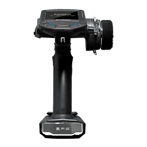
Page 9: Transmitter T10Px Nomenclature
Transmitter T10PX Nomenclature *The switches, dial, and trimmers in the figure are shown in the initial setting position. *Please be careful not to push the switch too strongly. Touch screen LCD Power switch Display switch Antenna Home button Edit button 1 ES1... -
Page 10: Power & Display Switch
Power & Display Switch The power switch and display switch are push switches. When the power switch (PWR) is held down, operation starts by transmitting radio waves. When the display switch (DSP) is held down, the transmitter side data can be checked and set. When the power is turned off, if the power switch or display switch is held down, the power is turned off. -
Page 11: Power Off
Power Off Forgotten Alarm & Auto Power Off At T10PX initialization, if steering wheel, throttle trigger, push switch, edit button, or other operation is not performed within 10 minutes, an audible alarm will sound and the message " Warning: Auto power off " will appear. -
Page 12: Digital Trim Operation
And USB port microSD port Rotating the antenna 90 ° reveals two ports. T10PX model data and telemetry log data can be saved by using a commercial microSD card. When T10PX software updates are released, the microSD card can also be used to make the update. -
Page 13: Trim/Dial Lock
Trim/Dial Lock T10PX setup and operation by digital trim DT1, DT2, DT3, DT4, DT5 and DT6 and dials DL1 can be prohibited. Setting When the HOME button is pressed for about 1 second at the initial screen, a confirma- tion beep is generated and the trim/dial lock display mark appears on the screen. -
Page 14: Wheel & Trigger Tension Adjustment
Wheel & Trigger Tension Adjustment Make this adjustment when you want to change the wheel or trigger spring’s tension. Adjustment Using hex wrench, adjust the wheel spring tension by turning the screw in- side the adjusting hole. - The spring is set to the weakest ten- sion at the factory. -
Page 15: Removal Of Trigger Unit
Removal Of Trigger Unit The trigger can be removed to replace the trigger spring. How to remove M2×8 Remove the fixing screw shown in the figure with a hex wrench. Be careful not to lose the screws. Note: M2×8 Be careful not to damage the case or wiring as the trigger unit is difficult M2×8 to remove. -
Page 16: Sw: Push Switch Pd: Paddle Switch
SW: Push switch PD: Paddle switch DL: Dial SSW: Slide switch The position of various switches. The assignment of each function can be changed for T10PX. SW5/DL1 SSW1 BPS: SW4 Grip Rubber Trigger Guard It is possible to make the narrow... -
Page 17: Battery Replacement Method
There is the dan- ger of collision if the power is cut while running (cruising). The use of Futaba genuine NiMH/LiFe or LiPo batteries is strongly recommended. -
Page 18: When Using Optional Battery
When Using The Optional Battery When using an optional rechargeable battery, replace the battery as described below. -Always use the optional FT2F1100B, FT2F1700B, FT2F2100B, HT5F1800 or LT- 2F2000B rechargeable battery. *Products for Europe cannot use NiMH / LiFe batteries. -The type of power source used must be selected through the system setting. -When the transmitter will not be used for a long time, remove the battery. -
Page 19: When Charging For The Optional Nimh
Remove the battery cover. instead of fully charged. Also be careful that the battery does not enter the over discharged state Disconnect the battery from the T10PX. due to self-discharge. Periodically (about every 3 months) charge the battery. In addition, always re-... -
Page 20: Method
When Charging For The Optional LiPo Battery To charge the battery, connect a type C USB cable to the Futaba optional USB AC adapter or a commercially available USB AC adapter (USB-A type 5 V-2 A) from the Lipo dedicated charging port. -
Page 21: Steering Wheel Arrangement
Steering Wheel Arrangement Changing the wheel position Modifying for left-hand use ● ● The wheel position can be offset by The wheel section left and right in- using the accessory APA wheel posi- stallation direction can be reversed. tion offset adapter. (Two lengths) 5°... -
Page 22: Exchange Procedure To Wheel Adaptor 32 Deg And Large Diameter Wheel
Exchange procedure to wheel adaptor 32 deg and large diameter wheel - Obtain hex wrench./ Remove the battery. Hold the wheel and remove the screw. (Using a hex wrench.) Pull off the wheel and wheel adapter. Steering wheel mounting screw Install the standard or large diameter steering wheel and the 32 degree wheel adapter using the screw. -
Page 23: Installing The Accessory Apa Steering Wheel Offset Adapter
Installing the accessory APA steering wheel offset adapter - Obtain hex wrench./ Remove the battery. Remove the 2 steering unit mounting screws (M3x12 screw). M3×12 (Using a hex wrench.) Remove the 2 mounting screws com- M3×12 pletely from the transmitter body. Gently remove the steering unit, without pulling excessively on the wiring. - Page 24 Fit the rear cover and attach the APA to M2×10 the steering housing with three M2x10 screws and one M2x6 screw. M2×10 APA uses the inside holes. The mounting angle in the direction of rotation can be adjusted. M2×10 M2×6 Normal screw position...
-
Page 25: Modifying For Left-Hand Use
Modifying for left-hand use Remove the 2 steering unit mounting screws (M3x12 screw). (Using a hex wrench.) M3×12 Remove the 2 mounting screws com- pletely from the transmitter body. M3×12 Gently remove the steering unit, without pulling excessively on the wiring. - Remove the steering unit slowly so that the internal wiring is not pulled unrea- sonably. - Page 26 Replace the steering unit bottom cover. • Slide it outward and pull it out. Steering unit bottom cover Install the rear unit to the connector on the opposite side of the transmitter body. • Install slowly so that the wiring is not pinched. Rear unit Rear unit fixing screw Fit the rear unit to the t r a n s m i t t e r b o d y...
-
Page 27: Angle Spacer
Angle Spacer The wheel mounting angle can be changed by using the optional angle spacer 5°. - The angle spacer use the included four M2x5 mm hex screws. - Obtain hex wrench./ Remove the battery. - The length of the screws used at each part differs. When reassembling the steering wheel unit, always use the specified screws. -
Page 28: When Removing The Paddle Switch
When Removing The Paddle Switch If the paddle switch interferes with operation, you can remove the paddle switch in the following ways. Remove the wheel unit from the trans- mitter according to "Installing the acces- sory APA steering wheel offset adapter". Wheel unit M2.6×8 Use a Phillips screwdriver to remove the... -
Page 29: Trigger Brake Lever Replacement
Trigger Brake Lever Replacement The trigger brake lever can be replaced with the optional trigger brake lever for 7PXR / 7PX / 4PM. *When the brake lever is changed, perform throttle side correction by adjuster function. Brake lever replacement Hold the trigger, remove the brake lever mount- ing screw using the hex wrench, and remove the brake lever. -
Page 30: Receiver Terminology
Under other conditions, the set will not operate, or the specified performance will not be displayed even if it operates. In addi- tion, it may cause trouble with servos and other equipment. Futaba will not be responsible for damage, etc. caused by combi-... -
Page 31: Receiver And Servo Connections
Installation Receiver And Servo Connections Connect the receiver and servos as shown below. Connect and install the receiver and servos in accordance with " Installation Safety Precautions " on the next page. The figure shown below is an example. The method of connecting the motor con- troller to the motor and battery depends on the motor controller used. -
Page 32: Installation Safety Precautions
Installation Safety Precautions Warning Receiver (receiver antenna) Do not cut or bundle the receiver antenna wire.(R404SBS) Do not bundle the receiver antenna wire together with the motor controller lead wire.(R404SBS) Keep the receiver antenna at least 1 cm away from motor, battery, and other wiring carrying heavy current. Do not use a metal receiver antenna holder on a plate made of metal, carbon, or other conductive mate- rial. - Page 33 Screw Damper Eyelet (or) Mechanical plate Nut (as required) When installing the servo, always install the accessory rubber grommet and grommet flush against the servo. A vibration-damping effect is not obtained if the rubber grommet and grommet are not installed correctly. Warning Servo Throw Operate each servo over its full stroke and be sure the linkage does not bind or come loose.
-
Page 34: Linking Method For F-4G System
FHSS", "Mini-Z"or "S-FHSS" is displayed. If not displayed, there is probably an abnormality or trouble so contact a Futaba Service Center. When a screen is displayed at the "DSP" side, "Display" is displayed. *Since the R404SBS(E) receiver supplied with the T10PX set uses the F-4G system, T10PX receiver setup must be set to F-4G. - Page 35 Bring the transmitter and receiver within 50 cm of each other (antennas do not touch) and turn on the receiver power. Touch [Link] on the transmitter T10PX screen, you will hear a chime sound and T10PX will enter the link mode for 20 seconds.
- Page 36 This ends reading of mutual ID and displays the mem- orized receiver ID number on the T10PX screen. Power cycle the receiver. If the "Re- ceiver not found" error screen is displayed, linking failed. Check the set contents and re- peat the linking operation.
-
Page 37: Menu Selection
Menu Selection Use the HOME button and the LCD screen touch panel to operate the screen. In this operation manual, the HOME button is indicated by the following symbols. Display Menu Screen Push the HOME button Press and hold the HOME or tap the touch panel. -
Page 38: Home/Es1/Es2/Es3 Button Setting �38
Home/ES1/ES2/ES3 Button Setting When you push the HOME button from the home screen, it moves to the Model se- lect screen at the factory shipping the HOME button. Pushing the HOME button on the menu screen or each setting screen will return you to the previous screen. Press and hold the HOME button on the menu screen or each setting screen to return to the Home screen. -
Page 39: The Set Value
This manual is a simplified version. Detailed of each function are not described. Refer to your countries distributor website for the full manual and update contents download. http://www.futabausa.com (http://www.rc.futaba.co.jp) FUTABA CORPORATION Hobby Radio Control Business Center Sales & Marketing Department 1080 Yabutsuka, Chosei-mura, Chosei-gun, Chiba-ken, 299-4395, Japan TEL: +81-475-32-6051, FAX: +81-475-32-2915 ©FUTABA CORPORATION... - Page 40 https://www.rc.futaba.co.jp...