Toshiba TOSVERT VF-AS1 Instruction Manual
The new generation high-performance inverter
Hide thumbs
Also See for TOSVERT VF-AS1:
- Instruction manual (334 pages) ,
- Function manual (49 pages) ,
- Option instruction manual (18 pages)
Table of Contents
Advertisement
Instruction Manual
The new generation
high-performance inverter
TM
TOSVERT
200V class
400V class 0.75~280kW
1.Make sure that this instruction manual is delivered to the end user of
the inverter unit.
2.Read this manual before installing or operating the inverter unit, and
store it in a safe place for reference.
AS1
VF-
0.4~75kW
NOTICE
E6581301
I I
Safety
precautions
II II
Introduction
Contents
1 1
Read first
2 2
Connection
equipment
3 3
Operations
4 4
Searching and
setting parameters
5 5
Basic
parameters
6 6
Extended
parameters
7 7
Operation with
external signal
8 8
Monitoring the
operation status
9 9
Taking measures
to satisfy the
CE/UL/CSA standards
10 10
Selection of
peripheral
devices
1 1 1 1
Table of
parameters
12 12
Specifications
13 13
Before making a
service call
14 14
Inspection and
maintenance
15 15
Warranty
16 16
Disposal of
the inverter
Advertisement
Table of Contents

Related Manuals for Toshiba TOSVERT VF-AS1


Summary of Contents for Toshiba TOSVERT VF-AS1
- Page 1 E6581301 Safety precautions II II Introduction Contents Read first Instruction Manual Connection equipment Operations The new generation Searching and setting parameters high-performance inverter Basic parameters TOSVERT Extended parameters Operation with external signal Monitoring the operation status Taking measures to satisfy the CE/UL/CSA standards 10 10 Selection of...
- Page 2 E6581301 I. Safety precautions The items described in these instructions and on the inverter itself are very important so that you can use the inverter safely prevent injury to yourself and other people around you as well as prevent damage to property in the area. Thoroughly familiarize yourself with the symbols and indications shown below and then continue to read the manual.
- Page 3 E6581301 General Operation Danger Reference ・Never disassemble, modify or repair. This can result in electric shock, fire and injury. For repairs, call your sales agency. Disassembly prohibited ・Never remove the front cover when power is on or open door if enclosed in a cabinet. The unit contains many high voltage parts and contact with them will result in electric shock.
- Page 4 Operation cannot be stopped immediately by the inverter alone, thus risking an accident or injury. ・All options used must be those specified by Toshiba. 1.4.4 The use of any other option may result in an accident.
- Page 5 E6581301 Wiring Danger Reference ・Do not connect input power to the output (motor side) terminals (U/T1,V/T2,W/T3). That will destroy the inverter and may result in fire. ・Do not connect resistors to the DC terminals (across PA-PC or PO-PC). That may cause a fire. Prohibited Connect resistors as directed by the instructions for “Installing separate braking resistors.”...
- Page 6 E6581301 Operations Danger Reference ・Do not touch inverter terminals when electrical power is applied to the inverter even if the motor is stopped. Touching the inverter terminals while power is connected to it may result in electric shock. ・Do not touch switches when thands are wet and do not try to clean the inverter with a damp cloth.
- Page 7 E6581301 Maintenance and inspection Danger Reference 14.2 ・Never replace any part by yourself. This could be a cause of electric shock, fire and bodily injury. To replace parts, call the local sales agency. Prohibited ・The equipment must be inspected every day. If the equipment is not inspected and maintained, errors and malfunctions may not be discovered which could lead to accidents.
- Page 8 E6581301 II. Introduction Thank you for your purchase of the Toshiba “TOSVERT VF-AS1” industrial inverter.
-
Page 9: Table Of Contents
E6581301 - Contents - I. Safety precautions ・・・・・・・・・・・・・・・・・・・・・・・・・・・・・・・・・・・・・・・・・・・・・・・・・・・・・・・・・・・・・・・・・・・・・・・・・・・・・・・・・・・・ II. Introduction ・・・・・・・・・・・・・・・・・・・・・・・・・・・・・・・・・・・・・・・・・・・・・・・・・・・・・・・・・・・・・・・・・・・・・・・・・・・・・・・・・・・・・・・・・ Read first ・・・・・・・・・・・・・・・・・・・・・・・・・・・・・・・・・・・・・・・・・・・・・・・・・・・・・・・・・・・・・・・・・・・・・・・・・・・・・・・・・・・・・・・ Check product purchase ・・・・・・・・・・・・・・・・・・・・・・・・・・・・・・・・・・・・・・・・・・・・・・・・・・・・・・・・・・・・・・・・・・・・・・ Contents of the product ・・・・・・・・・・・・・・・・・・・・・・・・・・・・・・・・・・・・・・・・・・・・・・・・・・・・・・・・・・・・・・・・・・・・・・・ Names and functions ・・・・・・・・・・・・・・・・・・・・・・・・・・・・・・・・・・・・・・・・・・・・・・・・・・・・・・・・・・・・・・・・・・・・・・・・・ 1.3.1 Outside view・・・・・・・・・・・・・・・・・・・・・・・・・・・・・・・・・・・・・・・・・・・・・・・・・・・・・・・・・・・・・・・・・・・・・・・・・・・・・ 1.3.2 Main circuit, control power supply and control circuit terminal boards ・・・・・・・・・・・・・・・・・・・・・・・・・・・・ 1.3.3 Detaching the terminal board front cover (in case of models 200V-15kW or smaller, 400V-18.5kW or smaller) ・・・・・・・・・・・・・・・・・・・・・・・・・・・・・・・・・・・・・・・・・・・・・・・・・・・・・・・・・・・・・・・・・・... - Page 10 E6581301 5.15 Changing the display unit % to A (ampere)/V (volt)・・・・・・・・・・・・・・・・・・・・・・・・・・・・・・・・・・・・・・・・・・・・・・・・ E-25 5.16 Meter setting and adjustment ・・・・・・・・・・・・・・・・・・・・・・・・・・・・・・・・・・・・・・・・・・・・・・・・・・・・・・・・・・・・・・・・・・ E-26 5.17 PWM carrier frequency ・・・・・・・・・・・・・・・・・・・・・・・・・・・・・・・・・・・・・・・・・・・・・・・・・・・・・・・・・・・・・・・・・・・・・・・ E-31 5.18 Trip-less intensification ・・・・・・・・・・・・・・・・・・・・・・・・・・・・・・・・・・・・・・・・・・・・・・・・・・・・・・・・・・・・・・・・・・・・・・・ E-32 5.18.1 Auto-restart (Restart during coasting) ・・・・・・・・・・・・・・・・・・・・・・・・・・・・・・・・・・・・・・・・・・・・・・・・・・・・・・・ E-32 5.18.2 Regenerative power ride-through control/Deceleration stop during power failure/ Synchronized acceleration/deceleration・・・・・・・・・・・・・・・・・・・・・・・・・・・・・・・・・・・・・・・・・・・・・・・・・・・・・・・・・...
- Page 11 E6581301 6.21 Stop position control function ・・・・・・・・・・・・・・・・・・・・・・・・・・・・・・・・・・・・・・・・・・・・・・・・・・・・・・・・・・・・・・・・・・ F-34 6.22 Setting motor constants ・・・・・・・・・・・・・・・・・・・・・・・・・・・・・・・・・・・・・・・・・・・・・・・・・・・・・・・・・・・・・・・・・・・・・・・ F-36 6.23 Motor current stabilization adjustment ・・・・・・・・・・・・・・・・・・・・・・・・・・・・・・・・・・・・・・・・・・・・・・・・・・・・・・・・・・・ F-39 6.24 Torque control ・・・・・・・・・・・・・・・・・・・・・・・・・・・・・・・・・・・・・・・・・・・・・・・・・・・・・・・・・・・・・・・・・・・・・・・・・・・・・・・ F-39 6.24.1 Torque command ・・・・・・・・・・・・・・・・・・・・・・・・・・・・・・・・・・・・・・・・・・・・・・・・・・・・・・・・・・・・・・・・・・・・・・・・ F-39 6.24.2 Speed limits in torque control mode・・・・・・・・・・・・・・・・・・・・・・・・・・・・・・・・・・・・・・・・・・・・・・・・・・・・・・・・・ F-40 6.24.3 Torque bias and load sharing gain ・・・・・・・・・・・・・・・・・・・・・・・・・・・・・・・・・・・・・・・・・・・・・・・・・・・・・・・・・・...
- Page 12 E6581301 6.36.8 Torque-related parameters for panel operation ・・・・・・・・・・・・・・・・・・・・・・・・・・・・・・・・・・・・・・・・・・・・・・・ F-71 6.37 Tracing functions・・・・・・・・・・・・・・・・・・・・・・・・・・・・・・・・・・・・・・・・・・・・・・・・・・・・・・・・・・・・・・・・・・・・・・・・・・・・・ F-71 6.38 Communication function ・・・・・・・・・・・・・・・・・・・・・・・・・・・・・・・・・・・・・・・・・・・・・・・・・・・・・・・・・・・・・・・・・・・・・・ F-75 6.38.1 2-wire RS485/4-wire RS485 ・・・・・・・・・・・・・・・・・・・・・・・・・・・・・・・・・・・・・・・・・・・・・・・・・・・・・・・・・・・・・・・ F-75 6.38.2 Open network option ・・・・・・・・・・・・・・・・・・・・・・・・・・・・・・・・・・・・・・・・・・・・・・・・・・・・・・・・・・・・・・・・・・・・・ F-81 6.39 My function・・・・・・・・・・・・・・・・・・・・・・・・・・・・・・・・・・・・・・・・・・・・・・・・・・・・・・・・・・・・・・・・・・・・・・・・・・・・・・・・・・ F-81 6.40 Instruction manuals for optionally available devices and special functions ・・・・・・・・・・・・・・・・・・・・・・・・・・・・・・・・・・・・ F-82 Operation with external signal ・・・・・・・・・・・・・・・・・・・・・・・・・・・・・・・・・・・・・・・・・・・・・・・・・・・・・・・・・・・・・・・・・・・・・...
- Page 13 E6581301 Inspection and maintenance ・・・・・・・・・・・・・・・・・・・・・・・・・・・・・・・・・・・・・・・・・・・・・・・・・・・・・・・・・・・・・・・・・・・・・・・ 14.1 Regular inspection ・・・・・・・・・・・・・・・・・・・・・・・・・・・・・・・・・・・・・・・・・・・・・・・・・・・・・・・・・・・・・・・・・・・・・・・・・・・ 14.2 Periodical inspection・・・・・・・・・・・・・・・・・・・・・・・・・・・・・・・・・・・・・・・・・・・・・・・・・・・・・・・・・・・・・・・・・・・・・・・・・・ 14.3 Making a call for servicing ・・・・・・・・・・・・・・・・・・・・・・・・・・・・・・・・・・・・・・・・・・・・・・・・・・・・・・・・・・・・・・・・・・・・・ 14.4 Keeping the inverter in storage ・・・・・・・・・・・・・・・・・・・・・・・・・・・・・・・・・・・・・・・・・・・・・・・・・・・・・・・・・・・・・・・・・ Warranty ・・・・・・・・・・・・・・・・・・・・・・・・・・・・・・・・・・・・・・・・・・・・・・・・・・・・・・・・・・・・・・・・・・・・・・・・・・・・・・・・・・・・・・・・ Disposal of the inverter・・・・・・・・・・・・・・・・・・・・・・・・・・・・・・・・・・・・・・・・・・・・・・・・・・・・・・・・・・・・・・・・・・・・・・・・・・・・...
-
Page 14: Read First
E6581301 1. Read first Check product purchase Before using the product you have purchased, check to make sure that it is exactly what you ordered. Warning Use an inverter that conforms to the specifications of the power supply and three-phase induction motor being used. -
Page 15: Names And Functions
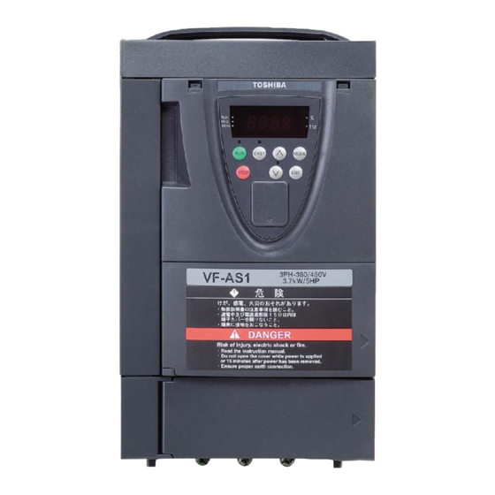
E6581301 1. 3 Names and functions 1.3.1 Outside view Up key RUN lamp EASY key [Note] EASY key lamp % lamp Lights when an ON Lights when the unit is %. Press this key to control Lights when the EASY command is issued but no the function assigned with key is enabled. - Page 16 E6581301 Protective cover on the top [Note] Wiring port Ventilation slit Name plate Cooling fun [Bottom view] [Side view] Note: Remove this cover when installing the inverter side by side with other inverters where the ambient temperature will rise above 40°C. ⇒ For more details, refer to Section 1.4.4.
-
Page 17: Main Circuit, Control Power Supply And Control Circuit Terminal Boards
E6581301 1.3.2 Main circuit, control power supply and control circuit terminal boards 1) Main circuit terminal board VFAS1-2004PL~2015PL VFAS1-4007PL~4022PL Shorting-bar M4 screw Grounding capacitor disconnection switch Grounding terminal (M5 screw) Screw hole for EMC plate VFAS1-2022PL,2037PL VFAS1-403 PL Shorting-bar M4 screw Grounding capacitor disconnection switch Grounding terminal... - Page 18 E6581301 VFAS1-2075PL VFAS1-4110PL Shorting-bar M4 screw Grounding capacitor disconnection switch Grounding terminal (M5 screw) Screw hole for EMC plate VFAS1-2110PM, 2150PM VFAS1-4150PL, 4185PL Grounding capacitor disconnection switch Shorting-bar M6 screw Grounding terminal (M5 screw) Screw hole for EMC plate VFAS1-2185PM, 2220PM VFAS1-4220PL M8 screw Shorting-bar...
- Page 19 E6581301 VFAS1-4300PL,4370PL M8 screw Shorting-bar Grounding capacitor disconnection switch Screw hole for EMC plate Grounding terminal (M5 screw) VFAS1-2300PM~2450PM 端子台配置 VFAS1-4450PL~4750PL M12 screw Shorting-bar Grounding capacitor disconnection switch Screw hole for EMC plate Grounding terminal (M8 screw)
- Page 20 E6581301 VFAS1-2550P VFAS1-4900PC M12 screw M10 screw Grounding capacitor M8 screw disconnection switch Grounding terminal(M10 screw) VFAS1-2750P VFAS1-4110KPC M12 screw M10 screw Grounding capacitor disconnection switch M4 screw M8 screw Grounding terminal(M10 screw) VFAS1-4132K PC M10 screw Grounding capacitor disconnection screw M10 screw M8 screw...
- Page 21 E6581301 VFAS1-4160KPC M12 screw Grounding capacitor disconnection screw M10 screw M10 screw Grounding terminal(M10 screw) VFAS1-4200KPC~4280KPC M12 screw Grounding capacitor disconnection screw M12screw Grounding terminal(M12 screw) 2) Control power supply backup terminal The control circuit of the VF-AS1 is powered from the main circuit. To supply the control circuit with power when the main circuit is not energized, a control circuit backup device (optional CPS002Z) needs to be connected to the inverter control terminals (+SU, CC) shown in the figure below.
- Page 22 E6581301 3) Grounding capacitor disconnection method Danger If you are using an inverter with a capacity of 400V-3.7kW or less or with a capacity between 400V-5.5kW and 400V-18.5kW, if the cables connecting the inverter to the motor is 100 m or Prohibited more in length, and if the grounding capacitor is detached from the inverter, be sure to set the carrier frequency () at 4kHz or less.
- Page 23 E6581301 400V/132kW models and larger: Grounding capacitor switching screw To connect and ground the capacitor, fix to part A shown in the figure on the left with the grounding capacitor switching screw. (Factory default position) To detach the capacitor to block it from being grounded, fix to part B shown in the figure on the left with the grounding capacitor switching...
-
Page 24: Detaching The Terminal Board Front Cover (In Case Of Models 200V-15Kw Or Smaller, 400V-18.5Kw Or Smaller
E6581301 1.3.3 Detaching the terminal board front cover (in case of models 200V-15kW or smaller, 400V-18.5kW or smaller) To wire the terminal board for models 200V-15kW or smaller and 400V-18.5kW or smaller, remove the terminal board cover in line with the steps given below. Main circuit terminal board cover 90°... -
Page 25: Notes On The Application
E6581301 Notes on the application 1.4.1 Motors Keep the following in mind when using the VF-AS1 to drive a motor. Warning Use an inverter that conforms to the specifications of power supply and three-phase induction motor being used. If the inverter being used does not conform to those specifications, not only will the three-phase induction motor not rotate correctly, but it may cause serious accidents through Mandatory overheating and fire. - Page 26 E6581301 Braking a motor when power supply is lost A motor with its power cut off goes into freewheel, and does not stop immediately. To stop the motor quickly as soon as the power is cut off install an auxiliary brake. There are different kinds of brake devices, both electrical and mechanical.
-
Page 27: Inverters
E6581301 1.4.2 Inverters Protecting inverters from overcurrent The inverter has an overcurrent protection function. The programmed current level is set to the inverter's maximum applicable motor. If the motor used has a small capacity, the stall prevention level, overcurrent level and the motor electronic thermal protection must be readjusted. -
Page 28: What To Do About The Leak Current
E6581301 1.4.3 What to do about the leak current Warning Current may leak through the inverter's input/output wires because of insufficient electrostatic capacity on the motor with bad effects on peripheral equipment. The leakage current's value is affected by the carrier frequency and the length of the input/output wires. - Page 29 E6581301 Remedies: Use the electronic thermal overload built into the inverter. The setting of the electronic thermal overload is done using parameter or . Reduce the inverter's PWM carrier frequency. However, that will increase the motor's acoustic noise. The setting of PWM carrier frequency is done with the parameter ...
-
Page 30: Installation
E6581301 1.4.4 Installation Installation environment The VF-AS1 Inverter is an electronic control instrument. Take full consideration to installing it in the proper operating environment. Danger ・ Do not place any inflammable substances near the VF-AS1 Inverter. If an accident occurs in which flames are emitted, this could lead to fire. Prohibited ・... - Page 31 Operation cannot be stopped immediately by the inverter alone, thus risking an accident or injury. ・ All options used must be those specified by Toshiba. The use of any other option may result in an accident.
- Page 32 E6581301 Installation place Install the inverter in a well-ventilated indoor place and mount it on a flat metal plate in portrait orientation. If you are installing more than one inverter, the separation between inverters should be at least 5cm, and they should be arranged in horizontal rows.
- Page 33 E6581301 200V 18.5~45kW 40°C: (a) 400V 37~75kW When the upper protection cover is removed under condition (a) 100% 50°C: (a) When the upper protection cover is removed under condition (a) 60°C: (a) When the upper protection cover is removed under condition (a) 2.5kHz 4kHz 8kHz...
- Page 34 E6581301 Panel designing taking into consideration the effects of noise The inverter generates high frequency noise. When designing the control panel setup, consideration must be given to that noise. Examples of measures are given below. ・ Wire so that the main circuit wires and the control circuit wires are separated. Do not place them in the same conduit, do not run them parallel, and do not bundle them.
-
Page 35: Connection Equipment
E6581301 2. Connection equipment Danger ・Never disassemble, modify or repair. This can result in electric shock, fire and injury. For repairs, call your sales agency. Disassembly prohibited ・Don't stick your fingers into openings such as cable wiring hole and cooling fan covers. This can result in electric shock or other injury. - Page 36 E6581301 Warning ・Do not attach devices with built-in capacitors (such as noise filters or surge absorber) to the output (motor side) terminal. This could cause a fire. Prohibited Preventing radio noise To prevent electrical interference such as radio noise, separately bundle wires to the main circuit's power terminals (R/L1, S/L2, T/L3) and wires to the motor terminals (U/T1, V/T2, W/T3).
-
Page 37: Standard Connections
E6581301 Standard connections Danger ・Do not connect input power to the output (motor side) terminals (U/T1, V/T2, W/T3). Connecting input power to the output could destroy the inverter or cause a fire. ・Do not connect a regenerative braking resistor to any DC terminal (between PA and PC or between PO and PC). - Page 38 E6581301 [Standard connection diagram - sink] The figure below shows an example of typical wiring in the main circuit of a 200V 0.4-75kW/400V 0.75-160kW inverter. Main circuit power source 400V class: 200V class: 0.75~75kW Three-phase 380~480V-50/60Hz 0.4~45kW Three-phase 200~240V-50/60Hz 90~160kW Three-phase 380~440V-50Hz 55kW, 75kW Three-phase 200~220V-50Hz Three-phase 380~480V-60Hz...
- Page 39 E6581301 [Standard connection diagram - sink] The figure below shows an example of typical wiring in the main circuit of a 400V 200-280kW inverter. Main circuit power source 400V class: Three-phase 380~440V-50Hz Three-phase 380~480V-60Hz Motor 400/200V transformer (400V class only) Forward run signal Reverse run signal Standby...
- Page 40 E6581301 [Standard connection diagram - source] The figure below shows an example of typical wiring in the main circuit of a 200V 0.4-75kW/400V 0.75-160kW inverter. Main circuit power source 200V class: 400V class: 0.4~45kW Three-phase 200~240V-50/60Hz 0.75~75kW Three-phase 380~480V-50/60Hz 55kW, 75kW Three-phase 200~220V-50Hz 90~160kW Three-phase 380~440V-50Hz Three-phase 200~240V-60Hz...
- Page 41 E6581301 [Standard connection diagram - source] The figure below shows an example of typical wiring in the main circuit of a 400V 200-280kW inverter. Main circuit power source 400V class: Three-phase 380~440V-50Hz Three-phase 380~480V-60Hz Motor 400/200V transformer (400V class only) Forward run signal Reverse run signal Standby...
-
Page 42: Description Of Terminals
E6581301 Description of terminals 2.3.1 Main circuit terminals This diagram shows an example of wiring of the main circuit. Use options if necessary. Power supply and motor connections VF-AS1 Connect the power Connect the motor Power supply cables to RL1, S/L2, interconnect cables to and T/L3. -
Page 43: Control Circuit Terminals (Sink Logic (Minus Common:cc
E6581301 2.3.2 Control circuit terminals sink logic (minus common:CC) The control circuit terminal board is common to all equipment. Shorting bar between ST-CC Terminal Input/ Electrical Function Inverter internal circuits symbol output specifications Shorting across F-CC causes forward Input rotation; open causes deceleration stop. Voltage free contact (Across ST-CC is short state.) input... - Page 44 E6581301 Terminal Input/ Electrical Function Inverter internal circuits symbol output specifications 10Vdc Constant voltage circuit Output Analog input setting power output (Permissible load current:10mAdc) SW4: Multifunction programmable analog input 2.2k 12.7k terminal when SW4 is in the RR position. 10Vdc RR/S4 Input Standard default setting:0~10Vdc input and...
- Page 45 E6581301 SW settings Default setting Function SOURCE SINK Setting for using the inverter’s internal power supply in sink logic ● mode INT/PLC SOURCE SINK Setting for using the inverter’s external power supply in sink logic mode INT/PLC SOURCE SINK Setting for operating the inverter in source logic mode INT/PLC Setting for using the analog output terminal FM to output current 0-10V...
- Page 46 E6581301 Sink logic (negative logic)/source logic (positive logic)・・Switching I/O terminal Current flowing out turns control input terminals on. These are called sink logic terminals. The method generally used in Europe is source logic in which current flowing into the input terminal turns it on. Sink logic terminals and source logic terminals are sometimes referred to as negative logic terminals and positive logic terminals, respectively.
- Page 47 E6581301 Sink logic/source logic (When an external power supply is used) The PLC terminal is used to connect to an external power supply or to insulate a terminal from other input or output terminals. Use the slide switch SW1 to switch between sink logic and source logic configurations. <Examples of connections when an external power supply is used>...
-
Page 48: Serial Rs485 Communication Connector
E6581301 2.3.3 Serial RS485 communication connector The VF-AS1 is equipped with two connectors: a two-wire RS485 connector (on the front panel of the main unit) and a four-wire RS485 connector. The two wire RS485 connector is used to connect an optional peripheral device (such as extended control device or computer) to the inverter. - Page 49 E6581301 Recommended wiring materials Wiring Recommended products materials RJ45 connector Manufacturer: Tyco Electronics AMP K.K. Connector Type: 5-569278-3 (single wire), 5-558530-3 (twisted wire) Product name: High performance modular plug (wire range:AWG24) Twisted-pair cable compliant with 24AWG Category 5 Manufacturer: Showa electric Wire & Cable Co., LTD Cable Type: GECL-9004 Product name: 100Mbps-capable twisted-pair cable 24AWG x 4P (single wire)
-
Page 50: Operations
E6581301 3. Operations This section explains the basics of operation of the inverter. Check the following again before starting operation. 1) Are all wires and cables connected correctly? 2) Does the supply voltage agree with the rated input voltage? Danger ・Do not touch inverter terminals when electrical power is applied to the inverter even if the motor is stopped. -
Page 51: Setting/Monitor Modes
E6581301 Setting/monitor modes The VF-AS1 has the following three setting/monitor modes. Standard monitor mode The standard inverter mode. This mode is enabled when inverter power goes on. This mode is for monitoring the output frequency and setting the frequency reference value. If also displays information about status alarms during running and trips. -
Page 52: Simplified Operation Of The Vf-As1
E6581301 Simplified operation of the VF-AS1 On of three operation modes can be selected: terminal board operation, operation panel and combination of both. ⇒ For other operation modes, refer to Section 5.5. Terminal board mode :Operation by means of external signals Operation panel mode :Operation by pressing keys on the operation panel Operation panel + terminal board mode... - Page 53 E6581301 Frequency setting 1) Setting the frequency using potentiometer Potentiometer The operation frequency by potentiometer (1~10kΩ- 1/4W ) for setting ⇒ Refer to Section 7.3 for details of adjustment. :Frequency settings RR/S4 80Hz With potentiometer Frequency [Parameter setting] Set the “basic parameter frequency setting mode selection 1” parameter to . (There is no need to set this parameter before the first use after purchase.) 2) Setting the frequency using input voltage (0~10V) Voltage signal...
- Page 54 E6581301 4) Setting the frequency using input voltage (0~10Vdc) Voltage signal Voltage signal (0~10V) for setting the operation frequency ⇒ Refer to Section 7.3 for details of adjustment. VI/II :Voltage signal 0-10Vdc 60Hz Frequency 10Vdc 0Vdc [Parameter setting] *Necessary to change the VI/II input point 1 setting . Set the “extended parameter analog input VI/II voltage/current switching”...
- Page 55 E6581301 Key operated LED display Operation Press either the key or the key to change to the parameter group . Press the ENTER key to display the first extended parameter . Press the key to change to . Pressing the ENTER key allows the reading of parameter setting.
-
Page 56: Panel Operation
E6581301 3.2.2 Panel operation This section describes how to start/stop the motor, and set the operation frequency with the operating panel. :Set frequency Example of basic connection MCCB :Motor starts Motor R/L1 U/T1 Power S/L2 V/T2 :Stop the motor supply STOP T/L3 W/T3... - Page 57 E6581301 Example of operation panel control Key operated LED display Operation The running frequency is displayed. (When standard monitor display selection = [Operation frequency]) Set the operation frequency. Press the ENTER key to save the operation frequency. and the ⇔...
-
Page 58: Searching And Setting Parameters
E6581301 4. Searching and setting parameters There are two types of setting mode quick mode and standard setting mode. Quick mode : EASY Key: ON Eight frequently used basic parameters are just displayed. Quick mode (EASY) Title Function Automatic function setting V/f control mode selection ... -
Page 59: How To Set Parameters
E6581301 How to set parameters This section explains how to set parameters, while showing how parameters are organized in each setting monitor mode. 4.1.1 Setting parameters in the selected quick mode To place the inverter in this mode, press the key (the LED lights up), and then press the key. -
Page 60: Setting Parameters In The Standard Setting Mode
E6581301 4.1.2 Setting parameters in the standard setting mode Press the key to place the inverter in this mode. MODE How to set basic parameters Selects parameter to be changed. (Press the key.) Reads the programmed parameter setting. (Press the key.) Change the parameter value. -
Page 61: Functions Useful In Searching For A Parameter Or Changing A Parameter Setting
E6581301 Adjustment range and display of parameters An attempt has been made to assign a value that is higher than the programmable range. Or, as a result of changing other parameters, the programmed value of the parameter that is now selected exceeds the upper limit.... -
Page 62: Basic Parameters
E6581301 5. Basic parameters This parameter is a basic parameter for the operation of the inverter. ⇒ Refer to Section 11, Table of parameters. History function : History function • Function Automatically searches for 5 latest parameters that are programmed with values different from the standard default setting and displays them in the . -
Page 63: Setting Acceleration/Deceleration Time
E6581301 Setting acceleration/deceleration time : Automatic acceleration/deceleration : Acceleration time 1 : Deceleration time 1 • Function 1) For acceleration time programs the time that it takes for the inverter output frequency to go from 0Hz to maximum frequency . -
Page 64: Manually Setting Acceleration/Deceleration Time
E6581301 5.2.2 Manually setting acceleration/deceleration time Set acceleration time from 0 (Hz) operation frequency to maximum frequency and deceleration time as the time when operation frequency goes from maximum frequency to 0 (Hz). Output frequency [Hz] = (Manual setting) Time [s] ... - Page 65 E6581301 1) Increasing torque automatically according to the load Set the automatic torque boost = (automatic torque boost+auto-tuning) Automatic torque boost = detects load current in all speed ranges and automatically adjusts voltage output from inverter. This gives steady torque for stable runs. Note 1: The same characteristic can be obtained by setting the V/f control mode selection parameter ...
-
Page 66: Setting Parameters By Operating Method
E6581301 Setting parameters by operating method : Automatic function setting • Function Automatically programs all parameters (parameters described below) related to the functions by selecting the inverter's operating method. The major functions can be programmed simply. [Parameter setting] Title Function Adjustment range Default setting... -
Page 67: Selection Of Operation Mode
E6581301 Voltage/current switching by means of an external terminal (=) Switching between remote and local (different frequency commands) can be performed by turning on or off the S3 terminal. In that case, apply a voltage via the RR/S4 terminal and a current via the VI/II terminal. S3-CC OFF: The frequency is set according to the voltage applied to the RR/S4 terminal. - Page 68 E6581301 <Frequency setting mode selection> [Parameter setting] Title Function Adjustment range Default setting :VI/II (voltage/current input) :RR/S4 (potentiometer/voltage input) :RX (voltage input) :Operation panel input enabled(LED/LCD option input enabled) : Operation panel RS485 (2-wire) communication input Frequency setting mode :Internal RS485 (4-wire) communication input ...
- Page 69 E6581301 The functions assigned to the following control input terminals (contact input: ⇒ Refer to Section 7.2) are always activated regardless of the settings of the command mode selection and frequency setting mode selection 1 . • Reset terminal (default setting: RES, valid only for tripping) •...
- Page 70 E6581301 2) Setting the run and stop frequencies (forward run, reverse run and coast stop) by means of external signals and setting the operation frequency with the operation panel Title Function Default setting Run/stop : ON/OFF of terminals F-CC/R-CC Command mode selection ...
- Page 71 E6581301 4) Setting the run, stop and operation frequencies (forward run, reverse run and coast stop) by means of external signals (default setting) Title Function Setting value Run/stop :ON/OFF of terminals F-CC/R-CC Command mode Speed command :External signal input :Terminal input ...
-
Page 72: Selecting Control Mode
E6581301 Selecting control mode : V/f control mode selection • Function With “VF-AS1,” the V/f controls shown below can be selected. 0 Constant torque characteristics 1 Voltage decrease curve 2 Automatic torque boost *1 3 Sensorless vector control 1 4 Sensorless vector control 2 5 V/f 5-point setting 6 PM control... - Page 73 to (Constant torque characteristics) and increase torque manually. Motor constant must be set. If the motor you are using is a 4P Toshiba standard motor and if it has the same capacity as the inverter, there is basically no need to set the motor constant.
- Page 74 (4) Effective in producing high motor torque at low speed. Motor constant must be set. If the motor you are using is a 4P Toshiba standard motor and if it has the same capacity as the inverter, there is basically no need to set the motor constant.
- Page 75 cannot be set to in such a case. Motor constant must be set. If the motor you are using is a 4P Toshiba standard motor and if it has the same capacity as the inverter, there is basically no need to set the motor constant.
-
Page 76: Manual Torque Boost-Increasing Torque Boost At Low Speeds
E6581301 Manual torque boost–increasing torque boost at low speeds : Manual torque boost • Function If torque is inadequate at low speeds, increase torque by raising the torque boost rate with this parameter. Base frequency voltage 1 [V]/[%] Output frequency [Hz] Base frequency... -
Page 77: Maximum Frequency
E6581301 Maximum frequency : Maximum frequency • Function 1) Programs the range of frequencies output by the inverter (maximum output values). 2) This frequency is used as the reference for acceleration/deceleration time. Output frequency [Hz] In case of =80Hz •... -
Page 78: Setting Frequency Command Characteristics
E6581301 5.11 Setting frequency command characteristics ~ , : VI/II point setting ~ , : RR/S4 point setting ~ : RX point setting ~ : ~ : It sets up, when using the optional circuit board. ... - Page 79 E6581301 Example of preset speed contact input signal : ON –: OFF (Speed commands other than preset speed commands are valid when all are OFF) Preset speed Terminal S1-CC – – – – – – – S2-CC – – – –...
- Page 80 E6581301 Below is an example of 7-step speed operation with standard default setting. Output frequency [Hz] Time ST-CC F-CC S1-CC S2-CC S3-CC Example of 7-step speed operation 4)Setting the operation mode An operation mode can be selected for each preset speed. Operation mode setting Title Function...
-
Page 81: Selecting Forward And Reverse Runs (Operation Panel Only
E6581301 5.13 Selecting forward and reverse runs (operation panel only) : Forward/reverse run selection • Function Program the direction of rotation of the motor when the running and stopping are made using the RUN key and STOP key on the operation panel. Valid when ... -
Page 82: Setting The Electronic Thermal
E6581301 5.14 Setting the electronic thermal : Motor electronic thermal protection level 1 : Electronic thermal protection characteristic selection : Overload reduction starting frequency : Motor 150%-overload time limit : Inverter overload selection • Function This parameter allows selection of the appropriate electronic thermal protection characteristics according to the particular rating and characteristics of the motor. - Page 83 E6581301 Setting of motor electronic thermal protection level 1 If the capacity of the motor is smaller than the capacity of the inverter, or the rated current of the motor is smaller than the rated current of the inverter, adjust the electronic thermal protection level 1 so that it fits the motor's rated current.
- Page 84 E6581301 Setting of motor electronic thermal protection level 1 If the capacity of the motor is smaller than the capacity of the inverter, or the rated current of the motor is smaller than the rated current of the inverter, adjust the electronic thermal protection level 1 so that it fits the motor's rated current.
- Page 85 E6581301 3) Inverter overload characteristics Set to protect the inverter unit. Cannot be turned off by parameter setting. The inverter has two overload detecting functions, which can be switched from one to another using parameter (inverter overload detection mode selection). [Parameter setting] Title Function...
-
Page 86: Changing The Display Unit % To A (Ampere)/V (Volt
E6581301 5.15 Changing the display unit % to A (ampere)/V (volt) : Current/voltage display mode • Function These parameters are used to change the unit of monitor display. % ⇔A (ampere)/V (volt) Example of setting During the operation of the VFAS1-2037PL (rated current 16.6A) at the rated load (100% load), units are displayed as follows: 1) Display in percentage terms 2) Display in amperes/volts... -
Page 87: Meter Setting And Adjustment
E6581301 5.16 Meter setting and adjustment : FM terminal meter selection : FM terminal meter adjustment : FM voltage/current output switching : Inclination characteristic of FM output : FM bias adjustment : AM terminal meter selection ... - Page 88 E6581301 [Terminal FM-related parameters] Adjustment Title Function Adjustment range Default setting level : Operation frequency : Operation frequency command : Output current : DC voltage : Output voltage : Compensated frequency *2 : Speed feedback (real-time value) : Speed feedback (1 second filter) : Torque : Torque command : Torque current...
- Page 89 E6581301 [Terminal AM-related parameters] Title Function Adjustment range Default setting AM terminal meter selection Same as (29:AM output disabled) AM terminal meter – – adjustment AM output gradient :Negative gradient (downward-sloping), characteristic :Positive gradient (upward-sloping) AM bias adjustment –~% ...
- Page 90 E6581301 Meter adjustment 2 when the inverter is at rest (adjustment by setting () to : Fixed output 2) This function is useful especially in adjusting the current monitor, and the levels of items (a) to (d) in the list on the previous page are adjusted, as described below.
-
Page 91: Pwm Carrier Frequency
E6581301 Gradient bias adjustment of analog monitor output Here is an example of the adjustment of output from 0-20mA → 20-0mA, 4-20mA using the FM terminal. =1, =0 =1, =20 (mA) (mA) 100% 100% =0, =100 =0, =100 (mA) (mA) small large 100%... - Page 92 E6581301 * Setting the PWM carrier frequency larger than the default value, reduction of rated current is needed. For details, refer to figure and table below. Load Load factor factor carrier frequency carrier frequency ( ( 200V model 400V model Carrier frequency Carrier frequency...
-
Page 93: Trip-Less Intensification
E6581301 5.18 Trip-less intensification 5.18.1 Auto-restart (Restart during coasting) : Auto-restart control selection Warning • Do not go near motors and equipment. Motors and equipment that have stopped temporarily after momentary power failure will restart suddenly after recovery. This could result in unexpected injury. Mandatory •... - Page 94 E6581301 2) Restarting motor during coasting (Motor speed search function) Motor speed F-CC ST-CC =: This function operates after the ST-CC terminal connection has been opened first and then connected again. Title Function Adjustment range Default setting Setting value :Disabled :At auto-restart after momentary stop Auto-restart control ...
-
Page 95: Regenerative Power Ride-Through Control/Deceleration Stop During Power Failure/Synchronized Acceleration/Deceleration
E6581301 5.18.2 Regenerative power ride-through control/Deceleration stop during power failure/Synchronized acceleration/deceleration : Regenerative power ride-through control : Non-stop control time/Deceleration time during power failure : Synchronized deceleration time : Synchronized acceleration time : Regenerative power ride-through control level •... - Page 96 E6581301 An example of setting when = Input voltage Motor speed Time Deceleration stop ・Even after the recovery from an input power failure, the motor continues slowing down to a stop. If the voltage in the inverter main circuit falls below a certain level, however, control will be stopped and the motor will coast. ・The deceleration time varies according to the setting of .
-
Page 97: Dynamic (Regenerative) Braking - For Abrupt Motor Stop
Note 1: The time set using is the time for which the resistor sustains an overload. (Enter the time elapsed before the inverter trips if a load 10 times as large as the allowable continuous braking resistance specified using is applied.) There is no need to change resistance settings recommended by Toshiba (except DGB resistance setting). - Page 98 E6581301 All 200V VF-AS1 and 400V VF-AS1 with ratings of up to 160kW have built-in dynamic braking resistors as standard equipment. If the rating of your inverter falls within this range, connect the resistor, as shown in Figure a) below or Figure b) on the next page.
- Page 99 E6581301 b) When a using braking resistor without thermal fuse An external braking resistor (optional) * If no power supply is provided TH - Ry for the control circuit MCCB PA/+ Motor Three-phase R/L1 main circuit S/L2 power supply T/L3 Depression transformer Inverter...
- Page 100 E6581301 c) Capacities of 400V-200kW or more TH - Ry An external braking resistor (optional) * If no power supply is provided Dynamic braking unit (optional) for the control circuit MCCB PA/+ Motor R/L1 Three-phase S/L2 main circuit T/L3 power supply Depression transformer Inverter...
- Page 101 E6581301 3) Selection of braking resistor option and braking unit Standard braking resistors are listed in the table below. The usage rate is 3%. (Except for type DGP***) Braking resistor Continuous regenerative Inverter type Model number Rating braking allowable capacity [Note 1] VFAS1-2004PL, PBR-2007...
- Page 102 E6581301 4) Minimum resistance of connectable braking resistors The minimum allowable resistance values of the externally connectable braking resistors are listed in the table below. Do not connect braking resistors with smaller resultant resistance than the listed minimum allowable resistance values.
-
Page 103: Standard Default Setting
E6581301 5.20 Standard default setting : Default setting • Function This parameter is to set two or more parameters at a time for different commands. Using this parameter, all parameters can be also return to their respective default settings by one operation, and save or set specific parameters individually. -
Page 104: Searching For All Reset Parameters And Changing Their Settings
E6581301 Default setting (=) Setting to will return all parameters to the standard values that were programmed at the factory. sWhen this parameter is set to 3, is displayed for a while, then switches back to the original display ( ... - Page 105 E6581301 How to search and reprogram parameters The operations of search and resetting of parameters are as follows. Key operated LED display Operation Displays the operation frequency (operation stopped). (When standard monitor display selection = [Operation frequency]) MODE The first basic parameter “History function ()”...
-
Page 106: Easy Key Function
E6581301 5.22 EASY key function : Parameter display selection ~ : : EASY key function selection EASY (selection) parameter 1~32 • Function The following three functions can be assigned to the EASY key for easy operation by means of a single key. •... - Page 107 E6581301 [How to select parameters] Select the desired parameters as parameters 1 to 32 (~). Note that parameters should be specified by communication number. For communication numbers, refer to Table of parameters. In the quick mode, only parameters registered as parameters 1 to 32 are displayed in order of registration. By default, parameters are set as shown in the table below.
-
Page 108: Extended Parameters
E6581301 6. Extended parameters Extended parameters are provided for sophisticated operation, fine adjustment and other special purposes. ⇒ Refer to Section 11, Table of parameters. Input/output parameters 6.1.1 Low-speed signal : Low-speed signal output frequency • Function When the output frequency exceeds the setting of an ON signal will be generated. This signal can be used as an electromagnetic brake excitation/release signal. -
Page 109: Putting Out Signals Of Arbitrary Frequencies
E6581301 6.1.2 Putting out signals of arbitrary frequencies : Speed reach setting frequency : Speed reach detection band • Function When the output frequency becomes equal to the frequency set by ± , an ON or OFF is generated. -
Page 110: Input Signal Selection
E6581301 Input signal selection 6.2.1 Priority when forward/reverse run commands are entered simultaneously : Priority when forward/reverse run commands are entered simultaneously • Function This parameter allows you to select the direction in which the motor runs when a forward run (F) command and a reverse run (R) command are entered simultaneously. -
Page 111: Assigning Priority To The Terminal Board In The Operation Panel And Operation Mode
E6581301 6.2.2 Assigning priority to the terminal board in the operation panel and operation mode : Input terminal priority selection • Function This parameter is used to give priority to certain external commands entered from the terminal board in operation panel and operation mode. -
Page 112: Binary/Bcd Signal Selection (Expansion Tb Option Unit
E6581301 Output frequency [Hz] Forward run Set frequency Forward run 0 Panel key STOP STOP STOP ST-CC S3-CC (Jog run) 6.2.3 Binary/BCD signal selection (Expansion TB option unit) : 16-bit binary/BCD input selection (Expansion TB option unit) ⇒ For details, refer to Instruction Manual specified in Section 6.38. 6.2.4 Analog input signal switching ... -
Page 113: Terminal Function Selection
E6581301 Terminal function selection 6.3.1 Keeping an input terminal function always active (ON) : Always ON function selection • Function This parameter specifies an input terminal function that is always kept active (ON). (Only one function selectable) [Parameter setting] Title Function Adjustment range... - Page 114 E6581301 Connection method 1) a-contact input Inverter a-contact switch Sink setting Input This function is activated when the input terminal and CC terminal (common) are short-circuited. Use this function to specify forward/reverse run or a preset speed operation. 2) Connection with transistor output Inverter Programmable controller Input...
-
Page 115: Using The Servo Lock Function
E6581301 6.3.3 Using the servo lock function : Input terminal function selection 3 (ST) : Starting frequency setting • Function As is the case with the operation of a servomotor, the servo lock function can be activated by turning off the operation frequency. -
Page 116: Response Time Of Input/Output Terminals
E6581301 6.3.5 Response time of input/output terminals : Input terminal 1 response time selection : Input terminal 2 response time selection : Input terminal 3 response time selection : Input terminal 4 response time selection : Input terminal 5~12 response time selection ... - Page 117 E6581301 Setting of switching terminals The V/f1, V/f2, V/f3 and V/f4 switching function is not yet assigned to any terminal. Therefore, it is necessary to assign them to unused terminals. Ex.) Assigning the V/f switching 1 function to S1 and the V/f switching 2 function to S2. Title Function Adjustment range...
-
Page 118: V/F 5-Point Setting
E6581301 V/f 5-point setting : V/f 5-point setting VF1 frequency : V/f 5-point setting VF4 frequency : V/f 5-point setting VF1 voltage : V/f 5-point setting VF4 voltage : V/f 5-point setting VF2 frequency : V/f 5-point setting VF5 frequency ... - Page 119 E6581301 2) Automatic switching by means of switching frequencies (=) Command selected Operation frequency with command Command selected with A: If the frequency set with is higher than that set with ・・・・・・・・・・・・・・ Priority is given to the command set with .
-
Page 120: Start Frequency/Stop Frequency
E6581301 Operation frequency 6.7.1 Start frequency/Stop frequency : Start frequency setting : Stop frequency setting • Function The frequency set with the parameter is put out as soon as operation is started. Use the parameter when a delay in response of starting torque according to the acceleration/deceleration time is probably affecting operation. -
Page 121: Frequency Setting Signal 0Hz Dead Zone Handling Function
E6581301 Output frequency [Hz] The inverter begins accelerating after the frequency command value has reached point B. Deceleration stop begins when the frequency command value decreases below point A. – 100% Operation frequency command value 6.7.3. -
Page 122: Dc Braking
E6581301 Note:During DC braking, the DC braking current may be adjusted Output frequency [Hz] automatically to prevent the overload LED display protection function from being activated and causing the inverter to blinking Set frequency trip. DC braking The DC braking current may be adjusted automatically to prevent tripping. -
Page 123: Motor Shaft Fixing Control
E6581301 [Priority to DC braking during forward/reverse operation] (Forward/reverse run DC braking priority control =[ON]) Output frequency [Hz] : DC braking = = Set frequency Time [s] Reference frequency Forward run signal (F-CC) Reverse run signal (R-CC) (4) During normal forward/reverse run (=) : Not recognized as a stop command, so that the DC... -
Page 124: Function Of Issuing A 0Hz Command During A Halt
E6581301 LED display Output frequency [Hz] is displayed. is displayed. Set frequency DC braking start frequency Time [s] Output current [A] Operation signal (F-CC) Operation standby signal (ST-CC) Note 1: If the motor shaft fixing control parameter is set at (enabled) when the output frequency is below the DC braking start frequency ... -
Page 125: Auto-Stop In Case Of Lower-Limit Frequency Continuous Operation
E6581301 Auto-stop in case of lower-limit frequency continuous operation : Auto-stop in case of lower-limit frequency continuous operation • Function If operation is carried out continuously at a frequency below the lower-limit frequency () for the period time set , theinverter will automatically slow down the motor to a stop. “lstp”... -
Page 126: Jog Run Mode
E6581301 6.10 Jog run mode : Jog run frequency : Jog run stop pattern : Operation panel jog run mode • Function Use the jog run parameters to operate the motor in jog mode. Input of a jog run signal generates a jog run frequency output at once, irrespective of the designated acceleration time. -
Page 127: Setting Frequency Via External Contact Input (Up/Down Frequency Setting
E6581301 [Setting of jog run setting terminal (S3-CC)] Assign control terminal S3 ([14: preset speed 3] in default setting) as the jog run setting terminal. Title Function Adjustment range Setting value Input terminal function selection 7 (S3) (Jog run setting terminal) ... - Page 128 E6581301 Adjustment with continuous signals (Parameter setting example 1) Set parameters as follows to adjust the output frequency up or down in proportion to the frequency adjustment signal input time: Panel frequency incremental gradient = / setting time Panel frequency decremental gradient = / setting time Set parameters as follows to adjust the output frequency up or down almost in synchronization with the adjustment by the panel frequency command: ...
-
Page 129: Jump Frequency - Jumping Resonant Frequencies
E6581301 If two signals are input simultaneously • If a clear single and an up or down signal are input simultaneously, priority will be given to the clear signal. • If up and down signals are input simultaneously, the frequency will be increased or reduced by the difference between the settings of ... -
Page 130: Preset Speed Operation Frequencies
E6581301 [Parameter setting] Title Function Adjustment range Default setting Jump frequency 1 ~[Hz] Jumping width 1 ~[Hz] Jump frequency 2 ~[Hz] Jumping width 2 ~[Hz] Jump frequency 3 ~[Hz] Jumping width 3 ... -
Page 131: Trip-Less Intensification
E6581301 6.14 Trip-less intensification 6.14.1 Retry function : Retry selection (selecting the no. of times) Warning • Stand clear of motors and equipment. The motor and equipment stop when the alarm is given, selection of the retry function will restart them suddenly after the specified time has elapsed. -
Page 132: Avoiding Overvoltage Tripping
E6581301 In the event of overheating-caused tripping (), re-tripping may result unless the internal temperature decreases below a predetermined level, since the internal temperature detection function of the inverter works. Even when trip retention selection parameter () is set to , the retry function is enabled by setting. During retry the blinking display will alternate between ... - Page 133 E6581301 [Parameter setting] Title Function Adjustment range Default setting 200V models: Base frequency voltage 1 V class:~V (output voltage V class:~V 400V models: adjustment) Base frequency voltage :Supply voltage uncorrected, output voltage unlimited selection :Supply voltage corrected, output voltage unlimited ...
-
Page 134: Reverse Run Prohibition
E6581301 6.14.4 Reverse run prohibition : Reverse run prohibition selection • Function This function prevents the motor from running in the forward or reverse direction when it receives the wrong operation signal. [Parameter setting] Title Function Adjustment range Default setting :Permit all, :Prohibit reverse run Reverse-run prohibition selection ... -
Page 135: Light-Load High-Speed Operation Function
E6581301 The change in frequency at the time of drooping can be calculated, as described below: a) Gain by internal torque reference (Gain1) If internal torque reference (%) ≧ 0 Gain1 = (internal torque reference - dead band ) / 100 Gain1 needs to be set at 0 or a positive number. -
Page 136: Braking Function
E6581301 6. 17 Braking function : Braking mode selection : Release time : Torque bias input selection : Creeping frequency : Panel torque bias : Creeping time : Panel torque gain : Braking time teaching function •... - Page 137 For the braking functions, the pre-excitation time is automatically determined by the inverter from motor- related constants. When the VFAS1-2037PL is used in combination with a Toshiba 4P-3.7kW-60Hz-200V standard motor, the preliminary excitation time is approximately 0.1 to 0.2 seconds.
-
Page 138: Acceleration/Deceleration Suspend Function
E6581301 6.18 Acceleration/deceleration suspend function : Acceleration/deceleration : Deceleration suspend frequency suspend function : Deceleration suspend time : Acceleration suspend frequency : Acceleration suspend time • Function Using these parameters, acceleration or deceleration can be suspended to let the motor run at a constant speed. -
Page 139: Commercial Power/Inverter Switching
E6581301 If the stall control function is activated during constant-speed rotation The frequency drops momentarily as a result of stall control, but the time for which the frequency drops is included in the suspend time. Output frequency [Hz] Time [s] ... -
Page 140: Pid Control
E6581301 [Timing chart (example)] Commercial power switching frequency holding time Detection time Commercial power/inverter switching frequency Set frequency Inverter-side switching waiting time MC output for inverter operation Commercial power/inverter switching output 1 (P24-OUT1) Commercial power-side switching waiting time ... -
Page 141: Stop Position Control Function
E6581301 6.21 Stop position control function : V/f control mode selection : Number of PG input pulses : PID control switching : Selection of number of PG : PID control feedback control input phases signal selection ... - Page 142 E6581301 Preset speed operation frequency 2 Preset-speed operation frequency 1 Output frequency [Hz] Stop position control mode Preset speed operation frequency 2 Time [s] Run command (F) Preset speed 1 (S1) Preset speed 2 (S2) Stop position command signal (S4) ...
-
Page 143: Setting Motor Constants
E6581301 6.22 Setting motor constants : Auto-tuning : Motor rated rotational speed (motor nameplate) : Slip frequency gain : Motor constant 1 (torque boost) : On-line tuning : Motor constant 2 (no-load current) : Motor rated capacity (motor nameplate) ... - Page 144 Required Different from the inverter capacity Others * When using a long cable (guide: 30m or over), be sure to make auto-tuning. Toshiba standard 4P motor Is motor capacity same Set the following parameters, as specified with inverter capacity? on the motor nameplate.
- Page 145 E6581301 Precautions on auto-tuning (1) The inverter is tuned automatically (auto-tuning =) when the inverter is started for the first time after setup. During auto-tuning, which takes several tens of seconds, the motor is energized, although it is standing still. Noise may be produced by the motor during auto-tuning, which, however, does not indicate that something is wrong with the inverter or the motor.
-
Page 146: Motor Current Stabilization Adjustment
Examples of setting the motor constants Here are setting examples for each of the selections 1, 2 and 3 described in Section 6.22. a) Combination with a Toshiba standard motor (4P motor with the same capacity as the inverter) Inverter : VFAS1-2037PL Motor : 3.7kW-4P-60Hz... -
Page 147: Speed Limits In Torque Control Mode
E6581301 6.24.2 Speed limits in torque control mode : Forward speed limit input selection : Speed limit (torque=0) center value : Forward speed limit input level reference selection : Reverse speed limit input selection : Speed limit (torque=0) center value ... - Page 148 E6581301 For a crane/hoist, an elevator application, as lifted Reverse run up and down at controlled speeds, the direction of rotation is frequently reversed. In such cases, the Forward run load can be started smoothly, by adding load torque into the torque reference equivalent to the additional torque, when starting acceleration after releasing the brake.
-
Page 149: Torque Limit
E6581301 6.25 Torque limit 6.25.1 Torque limit switching : Power running torque limit 1 : Power running torque limit 3 selection level : Power running torque limit 1 : Regenerative braking torque level limit 3 level ... - Page 150 E6581301 [Parameter setting] Title Function Adjustment range Default setting :VI/II (voltage/current input) :RR/S4 (potentiometer/voltage Power running torque limit 1 selection input) :RX (voltage input) : Power running torque limit 1 level ~% %:Disabled % :VI/II (voltage/current input) :RR/S4 (potentiometer/voltage Regenerative braking torque limit 1 input)
-
Page 151: Torque Limit Mode Selection At Acceleration/Deceleration
E6581301 RX-CC RR/S4 -CC, VI-CC 100% +100% Torque produced Torque produced by motor by motor -10V +10V II-CC -100% 100% Torque produced by motor 20mA [Parameter setting] Title Function Adjustment range Default setting :VI/II (voltage/current input) :RR/S4 (potentiometer/voltage Power running torque limit 1 selection input) ... - Page 152 E6581301 Operation frequency Frequency [Hz] If the torque limit function is not activated Actual speed Time [s] Torque [N·m] Torque limit level Time [s] Mechanical brake (released) Time [s] (2) =(In sync with min. time) The operation frequency keeps increasing, even if the torque limit function is activated. In this control mode, the actual speed is kept in sync with the operation frequency, while torque is held at a limit level when it decreases as a result of the release of the mechanical brake.
-
Page 153: Stall Prevention Function
E6581301 6.26 Stall prevention function 6.26.1 Power running stall continuous trip detection time : Power running stall continuous trip detection time • Function A function for preventing lifting gear from failing accidentally. If the stall prevention function is activated in succession, the inverter judges that the motor has stalled and trips. -
Page 154: Fine Adjustment Of Frequency Setting Signal
E6581301 6.28 Fine adjustment of frequency setting signal : VI/II input bias : RX input gain : VI/II input gain : A1 input bias : RR/S4 input bias : A1 input gain : RR/S4 input gain ... -
Page 155: Acceleration/Deceleration
E6581301 6.30 Acceleration/deceleration 2 6.30.1 Setting acceleration/deceleration patterns and switching acceleration/deceleration patterns 1, 2, 3 and 4 : Acceleration time 2 : Deceleration S-pattern upper limit adjustment : Deceleration time 2 : Acceleration time 3 : Acceleration/deceleration 1 pattern ... - Page 156 E6581301 2) Switching by frequencies - Automatically switching acc/dec times at certain frequencies Title Function Adjustment range Default setting Acceleration/deceleration switching frequency 1 ~ Acceleration/deceleration switching frequency 2 ~ Acceleration/deceleration switching frequency 3 ~ Note:Regardless of the sequence of input of frequencies, acc/dec times are switched from 1 to 2 at the lowest frequency, from 2 to 3 at the middle frequency and from 3 to 4 at the highest frequency.
- Page 157 E6581301 Setting parameters a) Operating method: Terminal input Set the command mode selection to . b) Use the S2 and S3 terminals for switching. (Instead, other terminals may be used.) S2: Acceleration/deceleration switching signal 1 S3: Acceleration/deceleration switching signal 2 Title Function Adjustment range...
-
Page 158: Pattern Operation
E6581301 3) S-pattern acceleration/deceleration 2 Select this pattern to obtain slow acceleration in a demagnetizing region with a small motor acceleration torque. This pattern is suitable for high-speed spindle operation. Output frequency [Hz] Output frequency [Hz] Maximum frequency Maximum frequency ... - Page 159 E6581301 <Basic operating> Step Setting Parameter Set the pattern operation selection = (Deselect) parameter at “Enabled.” (Pattern operation enabled, setting in seconds) (Pattern operation enabled, setting in minutes) Set all necessary operation frequencies. (Preset speed operation frequencies 1~7) ~...
- Page 160 E6581301 Note: • Pattern operation groups should be selected by terminal input. • When the operation command mode selection is set for panel operation, pattern group 1 is always selected. When using any pattern group other than pattern group 1, select pattern operation selection 1 and 2, using the input terminal function selection parameters ...
-
Page 161: Preset Speed Mode
E6581301 6.32 Preset speed mode ~ : Preset speed operation modes ⇒ For more details, refer to Section 5.12. 6.33 Protection functions 6.33.1 Setting of stall prevention level : Stall prevention level Warning • Do not set the stall prevention level () extremely low. If the stall prevention level parameter () is set at or below the no-load current of the motor, the stall preventive function will be always active and increase the frequency when it judges that regenerative Prohibited... -
Page 162: Emergency Stop
E6581301 Flow of operation when = Operation panel Retention of failure Ready for normal (terminal) reset records is also canceled. operation Inverter trip Turn on power again Trip again Power supply reset Fault display Fault display FL not active FL active If the cause of tripping or that of another failure is not yet removed. -
Page 163: Output Phase Failure Detection
E6581301 6.33.4 Output phase failure detection : Output phase failure detection selection • Function This parameter detects inverter output phase failure. If the phase failure status persists for one second or more, the tripping function and the FL relay will be activated. At the same time, the trip information will also be displayed. -
Page 164: Control Mode For Low Current
E6581301 6.33.8 Control mode for low current : Low current detection hysteresis width : Low current trip selection : Low current detection current : Low current detection time • Function If the current is lower than level and passes for a time longer than , the inverter trips. When tripping is selected, enter the detection time to tripping. -
Page 165: Overtorque Trip
E6581301 6.33.10 Overtorque trip : Overtorque trip selection : Overtorque detection level during power running : Overtorque detection level during regenerative braking : Overtorque detection time : Overtorque detection hysteresis • Function These parameters are used to trip the inverter if torque exceeding the level set with or is detected continuously for the length of time set with ... -
Page 166: Cooling Fan Control Selection
E6581301 6.33.11 Cooling fan control selection : Cooling fan control selection • Function With this parameter, you can set the condition of cooling fan so that it operates only when the inverter requires cooling, and thus it can be used for a longer period. =: Automatic control of cooling fan, enabled. -
Page 167: Abnormal Speed Detection
E6581301 6.33.13 Abnormal speed detection : Abnormal speed detection time : Overspeed detection frequency upper band : Overspeed detection frequency lower band • Function These parameters allow you to set the inverter so that, when it is in sensor speed control mode (=, ), it always monitors the rotational speed of the motor, even when the motor is at rest, and if the speed remains out of the specified limits for the specified length of time, it outputs an error signal. -
Page 168: Regenerative Power Ride-Through Control Level
E6581301 6.33.16 Regenerative power ride-through control level : Regenerative power ride-through control level • Function This parameter is used to set the operation level of the regenerative power ride-through control and the deceleration stop. (Refer to Section 6.13.2.) Title Function Adjustment range Default setting... -
Page 169: Guide To Time Of Replacement
E6581301 6.33.19 Guide to time of replacement : Annual average ambient temperature • Function You can set the inverter so that it will calculate the remaining useful life of the cooling fan, main circuit capacitor and on-board capacitor from the ON time of the inverter, the operating time of the motor, the output current (load factor) and the setting of ... -
Page 170: Override
E6581301 6.34 Override : Override addition input selection : Override multiplication input selection • Function These parameters are used to adjust reference frequencies by means of external input. Title Function Adjustment range Default setting :Disabled :VI/II (voltage/current input) :RR/S4 (potentiometer/voltage input) :RX (voltage input) :Operation panel input enabled/LED... - Page 171 E6581301 Ex.1: = (VI/II input), = (disabled) Output frequency = Reference frequency + Override (VI/II input [Hz]) Ex.2: = (VI/II input), = (disabled) Output frequency = Reference frequency + Override (VI/II input [Hz]) 2) Multiplicative override In this mode, each output frequency is multiplied by an externally override frequency. [Ex.1: RR/S4 (Reference frequency), VI/II (Override input)] [Ex.2: RX (Reference frequency), VI/II (Override input)] Output frequency...
-
Page 172: Adjustment Parameters
E6581301 6.35 Adjustment parameters 6.35.1 Pulse train output for meters : Logic output/pulse train output selection (OUT1) : Pulse output function selection : Selection of number of pulses : Constant at the time of filtering : FM output filter •... -
Page 173: Setting Of Optional Meter Outputs
E6581301 6.35.2 Setting of optional meter outputs ~ , ~ : Meter output settings ⇒ Refer to the instruction manual (xxxxxxxx) for the extension terminal board card 2 (optional). 6.35.3 Calibration of analog outputs : FM voltage/current output switching ... -
Page 174: Operation Panel Parameter
E6581301 6.36 Operation panel parameter 6.36.1 Prohibition of key operations and parameter settings : Parameter write protect selection : Operation panel frequency setting prohibition selection : Operation panel emergency stop operation prohibition selection : Operation panel reset operation prohibition selection ... -
Page 175: Displaying The Rotational Speed Of The Motor Or The Line Speed
E6581301 6.36.2 Displaying the rotational speed of the motor or the line speed : Frequency free unit display magnification : Frequency free unit conversion selection : Free unit display gradient characteristic : Free unit display bias •... -
Page 176: Changing The Steps In Which The Value Displayed Changes
E6581301 An example of setting: When is 80, and is 10.00 =1, =0.00 =1, =20.00 Panel indication Panel indication 1000 80(Hz) 80(Hz) Output frequency Output frequency =0, =80.00 Panel indication Output frequency 80 (Hz) 6.36.3 Changing the steps in which the value displayed changes ... -
Page 177: Changing The Standard Monitor Display
E6581301 6.36.4 Changing the standard monitor display : Standard monitor display selection ~ : Status monitor 1~8 display selection These parameters are used to select the item to be displayed when the power turned on and also to change items displayed in status monitor mode. -
Page 178: Torque-Related Parameters For Panel Operation
E6581301 6.36.8 Torque-related parameters for panel operation : Operation panel tension torque bias : Operation panel load sharing gain These parameters are used to specify the torque bias and how to share the load. ⇒ For details, refer to Instruction Manual specified in Section 6.40. 6.37 Tracing functions ... - Page 179 E6581301 1) To acquire trace data at the occurrence of tripping: = (Examples of current waveforms output) Trip Current waveforms output Failure FL signal :Trace data Trace data 1 2) To acquire trace data at the time of triggering: = Trigger input Trace data 1 Ex.) When using the S4 terminal as the tracing back trigger signal terminal...
- Page 180 My function monitor 4 Acquisition of trace data Trace data is acquired through a communication device. The VF-AS1 supports the communication standards and protocols listed below. (Built-in option) • RS485 (MODBUS-RTU) …TOSHIBA protocol • USB…TOSHIBA protocol • CC-LINK • PROFIBUS • DEVICENET ⇒...
- Page 181 E6581301 Trace data communication number Communication Minimum setting Function Setting/readout range Default setting /readout unit Trace data 1 pointer 0~99 (correspond to E100 to E000 (For ) E199) Trace data 2 pointer 0~99 (correspond to E200 to E001 (For ) E299) Trace data 3 pointer 0~99 (correspond to E300 to...
-
Page 182: Communication Function
E6581301 6.38 Communication function 6.38.1 2-wire RS485/4-wire RS485 : Baud rate (2-wire RS485) : Parity (common to 2-wire RS485 and 4-wire RS485) : Inverter number (common) : Communications time-out time (common to 2-wire RS485 and 4-wire RS485) ... - Page 183 E6581301 1) 2-wire RS485 The RS485 device (2-wire) on the data panel and the RS485 device (4-wire) on the control terminal board are intended for data communications between inverters. To use an optional part for the RS485 device, it should be connected to the communication connector (RJ45) on the front panel.
- Page 184 E6581301 Title Function Adjustment range Default setting :Disabled :Common serial Frequency point selection :RS485 :Communication add option Point 1 setting ~ % Point 1 frequency ~ (Hz) ...
- Page 185 E6581301 2) 4-wire RS485 The RS485 device (4-wire) included as standard equipment, allows you to connect the inverter to a higher-level system (host) and to set up a network for data communications between inverters. It makes it possible for the inverter to be linked to a computer and to carry out data communications with other inverters.
- Page 186 E6581301 <Broadcast> When an operation frequency command is broadcasted from the host computer to inverters : Wiring Host computer : Data (host → INV) No.00 No.01 No.02 No.03 No.29 No.30 : Use the terminal board to branch the cable. (1) Data is sent from the host computer. (2) Data from the computer is received at each inverter and the inverter numbers are checked.
- Page 187 E6581301 Communication parameters (4-wire RS485) These parameters allow you to change the communication speed, parity, inverter number, communication error trip timer setting, etc. from the operation panel or an external control device. Title Function Adjustment range Default setting :Non parity Parity ...
-
Page 188: Open Network Option
E6581301 Title Function Adjustment range Default setting :None Preset speed operation selection ~ :Preset speed operation (by parameter setting) :Deselect :Command information 1 :Command information 2 Block write data 1 ... -
Page 189: Instruction Manuals For Optionally Available Devices And Special Functions
Instruction manuals for optionally available devices and special functions 6.40 For details, refer to the instruction manual for each optional device or function. Instruction Manual Description Remarks * Each instruction manual can be downloaded from the Toshiba Schneider Inverter Web site (http://www.inverter.co.jp) printed on the back cover. F-82... -
Page 190: Operation With External Signal
E6581301 7. Operation with external signal External operation The inverter can be freely controlled externally. Parameters must be differently set depending on the operation method. Make sure of the operation method before setting parameters, and set parameters properly to the operation mode according to the procedure mentioned below. [Steps in setting parameters] Check of external signal conditions Operation signal:... -
Page 191: Applied Operation With Input And Output Signals (Operation By Terminal Board
E6581301 Applied operation with input and output signals (operation by terminal board) 7.2.1 Functions of input terminals (in case of sink logic) Use the above parameters to send signals from an external programmable controller to various control input terminals to operate and/or set the inverter. The desired contact input terminal functions can be selected from 120 types. - Page 192 E6581301 3) Connection with transistor output Inverter Programmable controller Input terminal The inverter can be controlled by connecting the input terminal with output (contactless switch) of a programmable controller. Use this function to specify forward/reverse run or a preset speed operation. Use a transistor that operates on 24Vdc, 5mA power.
- Page 193 E6581301 Table of setting of contact input terminal function Parameter setting Parameter setting Function Function Positive Negative Positive Negative logic logic logic logic 0 1 No function is assigned 70 71 Servo lock signal 2 ...
-
Page 194: Functions Of Output Terminals (Incase Of Sink Logic
E6581301 Sink logic/source logic Switching between sink logic and source logic (input/output terminal logic) is possible. ⇒ For details, refer to the Section 2.3.2. 7.2.2 Functions of output terminals (incase of sink logic) Use the above parameters to send various signals from the inverter to external equipment. By setting parameters for the OUT1, OUT2 and FL (FLA, FLB and FLC) terminals on the terminal board, you can use 0~119 functions and functions obtained by combining them. - Page 195 E6581301 Output terminal function (open collector, relay outputs) setting and detection levels For the open connector output terminals (OUT1, OUT2) and the relay output terminals (FLA, FLB and FLC), functions can be selected from 120 functions (functions 0 to 119). The selectable functions and detection levels are listed in the table below.
- Page 196 E6581301 Parameter setting Positive Negative Function Operation output specifications (in case of positive logic) logic logic ON: is set at and the state that inverter output current Low current detection is set value or larger continued more than set value.
- Page 197 E6581301 Parameter setting Positive Negative Function Operation output specifications (in case of positive logic) logic logic Inverter healthy output ON and OFF are alternately output at intervals of 1 second. RS485 ON:Communication error occurred. communication error OFF:Communication error is canceled (reset). Error code output 1 Error code output 2 Output the error code in 6-bit.
-
Page 198: Setup Of Input/Output Terminal Operation Time
E6581301 7.2.3 Setup of input/output terminal operation time •Function The input/output terminal operation time setup function is used to extend response time if there is something malfunctioning because of noise or chattering of input relay. For each output terminal, delay time at turning on or off can be set individually. -
Page 199: Setup Of External Speed Command (Analog Signal
E6581301 Setup of external speed command (analog signal) Function of analog input terminals can be selected from four functions (external potentiometer, 0 to 10Vdc, 4 (0) to 20mAdc, -10 to +10Vdc). The selective function of analog input terminals gives system design flexibility. [Control terminal board] Setting of analog input terminal functions Default... -
Page 200: Setup By Analog Input Signals (Rr/S4 Terminal
E6581301 7.3.1 Setup by analog input signals (RR/S4 terminal) If a potentiometer (1~10kΩ-1/4W) for setting up frequency is connected with the RR/S4 terminal, the inverter can be run and stopped with external commands. For bringing this function into practice, connect a potentiometer to the terminals of PP, RR/S4 and CC so as to divide the reference voltage (10Vdc) at the terminal PP and to input 0 to 10Vdc of divided voltage between the RR/S4 and CC terminals. -
Page 201: Setup By Analog Input Signals (Vi/Ii Terminal
E6581301 7.3.2 Setup by analog input signals (VI/II terminal) Connect current signal (4 (0) to 20mAdc) or voltage signal (0 to 10Vdc) to the terminal II so that the inverter can be run and stopped with external commands. Setup value Adjustment Title Function... -
Page 202: Setup By Analog Input Signals (Rx Terminal
E6581301 7.3.3 Setup by analog input signals (RX terminal) Connect voltage signal (0 to ±10Vdc) to the terminal RX so that the inverter can be run and stopped with external commands. Title Function Adjustment range Default setting Default setting Command mode selection ... -
Page 203: Monitoring The Operation Status
E6581301 8. Monitoring the operation status Screen composition in the status monitor mode The status monitor mode is used to monitor the operation status of the inverter. ⇒ For modes available and instructions about how to switch them, refer to section 3.1. Here is the screen composition in the status monitor mode. -
Page 204: Monitoring The Status
E6581301 8.2 Monitoring the status 8.2.1 Status monitor under normal conditions In this mode, you can monitor the operation status of the inverter. twice To monitor the inverter when it is normally running, press the key MODE and the current status is indicated on the LED display. - Page 205 E6581301 (Continued) Commun ication Item displayed Description operated display [Note 4] Past trip 1 (displayed alternately at 0.5-sec. intervals) FE10 Past trip 1 ⇔ [Note 6] [Note 4] [Note 4] Past trip 2 (displayed alternately at 0.5-sec. intervals) FE11 Past trip 2 ⇔...
- Page 206 E6581301 Data bit of communication No. F E 06 Input terminal 1 (F) : F111 : 0 Input terminal 2 (R) : F112 : 1 When there is signal input Input terminal 3 (ST) : F113 : 2 Input terminal 4 (RES) : F 114 : 3 When there is no signal input Input terminal 5 (S1)
- Page 207 E6581301 Output terminal information Data bit of communication No. F E 07 Output terminal 1 (OUT1) : F130 : 1 When there is signal output Output terminal 2 (OUT2) : F131 : 2 Output terminal 3 (FL) : F132 : 3 When there is no signal output (blank in the upper half) Output terminal 4 (OUT3) : F133 : 4...
-
Page 208: Display Of Detailed Information On A Past Trip
E6581301 8.2.2 Display of detailed information on a past trip Details on a past trip (of trips 1 to 4) can be displayed, as shown in the table below, by pressing the key when the trip record is selected in the status monitor mode. Unlike the "Display of detailed trip information at the occurrence of a trip"... -
Page 209: Changing Status Monitor Function
E6581301 Note 5: The number of bars displayed varies depending on the setting of (logic output/pulse train output selection). The bar representing the OUT1-NO terminal is displayed only when logic output function is assigned to it. If = :The bar representing OUT1-NO is displayed. - Page 210 E6581301 [Setup values of monitor indication parameters ( ~ )] Communication Default Unit Item displayed Marking Unit (Panel) setting (Communication) FD00 Operation frequency Depends on 0.01Hz FE02 Operation frequency command Depends on 0.01Hz FE03 Current 1% or ...
-
Page 211: Display Of Trip Information
E6581301 Display of trip information 8.4.1 Trip code display If the inverter trips, an error code is displayed to suggest the cause. In the status monitor mode, the status when the inverter trip is held. Display of trip information Communication/Error code Error code Description Communication No.:FC90... - Page 212 E6581301 (Continued) Communication/Error code Error code Description Communication No.:FC90 Analog input disconnection Abnormal CPU2 communication V/F control error CPU1 fault Abnormal logic input voltage Add-on option 1 error Add-on option 2 error Stop position retaining error ...
-
Page 213: Monitor Display At Tripping
E6581301 8.4.2 Monitor display at tripping At the occurrence of a trip, the same information as that displayed in the mode described in 8.2.1, “Status monitor under normal conditions,” can be displayed, as shown in the table below, if the inverter is not turned off or reset. To display trip information after turning off or resetting the inverter, follow the steps described in 8.2.2, “Display of detailed information a past trip.”... - Page 214 E6581301 (Continued) Commun ication Item displayed Description operated display FE10 Past trip 1 Past trip 1 (displayed alternately at 0.5-sec. intervals) [Note 8] FE11 Past trip 2 Past trip 2 (displayed alternately at 0.5-sec. intervals) [Note 8] ...
-
Page 215: Display Of Alarm, Pre-Alarm, Etc
E6581301 Display of alarm, pre-alarm, etc. When the inverter alarm, pre-alarm, etc. occurred, the contents are displayed. (Some are not displayed.) Listed below ones can be monitored via communication (FC91). Refer to 13.1 for the other alarms. Description Panel indication Overcurrent pre-alarm ... -
Page 216: Taking Measures To Satisfy The Ce/Ul/Csa Standards
The CE mark must be put on every final product that includes an inverter(s) and a motor(s). The VF-AS1 series of inverters complies with the EMC directive if an EMI filter recommended by Toshiba is connected to it and wiring is carried out correctly. -
Page 217: Measures To Satisfy The Emc Directive
E6581301 9.1.2 Measures to satisfy the EMC directive This subsection explains what measures must be taken to satisfy the EMC directive. Models with a built-in filter (1) 200V class: VFAS1-2004PL~2075PL 400V class: VFAS1-4007PL~4280KPC The above mentioned models install EMI noise filter inside. So the conducted and radiated noise can be reduced, optional EMI noise filters are not needed. - Page 218 E6581301 Models with an external filter (1) 200V class: VFAS1-2110PM~2750P If you are using one of the above inverters, insert an EMI filter on the primary side of the inverter. EMI filters have the effect of suppressing conduction and radiation noises. Use the recommended noise filter specified in Table 2. This combination of inverter and filter was used when examining the inverter for compliance with the EMC directive.
- Page 219 E6581301 [Ex. Countermeasure - inverter wiring] Strip and earth the shielded cable, following the example shown in Fig. Peel off the outer sheath of the cable and fix the shielded part with a metal saddle. Noise cut plate Control wiring (Shielded cabless) Control wiring (Shielded cabless) Analog output FM, AM, CCA Contact input F, R, ST, RES, S1...
-
Page 220: Low-Voltage Directive
Type : NF series 9.1.3 Low-voltage directive The low-voltage directive provides for the safety of machines and systems. All Toshiba inverters are CE-marked in accordance with the standard EN 50178 specified by the low-voltage directive, and can therefore be installed in machines or systems and imported without a problem to European countries. -
Page 221: Measures To Be Taken To Satisfy The Ul/Csa Standards
E6581301 (2) Do not connect two or more wires to the main circuit earth terminal of the inverter.If necessary, install an additional earth terminal on the noise cut plate on which the inverter is installed and connect another cable to it. (Refer to Fig. 4.) See the Table 4 for earth cable sizes. - Page 222 E6581301 Table 4 Recommended electric wire size Electric wire size AWG (mm DC reactor Braking Inverter type Control power Main circuit wires (optional) resistor/Braking Earth cable wires unit (optional) VFAS1-2004PL VFAS1-2007PL VFAS1-2015PL VFAS1-2022PL VFAS1-2037PL VFAS1-2055PL VFAS1-2075PL VFAS1-2110PM VFAS1-2150PM VFAS1-2185PM VFAS1-2220PM VFAS1-2300PM VFAS1-2370PM VFAS1-2450PM...
-
Page 223: Caution As To The Protection Of Motors From Overload
E6581301 Table 5 Electric wire/terminal board screw sizes and corresponding solderless terminals/crimping tool types Solderless terminal type Applicable cramping tool AWG (mm Manual Pneumatic Hydraulic screw screw screw screw screw screw screw 14 (2.1) R2-4 R2-5 ----- ----- ----- ----- YHT- BCT- 12 (3.3) -
Page 224: Selection Of Peripheral Devices
E6581301 10. Selection of peripheral devices xxxxxxxxxxxxxxxxxxxxxxxxxxxxxxxxxxxxxxxxxxxxxxxxxxxxxxxxxxxxxxxxxxxxxxxxxxxxxxxxxxxxxxxxxxxxxxxxxxxxxxx xxxxxxxxxxxxxxxxxxxxxxxxxxxxxxxxxxxx... - Page 225 E6581301...
-
Page 226: Table Of Parameters
11. Table of parameters 1. Basic parameter [1/4] Sensorless vector/vector with sensor (●:Effective, -:Ineffective) Minimum Vector control Communi setting unit Default Write during Title cation Function Adjustment range Reference Speed Torque (Panel/Communi setting running control control control cation) History function ●/●... - Page 227 Sensorless vector/vector with sensor (●:Effective, -:Ineffective) 1. Basic parameter [2/4] Minimum Vector control Communi setting unit Default Write during Title cation Function Adjustment range Reference Speed Torque (Panel/Communi setting running control control control cation) ● 0:Constant torque characteristics ● 1:Voltage decrease curve 2:Automatic torque boost ●/- 3:Sensorless vector control 1 (speed)
- Page 228 Sensorless vector/vector with sensor (●:Effective, -:Ineffective) 1. Basic parameter [3/4] Minimum Vector control Communi setting unit Default Write during Title cation Function Adjustment range Reference Speed Torque (Panel/Communi setting running control control control cation) Motor overload protection 0600 10~100% Enabled ●/●...
- Page 229 Sensorless vector/vector with sensor (●:Effective, -:Ineffective) 1. Basic parameter [4/4] Minimum Vector control Communi setting unit Default Write during Title cation Function Adjustment range Reference Speed Torque (Panel/Communi setting running control control control cation) 0: - 1:50 Hz default setting 2:60 Hz default setting 3:Factory default setting 4:Trip cleared...
- Page 230 2. Extended parameters Sensorless vector/vector with sensor (●:Effective, -:Ineffective) [1] Frequency signal Minimum Vector control Communi setting unit Default Write during Title cation Function Adjustment range Speed Torque Reference (Panel/Communi setting running control control control cation) Low-speed signal output f100 0100 0.0~...
- Page 231 Sensorless vector/vector with sensor (●:Effective, -:Ineffective) [3] Terminal function selection Minimum Vector control Communi setting unit Default Write during Title cation Function Adjustment range Reference Speed Torque (Panel/Communi setting running control control control cation) 0110 Always ON function selection 0~135 Disabled ●/●...
- Page 232 Sensorless vector/vector with sensor (●:Effective, -:Ineffective) [4] Terminal response time setup Minimum Vector control Communi setting unit Default Write during Title cation Function Adjustment range Reference Speed Torque (Panel/Communi setting running control control control cation) Input terminal 1 response time 0140 2~200ms Disabled...
- Page 233 Sensorless vector/vector with sensor (●:Effective, -:Ineffective) [6] V/f 5-point setting Minimum Vector control Communi setting unit Default Write during Title cation Function Adjustment range Reference Speed Torque (Panel/Communi setting running control control control cation) V/f 5-point setting VF1 0190 0.0~ Hz 0.1/0.01 Disabled ●...
- Page 234 [7] Speed/torque reference gain/bias setup [2/2] Sensorless vector/vector with sensor (●:Effective, -:Ineffective) Minimum Vector control Communi setting unit Default Write during Title cation Function Adjustment range Reference Speed Torque (Panel/Communi setting running control control control cation) 0215 RR/S4 input point 2 rate 0~250% (for torque control etc.) 1/0.01 Enabled...
- Page 235 [8] Operation frequency Sensorless vector/vector with sensor (●:Effective, -:Ineffective) Minimum Vector control Communi setting unit Default Write during Title cation Function Adjustment range Reference Speed Torque (Panel/Communi setting running control control control cation) 0240 Starting frequency setting 0.0~10.0Hz 0.1/0.01 Enabled ●/●...
- Page 236 Sensorless vector/vector with sensor (●:Effective, -:Ineffective) [11] Jump frequency Minimum Vector control Communi setting unit Default Write during Title cation Function Adjustment range Reference Speed Torque (Panel/Communi setting running control control control cation) 0270 Jump frequency 1 0.0~ Hz 0.1/0.01 Enabled ●/●...
- Page 237 Sensorless vector/vector with sensor (●:Effective, -:Ineffective) [13] Tripless intensification setup [2/2] Minimum Vector control Communi setting unit Default Write during Title cation Function Adjustment range Reference Speed Torque (Panel/Communi setting running control control control cation) 0:Permit all Reverse-run prohibition f311 0311 1:Prohibit reverse run Disabled...
- Page 238 Sensorless vector/vector with sensor (●:Effective, -:Ineffective) [15] Functions for lift [1/2] Minimum Vector control Communi setting unit Default Write during Title cation Function Adjustment range Reference Speed Torque (Panel/Communi setting running control control control cation) 0:Deselect 1:High-speed operation speed set automatically (Power running at F command: Increase) 2:High-speed operation speed set automatically Light-load high-speed operation...
- Page 239 Sensorless vector/vector with sensor (●:Effective, -:Ineffective) [15] Functions for lift [2/2] Minimum Vector control Communi setting unit Default Write during Title cation Function Adjustment range Reference Speed Torque (Panel/Communi setting running control control control cation) 0350 Acceleration suspend frequency 0.0~ Hz 0.1/0.01 Enabled ●/●...
- Page 240 Sensorless vector/vector with sensor (●:Effective, -:Ineffective) [17] PID control [2/2] Minimum Vector control Communi setting unit Default Write during Title cation Function Adjustment range Reference Speed Torque (Panel/Communi setting running control control control cation) 0363 Integral (I) gain 0.01~100.0 0.01/0.01 0.10 Enabled ●/●...
- Page 241 Sensorless vector/vector with sensor (●:Effective, -:Ineffective) [19] Motor constant [2/2] Minimum Vector control Communi setting unit Default Write during Title cation Function Adjustment range V/f Constant Reference Speed Torque (Panel/Communi setting running control control control cation) 0401 Slip frequency gain 0~150% Enabled ●/●...
- Page 242 [20] Torque control [2/2] Sensorless vector/vector with sensor (●:Effective, -:Ineffective) Minimum Vector control Communi setting unit Default Write during Title cation Function Adjustment range V/f Constant Reference Speed Torque (Panel/Communi setting running control control control cation) 0:Disabled 1:VI/II (voltage/current input) Forward speed limit input 0425 2:RR/S4 (potentiometer/voltage input)
- Page 243 Sensorless vector/vector with sensor (●:Effective, -:Ineffective) [21] Torque limit [2/2] Minimum Vector control Communi setting unit Default Write during Title cation Function Adjustment range V/f Constant Reference Speed Torque (Panel/Communi setting running control control control cation) Regenerative braking torque 0443 0.0~249.9%, 250.0%:Disabled 0.1/0.01 250.0...
- Page 244 [22] Adjustment parameters [2/2] Sensorless vector/vector with sensor (●:Effective, -:Ineffective) Minimum Vector control Communi setting unit Default Write during Title cation Function Adjustment range V/f Constant Reference Speed Torque (Panel/Communi setting running control control control cation) 0478 A2 input bias 0~255 Enabled ●/●...
- Page 245 Sensorless vector/vector with sensor (●:Effective, -:Ineffective) [23] Acceleration/deceleration 2 [2/2] Minimum Vector control Communi setting unit Default Write during Title cation Function Adjustment range V/f Constant Reference Speed Torque (Panel/Communi setting running control control control cation) 0514 Acceleration time 4 0.1~6000 sec.
- Page 246 [24] Pattern operation [2/3] Sensorless vector/vector with sensor (●:Effective, -:Ineffective) Minimum Vector control Communi setting unit Default Write during Title cation Function Adjustment range V/f Constant Reference Speed Torque (Panel/Communi setting running control control control cation) 0.1~6000 (The unit depends on the setting of f540 0540 Speed 1 operation time...
- Page 247 [24] Pattern operation [3/3] Sensorless vector/vector with sensor (●:Effective, -:Ineffective) Minimum Vector control Communi setting unit Default Write during Title cation Function Adjustment range V/f Constant Reference Speed Torque (Panel/Communi setting running control control control cation) Preset speed operation frequency 0570 Ditto Disabled...
- Page 248 Sensorless vector/vector with sensor (●:Effective, -:Ineffective) [25] Protection functions [2/3] Minimum Vector control Communi setting unit Default Write during Title cation Function Adjustment range V/f Constant Reference Speed Torque (Panel/Communi setting running control control control cation) 0:Each time (standard pulse) Selection of short circuit 1:Only one time after power is turned on f613...
- Page 249 Sensorless vector/vector with sensor (●:Effective, -:Ineffective) [25] Protection functions [3/3] Minimum Vector control Communi setting unit Default Write during Title cation Function Adjustment range V/f Constant Reference Speed Torque (Panel/Communi setting running control control control cation) 0:Select 0637 PTC1 thermal selection Disabled ●/●...
- Page 250 Sensorless vector/vector with sensor (●:Effective, -:Ineffective) [27] Meter output Minimum Vector control Communi setting unit Default Write during cation Function Adjustment range V/f Constant Reference Title Speed Torque (Panel/Communi setting running control control control cation) 0672 MON1 terminal meter selection 0~64 Enabled ●/●...
- Page 251 Sensorless vector/vector with sensor (●:Effective, -:Ineffective) [28] Operation panel parameters [1/3] Minimum Vector control Communi setting unit Default Write during Title cation Function Adjustment range V/f Constant Reference Speed Torque (Panel/Communi setting running control control control cation) Parameter write protect 0700 0:Permit, 1:Prohibit Enabled...
- Page 252 Sensorless vector/vector with sensor (●:Effective, -:Ineffective) [28] Operation panel parameters [2/3] Minimum Vector control Communi setting unit Default Write during Title cation Function Adjustment range V/f Constant Reference Speed Torque (Panel/Communi setting running control control control cation) Operation panel emergency stop 0:Permit 0734 Enabled...
- Page 253 [28] Operation panel parameters [3/3] Sensorless vector/vector with sensor (●:Effective, -:Ineffective) Minimum Vector control Communi setting unit Default Write during Title cation Function Adjustment range V/f Constant Reference Speed Torque (Panel/Communi setting running control control control cation) 0757 EASY (selection) parameter 7 0~999 Disabled ●/●...
- Page 254 [29] Communication function [1/4] Sensorless vector/vector with sensor (●:Effective, -:Ineffective) Minimum Vector control Communi setting unit Default Write during Title cation Function Adjustment range V/f Constant Reference Speed Torque (Panel/Communi setting running control control control cation) 0800 Baud rate (2-wire RS485) 0:9600, 1:19200, 2:38400 Enabled ●/●...
- Page 255 [29] Communication function [2/4] Sensorless vector/vector with sensor (●:Effective, -:Ineffective) Minimum Vector control Communi setting unit Default Write during Title cation Function Adjustment range V/f Constant Reference Speed Torque (Panel/Communi setting running control control control cation) 0:Slave (issues a 0Hz command if something goes wrong with the master) 1:Slave (continues operation if something goes wrong with the master)
- Page 256 [29] Communication function [3/4] Sensorless vector/vector with sensor (●:Effective, -:Ineffective) Minimum Vector control Communi setting unit Default Write during Title cation Function Adjustment range V/f Constant Reference Speed Torque (Panel/Communi setting running control control control cation) Communication option 0845 0000~ 0000 Enabled ●/●...
- Page 257 Sensorless vector/vector with sensor (●:Effective, -:Ineffective) [29] Communication function [4/4] Minimum Vector control Communi setting unit Default Write during Title cation Function Adjustment range V/f Constant Reference Speed Torque (Panel/Communi setting running control control control cation) 0:Deselect 1:Status information 2:Output frequency 3:Output current 4:Output voltage 5:Alarm information...
- Page 258 Sensorless vector/vector with sensor (●:Effective, -:Ineffective) [30] My function [1/5] Minimum Vector control Communi setting unit Default Write during Title cation Function Adjustment range V/f Constant Reference Speed Torque (Panel/Communi setting running control control control cation) Input terminal function number 1:F terminal 2:R terminal 3:ST terminal...
- Page 259 [30] My function [2/5] Sensorless vector/vector with sensor (●:Effective, -:Ineffective) Minimum Vector control Communi setting unit Default Write during Title cation Function Adjustment range V/f Constant Reference Speed Torque (Panel/Communi setting running control control control cation) 0:NOP 1:ST (move) 2:STN 3:AND (logical product) 4:ANDN 5:OR (logical sum)
- Page 260 Sensorless vector/vector with sensor (●:Effective, -:Ineffective) [30] My function [3/5] Minimum Vector control Communi setting unit Default Write during cation Title Function Adjustment range Speed Torque V/f Constant Reference (Panel/Communi setting running control control control cation) Input function assigned object 0917 Same as ...
- Page 261 [30] My function [4/5] Sensorless vector/vector with sensor (●:Effective, -:Ineffective) Minimum Vector control Communi setting unit Default Write during Title cation Function Adjustment range V/f Constant Reference Speed Torque (Panel/Communi setting running control control control cation) 0950 Output function command 32 Same as ...
- Page 262 [30] My function [5/5] Sensorless vector/vector with sensor (●:Effective, -:Ineffective) Minimum Vector control Communi setting unit Default Write during Title cation Function Adjustment range V/f Constant Reference Speed Torque (Panel/Communi setting running control control control cation) 2000~2099:FD00~FD99 0965 Monitor output function target 11 2000 Enabled ●/●...
- Page 263 [Contents of monitor displays] Sensorless vector/vector with sensor (●: valid, -: invalid) Unit Meter Communi Monitor output Trip Speed Torque Function (Commun output PM control Reference cation No. selection retention control control ication) selection Standard monitor FE00 Trip frequency monitor 0.01Hz when tripped when tripped...
- Page 264 [Monitor FM/AM/pulse output function selection (1/2)] Sensorless vector/vector with sensor ●: valid, -: invalid) FM/AM/pulse output Monitor output Unit Speed Torque Function (Communicat Trip retention PM control Reference Communicati Communicati control control Option No. Option No. ion) on No. on No. FD00 FD00 Operation frequency...
- Page 265 [Monitor FM/AM/pulse output function selection (2/2)] Sensorless vector/vector with sensor (●: valid, -: invalid) FM/AM/pulse output Monitor output Unit Function (Communicat Trip retention Speed control Torque control PM control Reference Communicati Communicati Option No. Option No. ion) on No. on No. Gain display My function monitor 1 (Output of FE60...
- Page 266 [Input terminal function setting (1/2)] Sensorless vector/vector with sensor (●: valid, -: invalid) Positive Negative Speed Torque Function PM control CMOD=1 F106=1 Reference logic logic control control No function is assigned ●/● ●/● ● ● F: Forward run command ●/● ●/●...
- Page 267 [Input terminal function setting (2/2)] Sensorless vector/vector with sensor (●: valid, -: invalid) Positive Negative Speed Torque Function PM control CMOD=1 F106=1 Reference logic logic control control Servo lock signal ●/● ● ● ● Simple positioning (positioning loop) ●/● ● ●...
- Page 268 [Output terminal function setting (1/3)] Sensorless vector/vector with sensor (●: valid, -: invalid) Positive Negative Function Speed control Torque control PM control Reference logic logic ●/● ●/● ● ● ●/● ●/● ● ● ●/● ●/● ● ● Acceleration/deceleration completion ●/● ●...
- Page 269 [Output terminal function setting (2/3)] Sensorless vector/vector with sensor (●: valid, -: invalid) Positive Negative Function Speed control Torque control PM control Reference logic logic ●/● ●/● Inverter healthy output ● ● ●/● ●/● RS485 communication error ● ● ●/● ●/●...
- Page 270 [Output terminal function setting 3/3] Sensorless vector/vector with sensor (●: valid, -: invalid) Positive Negative Function Speed control Torque control PM control Reference logic logic ●/● ●/● My function output 10 ● ● ●/● ●/● My function output 11 ● ●...
- Page 271 Standard default settings classified by inverter model (capacity) Torque Base Acc/dec boost frequency Allowable Motor Motor Motor Overvoltage time Dynamic Inverter side Motor voltage PWM Carrier continuous Motor rated Motor rated Motor rated constant 1 constant 2 constant 3 limit ...
-
Page 272: Specifications
E6581301 12. Specifications 12.1 Models and their standard specifications 1) Standard specifications (small/medium capacity types) Item Specification Voltage class 200V class Applicable motor (kW) 0.75 18.5 Type VFAS1- Form 2004PL 2007PL 2015PL 2022PL 2037PL 2055PL 2075PL 2110PM 2150PM 2185PM 2220PM 2300PM 2370PM 2450PM Output capacity (kVA) Note 1: Output current... - Page 273 E6581301 2) Standard specifications (large capacity types) Item Specification Voltage class 200V class Applicable motor (kW) Type VFAS1- Form 2550P 2750P Output capacity (kVA) Note 1: Output current Output voltage Three-phase 200V~230V (The maximum output voltage is equal to the input supply voltage.) Overload 150%-1 minute, 165%-2 sec.
- Page 274 E6581301 4) Common specification Item Specification Control system Sinusoidal PWM control Output voltage adjustment Main circuit voltage feedback control. (Switchable between automatic adjustment/fix/control off) Setting between 0.01 to 500Hz. Default max. frequency is set to 0.01 to 60Hz. Output frequency range Maximum frequency adjustment (30 to 500Hz) Minimum setting steps of 0.01Hz: operation panel input (60Hz base),...
- Page 275 E6581301 (Continued) Item Specification Stall prevention during operation, overload limit, overload, undervoltage on power source side, DC circuit Alarms undervoltage, setting error, in retry, upper limit, lower limit. Overcurrent, overvoltage, fin overheat, short circuit on the load side, ground fault on the load side, inverter overload, arm overcurrent at starting, overcurrent on the load side at starting, EEPROM error, RAM error, Causes of ROM error, transmission error, (dynamic braking resistor overcurrent/overload), (emergency stop),...
-
Page 276: Outside Dimensions And Mass
E6581301 12.2 Outside dimensions and mass Outside dimensions and mass Approx. Dimensions (mm) Voltage Applicable weight (kg) Inverter type Drawing class motor (kW) VFAS1-2004PL 0.75 VFAS1-2007PL VFAS1-2015PL VFAS1-2022PL 3.7/4.0 VFAS1-2037PL VFAS1-2055PL VFAS1-2075PL VFAS1-2110PM 200V VFAS1-2150PM 18.5 VFAS1-2185PM VFAS1-2220PM VFAS1-2300PM VFAS1-2370PM VFAS1-2450PM VFAS1-2550P VFAS1-2750P... - Page 277 E6581301 Outline drawing (Instal l ation dimension) (Instal l ation di m ension) Fig. A Fig. B (Installation dimension) (Installation dimension) Fig. C Fig. D (Installation dimension) (Instal l ation dimension) Fig. E Fig. F...
- Page 278 E6581301 (Installation dimension) (Installation di m ension) Fig. G Fig. H (Installation dimension) (Installation dimension) Fig. I Fig. J (Instal l ation dimension) (Installation di m ension) Fig. K Fig. L...
- Page 279 E6581301 (Installation di m ension) (Installation di m ension) Fig. M Fig. N xxxxxxxxxxxxxxxxxxxxxxxxxxxxx xxxxxxxxxxxxxxxxxxxxxxxxxxxxxxxxxxxxxxxxxxxxxxxxxxxxxxxxxxxxxxxxxxxxxxxxxxxxxxxxxxxxxxxxxx...
-
Page 280: Trip Causes/Warnings And Remedies
E6581301 13. Before making a service call - Trip information and remedies 13.1 Trip causes/warnings and remedies When a problem arises, diagnose it in accordance with the following table. If it is found that replacement of parts is required or the problem cannot be solved by any remedy described in the table, contact your supplier. - Page 281 E6581301 (Continued) Error Description Possible causes Remedies code •The input voltage fluctuates •Insert a suitable input reactor. abnormally. (1)The power supply has a capacity of 500kVA or more. (2)A power factor improvement Overvoltage capacitor is opened and closed. during fixed (3)A system using a thyrister is ...
- Page 282 E6581301 (Continued) Error Description Possible causes Remedies code Flush memory •The flash memory is defective. •Make a service call. fault •The output current decreased to a •Check the suitable detection level for the system Low current * low-current detection level during ().
- Page 283 E6581301 (Continued) Error Description Possible causes Remedies code •The signal from system is not •Please check if the sequence is normal or not. inputted into input terminals. •Please set or as the input terminal to •The input terminal function (, use.
- Page 284 E6581301 (Continued) Error Problem Possible causes Remedies code DC braking •DC braking in process •The message goes off in several tens of seconds if no problem occurs. [Note] •Motor shaft fixing control is in •If the message disappears by stop command (ST- process.
-
Page 285: Method Of Resetting Causes Of Trip
E6581301 13.2 Method of resetting causes of trip Do not reset the inverter when tripped because of a failure or error before eliminating the cause. Resetting the tripped inverter before eliminating the problem causes it to trip again. For recovering inverter from trip status, (1) By turning off the power (Keep the inverter off until the LED turns off.) ⇒... -
Page 286: If The Motor Does Not Run While No Trip Message Is Displayed
E6581301 13.3 If the motor does not run while no trip message is displayed... If the motor does not run while no trip message is displayed, follow these steps to track down the cause. YES : The motor does not run. NO : Is power being Supply the power... -
Page 287: How To Check Other Troubles
E6581301 13.4 How to check other troubles The following table provides a listing of other troubles, their possible causes and remedies. Troubles Causes and remedies The motor runs in the wrong •Invert the phases of the output terminals U, V and W. direction. -
Page 288: Inspection And Maintenance
E6581301 14. Inspection and maintenance Danger ・The equipment must be inspected every day. If the equipment is not inspected and maintained, errors and malfunctions may not be discovered which could lead to accidents. Mandatory ・Before inspection, perform the following steps. (1) Shut off all input power to the inverter. -
Page 289: Periodical Inspection
E6581301 14.2 Periodical inspection Make a periodical inspection at intervals of 3 or 6 months depending on the operating conditions. Danger ・Before inspection, perform the following steps. (1) Shut off all input power to the inverter. (2) Wait at least 15 minutes and check to make sure that the charge lamp is no longer lit. Mandatory (3) Use a tester that can measure DC voltages (800VDC or more), and check that the voltage to the DC main circuits (across PA-PC) does not exceed 45V. - Page 290 E6581301 Replacement of expendable parts The inverter is composed of a large number of electronic parts including semiconductor devices. The following parts deteriorate with the passage of time because of their composition or physical properties. The use of aged or deteriorated parts leads to degradation in the performance or a breakdown of the inverter.
-
Page 291: Making A Call For Servicing
14.3 Making a call for servicing For the Toshiba service network, refer to the back cover of this instruction manual. If defective conditions are encountered, please contact the Toshiba service section in charge via your Toshiba dealer. When making a call for servicing, please inform us of the contents of the rating label on the right panel of the inverter, the presence or absence of optional devices, etc., in addition to the details of the failure. -
Page 292: Warranty
・Failure or damage caused by the use of the inverter for any purpose or application other than the intended one 4. All expenses incurred by Toshiba for on-site services shall be charged to the customer, unless a service contract is signed beforehand between the customer and Toshiba, in which case the service contract has priority over this warranty. -
Page 293: Disposal Of The Inverter
E6581301 16. Disposal of the inverter Warning ・For safety's sake, do not dispose of the disused inverter yourself but ask an industrial waste disposal agent (*). If the collection, transport and disposal of industrial waste is done by someone who is not Mandatory licensed for that job, it is a punishable violation of the law.