Juniper CTP2000 Series Hardware Manual
Circuit to packet platforms
Hide thumbs
Also See for CTP2000 Series:
- Hardware documentation (150 pages) ,
- Quick start manual (27 pages) ,
- Upgrade (26 pages)
Table of Contents
Advertisement
Quick Links
Advertisement
Table of Contents
Troubleshooting

Related Manuals for Juniper CTP2000 Series


Summary of Contents for Juniper CTP2000 Series
- Page 1 CTP2000 Series Circuit to Packet Platforms Hardware Guide Published 2020-08-31...
- Page 2 END USER LICENSE AGREEMENT The Juniper Networks product that is the subject of this technical documentation consists of (or is intended for use with) Juniper Networks software. Use of such software is subject to the terms and conditions of the End User License Agreement (“EULA”) posted at https://support.juniper.net/support/eula/.
-
Page 3: Table Of Contents
Table of Contents Overview CTP2000 Series Platform Overview | 2 Introducing CTP Series Platforms | 2 CTP2000 Series Processor | 2 CTP2008 Platform | 3 CTP2024 Platform | 5 CTP2056 Platform | 7 CTP2000 Series Interface Modules | 11 CTP2000 Serial Interface Modules | 11... - Page 4 FXO Connector Pinouts | 50 T1/E1 Interface Module Pinouts | 51 CTP2000 Serial Interface Module Pinouts | 52 CTP2000 Series Console Cable Pinouts | 63 CTP Fast Ethernet and Power Cables | 68 Fast Ethernet Cables | 69 DC Power Cables | 69...
- Page 5 Canadian Department of Communications Explanatory Notes | 81 DOC Explanatory Notes: Equipment Attachment Limitations | 81 Notes explicatives du ministère des Communications: limites visant les accessoires | 81 Statements of Volatility for Juniper Network Devices | 82 Installation Unpacking and Inspecting the CTP Platform | 87...
- Page 6 Installing a CTP Interface Module, Processor Module, or Clock Module | 95 Removing a CTP Interface Module, Processor Module, or Clock Module | 96 Installing or Removing a CTP2000 Series CompactFlash Card | 98 Installing a PMC on CTP2000 Platforms | 99...
- Page 7 Configuration Accessing the CTP2000 Platform | 121 Setting Up Management Access on the CTP2000 Platform | 121 CTP2000 Console Port Setup | 122 Using HyperTerminal with the CTP2000 Platform | 123 Connecting Directly to the CTP2000 Platform | 124 CTP2000 Platform SSH Setup | 125 Maintenance Maintaining Components | 127 Required Tools for Maintaining the CTP Platform | 127...
-
Page 8: Overview
PART Overview CTP2000 Series Platform Overview | 2 CTP2000 Series Interface Modules | 11... -
Page 9: Ctp2000 Series Platform Overview
Web-based management tool for provisioning, managing, running diagnostics, monitoring, and reporting on all CTP Series devices and circuits in the network. CTP2000 Series Processor Starting with CTPOS Release 6.6, Juniper Networks CTP2000 Series Circuit to Packet platforms support the PP833 processors (see Figure 1 on page 3) in addition to the older PP310 and PP332 family of processors. -
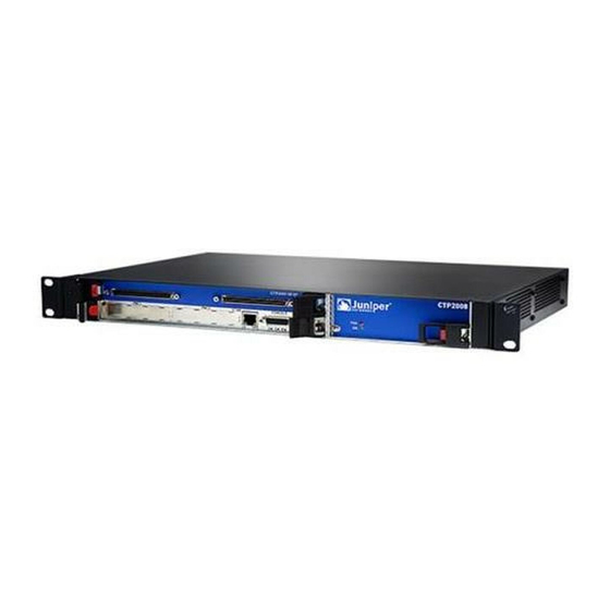
Page 10: Ctp2008 Platform
RS232 CTP2008 Platform The Juniper Networks CTP2008 Circuit to Packet platform is a 3-U high, full-rack wide chassis designed for tabletop or shelf installation. It can also be installed in a rack with the supplied rack-mounting kit. The CTP2008 platform has one removable interface module and one removable processor module, and is available in both AC-powered and DC-powered versions. - Page 11 DC version. There is no power redundancy for the AC version and the DC version. There are no power switches on CTP2000 Series DC models, so a readily accessible disconnect device must be provided as part of the electrical installation of the unit. We recommend the 22-AWG wire for DC power terminals.
-
Page 12: Ctp2024 Platform
CTP2056 Platform | 7 CTP2024 Platform The Juniper Networks CTP2024 Circuit to Packet platform can have up to three removable interface modules and one removable processor module, and is available in both AC-powered and DC-powered versions. It has a removable fan tray, and airflow is side-to-side. - Page 13 There are no power switches on CTP2000 Series DC models, so a readily accessible disconnect device must be provided as part of the electrical installation of the unit. We recommend the 22-AWG wire for DC power terminals.
-
Page 14: Ctp2056 Platform
CTP2056 Platform | 7 CTP2056 Platform The Juniper Networks CTP2056 Circuit to Packet platform can have up to seven removable interface modules and one removable processor module, and is available in both AC-powered and DC-powered versions. It has a removable fan tray, and airflow is side-to-side. - Page 15 There are no power switches on CTP2000 Series DC models, so a readily accessible disconnect device must be provided as part of the electrical installation of the unit. We recommend the 22-AWG wire for...
- Page 16 Ethernet connection—Provides the 1-Gbps Ethernet connection to the IP network by means of a local Ethernet switch or router. Console connection—Provides an asynchronous tty connection for locally configuring the CTP Series device. On the PP310 and PP332 processors, you can connect a console directly to the COM2 port (which is an RJ-45 type connector) found on the RTM panel.
- Page 17 Figure 10: CTP2056 Platform Containing the PP332 Processor (DC Version, Rear View) RELATED DOCUMENTATION CTP2008 Platform | 3 CTP2024 Platform | 5...
-
Page 18: Ctp2000 Series Interface Modules
CTP2000 Clock Interface Modules | 27 CTP2000 PMC Module | 30 CTP2000 Serial Interface Modules The Juniper Networks CTP2008, CTP2024, and CTP2056 Circuit to Packet platforms have up to one, three, and seven serial interface modules, respectively. The interface modules are interchangeable between the platforms. -
Page 19: Ctp2000 Multiservice Interface Module
CTP2000 2W-FXS and 2W-FXO Interface Modules | 20 CTP2000 8P-IRIG Interface Module | 26 CTP2000 Multiservice Interface Module The Juniper Networks CTP2000 Circuit to Packet platform optionally includes an 8-port Serial Multiservice Interface module (CTP2000-IM-8p-MS) as shown in Figure 12 on page... -
Page 20: Ctp2000 T1/E1 Interface Module
Serial Multiservice Interface Module Overview CTP2000 T1/E1 Interface Module The CTP2000 Series T1/E1 interface module has RJ-48 ports numbered 0–7 left to right. It provides a configurable eight-port E1 (2.048 MHz) or T1 (1.544 MHz) interface with AMI or B8ZS encoding. (See Figure 13 on page 13.) You can use the eight port T1/E1 interface module to interconnect digital voice... -
Page 21: Ctp2000 4We&M Interface Module
CTP2000 2W-FXS and 2W-FXO Interface Modules | 20 CTP2000 4WE&M Interface Module The CTP2000 Series 4WE&M interface module has eight 4-wire E&M ports. It is used with voice compression (VCOMP) bundles in CTP2000 models and can be used only with a CTP2000 compression module. - Page 22 NOTE: You can use the eight port T1/E1 interface module to interconnect digital voice applications with CESoPSN bundles. Four-wire audio interfaces with E and M signaling interfaces (4WE&M) are commonly used as trunks between a central office (CO) and a private branch exchange (PBX). E and M is a type of supervisory line signaling that uses separate leads, called the "E"...
- Page 23 Figure 17: Jumper Locations on the RTM E&M type config jumpers Unused dual RJ-45 Figure 18: Jumper Positions for Signaling Types Type I Type II Pin 1 Type V NOTE: Jumper JP17 must be in Position 1-2 (see Table 1 on page 16) if any ports are set for Type II signaling.
- Page 24 Table 1: Jumper Positions for Configuring Port Signaling Type (continued) Jumper Signaling Type I Signaling Type II Signaling Type V Position 2-3 Position 2-3 Position 1-2 Port 1 Position 1-2 Position 2-3 Position 1-2 JP10 Position 2-3 Position 2-3 Position 1-2 Port 2 Position 1-2 Position 2-3...
-
Page 25: Supervisory Signaling
Table 2 on page 18 for signal definitions. See “CTP2000 4WE&M Interface Connector Pinouts” on page 45 for the connector A and B pinouts. Table 2: Signal Definitions Signal Name Signal Definition Port x T, R Audio transmit pair, 600 Ohm Port x T1, R1 Audio receive pair, 600 Ohm Port x E... - Page 26 Figure 19: Analog 4WE&M Signaling Types Type I uses two leads—the E and M leads—for signaling. During inactivity, the E lead is open and the M-lead is connected to ground. The CTP device connects the E lead to a grounding point to signal off-hook, and the PBX connects the M lead to the battery (–48 V) to signal off-hook.
-
Page 27: Ctp2000 2W-Fxs And 2W-Fxo Interface Modules
Type V uses two leads, the E and M leads, for signaling. During inactivity, both the E and M leads are open. The CTP device signals off-hook by connecting the E lead to ground. The trunk circuit signals off-hook by connecting the M lead to ground. - Page 28 the FXS interface. An FXO interface is a two-wire interface; the leads are called the tip (T) and the ring (R). You can interconnect the following voice applications with CESoPSN bundles: Analog 4WE&M voice applications using the 4WE&M interface module Digital voice applications using the T1/E1 interface module Both interface modules consist of a front module and an RTM.
-
Page 29: Required Cables And Pinouts
Required Cables and Pinouts The CTP2000 2W-FXS and 2W-FXO interface modules require the use of double-shielded cables (copper braid plus aluminum mylar foil) to ensure EMI compliance. See “CTP2000 FXS and FXO Interface Module Cables and Pinouts” on page 48 for particulars about cable pinouts. -
Page 30: Analog Fxs/Fxo Ground-Start Signaling
Note that loop-start circuits are not sensitive to tip/ring reversal. For example, the tip on the FXO device may be connected to either the tip or ring on the FXS. Analog FXS/FXO Ground-Start Signaling Ground-start signaling is used to minimize the potential for glare. Unlike loop-start circuits, ground-start circuits operate correctly only when the FXO tip is connected to the FXS tip and the FXO ring is connected to the FXS ring. -
Page 31: Digital Fxs/Fxo Ground-Start Signaling
to the B bit. Because the signaling is bidirectional, the FXS side must echo the B bit when sending out the A bit. The same logic applies to the FXO interface. The FXO device goes on/off-hook. It must respond to the A bit, going off-hook when A transitions from 0 to 1, and going on-hook when A goes from 1 to 0. - Page 32 Table 4: Ground-Start Signaling at FXO Interface for Call Initiated by the FXO Interface (continued) Signaling Bits to FXO Signaling Bits from FXO FXO goes off-hook (closes loop) Duration of call Table 5: Ground-Start Signaling at FXO Interface for Call Initiated by the FXS Interface Signaling Bits to FXO Signaling Bits from FXO Idle (before call starts)
-
Page 33: Ctp2000 8P-Irig Interface Module
Table 7: Ground-Start Signaling at FXS Interface for Call Initiated by the FXO Interface (continued) Signaling Bits to FXS Signaling Bits from FXS FXO goes off-hook (closes loop) Duration of call RELATED DOCUMENTATION CTP2000 Serial Interface Modules | 11 CTP2000 T1/E1 Interface Module | 13 CTP2000 Compression Module | 13 CTP2000 4WE&M Interface Module | 14 CTP2000 8P-IRIG Interface Module | 26... -
Page 34: Ctp2000 Clock Interface Modules
Figure 24: CTP2000 8P-IRIG Interface Module CTP2000 IM 8P IRIG CTP200 0 IM 8P IRIG RELATED DOCUMENTATION CTP2000 Serial Interface Modules | 11 CTP2000 T1/E1 Interface Module | 13 CTP2000 Compression Module | 13 CTP2000 4WE&M Interface Module | 14 CTP2000 2W-FXS and 2W-FXO Interface Modules | 20 CTP2000 Clock Interface Modules Clock interface modules provide clock distribution between modules when the backplane is in use by voice... - Page 35 Figure 26: Clock Spoke Module The clock main module accepts an external clock reference and distributes it to the spoke module using a twisted pair cable. Each nonvoice card receives the clock on the first RJ-45 and sends it to the front module.
-
Page 36: External Reference Clock
NOTE: BITS input is a T1/E1 line interface unit (LIU), with AMI (alternate mark inversion) encoding enabled and B8ZS/HDB3 (Zero Suppression) disabled. The equalization is set for a 0-133 feet cable. An internal 100 ohm termination is present, although it might need to be externally augmented based on the type of cabling used. -
Page 37: Installation Notes For Clock Interface Modules
Installation Notes for Clock Interface Modules Main modules and spoke modules are not hot-swappable. Nonvoice modules and voice modules can be installed in any slot. Main clock RTMs must be installed in slot 0 behind either a serial module or a T1/E1 module. Spoke RTMs must be installed behind serial modules and the lowest-numbered T1/E1 slot. - Page 38 CTP-SFP-1GE-SX: Small form -factor pluggable 1000BASE- SX Gigabit Ethernet optic module CTP-SFP-1GE-LX: Small form-factor pluggable 1000BASE-LX Gigabit Ethernet optic module For information about how to install a PMC on CTP2000 Platforms, see “Installing a PMC on CTP2000 Platforms” on page Figure 28: CTP2000 PMC Module Location RELATED DOCUMENTATION CTP2000 Serial Interface Modules | 11...
-
Page 39: Planning
PART Planning System Specifications | 33 Planning and Preparing the Site | 40 Equipment Rack Requirements | 42 Cable and Pinout Specifications | 45... -
Page 40: System Specifications
CHAPTER 3 System Specifications IN THIS CHAPTER CTP2008 Platform Specifications and Certification | 33 CTP2024 Platform Specifications and Certification | 35 CTP2056 Platform Specifications and Certification | 38 CTP2008 Platform Specifications and Certification Table 8: CTP2008 Platform Specifications Category Specification Weight Chassis only 16 lb (7.25 kg) - Page 41 Table 8: CTP2008 Platform Specifications (continued) Category Specification Power 144 W Redundancy (input power) 2 independent line feeds AC Input Power required 100–240 VAC AC line frequency 50–60 Hz Nominal current (115V amps) Power 200 W Space Requirements 3 ft. (90 cm) behind device or rack. Do not block air vents on the front or back of the device.
-
Page 42: Ctp2024 Platform Specifications And Certification
Table 8: CTP2008 Platform Specifications (continued) Category Specification Electromagnetic Emissions Agency AS/NZS CISPR 22:2004 Certification EMC Directive (89/336/EEC) EN 300 132–2 (Narrowband and Wideband) EN55022 Class A (CISPR-22 Class A) EN55024, Annex C for WAN Equipment Performance Criteria A, B, and EN 61000-4-2, EN 61000-4-3, EN 61000-4-4, EN 61000-4-6 ETSI 300-386, Telecommunication Network Equipment;... - Page 43 Table 9: CTP2024 Platform Specifications (continued) Category Specification Environmental Requirements Ambient operating temperature 32° to 104° F (0° to 40° C) Ambient operating humidity 5% to 90% (noncondensing) DC Input Voltage –40 to –72 VDC Current 3A @ –48 VDC Power 144 W Redundancy (input power)
- Page 44 Table 9: CTP2024 Platform Specifications (continued) Category Specification Safety Agency Certification AS/NZS 60950:2000 Safety of Information Technology Equipment CAN/CSA-C22.2, No. 60950-1–03, First Edition, Information Technology Equipment - Safety - Part 1: General Requirements EN60825-1, Safety of Laser Products - Part 1: Equipment Class, Requirements, and User's Guide (2001) EN 60950-1:2001, First Edition, Information Technology Equipment - Safety - Part 1: General Requirements...
-
Page 45: Ctp2056 Platform Specifications And Certification
CTP2056 Platform Specifications and Certification Table 10: CTP2056 Platform Specifications Category Specification Weight Chassis only 27 lb (12.25 kg) Dimensions Chassis only 7.0 in. (17.8 cm) high 17.25 in. (43.81 cm) wide 11.25 in. (28.57 cm) deep Environmental Requirements Ambient operating temperature 32°... - Page 46 Table 10: CTP2056 Platform Specifications (continued) Category Specification Airflow Air intake occurs from the front of the device. Air is exhausted out the back of the device. Safety Agency Certification AS/NZS 60950:2000 Safety of Information Technology Equipment CAN/CSA-C22.2, No. 60950-1–03, First Edition, Information Technology Equipment - Safety - Part 1: General Requirements EN60825-1, Safety of Laser Products - Part 1: Equipment Class, Requirements, and User's Guide (2001)
-
Page 47: Planning And Preparing The Site
CTP2000 Environmental Requirements | 40 Before You Install a CTP Platform Before you install a Juniper Networks CTP Circuit to Packet platform: Verify that the electrical supply meets all power requirements. See the system specifications for the applicable CTP model. - Page 48 and the installed equipment. Place the device in a location with sufficient access to power and network cables. Like other network devices, the device generates a significant amount of heat. You must provide a balanced environment so that the device performs properly and safely. See the individual system specifications for acceptable ranges of temperature and humidity.
-
Page 49: Equipment Rack Requirements
CHAPTER 5 Equipment Rack Requirements IN THIS CHAPTER CTP2000 Rack Requirements | 42 CTP2000 Mechanical Requirements | 42 CTP2000 Space Requirements | 43 CTP2000 Rack Installation | 43 CTP Cabling Recommendations | 44 CTP2000 Rack Requirements When allocating equipment rack space, consider the following: Type of equipment racks recommended for the system Number of equipment racks required to hold your current system configuration Future expansion... -
Page 50: Ctp2000 Space Requirements
EIA-310-D document. A fully loaded rack with three CTP2056 systems must structurally support at least 100 lb (46 kg). An optional mounting kit is available for midchassis mounting. Contact your Juniper Networks sales representative for more information. RELATED DOCUMENTATION... -
Page 51: Ctp Cabling Recommendations
Racks are installed and electrically grounded according to manufacturer instructions. Equipment racks are anchored to the floor and, when possible, anchored to the ceiling as well. Equipment rack installations comply with applicable local, state, and national codes. RELATED DOCUMENTATION CTP2000 Mechanical Requirements | 42 CTP2000 Rack Requirements | 42 CTP2000 Space Requirements | 43 Special Guidelines for Installing CTP2056 Chassis in a Rack | 91... -
Page 52: Cable And Pinout Specifications
CTP2000 FXS and FXO Interface Module Cables and Pinouts | 48 T1/E1 Interface Module Pinouts | 51 CTP2000 Serial Interface Module Pinouts | 52 CTP2000 Series Console Cable Pinouts | 63 CTP Fast Ethernet and Power Cables | 68 Terminal Block and Circuit Breaker Specifications | 69 CTP2000 4WE&M Interface Connector Pinouts... -
Page 53: Ctp2000 4We&M Connector B Pinouts
Table 11: CTP2000 4WE&M RTM Pinouts–Connector A (continued) Connector A Signal Signal Port 0 R1 Port 0 T1 Port 0 SG Port 0 E Port 0 SB Port 0 M Port 1 R Port 1 T Port 2 R1 Port 1 T1 Port 2 SG Port 1 E Port 2 SB... - Page 54 Table 12: CTP2000 4WE&M RTM Pinouts–Connector B Connector B Signal Signal Port 4 R Port 4 T Port 4 R1 Port 4 T1 Port 4 SG Port 4 E Port 4 SB Port 4 M Port 5 R Port 5 T Port 5 R1 Port 5 T1 Port 5 SG...
-
Page 55: Ctp2000 Fxs And Fxo Interface Module Cables And Pinouts
CTP2000 FXS and FXO Interface Module Cables and Pinouts | 48 CTP2000 Series Console Cable Pinouts | 63 CTP2000 FXS and FXO Interface Module Cables and Pinouts IN THIS SECTION Required Cables | 48 RTM Pinout Locations | 48 FXS Connector Pinouts | 49... -
Page 56: Fxs Connector Pinouts
Figure 29: RTM Pinouts for CTP2000 2W-FXS and 2W-FXO Interface Modules RJ21x FXS Connector Pinouts The RTM for the CTP2000 2W-FXS interface module uses a RJ-21 25-pair Telco connector labeled A. The A connector has 24 FXS ports. FXS R is connected to FXO T; FXS T is connected to FXO T. Table 13 on page 49 lists the RTM pinouts for the FXS module. -
Page 57: Fxo Connector Pinouts
Table 13: CTP2000 FXS Connector Pinouts on the RTM (continued) Signal Signal Port 8 R Port 8 T Port 9 R Port 9 T Port 10 R Port 10 T Port 11 R Port 11 T Port 12 R Port 12 T Port 13 R Port 13 T Port 14 R... -
Page 58: T1/E1 Interface Module Pinouts
RELATED DOCUMENTATION CTP2000 2W-FXS and 2W-FXO Interface Modules | 20 CTP2000 4WE&M Interface Connector Pinouts | 45 CTP2000 Series Console Cable Pinouts | 63 CTP Fast Ethernet and Power Cables | 68 T1/E1 Interface Module Pinouts Table 15 on page 52... -
Page 59: Ctp2000 Serial Interface Module Pinouts
CTP2000 FXS and FXO Interface Module Cables and Pinouts | 48 CTP2000 Series Console Cable Pinouts | 63 Cabling a CTP2000 T1/E1 Interface Module | 111 CTP2000 Serial Interface Module Pinouts Figure 30 on page 53 displays the serial DCE/DTE cable pin configurations for CTP2000 series devices. - Page 60 Figure 30: CTP2000 Serial DCE/DTE Cable Pin Configurations DB-25 shell DB-25 connector — — Thumb screw — Table 16 on page 53 lists the CTP2000 serial DCE cable pinouts. Table 16: CTP2000 Serial DCE Cable Pinouts Cable J1 SCSI DB-25 P0-2 P0-14 P0-20...
- Page 61 Table 16: CTP2000 Serial DCE Cable Pinouts (continued) Cable J1 SCSI DB-25 P0-12 P0-16 P0-3 P0-22 P0-6 P0-13 P0-5 P0-8 P0-25 P0-9 P0-10 P0-18 P0-17 P0-24 P0-11 P0-7 P0-21 P0-1 P1-14 P1-2 P1-23...
- Page 62 Table 16: CTP2000 Serial DCE Cable Pinouts (continued) Cable J1 SCSI DB-25 P1-20 P1-19 P1-4 P1-12 P1-15 P1-3 P1-16 P1-6 P1-22 P1-5 P1-13 P1-25 P1-8 P1-10 P1-9 P1-17 P1-18 P1-11 P1-24 P1-21 P1-7...
- Page 63 Table 16: CTP2000 Serial DCE Cable Pinouts (continued) Cable J1 SCSI DB-25 P1-1 P2-2 P2-14 P2-20 P2-23 P2-4 P2-19 P2-15 P2-12 P2-16 P2-3 P2-22 P2-6 P2-13 P2-5 P2-8 P2-25 P2-9 P2-10 P2-18 P2-17...
- Page 64 Table 16: CTP2000 Serial DCE Cable Pinouts (continued) Cable J1 SCSI DB-25 P2-24 P2-11 P2-7 P2-21 P2-1 P3-14 P3-2 P3-23 P3-20 P3-19 P3-4 P3-12 P3-15 P3-3 P3-16 P3-6 P3-22 P3-5 P3-13 P3-25 P3-8...
- Page 65 Table 16: CTP2000 Serial DCE Cable Pinouts (continued) Cable J1 SCSI DB-25 P3-10 P3-9 P3-17 P3-18 P3-11 P3-24 P3-21 P3-7 P3-1 Table 17 on page 58 lists the CTP2000 serial DTE cable pinouts. Table 17: CTP2000 Serial DTE Cable Pinouts Cable J1 SCSI DB-25...
- Page 66 Table 17: CTP2000 Serial DTE Cable Pinouts (continued) Cable J1 SCSI DB-25 P0-2 P0-23 P0-20 P0-19 P0-4 P0-8 P0-21 P0-11 P0-10 P0-18 P0-24 P0-17 P0-9 P0-7 P0-25 P0-1 P1-16 P1-3 P1-22 P1-6 P1-13...
- Page 67 Table 17: CTP2000 Serial DTE Cable Pinouts (continued) Cable J1 SCSI DB-25 P1-5 P1-12 P1-15 P1-2 P1-14 P1-20 P1-23 P1-4 P1-19 P1-21 P1-8 P1-10 P1-11 P1-24 P1-18 P1-9 P1-17 P1-25 P1-7 P1-1 P2-3...
- Page 68 Table 17: CTP2000 Serial DTE Cable Pinouts (continued) Cable J1 SCSI DB-25 P2-16 P2-6 P2-22 P2-5 P2-13 P2-15 P2-12 P2-14 P2-2 P2-23 P2-20 P2-19 P2-4 P2-8 P2-21 P2-11 P2-10 P2-18 P2-24 P2-17 P2-9...
- Page 69 Table 17: CTP2000 Serial DTE Cable Pinouts (continued) Cable J1 SCSI DB-25 P2-7 P2-25 P2-1 P3-16 P3-3 P3-22 P3-6 P3-13 P3-5 P3-12 P3-15 P3-2 P3-14 P3-20 P3-23 P3-4 P3-19 P3-21 P3-8 P3-10 P3-11...
-
Page 70: Ctp2000 Series Console Cable Pinouts
The console port CTP2008, CTP2024, and CTP2056 devices with the new PP833 processor uses a USB-type connector located on the right of the PP833 faceplate labelled “RS-232”. CTP2000 series devices with the PP310 and PP332 processors use an RJ-45 connected to the COM2 port. This cable must be connected during the first boot process. - Page 71 Stop bits: 1 Flow control: Xon/Xoff Parity: none Figure 31: CTP2000 Series Console Cable Pin Configurations for PP310 and PP332 Processors Table 18 on page 64 Table 19 on page 64 list console cable pinouts for CTP2000 Series devices based on the pin configurations.
- Page 72 Table 19: CTP2000 Series Console Cable (p/n 720-071594) Pinouts for the PP833 Processor (continued) USB Console Connector DB-9 Male 4 GND 5 GND Table 20: DB9-to-RJ45 Adapter (p/n 450-071855) Pinouts for Connecting PP833 Processor with Console RJ-45 DB-9 3 TXD...
- Page 73 “p/n 450-071855”, the available RJ-45 console pinout will be similar to the CTP150 console port (and other Juniper routers). To connect the PP833 processor with the DB-9 male serial port of a PC, additionally connect a straight RJ-45 cable with the DB-9 adapter from the bag labelled “p/n 720-056657”.
- Page 74 Adapter from the bag labelled 720-056657 — — Cable 720-071594 RJ-45 male end of user’s console cable — — DB-9 male end of 720-071594 User’s cable that connects to the console on a — — CTP150 or other Juniper product...
-
Page 75: Ctp Fast Ethernet And Power Cables
Figure 34: Connecting the PP833 Processor with the PC DB-9M Serial Console PP833 front panel RJ-45 male end — — Cable 720-071594 Straight RJ-45 cable — — DB-9 male end of 720-071594 RJ-45 male end — — DB-9 female end of adapter from the bag labelled Adapter from the bag labelled 720-014126 —... -
Page 76: Fast Ethernet Cables
Terminal Block and Circuit Breaker Specifications Table 23 on page 69 lists the electrical specifications for the terminal block (see Figure 35 on page located on the back of the CTP2000 Series DC chassis. Table 23: Terminal Block Electrical Specifications Category Specification... - Page 77 (33.35 mm) 1.738 in. (44.17 mm) Table 24 on page 70 summarizes the electrical specification for the circuit breaker that is attached on the back of the CTP2000 Series DC chassis. Table 24: Circuit Breaker Specification Platform Specification CTP2008-DC CTP2024-DC...
- Page 78 PART Safety General Safety Guidelines and Warnings | 72 Module Installation Safety Guidelines and Warnings | 74 Hardware Compliance | 76...
-
Page 79: General Safety Guidelines And Warnings
CHAPTER 7 General Safety Guidelines and Warnings IN THIS CHAPTER CTP Safety Guidelines and Warnings | 72 CTP Safety Guidelines and Warnings For your safety, before installing the device, review all safety warnings in this section. WARNING: The recommended maximum ambient temperature is 40˚°C (104° F). For safe operation take into consideration the internal temperature within the rack. - Page 80 WARNING: Do not work on the device or connect or disconnect cables during lightning activity. WARNING: Be sure that circuit breakers for the power source are in the OFF position before attaching power cables. WARNING: Before servicing the device, turn off the power. WARNING: Remove jewelry (including rings, necklaces, and watches) before working on equipment that is connected to power lines.
-
Page 81: Module Installation Safety Guidelines And Warnings
Doing so can cause electric shock and serious burns. WARNING: Never attempt to repair parts of modules yourself. Only trained customer service personnel are authorized to service parts. Call Juniper Networks Customer Service to make arrangements to return defective modules for repair. - Page 82 RELATED DOCUMENTATION Required Tools and Safety Items for Installing CTP150 Modules Federal Communications Commission (FCC) Statement | 78 FCC Requirements for Consumer Products | 78 Food and Drug Administration, Center for Devices and Radiological Health | 79 Compliance with Canadian Regulations | 79...
-
Page 83: Hardware Compliance
FCC Requirements for Consumer Products | 78 Food and Drug Administration, Center for Devices and Radiological Health | 79 Compliance with Canadian Regulations | 79 Statements of Volatility for Juniper Network Devices | 82 Declaration of Conformity for CTP2000 Platforms Figure 36 on page 77... - Page 84 Figure 36: CTP2000 Declaration of Conformity RELATED DOCUMENTATION CTP2008 Platform Specifications and Certification | 33 CTP2024 Platform Specifications and Certification | 35 CTP2056 Platform Specifications and Certification | 38...
-
Page 85: Federal Communications Commission (Fcc) Statement
Federal Communications Commission (FCC) Statement This equipment has been tested and found to comply with the limits for a Class A digital device, pursuant to Part 15 of the FCC Rules. These limits are designed to provide reasonable protection against harmful interference when the equipment is operated in a commercial environment. -
Page 86: Food And Drug Administration, Center For Devices And Radiological Health
RELATED DOCUMENTATION Federal Communications Commission (FCC) Statement | 78 Food and Drug Administration, Center for Devices and Radiological Health | 79 Compliance with Canadian Regulations | 79 Food and Drug Administration, Center for Devices and Radiological Health This equipment complies with 21 CFR 1040.10 and 1040.11 for the safe use of lasers. RELATED DOCUMENTATION Federal Communications Commission (FCC) Statement | 78 FCC Requirements for Consumer Products | 78... -
Page 87: Industry Canada Notice Cs-03
Industry Canada Notice CS-03 The Industry Canada label identifies certified equipment. This certification means that the equipment meets certain telecommunications network protective, operation and safety requirements as prescribed in the appropriate Terminal Equipment Technical Requirements document(s). The Department does not guarantee that the equipment will operate to the user's satisfaction. -
Page 88: Canadian Department Of Communications Explanatory Notes
Avis: Veuillez prendre note que pour tout appareillage supportant des lignes de type “loopstart,” l'indice d'équivalence de la sonnerie (IES) assigné à chaque dispositif terminal indique le nombre maximal de terminaux qui peuvent être raccordés à une interface. La terminaison d'une interface téléphonique peut consister en une combinaison de quelques dispositifs, à... -
Page 89: Statements Of Volatility For Juniper Network Devices
Statements of Volatility for Juniper Network Devices A statement of volatility (SoV)—sometimes known as letter of volatility (LoV)—identifies the volatile and non-volatile storage components in Juniper Networks devices, and describes how to remove non-volatile storage components from the device. NOTE: Individual FRUs do not have separate SoV or LoV documents. - Page 90 CTP Series: CTP150 CTP2000 EX Series: EX2200 and EX2200-C EX2300-24P, EX2300-24T, and EX2300-24T-DC EX2300-48P and EX2300-48T EX2300-C EX3300 EX3400-24P, EX3400-24T, EX3400-24T-DC EX3400-48P, EX3400-48T, EX3400-48T-AFI EX4200 EX4300 EX4300-48MP EX4500 EX4550 EX4600 EX8200 XRE200 External Routing Engine LN Series: LN1000–CC MX Series: M7i Compact Forwarding Engine Board (CFEB) M40e and M10i M320...
- Page 91 MX10003 RE-A-2000 Route Engine RE-S-X6-64G Routing Engine QFX Series: QFX3008-I QFX3100 QFX3500 QFX3600 QFX5100-24Q QFX5100-48S QFX5100-48T QFX5110-32Q QFX5110-48S QFX5200 QFX5200-32C QFX10008 and QFX10016 SRX Series: SRX100 SRX110 SRX210B SRX210H-POE SRX210H-P-MGW SRX220 SRX240H SRX240H-POE SRX300 SRX320 SRX340 and SRX345 SRX550 SRX650...
- Page 92 SRX1400 SRX1500 SRX3400 and SRX3600 SRX5400, SRX5600, and SRX5800 SRX-MP-1SERIAL SSG-520M T Series: RE-A-2000 Route Engine...
-
Page 93: Installation
PART Installation Unpacking and Inspecting the CTP Platform | 87 Installing the Chassis | 90 Installing Modules | 93 Installing and Removing SFPs in a CTP Module | 102 Upgrading Components for Memory Upgrades | 106 Cabling | 108 Powering On | 115... -
Page 94: Unpacking And Inspecting The Ctp Platform
Unpacking the CTP Device | 87 Inspecting Platform Components and Accessories | 88 If You Detect or Suspect Damage | 89 Contacting Juniper Networks | 89 Before You Unpack the CTP Platform Before you begin unpacking the device, be sure you have the following tools: No. -
Page 95: Inspecting Platform Components And Accessories
Before You Unpack the CTP Platform | 87 Inspecting Platform Components and Accessories | 88 If You Detect or Suspect Damage | 89 Contacting Juniper Networks | 89 Inspecting Platform Components and Accessories After you remove the equipment from the shipping containers: Confirm the contents of each container. -
Page 96: If You Detect Or Suspect Damage
Inspecting Platform Components and Accessories | 88 Contacting Juniper Networks | 89 Contacting Juniper Networks Please contact Juniper Networks at 1-888-314-JTAC (from the United States, Canada, or Mexico) or 1-408-745-9500 (from elsewhere), or contact your sales representative if you have any questions or concerns. See “Contacting Customer Support”... -
Page 97: Installing The Chassis
CHAPTER 11 Installing the Chassis IN THIS CHAPTER Before You Install the CTP2000 Platform | 90 Installing the CTP2000 Platform in Freestanding Mode | 91 Special Guidelines for Installing CTP2056 Chassis in a Rack | 91 Installing the CTP2000 Platform in a Rack | 92 Before You Install the CTP2000 Platform Before installing the platform: Refer to the platform specifications for the particular CTP model or series. -
Page 98: Installing The Ctp2000 Platform In Freestanding Mode
Installing the CTP2000 Platform in Freestanding Mode When installing the device on a table top or in any other freestanding mode, be sure to leave enough space around the device for adequate ventilation. Position the chassis with easy access to the connections that it needs for power, local communications, and remote communications. -
Page 99: Installing The Ctp2000 Platform In A Rack
Installing the CTP2000 Platform in a Rack To install the CTP platform in a rack, you need: Phillips screwdriver Four 10-32 x 3/8 Phillips screws for each device to be installed Follow these guidelines: 1. Following your installation plan, use a tape measure and marking pen to measure and mark space on each equipment rack for each platform component. -
Page 100: Installing Modules
Installing a CTP Interface Module, Processor Module, or Clock Module | 95 Removing a CTP Interface Module, Processor Module, or Clock Module | 96 Installing or Removing a CTP2000 Series CompactFlash Card | 98 Installing a PMC on CTP2000 Platforms | 99 CTP2000 Modules Installation Overview In CTP2000 platforms, you can install interface modules in the front and rear of the device. -
Page 101: Protecting Ctp2000 Modules And Slots
Protecting CTP2000 Modules and Slots To prevent damage from electrostatic discharge, wear an antistatic wrist strap, and connect it to one of the jacks when handling components. The CTP2056 has an ESD (electrostatic discharge) grounding jack located in the rear lower-left corner of the chassis near the power switch. There are no ESD jacks on the other CTP2000 platforms, so you must use another grounding device. -
Page 102: Required Tools And Safety Items For Installing Ctp Modules
Required Tools and Safety Items for Installing CTP Modules You need the following tools to install the interface module of a CTP151 device: Phillips screwdriver ESD wrist strap or other grounding device RELATED DOCUMENTATION Safety Guidelines and Warnings for Installing CTP151 Modules Installing a CTP Interface Module, Processor Module, or Clock Module Installing a CTP Interface Module, Processor Module, or Clock Module To install a CTP module:... -
Page 103: Removing A Ctp Interface Module, Processor Module, Or Clock Module
CAUTION: If you meet strong resistance when attempting to seat the module using the ejectors, remove it from the chassis, and confirm that the slot is designed to hold the component. Also, be sure that you have aligned the left and right edges in the correct matching tracks. - Page 104 CAUTION: If you do not use the halt command before powering down the CTP device, the CompactFlash card might become corrupted. To remove a CTP module: 1. Issue the halt command. 2. Ground yourself by using an antistatic wrist strap or other device, and connect it to an ESD grounding jack, if available, or another grounding device.
-
Page 105: Installing Or Removing A Ctp2000 Series Compactflash Card
(which may be located under an installed PMC card), which prevents insertion or removal of the CompactFlash card until the PMC card is removed. On the CTP2000 series devices with the PP310 and PP332 processors, the CompactFlash card is installed on the processor rear transition module (RTM). -
Page 106: Installing A Pmc On Ctp2000 Platforms
To remove or install the CompactFlash card for the CTP2000 series with the PP310 and PP332 processors (see Figure 38 on page 99): 1. Power off the unit. 2. Remove the processor RTM by unscrewing the retaining screws and pushing the extractors outward with the latching buttons depressed. - Page 107 Figure 39: CTP2000 Platforms PMC Location To install a PMC: 1. Confirm that the device is powered off. 2. Remove the processor module by unscrewing the retaining screws and pushing the extractors outward while depressing the latching buttons. 3. If a PMC was not previously installed, a shield may have been inserted in the PMC slot of the processor’s front panel.
- Page 108 7. From the back of the processor module, use the four Phillips head screws to secure the two PMC standoff posts and PMC front assembly to the processor module. 8. Reinstall the processor. RELATED DOCUMENTATION Installing a CTP Interface Module, Processor Module, or Clock Module | 95 CTP2000 PMC Module | 30...
-
Page 109: Installing And Removing Sfps In A Ctp Module
CHAPTER 13 Installing and Removing SFPs in a CTP Module IN THIS CHAPTER Installing SFPs in a CTP2000 Module | 102 Removing SFPs in a CTP2000 Module | 104 Installing SFPs in a CTP2000 Module This section describes how to install small form-factor pluggable transceivers (SFPs) on interface modules that support these devices. - Page 110 Figure 40: Representative SFP CAUTION: Be sure to position the SFP correctly before you install it. 3. Hold the SFP so that: The connection circuitry is adjacent to the module's faceplate. The cable connectors are visible when you install the SFP. 4.
-
Page 111: Removing Sfps In A Ctp2000 Module
Removing SFPs in a CTP2000 Module This section describes how to replace small form-factor pluggable transceivers (SFPs) on interface modules that support these devices. You can replace the SFPs without disabling the interfaces or removing the module from the device. To remove an SFP: 1. - Page 112 Installing SFPs in a CTP2000 Module | 102...
-
Page 113: Upgrading Components For Memory Upgrades
Upgrading CTP2000 Series Components for Memory Upgrades | 106 Upgrading CTP2000 Series Components for Memory Upgrades Certain CTP2000 Series components need to be upgraded when RAM memory is increased, as required by certain JUNOS version updates. The affected modules and other components can be:... - Page 114 9. Go to “Cabling the CTP2000 Platform Overview” on page 108. RELATED DOCUMENTATION Removing a CTP Interface Module, Processor Module, or Clock Module | 96 Installing or Removing a CTP2000 Series CompactFlash Card | 98 CTP2000 Series Processor | 2...
-
Page 115: Cabling
CHAPTER 15 Cabling IN THIS CHAPTER Cabling the CTP2000 Platform Overview | 108 Required Tools, Wires, and Cables for the CTP2000 Platform | 109 CTP2000 Management Ports | 110 Cabling a CTP2000 T1/E1 Interface Module | 111 Cabling the CTP Platform for DC Power | 111 Cabling the CTP2000 Platform Overview Cabling the CTP platform requires the following main tasks: 1. -
Page 116: Required Tools, Wires, And Cables For The Ctp2000 Platform
CTP2000 Management Ports | 110 Cabling a CTP2000 T1/E1 Interface Module | 111 Cabling the CTP Platform for DC Power | 111 Setting Up Management Access on the CTP2000 Platform | 121 CTP2000 Console Port Setup | 122 T1/E1 Interface Module Pinouts | 51 Required Tools, Wires, and Cables for the CTP2000 Platform Cabling your device takes only a few minutes. -
Page 117: Ctp2000 Management Ports
450-071855”, the available RJ-45 console pinout will be similar to the CTP150 console port (and other Juniper routers). To connect the PP833 processor with the DB-9 male serial port of a PC, additionally connect a straight RJ-45 cable with the DB-9 adapter from the bag labelled “p/n 720-056657”. The other end of the RJ-45 cable connects to the DB-9 adapter from the bag labelled “p/n 720-014126”. -
Page 118: Cabling A Ctp2000 T1/E1 Interface Module
CTP2000 T1/E1 Interface Module | 13 Cabling the CTP Platform for DC Power After you have correctly cabled the RTM for the CTP2000 Series, you must attach grounding and electrical wires before you turn the device on. Three main tasks are involved: 1. -
Page 119: Task 1: Turning Off All Ctp Platform Power
3. Connect the power cables to the power supplies. Table 26 on page 112 identifies the cabling requirements. Table 26: CTP Power Supply Cables and Wires Needed Cable/Wire From One 18-AWG ground wire PDU ground terminal Termination ground Two 18-AWG wire leads PDU Power A –48 VDC and RTN leads Appropriate leads on power source No.1... -
Page 120: Task 3: Connecting The Power Cables To The Ctp2000 Platform
NOTE: When grounding the device, leave a service loop in the grounding cable to ensure that the grounding cable is the last cable to disconnect from the shelf if strain is placed on the electrical cables. Task 3: Connecting the Power Cables to the CTP2000 Platform WARNING: Before you begin this procedure, be sure the power source is turned off, the device is turned off, and proper grounding wires are attached. - Page 121 NOTE: To provide redundancy, do not use the same power source for Power A and Power B leads. 8. Repeat Steps 1–7 for each power supply module in your configuration. RELATED DOCUMENTATION CTP2000 Management Ports | 110 Cabling a CTP2000 T1/E1 Interface Module | 111 Required Tools, Wires, and Cables for the CTP2000 Platform | 109 Terminal Block and Circuit Breaker Specifications | 69...
-
Page 122: Powering On
CHAPTER 16 Powering On IN THIS CHAPTER Before You Power On the CTP2000 Platform | 115 Powering On the CTP2000 Platform | 116 Powering Off the CTP Platform | 119 Before You Power On the CTP2000 Platform Before powering on the device, make sure you complete the following tasks. See the appropriate sections for information about these tasks. -
Page 123: Powering On The Ctp2000 Platform
Powering On the CTP2000 Platform NOTE: In this procedure we assume that the device is already connected to a power source. If using a DC power supply, see “Cabling the CTP Platform for DC Power” on page 111. For specifications on the electrical requirements for the device, see one of the following topics: CTP2008 Platform Specifications and Certification on page 33 CTP2024 Platform Specifications and Certification on page 35 CTP2056 Platform Specifications and Certification on page 38... - Page 124 3. Default interface—From the list of available devices, such as eth0 and eth1 (or more), enter the one to be the default. 4. Hostname of the device. 5. IP address of the interface—Enter the IP address of the selected interface, or accept the loopback address (127.0.0.1) by default.
- Page 125 Ctp circuits can run over any ethernet device, default or not. A default device must be configured, other devices may be configured and enabled, or disabled. Here is a list ot the available devices and their descriptions: eth0: 10/100/1000 Copper (front) eth1: 10/100/1000 Copper (back) eth2: 1000 Fiber (left) eth3: 1000 Fiber (right)
-
Page 126: Powering Off The Ctp Platform
During initial power-on, the components of the platform run boot code, go through a series of self-diagnostic tests, and synchronize with each other. When the tests are complete, use the LEDs on each module to determine the status of the device. Observe the module LEDs on the front or rear components. -
Page 127: Configuration
PART Configuration Accessing the CTP2000 Platform | 121... -
Page 128: Accessing The Ctp2000 Platform
450-071855”, the available RJ-45 console pinout will be similar to the CTP150 console port (and other Juniper routers). To connect the PP833 processor with the DB-9 male serial port of a PC, additionally connect a straight RJ-45 cable with the DB-9 adapter from the bag labelled “p/n 720-056657”. The... -
Page 129: Ctp2000 Console Port Setup
450-071855”, the available RJ-45 console pinout will be similar to the CTP150 console port (and other Juniper routers). To connect the PP833 processor with the DB-9 male serial port of a PC, additionally connect a straight RJ-45 cable with the DB-9 adapter from the bag labelled “p/n 720-056657”. The other... -
Page 130: Using Hyperterminal With The Ctp2000 Platform
RJ-45 cable connects to the DB-9 adapter from the bag labelled “p/n 720-014126”. Then, you can connect the PC’s DB-9 male connector with the DB-9 adapter “p/n 720-014126”. “CTP2000 Series Console Cable Pinouts” on page 63 for information about the pinouts of PP310/PP332 and PP833 processor console cables, USB-to-DB9 cable, and DB9-to-RJ45 adapters. -
Page 131: Connecting Directly To The Ctp2000 Platform
Setting Up Management Access on the CTP2000 Platform | 121 CTP2000 Console Port Setup | 122 Using HyperTerminal with the CTP2000 Platform | 123 CTP2000 Platform SSH Setup | 125 Required Tools, Wires, and Cables for the CTP2000 Platform | 109 CTP2000 Series Console Cable Pinouts | 63... -
Page 132: Ctp2000 Platform Ssh Setup
CTP2000 Platform SSH Setup When you have configured an IP address for the CTP2000 device, you can run SSH from a host to access the device through its Ethernet port. To connect the Ethernet port to the network: 1. Connect an RJ-45 cable to one of the two Ethernet ports of the CTP2000 chassis. This applies to the AC and DC power versions of the platform. -
Page 133: Maintenance
PART Maintenance Maintaining Components | 127 Product Reclamation and Recycling | 131 Replacing Fan Trays | 133 Packing and Returning Hardware | 135... -
Page 134: Maintaining Components
CHAPTER 18 Maintaining Components IN THIS CHAPTER Required Tools for Maintaining the CTP Platform | 127 Storing CTP Modules and Other Components | 127 Cleaning the CTP Platform | 128 Replacing an AC Power Supply | 129 Required Tools for Maintaining the CTP Platform You need the following tools and other items to replace platform components: Flathead and Phillips screwdrivers Insulated adjustable wrench... -
Page 135: Cleaning The Ctp Platform
CAUTION: Failure to store electronic modules and components correctly can lead to damage of these items. Follow these guidelines for storing modules and other components: Store each module in a separate antistatic bag. Store other components in an antistatic plastic container. Some of these containers can accommodate several components in separate compartments. -
Page 136: Replacing An Ac Power Supply
RELATED DOCUMENTATION Required Tools for Maintaining the CTP Platform | 127 Storing CTP Modules and Other Components | 127 Replacing an AC Power Supply Before you remove a power supply, be aware of the following: The minimum number of power supplies must be present in the router at all times. To maintain proper cooling and prevent thermal shutdown of the operating power supply unit, each power supply slot must contain either a power supply or a blank panel. - Page 137 Figure 42: Replacing an AC Power Supply Ejector lever Handle Fans Compact AC power Flash drive cord inlet To install an AC power supply (see Figure 42 on page 130): 1. Move the AC input switch next to the appliance inlet on the power supply to the off (O) position. 2.
-
Page 138: Product Reclamation And Recycling
Juniper Networks provides recycling support for our equipment worldwide to comply with the WEEE Directive. For recycling information, go to https://www.juniper.net/environmental, and indicate the type of Juniper Networks equipment that you wish to dispose of and the country where it is currently located, or contact your Juniper Networks account representative. - Page 139 Products returned through our reclamation process are recycled, recovered, or disposed of in a responsible manner. Our packaging is designed to be recycled and should be handled in accordance with your local recycling policies. RELATED DOCUMENTATION Return Procedure | 135 Returning CTP Products for Repair or Replacement | 136...
-
Page 140: Replacing Fan Trays
CHAPTER 20 Replacing Fan Trays IN THIS CHAPTER Removing a CTP2000 Fan Tray | 133 Installing a CTP2000 Fan Tray | 133 Removing a CTP2000 Fan Tray To remove a fan tray: 1. With an appropriate screwdriver, loosen the captive screws located at the corners of the fan tray. WARNING: Do not place your fingers near the fans when removing the fan tray. - Page 141 2. Place the side edge of the tray housing in the fan tray compartment, and push toward the back of the chassis until the tray stops. An electrical connector on the back of the fan tray pairs with an electrical connector at the back of the shelf.
-
Page 142: Packing And Returning Hardware
1. Determine the part number and serial number of the component. For instructions, see “Locating CTP Component Serial Numbers” on page 141. 2. Obtain a Return Materials Authorization (RMA) number from the Juniper Networks Technical Assistance Center (JTAC). See “Information You Might Need to Supply to JTAC” on page 141. -
Page 143: Returning Ctp Products For Repair Or Replacement
Returning CTP Products for Repair or Replacement In the event of a hardware failure, please contact Juniper Networks to obtain a Return Material Authorization (RMA) number. This number is necessary to ensure proper tracking and handling of returned material at the factory. -
Page 144: Troubleshooting
PART Troubleshooting Troubleshooting Power Failures | 138 Contacting Customer Support | 140... -
Page 145: Troubleshooting Power Failures
2. Verify that the power supply is delivering the correct voltage, current, and wattage to the device. See the system specifications for your particular CTP Series platform. 3. If the platform still does not operate, contact the Juniper Networks Technical Assistance Center (JTAC). RELATED DOCUMENTATION... -
Page 146: Ctp Platform Shuts Down
CTP Platform Shuts Down Problem Description: Symptoms: Temperature is too high. Power is lost. Solution 1. Verify that power connections are properly attached. 2. Verify that device is receiving power. 3. Look to see whether or not the LEDs are lit. 4. -
Page 147: Contacting Customer Support
Locating CTP Component Serial Numbers | 141 Information You Might Need to Supply to JTAC | 141 Contacting Customer Support See the Juniper Networks Web site for complete customer service information: https://support.juniper.net/support/ For your convenience, we provide multiple options for requesting and receiving technical support from the Juniper Networks Technical Assistance Center (JTAC): By the Web using Juniper Networks, Inc. -
Page 148: Locating Ctp Component Serial Numbers
Locating CTP Component Serial Numbers Before contacting Juniper Networks to request a Return Materials Authorization (RMA), you must find the serial number on the chassis or component. Serial numbers are located on the modules. ID labels are usually applied near the ejector. - Page 149 Locating CTP Component Serial Numbers | 141 Returning CTP Products for Repair or Replacement | 136...