
Related Manuals for Juniper CTP150


Summary of Contents for Juniper CTP150
- Page 1 CTP150 Platform Hardware Documentation Modified: 2015-11-22 Copyright © 2015, Juniper Networks, Inc.
- Page 2 END USER LICENSE AGREEMENT The Juniper Networks product that is the subject of this technical documentation consists of (or is intended for use with) Juniper Networks software. Use of such software is subject to the terms and conditions of the End User License Agreement (“EULA”) posted at http://www.juniper.net/support/eula.html.
-
Page 3: Table Of Contents
CTP150 Multiservice Interface Module ........8... - Page 4 Installing the CTP150 Platform in a Rack ....... . 52...
- Page 5 Before You Power On the CTP150 Device ....... . 65...
- Page 6 CTP150 Platform Hardware Documentation Copyright © 2015, Juniper Networks, Inc.
- Page 7 Figure 3: CTP150 Serial Interface Module ....... . . 7...
- Page 8 CTP150 Platform Hardware Documentation viii Copyright © 2015, Juniper Networks, Inc.
- Page 9 System Specifications and Certifications ......13 Table 3: CTP150 Platform Specifications ....... . . 13 Table 4: CTP150 Platform Certifications .
- Page 10 CTP150 Platform Hardware Documentation Copyright © 2015, Juniper Networks, Inc.
-
Page 11: About The Documentation
® To obtain the most current version of all Juniper Networks technical documentation, see the product documentation page on the Juniper Networks website at http://www.juniper.net/techpubs/ If the information in the latest release notes differs from the information in the documentation, follow the product Release Notes. -
Page 12: Table 1: Notice Icons
RFC 1997, BGP Communities Attribute Italic text like this Represents variables (options for which Configure the machine’s domain name: you substitute a value) in commands or [edit] configuration statements. root@# set system domain-name domain-name Copyright © 2015, Juniper Networks, Inc. -
Page 13: Documentation Feedback
We encourage you to provide feedback, comments, and suggestions so that we can improve the documentation. You can provide feedback by using either of the following methods: Online feedback rating system—On any page at the Juniper Networks Technical Documentation site at , simply click the http://www.juniper.net/techpubs/index.html... -
Page 14: Requesting Technical Support
7 days a week, 365 days a year. Self-Help Online Tools and Resources For quick and easy problem resolution, Juniper Networks has designed an online self-service portal called the Customer Support Center (CSC) that provides you with the following features: Find CSC offerings: http://www.juniper.net/customers/support/... - Page 15 About the Documentation For international or direct-dial options in countries without toll-free numbers, see http://www.juniper.net/support/requesting-support.html Copyright © 2015, Juniper Networks, Inc.
- Page 16 CTP150 Platform Hardware Documentation Copyright © 2015, Juniper Networks, Inc.
-
Page 17: Overview
PART 1 Overview CTP150 Platform Overview on page 3 CTP150 Interface Modules on page 7 Copyright © 2015, Juniper Networks, Inc. - Page 18 CTP150 Platform Hardware Documentation Copyright © 2015, Juniper Networks, Inc.
-
Page 19: Ctp150 Platform Overview
CTP devices and circuits in the network. CTP150 Platform Overview The Juniper Networks CTP150 Circuit to Packet platform is a 1-U high, full-rack wide chassis designed for tabletop or shelf installation. It can also be installed in a rack with the supplied rack-mounting kit. -
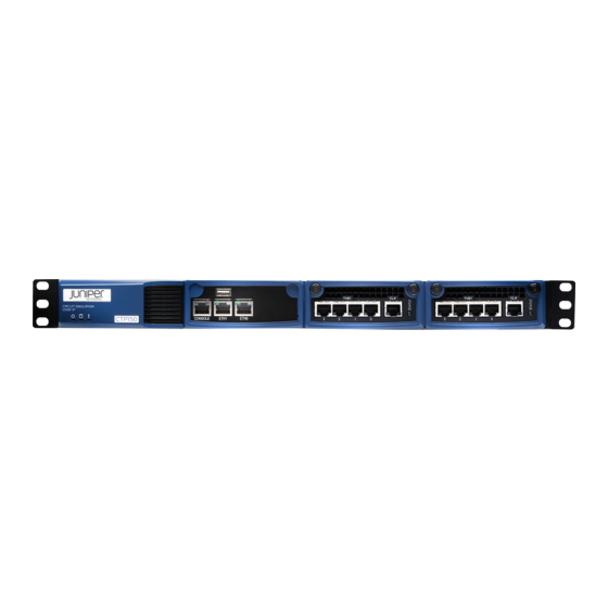
Page 20: Figure 1: Ctp150 Chassis (Front View)
Figure 2 on page Removable CompactFlash drive—The device must be powered off when you insert or remove the CompactFlash card. The CTP150 platform does not provide a hard drive, nor is it required. Removable AC power supply—Power input using a standard IEC power cord. -
Page 21: Figure 2: Ctp150 Chassis (Rear View)
Chapter 1: CTP150 Platform Overview Figure 2: CTP150 Chassis (Rear View) Ejector lever Handle Fans Compact AC power Flash drive cord inlet Related Introducing CTP Platforms on page 3 Documentation Copyright © 2015, Juniper Networks, Inc. - Page 22 CTP150 Platform Hardware Documentation Copyright © 2015, Juniper Networks, Inc.
-
Page 23: Ctp150 Interface Modules
The Juniper Networks CTP150 Circuit to Packet platform optionally includes a replaceable CTP150–IM-SER serial interface module that can be paired with another module of the same type or a T1/E1 interface module. The serial interface module also has the option of supporting two multiservice daughter cards for 4-KHz or high quality analog audio, or interrange instrumentation group (IRIG) signals. -
Page 24: Ctp150 Multiservice Interface Module
CTP150 T1/E1 Interface Module on page 9 CTP150 Multiservice Interface Module The Juniper Networks CTP150 Circuit to Packet platform optionally includes a Serial Multiservice Interface module CTP150-IM-SER-MS. The module provides 4-KHz or high quality analog audio, or interrange instrumentation group (IRIG) signals. -
Page 25: Ctp150 T1/E1 Interface Module
Serial Multiservice Interface Module Overview CTP150 T1/E1 Interface Module The Juniper Networks CTP150 Circuit to Packet platform optionally includes a replaceable CTP150-IM-4P-T1E1 interface module that can be paired with another module of the same type or a serial interface module. -
Page 26: Ctp150 Clock Module
Clock interface modules provide clock distribution between modules when the backplane is in use by voice applications. For the CTP150 model, the serial and T1/E1 interfaces each have a clock port, although only one port needs to be used for both interfaces. One port is of the HD-26 connector type, and the other is of the RJ-45 connector type. -
Page 27: Planning
PART 2 Planning System Specifications and Certifications on page 13 Planning and Preparing the Site on page 17 Equipment Rack Requirements on page 19 Cable and Pinout Specifications on page 23 Copyright © 2015, Juniper Networks, Inc. - Page 28 CTP150 Platform Hardware Documentation Copyright © 2015, Juniper Networks, Inc.
-
Page 29: System Specifications And Certifications
CHAPTER 3 System Specifications and Certifications CTP150 Platform Specifications on page 13 CTP150 Platform Certifications on page 15 CTP150 Platform Specifications Table 3: CTP150 Platform Specifications Category Specification Weight Chassis only 14.5 lb (6.6 kg) Dimensions Chassis only 1.73 in. (4.4 cm) high 17.24 in. - Page 30 CTP150 Platform Hardware Documentation Table 3: CTP150 Platform Specifications (continued) Category Specification Nominal current (115V amps) <1.0 Power 100 W Space Requirements 3 ft. (90 cm) behind device or rack. Do not block air vents on the front or back of the device.
-
Page 31: Ctp150 Platform Certifications
Chapter 3: System Specifications and Certifications CTP150 Platform Certifications Table 4: CTP150 Platform Certifications Category Specification Safety Agency Certification AS/NZS 60950.1-2003 Safety of Information Technology Equipment CAN/CSA-C22.2 No. 60950-1 (2007) Information Technology Equipment - Safety EN 60950-1 (2005) Information Technology Equipment -... - Page 32 CTP150 Platform Hardware Documentation Copyright © 2015, Juniper Networks, Inc.
-
Page 33: Planning And Preparing The Site
CTP150 Environmental Requirements on page 17 Before You Install a CTP Platform Before you install a Juniper Networks CTP Circuit to Packet platform: Verify that the electrical supply meets all power requirements. See the system specifications for the applicable CTP model. - Page 34 CTP150 Platform Hardware Documentation CAUTION: Do not block the air vents on the device. Otherwise, the device might overheat. Related Before You Install a CTP Platform on page 17 Documentation Copyright © 2015, Juniper Networks, Inc.
-
Page 35: Equipment Rack Requirements
CHAPTER 5 Equipment Rack Requirements CTP150 Rack Requirements on page 19 CTP150 Mechanical Requirements on page 19 CTP150 Space Requirements on page 20 CTP150 Rack Installation on page 20 CTP Cabling Recommendations on page 20 CTP150 Rack Requirements When allocating equipment rack space, consider the following:... -
Page 36: Ctp150 Space Requirements
The distance between the mounting holes in the two posts must be 18.31 in. +/-.063 in., as specified in the EIA-310-D document. An optional mounting kit is available for midchassis mounting. Contact your Juniper Networks sales representative for more information. - Page 37 Consider using cable-management brackets to keep network cables untangled and orderly and to prevent cables from hindering access to other slots. For additional cable recommendations, consult the document GR-63–CORE: Network Equipment Building System (NEBS) Requirements: Physical Protection, Issue 2, April 2002. Copyright © 2015, Juniper Networks, Inc.
- Page 38 CTP150 Platform Hardware Documentation Copyright © 2015, Juniper Networks, Inc.
-
Page 39: Cable And Pinout Specifications
CTP Fast Ethernet and Power Cables on page 31 CTP150 Interface Module HD-26 Connector Cable Pinouts The CTP150 device has five separate EIA-530 cabling options for the serial interface module, with a male HD-26 connector on the module end and the following connectors on the DCE or DTE end: Female DB-25 connector on the DCE end for EIA-530/RS-422/V.11, RS-232/V.24, V.35... -
Page 40: Table 5: Eia-530 Connector Interface Signals For Hd-26 To Female Db-25
Transmit timing (TT)—B (DTE) Clear to send (CTS)—B Data carrier detect (DCD)—B Data set ready (DSR)—B Remote loopback (RL) Test mode (TM) — — — 24, 26 Signal ground (GND) Ground Data terminal ready (DTR)—B Copyright © 2015, Juniper Networks, Inc. -
Page 41: Connector Interface Signal Pinouts (Db-25 Male Dte)
EIA-530 Connector Interface Signal Pinouts (DB-25 Male DTE) Table 6 on page 25 lists the EIA-530 interface signal pinouts for the HD-26 connector to the male DB-25 connector for the CTP150 platform. Table 6: EIA-530 Connector Interface Signals to Male DB-25 HD-26 Pin... -
Page 42: Connector Interface Signal Pinouts (Db-15 Female Dce)
X.21 Connector Interface Signal Pinouts (DB-15 Female DCE) Table 7 on page 26 lists the X.21 interface signal pinouts for the HD-26 connector to the female DB-15 connector for the CTP150 platform. Table 7: X.21 Connector Interface Signals for HD-26 to Female DB-15 HD-26 Pin... -
Page 43: Connector Interface Signal Pinouts (Db-15 Male Dte)
X.21 Connector Interface Signal Pinouts (DB-15 Male DTE) Table 8 on page 27 lists the X.21 interface signal pinouts for the HD-26 connector to the male DB-15 connector for the CTP150 platform. Table 8: X.21 Connector Interface Signals for HD-26 to Male DB-15 HD-26 Pin... -
Page 44: Connector Interface Signal Pinouts (Rj-45 Male)
V.24 Connector Interface Signal Pinouts (RJ-45 Male) Table 9 on page 28 lists the V.24 interface signal pinouts for the HD-26 connector to the male RJ-45 connector for the CTP150 platform. Table 9: V.24 Connector Interface Signals for HD-26 to RJ-45 HD-26 Pin... -
Page 45: Table 9: V.24 Connector Interface Signals For Hd-26 To Rj-45
Table 9: V.24 Connector Interface Signals for HD-26 to RJ-45 (continued) HD-26 Pin RJ-45 Pin Description 24, 26 Related CTP150 Console Cable Pinouts on page 30 Documentation CTP Fast Ethernet and Power Cables on page 31 Copyright © 2015, Juniper Networks, Inc. -
Page 46: Ctp150 Console Cable Pinouts
CTP150 Platform Hardware Documentation CTP150 Console Cable Pinouts The console connector to the CTP150 platform is a standard RJ-45 to DB-9 adapter cable. Figure 6 on page 30 displays the console cable pin configurations for CTP150 device. On the left is the RJ-45 connector, and on the right is the DB-9 connector with the pin numbering indicated. -
Page 47: Ctp Fast Ethernet And Power Cables
DC Power Cables For CTP chassis with DC power options, we recommend 18-AWG power cables. Copyright © 2015, Juniper Networks, Inc. - Page 48 CTP150 Platform Hardware Documentation Copyright © 2015, Juniper Networks, Inc.
-
Page 49: Hardware Compliance
PART 3 Safety General Safety Guidelines and Warnings on page 35 Module Installation Safety Guidelines and Warnings on page 37 Hardware Compliance on page 39 Copyright © 2015, Juniper Networks, Inc. - Page 50 CTP150 Platform Hardware Documentation Copyright © 2015, Juniper Networks, Inc.
-
Page 51: General Safety Guidelines And Warnings
Connect the device or rack to ground (earth), and ensure that a reliable grounding path is maintained in the rack. WARNING: Do not work on the device or connect or disconnect cables during lightning activity. Copyright © 2015, Juniper Networks, Inc. - Page 52 FCC Requirements for Consumer Products on page 41 Food and Drug Administration, Center for Devices and Radiological Health on page 41 Compliance with Canadian Regulations on page 42 Before You Install a CTP Platform on page 17 Copyright © 2015, Juniper Networks, Inc.
-
Page 53: Module Installation Safety Guidelines And Warnings
WARNING: Never attempt to repair parts of modules yourself. Only trained customer service personnel are authorized to service parts. Call Juniper Networks Customer Service to make arrangements to return defective modules for repair. Copyright © 2015, Juniper Networks, Inc. - Page 54 Federal Communications Commission (FCC) Statement on page 40 FCC Requirements for Consumer Products on page 41 Food and Drug Administration, Center for Devices and Radiological Health on page 41 Compliance with Canadian Regulations on page 42 Copyright © 2015, Juniper Networks, Inc.
-
Page 55: Hardware Compliance
CHAPTER 9 Hardware Compliance Declaration of Conformity for the CTP150 Platform on page 39 Federal Communications Commission (FCC) Statement on page 40 FCC Requirements for Consumer Products on page 41 Food and Drug Administration, Center for Devices and Radiological Health on page 41... -
Page 56: Federal Communications Commission (Fcc) Statement
CTP150 Platform Hardware Documentation Figure 7: CTP150 Platform Declaration of Conformity Related CTP150 Platform Specifications on page 13 Documentation Federal Communications Commission (FCC) Statement This equipment has been tested and found to comply with the limits for a Class A digital device, pursuant to Part 15 of the FCC Rules. -
Page 57: Fcc Requirements For Consumer Products
Food and Drug Administration, Center for Devices and Radiological Health on page 41 Compliance with Canadian Regulations on page 42 Food and Drug Administration, Center for Devices and Radiological Health This equipment complies with 21 CFR 1040.10 and 1040.11 for the safe use of lasers. Copyright © 2015, Juniper Networks, Inc. -
Page 58: Compliance With Canadian Regulations
L'étiquette du ministère des Communications du Canada indique que l'appareillage est certifié, c'est-à-dire qu'il respecte certaines exigences de sécurité et de fonctionnement visant les réseaux de télécommunications. Le ministère ne garantit pas que l'appareillage Copyright © 2015, Juniper Networks, Inc. -
Page 59: Canadian Department Of Communications Explanatory Notes
Repairs to certified equipment should be made by an authorized Canadian maintenance facility designated by the supplier. Any repairs or alterations made by the user to this Copyright © 2015, Juniper Networks, Inc. - Page 60 électricien, selon le cas. Related Federal Communications Commission (FCC) Statement on page 40 Documentation FCC Requirements for Consumer Products on page 41 Food and Drug Administration, Center for Devices and Radiological Health on page 41 Copyright © 2015, Juniper Networks, Inc.
-
Page 61: Installation
Unpacking and Inspecting on page 47 Installing the Chassis on page 51 Installing Modules on page 53 Cabling on page 57 Accessing the CTP150 Platform on page 61 Powering On and Initially Configuring the CTP150 Platform on page 65 Copyright © 2015, Juniper Networks, Inc. - Page 62 CTP150 Platform Hardware Documentation Copyright © 2015, Juniper Networks, Inc.
-
Page 63: Unpacking And Inspecting
Inspecting Platform Components and Accessories on page 48 If You Detect or Suspect Damage on page 48 Contacting Juniper Networks on page 49 Before You Unpack the CTP Platform Before you begin unpacking the device, be sure you have the following tools: No. -
Page 64: Inspecting Platform Components And Accessories
If You Detect or Suspect Damage If you detect or suspect damage to any equipment: Contact the shipper responsible for delivery, and formally report the damage. Contact your Juniper Networks sales representative or reseller. Related Before You Unpack the CTP Platform on page 47... -
Page 65: Contacting Juniper Networks
Inspecting Platform Components and Accessories on page 48 Contacting Juniper Networks on page 49 Contacting Juniper Networks Please contact Juniper Networks at 1-888-314-JTAC (from the United States, Canada, or Mexico) or 1-408-745-9500 (from elsewhere), or contact your sales representative if you have any questions or concerns. See “Contacting Customer Support”... - Page 66 CTP150 Platform Hardware Documentation Copyright © 2015, Juniper Networks, Inc.
-
Page 67: Installing The Chassis
CHAPTER 11 Installing the Chassis Before You Install the CTP150 Platform on page 51 Installing the CTP150 Platform in Freestanding Mode on page 51 Installing the CTP150 Platform in a Rack on page 52 Before You Install the CTP150 Platform Before installing the platform: Refer to the platform specifications for the particular CTP model or series. -
Page 68: Installing The Ctp150 Platform In A Rack
Related Before You Install the CTP150 Platform on page 51 Documentation Installing the CTP150 Platform in a Rack on page 52 Cabling the CTP150 Platform Overview on page 57 Installing the CTP150 Platform in a Rack To install the CTP platform in a rack, you need:... -
Page 69: Installing Modules
The CTP150 device has removable interface modules from the front, but no removable fan trays. In CTP150 devices, slot numbering is from left to right, 0 to 1. Any single module must be installed in slot 0, and any single clock connection must come from the port in slot 0. -
Page 70: Required Tools And Safety Items For Installing Ctp Modules
Flathead screwdriver ESD wrist strap or other grounding device Related Safety Guidelines and Warnings for Installing CTP Modules on page 37 Documentation Installing a CTP Interface Module, Processor Module, or Clock Module on page 55 Copyright © 2015, Juniper Networks, Inc. -
Page 71: Installing A Ctp Interface Module, Processor Module, Or Clock Module
Removing a CTP Interface Module, Processor Module, or Clock Module on page 55 Documentation Removing a CTP Interface Module, Processor Module, or Clock Module NOTE: We recommend that you issue the slot disable command from the CLI before removing a line module. Copyright © 2015, Juniper Networks, Inc. -
Page 72: Installing Or Removing A Ctp150 Compactflash Card
Installing a CTP Interface Module, Processor Module, or Clock Module on page 55 Documentation Installing or Removing a CTP150 CompactFlash Card The CompactFlash card is installed in the rear panel of the CTP150. To remove or install the CompactFlash card: Power off the unit. -
Page 73: Cabling
CHAPTER 13 Cabling Cabling the CTP150 Platform Overview on page 57 Required Tools, Wires, and Cables for the CTP150 Platform on page 57 Cabling a CTP150 Interface Module on page 58 CTP150 Fast Ethernet Cables on page 59 Cabling the CTP150 Platform Overview... -
Page 74: Cabling A Ctp150 Interface Module
Go on to “Before You Power On the CTP150 Device” on page Related Required Tools, Wires, and Cables for the CTP150 Platform on page 57 Documentation Setting Up Management Access to the CTP150 Platform on page 61 CTP150 Console Port Setup Using SSH to Access the CTP Platform on page 62 Copyright ©... -
Page 75: Ctp150 Fast Ethernet Cables
Related Cabling the CTP150 Platform Overview on page 57 Documentation Required Tools, Wires, and Cables for the CTP150 Platform on page 57 Cabling a CTP150 Interface Module on page 58 Copyright © 2015, Juniper Networks, Inc. - Page 76 CTP150 Platform Hardware Documentation Copyright © 2015, Juniper Networks, Inc.
-
Page 77: Accessing The Ctp150 Platform
CTP150 device during the power-on process to set an IP address and initially configure the device. After you configure an IP address on the CTP150 device, you can access the device remotely through the Ethernet port by running SSH from a remote console. -
Page 78: Using Hyperterminal To Access The Ctp150 Device
Connecting Directly to the CTP150 Platform on page 61 Using SSH to Access the CTP Platform When you have configured an IP address for the CTP150 device, you can run SSH from a remote host to access the device through its Ethernet port. To connect the Ethernet... - Page 79 Do not change the IP address for the Ethernet interface that you are using to communicate with the device. If you change the address, you will lose the SSH session. Related Setting Up Management Access to the CTP150 Platform on page 61 Documentation Copyright © 2015, Juniper Networks, Inc.
- Page 80 CTP150 Platform Hardware Documentation Copyright © 2015, Juniper Networks, Inc.
-
Page 81: Powering On And Initially Configuring The Ctp150 Platform
Before You Power On the CTP150 Device on page 65 Powering On the CTP150 Device on page 66 Configuring the First Boot Script for the CTP150 Device on page 66 Powering Off the CTP Platform on page 68 Before You Power On the CTP150 Device Before powering on the device, make sure you complete the following tasks. -
Page 82: Powering On The Ctp150 Device
When the tests are complete, use the LEDs on each module to determine the status of the device. Observe the module LEDs on the front or rear components. Related Before You Power On the CTP150 Device on page 65 Documentation Powering Off the CTP Platform on page 68... - Page 83 Chapter 15: Powering On and Initially Configuring the CTP150 Platform IP address of the interface—Enter the IP address of the selected interface, or accept the loopback address (127.0.0.1) by default. Netmask of the IP address—Enter the netmask (such as 255.255.255.128), or accept 255.255.255.0 as the default.
-
Page 84: Powering Off The Ctp Platform
Setting the date (GMT). Please input the minute [0-59] (return for 41): INIT: Entering runlevel: 3 Entering non-interactive startup Related Powering On the CTP150 Device on page 66 Documentation Powering Off the CTP Platform Use one of the following methods to power off the device:... -
Page 85: Maintenance
PART 5 Maintenance Maintaining Components on page 71 Product Reclamation and Recycling on page 75 Packing and Returning Hardware on page 77 Copyright © 2015, Juniper Networks, Inc. - Page 86 CTP150 Platform Hardware Documentation Copyright © 2015, Juniper Networks, Inc.
-
Page 87: Maintaining Components
Components, such as transceivers and CompactFlash cards, are shipped in antistatic plastic containers within an antistatic padded box. CAUTION: Failure to store electronic modules and components correctly can lead to damage of these items. Follow these guidelines for storing modules and other components: Copyright © 2015, Juniper Networks, Inc. -
Page 88: Cleaning The Ctp Platform
If you remove a power supply, you must install a replacement power supply or a blank panel shortly after the removal. After powering off a power supply, wait at least 60 seconds before turning it back on. Copyright © 2015, Juniper Networks, Inc. -
Page 89: Figure 8: Replacing An Ac Power Supply
PS FAIL LED is not lit. Related Required Tools for Maintaining the CTP Platform on page 71 Documentation Storing CTP Modules and Other Components on page 71 Cleaning the CTP Platform on page 72 Copyright © 2015, Juniper Networks, Inc. - Page 90 CTP150 Platform Hardware Documentation Copyright © 2015, Juniper Networks, Inc.
-
Page 91: Product Reclamation And Recycling
Product Reclamation and Recycling Program on page 75 Product Reclamation and Recycling Program Juniper Networks is committed to environmentally responsible behavior. As part of this commitment, we continually work to comply with environmental standards such as the European Union’s Waste Electrical and Electronic Equipment (WEEE) Directive and Restriction of Hazardous Substances (RoHS) Directive. - Page 92 Our packaging is designed to be recycled and should be handled in accordance with your local recycling policies. Related Return Procedure on page 77 Documentation Returning CTP Products for Repair or Replacement on page 77 Copyright © 2015, Juniper Networks, Inc.
-
Page 93: Packing And Returning Hardware
Contacting Customer Support on page 83 Returning CTP Products for Repair or Replacement In the event of a hardware failure, please contact Juniper Networks to obtain a Return Material Authorization (RMA) number. This number is necessary to ensure proper tracking and handling of returned material at the factory. - Page 94 CTP150 Platform Hardware Documentation have received an RMA. Juniper Networks reserves the right to refuse shipments that do not have an RMA. Refused shipments are returned to the shipper through collect freight. If possible, use the original shipping crate, pallet, and packing materials in which the chassis was originally shipped.
-
Page 95: Troubleshooting
PART 6 Troubleshooting Troubleshooting Power Failures on page 81 Contacting Customer Support on page 83 Copyright © 2015, Juniper Networks, Inc. - Page 96 CTP150 Platform Hardware Documentation Copyright © 2015, Juniper Networks, Inc.
-
Page 97: Troubleshooting Power Failures
Verify that the power supply is delivering the correct voltage, current, and wattage to the device. See the system specifications for your particular CTP platform. If the platform still does not operate, contact the Juniper Networks Technical Assistance Center (JTAC). - Page 98 Look to see whether or not the LEDs are lit. Run diagnostics using the CLI. If the device does not reset, contact JTAC. Related CTP Platform Does Not Power On on page 81 Documentation Copyright © 2015, Juniper Networks, Inc.
-
Page 99: Contacting Customer Support
Locating CTP Component Serial Numbers on page 83 Information You Might Need to Supply to JTAC on page 84 Contacting Customer Support See the Juniper Networks Web site for complete customer service information: http://www.juniper.net/support/guidelines.html For your convenience, we provide multiple options for requesting and receiving technical support from the Juniper Networks Technical Assistance Center (JTAC): By the Web using Juniper Networks, Inc. -
Page 100: Information You Might Need To Supply To Jtac
Closes the case when you agree that the problem has been resolved. Related Contacting Customer Support on page 83 Documentation Return Procedure on page 77 Locating CTP Component Serial Numbers on page 83 Returning CTP Products for Repair or Replacement on page 77 Copyright © 2015, Juniper Networks, Inc. -
Page 101: Index
PART 7 Index Index on page 87 Copyright © 2015, Juniper Networks, Inc. - Page 102 CTP150 Platform Hardware Documentation Copyright © 2015, Juniper Networks, Inc.
-
Page 103: Index
Canadian................42 AC power supply.............72 FCC................40, before...................51 FDA..................41 compact flash card............56 console See management console freestanding..............51 Copyright © 2015, Juniper Networks, Inc. - Page 104 V.35 data interface..............7 HD-26 connector............23 port numbering, modules............53 power X.21 data interface..............26 cables, DC................31 failures.................81 shutdowns.................81 powering off................68 powering on................65 preinstallation responsibilities..........17 Copyright © 2015, Juniper Networks, Inc.