Table of Contents
Advertisement
Quick Links
Advertisement
Table of Contents
Troubleshooting

Related Manuals for Toshiba e-STUDIO2006


Summary of Contents for Toshiba e-STUDIO2006
-
Page 1: Service Manual
SERVICE MANUAL MULTIFUNCTIONAL DIGITAL SYSTEMS e-STUDIO2006/2306/2506 e-STUDIO2007/2307/2507 e-STUDIO2303A/2303AM/2803AM e-STUDIO2309A/2809A Model: DP-2006/2306/2506/2007/2307/2507 DP-2303A/2303AM/2803AM/2309A/2809A Publish Date: June 2013 File No. SME120051L0 R120621M1612-TTEC Ver12 F_2017-08... - Page 2 , Reader, and PostScript are trademarks or registered trademarks of Adobe Systems Incorporated. • e-STUDIO, and TopAccess are trademarks of Toshiba Tec Corporation. • Mylar is a registered trademark of DuPont Teijin Films U.S. Limited Partnership. • Molykote is a registered trademark of Dow Corning Corporation.
- Page 3 GENERAL PRECAUTIONS REGARDING THE SERVICE FOR THIS EQUIPMENT The installation and service shall be done by a qualified service technician. 1. Transportation/Installation When transporting/installing the equipment, employ at least two persons, take off the drawer from it and be sure to hold the positions as shown in the figure. The equipment is quite heavy and weighs approximately 28.5 kg (62.83 lb.), therefore pay full attention when handling it.
- Page 4 Be sure to handle/install them properly. If these parts are short-circuited and their functions become ineffective, they may result in fatal accidents such as explosion or burnout. Do not allow a short-circuit and do not use the parts not recommended by Toshiba TEC Corporation.
- Page 5 5. Cautionary Labels During servicing, be sure to check the rating plate and cautionary labels such as “Unplug the power cable during service”, “CAUTION. HOT”, “CAUTION. HIGH VOLTAGE”, “CAUTION. LASER BEAM”, etc. to see if there is any dirt on their surface and if they are properly stuck to the equipment.
- Page 6 6. Disposal of the Equipment, Supplies, Packing Materials, Used Batteries and IC-RAMs including lithium batteries Regarding the recovery and disposal of the equipment, supplies, packing materials, used batteries and IC-RAMs including lithium batteries, follow the relevant local regulations or rules. Caution: Dispose of used batteries and IC-RAMs including lithium batteries according to this manual.
- Page 7 ALLGEMEINE SICHERHEITSMASSNAHMEN FÜR DIESES GERÄT Die Installation und die Wartung sind von einem qualifizierten Service- Techniker durchzuführen. 1. Transport/Installation Zum Transportieren/Installieren des Systems mit 2 Personen arbeiten, die Kassette entfernen und das System nur an den abgebildeten Stellen halten. Das System ist relativ schwer und wiegt etwa 28.5 kg, daher behutsam vorgehen.
- Page 8 2. Allgemeine Sicherheitsmassnahmen in bezug auf die Wartung Während der Wartung das Gerät ausschalten und das Netzkabel herausziehen (ausser Wartung, die bei einem eingeschalteten Gerät, durchgeführt werden muss). Das Netzkabel herausziehen und den Bereich um die Steckerpole und die Steckdose die Umgebung in der Nähe von den Steckerzacken und der Steckdose wenigstens einmal im Jahr reinigen.
- Page 9 Sie müssen unbedingt korrekt gehandhabt und installiert werden. Wenn diese Teile kurzgeschlossen und funktionsunfähig werden, kann dies zu schwerwiegenden Schäden, einer Explosion oder wie einem Abbrand, führen. Kurzschlüsse sind zu vermeiden, und es sind ausschließlich Teile zu verwenden, die von der Toshiba TEC Corporation empfohlen sind.
- Page 10 5. Warnetiketten Im Rahmen der Wartung unbedingt das Leistungsschild und die Etiketten mit Warnhinweisen überprüfen [z. B. „Unplug the power cable during service“ („Netzkabel vor Beginn der Wartungsarbeiten abziehen“), „CAUTION. HOT“ („VORSICHT, HEISS“), „CAUTION. HIGH VOLTAGE“ („VORSICHT, HOCHSPANNUNG“), „CAUTION. LASER BEAM“ („VORSICHT, LASER“) usw.], um sicherzustellen, dass sie nicht verschmutzt sind und korrekt am Gerät angebracht sind.
- Page 11 6. Entsorgung des Geräts, der Verbrauchs- und Verpackungsmaterialien, alter Akkus und IC- RAMs In Bezug auf die Entsorgung und Wiederverwertung des Geräts, der Verbrauchs- und Verpackungsmaterialien, alter Akkus und IC-RAMs, einschließlich Lithiumakkus, sind die einschlägigen nationalen oder regionalen Vorschriften zu befolgen. Caution: Dispose of used batteries and IC-RAMs including lithium batteries according to this manual.
- Page 12 • Laseremissionseinheit Diese Einheit besteht aus der Laserdiode, dem Fokussierungsobjektiv, der Blende und dem Zylinderobjektiv. Laserdiode Diese Laserdiode zeichnet sich durch eine geringe Regeldifferenz, eine kleine Laservariation und einen niedrigen Schwellenstrom aus. Die Blende der Laseremissionseinheit ist unter dem Fokussierobjektiv angeordnet, um die Form der Laserstrahlen in der primären und sekundären Scanrichtung festzulegen.
- Page 13 Das folgende Laserwarnetikett befindet sich auf der optischen Lasereinheit. • Warnhinweise: Setzen Sie sich während der Wartungsarbeiten nicht dem Laserstrahl aus. Dieses Gerät ist mit einer Laserdiode ausgestattet. Es ist unbedingt zu vermeiden, direkt in den Laserstrahl zu blicken. Keine reflektierenden Teile oder Werkzeuge, wie z. B. Schraubendreher, in den Pfad des Laserstrahls halten.
-
Page 15: Table Of Contents
3.10 Drive System........................3-41 3.10.1 General Description ..................3-41 3.10.2 Composition ..................... 3-42 3.10.3 Functions ......................3-42 3.11 Paper Feeding System....................3-43 3.11.1 General Descriptions ..................3-43 3.11.2 Composition ..................... 3-44 © 2013-2017 TOSHIBA TEC CORPORATION All rights reserved e-STUDIO2006/2306/2506/2007/2307/2507/2303A/2303AM/2803AM/2309A/2809A CONTENTS... - Page 16 Scan motor (M1) <23LA/23LM/28LM/23HA/28HA> ........4-24 4.3.7 Platen sensor (S7) <20H/23H/25H, 23HA/28HA only> ........4-26 4.3.8 Automatic original detection sensor-1 (S9) / Automatic original detection sensor-2 (S10) <20H/23H/25H, 23HA/28HA only> ......4-27 e-STUDIO2006/2306/2506/2007/2307/2507/2303A/2303AM/2803AM/2309A/2809A © 2013-2017 TOSHIBA TEC CORPORATION All rights reserved CONTENTS...
- Page 17 Oil seal (front side) <23LA/23LM/28LM/23HA/28HA> ........4-66 4.7.28 Developer sleeve <20L/23L/25L/20H/23H/25H> ..........4-68 4.7.29 Developer sleeve <23LA/23LM/28LM/23HA/28HA> ........4-70 4.7.30 Toner cartridge interface PC board (CTIF) ............4-73 Fuser/Exit Unit <20L/23L/25L/20H/23H/25H>..............4-74 © 2013-2017 TOSHIBA TEC CORPORATION All rights reserved e-STUDIO2006/2306/2506/2007/2307/2507/2303A/2303AM/2803AM/2309A/2809A CONTENTS...
- Page 18 Paper feed unit (PFU) ..................4-135 5. SELF-DIAGNOSIS MODES ..................5-1 Overview ........................... 5-1 Input Check (Test Mode 03) ..................... 5-5 Output Check (Test Mode 03)................... 5-6 Test Print Mode (Test Mode 04) ..................5-7 e-STUDIO2006/2306/2506/2007/2307/2507/2303A/2303AM/2803AM/2309A/2809A © 2013-2017 TOSHIBA TEC CORPORATION All rights reserved CONTENTS...
- Page 19 Adjustment of the Paper Feeding System............... 6-38 6.8.1 Sheet sideways deviation caused by paper feeding ........6-38 Adjustment of Developer Unit <23LA/23LM/28LM/23HA/28HA>........6-39 6.9.1 Doctor-to-sleeve gap ..................6-39 6.10 Adjustment of the RADF ....................6-41 © 2013-2017 TOSHIBA TEC CORPORATION All rights reserved e-STUDIO2006/2306/2506/2007/2307/2507/2303A/2303AM/2803AM/2309A/2809A CONTENTS...
- Page 20 Paper transport jam ..................8-17 8.3.4 Paper misfeeding ..................... 8-26 8.3.5 Cover open jam ....................8-33 8.3.6 Other jam ......................8-38 8.3.7 RADF jam ......................8-42 8.3.8 Drive system related service call ..............8-44 e-STUDIO2006/2306/2506/2007/2307/2507/2303A/2303AM/2803AM/2309A/2809A © 2013-2017 TOSHIBA TEC CORPORATION All rights reserved CONTENTS...
- Page 21 Precautions, Procedures and Settings for Replacing MAIN Board ........9-7 Precautions, Procedures and Settings for Replacing the Flash Memory......9-10 10. REMOTE SERVICE <20H/23H/25H, 23HA/28HA> ............ 10-1 10.1 Service Notification ......................10-1 10.1.1 Outline ......................10-1 10.1.2 Setting......................10-2 © 2013-2017 TOSHIBA TEC CORPORATION All rights reserved e-STUDIO2006/2306/2506/2007/2307/2507/2303A/2303AM/2803AM/2309A/2809A CONTENTS...
- Page 22 Input check (test mode 03) ................14-2-1 14.2 Output check (test mode 03) ................14-2-3 14.2 Test print mode (test mode 04)..............14-2-4 14.2 Adjustment Mode (05) Codes ...............14-2-5 14.2 Setting Mode (08) Codes................14-2-29 e-STUDIO2006/2306/2506/2007/2307/2507/2303A/2303AM/2803AM/2309A/2809A © 2013-2017 TOSHIBA TEC CORPORATION All rights reserved CONTENTS...
- Page 23 APPENDIX ..........................1 Maintenance Check List <20L/23L/25L/20H/23H/25H> ..............1 Maintenance Check List <23LA/23LM/28LM/23HA/28HA> ............2 REVISION RECORD ........................3 © 2013-2017 TOSHIBA TEC CORPORATION All rights reserved e-STUDIO2006/2306/2506/2007/2307/2507/2303A/2303AM/2803AM/2309A/2809A CONTENTS...
- Page 24 © 2013-2017 TOSHIBA TEC CORPORATION All rights reserved CONTENTS...
-
Page 25: Features
In this document, a model name is replaced with an alias as follows: Model name Alias e-STUDIO2006 e-STUDIO2306 e-STUDIO2506 e-STUDIO2007 e-STUDIO2307 e-STUDIO2507 e-STUDIO2303A 23LA e-STUDIO2303AM 23LM e-STUDIO2803AM 28LM e-STUDIO2309A 23HA e-STUDIO2809A 28HA © 2013-2017 TOSHIBA TEC CORPORATION All rights reserved e-STUDIO2006/2306/2506/2007/2307/2507/2303A/2303AM/2803AM/2309A/2809A FEATURES 1 - 1... - Page 26 © 2013-2017 TOSHIBA TEC CORPORATION All rights reserved FEATURES 1 - 2...
-
Page 27: Specifications / Accessories / Options / Supplies
Paper feeding ......<20L/23L/25L, 23LA/23LM/28LM> 1 drawer + Bypass feeding + PFU (optional) <20H/23H/25H, 23HA/28HA> 1 drawer + Bypass feeding + PFU (optional) + PFP 2 drawers (optional) © 2013-2017 TOSHIBA TEC CORPORATION All rights reserved e-STUDIO2006/2306/2506/2007/2307/2507/2303A/2303AM/2803AM/2309A/2809A SPECIFICATIONS / ACCESSORIES / OPTIONS / SUPPLIES 2 - 1... - Page 28 64 - 80 g/m (17 lb. Bond - 20 lb. Index) (for continuous feed) 64 - 80 g/m (17 - 20 lb. Bond) e-STUDIO2006/2306/2506/2007/2307/2507/2303A/2303AM/2803AM/2309A/2809A © 2013-2017 TOSHIBA TEC CORPORATION All rights reserved SPECIFICATIONS / ACCESSORIES / OPTIONS / SUPPLIES 2 - 2...
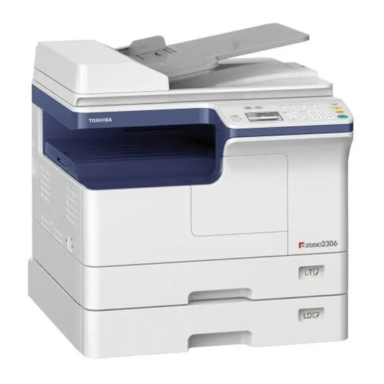
- Page 29 Total counter......Electronical counter Dimensions of the equipment.... See the figure below W575 x D565 (base is 540) x H 402 (mm) Fig. 2-1 © 2013-2017 TOSHIBA TEC CORPORATION All rights reserved e-STUDIO2006/2306/2506/2007/2307/2507/2303A/2303AM/2803AM/2309A/2809A SPECIFICATIONS / ACCESSORIES / OPTIONS / SUPPLIES...
- Page 30 <23LA/23LM/28LM> Approximately 24.5 kg (54.02 lb.) (excluding developer material and drum) <23HA/28HA> Approximately 25.0 kg (55.12 lb.) (excluding developer material and drum) e-STUDIO2006/2306/2506/2007/2307/2507/2303A/2303AM/2803AM/2309A/2809A © 2013-2017 TOSHIBA TEC CORPORATION All rights reserved SPECIFICATIONS / ACCESSORIES / OPTIONS / SUPPLIES 2 - 4...
-
Page 31: Copy
Size not Upper Lower specified specified A4, B5, A5-R, LT, ST-R A4-R, B5-R, LT-R B4, LG, FOLIO, 14.5 COMPUTER A3, LD © 2013-2017 TOSHIBA TEC CORPORATION All rights reserved e-STUDIO2006/2306/2506/2007/2307/2507/2303A/2303AM/2803AM/2309A/2809A SPECIFICATIONS / ACCESSORIES / OPTIONS / SUPPLIES 2 - 5... - Page 32 * “–” means “Not acceptable”. * The copy speed in the above table are available when originals are manually placed for single side, multiple copying. e-STUDIO2006/2306/2506/2007/2307/2507/2303A/2303AM/2803AM/2309A/2809A © 2013-2017 TOSHIBA TEC CORPORATION All rights reserved SPECIFICATIONS / ACCESSORIES / OPTIONS / SUPPLIES 2 - 6...
- Page 33 * Setting: when in the Text/Photo mode with Automatic density and APS/AMS set to OFF, or when in the sort mode with paper fed from the 1st drawer. © 2013-2017 TOSHIBA TEC CORPORATION All rights reserved e-STUDIO2006/2306/2506/2007/2307/2507/2303A/2303AM/2803AM/2309A/2809A SPECIFICATIONS / ACCESSORIES / OPTIONS / SUPPLIES...
-
Page 34: Print
* Measuring condition of the scanning speed: Scanning single-sided A4/LT originals in the Text/Photo mode with 100% reproduction ratio using the RADF. e-STUDIO2006/2306/2506/2007/2307/2507/2303A/2303AM/2803AM/2309A/2809A © 2013-2017 TOSHIBA TEC CORPORATION All rights reserved SPECIFICATIONS / ACCESSORIES / OPTIONS / SUPPLIES 2 - 8... -
Page 35: Accessories
Hong Kong MJD: Europe CND: China TWD: Taiwan Notes: Check that the above accessories are correctly co-packed at the time of unpacking. © 2013-2017 TOSHIBA TEC CORPORATION All rights reserved e-STUDIO2006/2306/2506/2007/2307/2507/2303A/2303AM/2803AM/2309A/2809A SPECIFICATIONS / ACCESSORIES / OPTIONS / SUPPLIES 2 - 9... -
Page 36: Options
MF-2505U/ MF-2505E Harness Kit GQ-1131 Fax Kit GD-1330 GD-1360 Desk MH-2507 Wireless LAN Module GN-1080 PS3 Kit (Post script 3) GA-1340/C e-STUDIO2006/2306/2506/2007/2307/2507/2303A/2303AM/2803AM/2309A/2809A © 2013-2017 TOSHIBA TEC CORPORATION All rights reserved SPECIFICATIONS / ACCESSORIES / OPTIONS / SUPPLIES 2 - 10... -
Page 37: System List
GQ-1131 MD-0106/C Damp Heater MF-2505U/E ASD, ARD, TWD: Standard equipment Paper Feed Unit ( PFU ) MY-1043/C Desk MH-2507 Fig. 2-2 © 2013-2017 TOSHIBA TEC CORPORATION All rights reserved e-STUDIO2006/2306/2506/2007/2307/2507/2303A/2303AM/2803AM/2309A/2809A SPECIFICATIONS / ACCESSORIES / OPTIONS / SUPPLIES 2 - 11... -
Page 38: H/23H/25H>
Paper Feed Unit ( PFU ) MY-1043/C Paper Feed Pedestal Drawer Module Desk ( PFP ) MH-2507 MY-1044/C KD-1039/C Fig. 2-3 e-STUDIO2006/2306/2506/2007/2307/2507/2303A/2303AM/2803AM/2309A/2809A © 2013-2017 TOSHIBA TEC CORPORATION All rights reserved SPECIFICATIONS / ACCESSORIES / OPTIONS / SUPPLIES 2 - 12... -
Page 39: La/23Lm/28Lm>
MD-0107/C GQ-1131 Damp Heater MF-2505U/E ASD, ARD, TWD: Standard equipment Paper Feed Unit ( PFU ) MY-1043/C Desk MH-2507 Fig. 2-4 © 2013-2017 TOSHIBA TEC CORPORATION All rights reserved e-STUDIO2006/2306/2506/2007/2307/2507/2303A/2303AM/2803AM/2309A/2809A SPECIFICATIONS / ACCESSORIES / OPTIONS / SUPPLIES 2 - 13... -
Page 40: Ha/28Ha>
Paper Feed Unit ( PFU ) MY-1043/C Drawer Module MY-1044/C Paper Feed Pedestal Desk ( PFP ) MH-2507 KD-1039/C Fig. 2-5 e-STUDIO2006/2306/2506/2007/2307/2507/2303A/2303AM/2803AM/2309A/2809A © 2013-2017 TOSHIBA TEC CORPORATION All rights reserved SPECIFICATIONS / ACCESSORIES / OPTIONS / SUPPLIES 2 - 14... -
Page 41: Supplies
A: Argentina/220-volt South America, P: Asia, PS: Asia, C: China, CS: China * 2) E: Europe, TS: Taiwan, U: North America, Argentina/220-volt South America, P: Asia(include Australia), PS: Asia, C: China, CS: China © 2013-2017 TOSHIBA TEC CORPORATION All rights reserved e-STUDIO2006/2306/2506/2007/2307/2507/2303A/2303AM/2803AM/2309A/2809A SPECIFICATIONS / ACCESSORIES / OPTIONS / SUPPLIES... - Page 42 © 2013-2017 TOSHIBA TEC CORPORATION All rights reserved SPECIFICATIONS / ACCESSORIES / OPTIONS / SUPPLIES 2 - 16...
-
Page 43: Outline Of The Machine
OUTLINE OF THE MACHINE Sectional View <20L/23L/25H, 20H/23H/25H> 1. Front side H2 H3 Fig. 3-1 2. Rear side CLT4 CLT1 CLT3 CLT2 Fig. 3-2 © 2013-2017 TOSHIBA TEC CORPORATION All rights reserved e-STUDIO2006/2306/2506/2007/2307/2507/2303A/2303AM/2803AM/2309A/2809A OUTLINE OF THE MACHINE 3 - 1... - Page 44 Original glass RADF original glass Contact image sensor unit (CIS) Platen sensor S7 <20H/23H/25H, 23HA/28HA only> Automatic original detection sensor-1 S9 <20H/23H/25H, 23HA/28HA only> e-STUDIO2006/2306/2506/2007/2307/2507/2303A/2303AM/2803AM/2309A/2809A © 2013-2017 TOSHIBA TEC CORPORATION All rights reserved OUTLINE OF THE MACHINE 3 - 2...
- Page 45 Toner supply cover opening/closing switch Toner supply cover opening/closing interlock switch Temperature/humidity sensor Switching regulator Right cover opening/closing interlock switch Upper transport roller (Option) © 2013-2017 TOSHIBA TEC CORPORATION All rights reserved e-STUDIO2006/2306/2506/2007/2307/2507/2303A/2303AM/2803AM/2309A/2809A OUTLINE OF THE MACHINE 3 - 3...
- Page 46 Exit motor ADU fan (Option) PS-FAN <23HA/28HA only> CLT1 Registration roller clutch CLT2 Drawer feed clutch CLT3 Bypass feed clutch CLT4 ADU clutch (Option) e-STUDIO2006/2306/2506/2007/2307/2507/2303A/2303AM/2803AM/2309A/2809A © 2013-2017 TOSHIBA TEC CORPORATION All rights reserved OUTLINE OF THE MACHINE 3 - 4...
-
Page 47: Electric Parts Layout
Electric Parts Layout 1. Scanner unit, control panel <20L/23L/25L> HPNL Fig. 3-5 <23LA/23LM/28LM> HPNL Fig. 3-6 © 2013-2017 TOSHIBA TEC CORPORATION All rights reserved e-STUDIO2006/2306/2506/2007/2307/2507/2303A/2303AM/2803AM/2309A/2809A OUTLINE OF THE MACHINE 3 - 5... - Page 48 <20H/23H/25H> HPNL Fig. 3-7 <23HA/28HA> HPNL Fig. 3-8 e-STUDIO2006/2306/2506/2007/2307/2507/2303A/2303AM/2803AM/2309A/2809A © 2013-2017 TOSHIBA TEC CORPORATION All rights reserved OUTLINE OF THE MACHINE 3 - 6...
-
Page 49: Power Supply
2. Power supply <20L/23L/25L/20H/23H/25H> HVPS LVPS Fig. 3-9 <23LA/23LM/28LM/23HA/28HA> LVPS PS-FAN HVPS Fig. 3-10 © 2013-2017 TOSHIBA TEC CORPORATION All rights reserved e-STUDIO2006/2306/2506/2007/2307/2507/2303A/2303AM/2803AM/2309A/2809A OUTLINE OF THE MACHINE 3 - 7... - Page 50 CTRG LAMP1 LAMP2 LDRS THMS1 THMO2 THMO1 THMS2 THMS3 Fig. 3-11 <23LA/23LM/28LM/23HA/28HA> CTIF CTRG LAMP1 LAMP2 LDRS THMS3 THMO2 THMS1 THMO1 THMS2 Fig. 3-12 e-STUDIO2006/2306/2506/2007/2307/2507/2303A/2303AM/2803AM/2309A/2809A © 2013-2017 TOSHIBA TEC CORPORATION All rights reserved OUTLINE OF THE MACHINE 3 - 8...
-
Page 51: Developer Unit
4. Developer unit <20L/23L/25L/20H/23H/25H> THMS4 THMO3 Fig. 3-13 <23LA/23LM/28LM/23HA/28HA> THMS4 THMO3 Fig. 3-14 © 2013-2017 TOSHIBA TEC CORPORATION All rights reserved e-STUDIO2006/2306/2506/2007/2307/2507/2303A/2303AM/2803AM/2309A/2809A OUTLINE OF THE MACHINE 3 - 9... -
Page 52: Drive Unit
5. Drive unit <20L/23L/25L/20H/23H/25H> CLT1 CLT2 MAIN Fig. 3-15 <23LA/23LM/28LM/23HA/28HA> CLT1 MAIN CLT2 Fig. 3-16 e-STUDIO2006/2306/2506/2007/2307/2507/2303A/2303AM/2803AM/2309A/2809A © 2013-2017 TOSHIBA TEC CORPORATION All rights reserved OUTLINE OF THE MACHINE 3 - 10... - Page 53 6. Bypass feed unit <20L/23L/25L/20H/23H/25H> Fig. 3-17 <23LA/23LM/28LM/23HA/28HA> Fig. 3-18 © 2013-2017 TOSHIBA TEC CORPORATION All rights reserved e-STUDIO2006/2306/2506/2007/2307/2507/2303A/2303AM/2803AM/2309A/2809A OUTLINE OF THE MACHINE 3 - 11...
-
Page 54: Drawer Unit
7. Drawer unit <20L/23L/25L/20H/23H/25H> Fig. 3-19 <23LA/23LM/28LM/23HA/28HA> Fig. 3-20 e-STUDIO2006/2306/2506/2007/2307/2507/2303A/2303AM/2803AM/2309A/2809A © 2013-2017 TOSHIBA TEC CORPORATION All rights reserved OUTLINE OF THE MACHINE 3 - 12... - Page 55 8. Automatic duplexing unit, bypass unit <20L/23L/25L/20H/23H/25H> CLT4 CLT3 Fig. 3-21 <23LA/23LM/28LM/23HA/28HA> CLT3 Fig. 3-22 © 2013-2017 TOSHIBA TEC CORPORATION All rights reserved e-STUDIO2006/2306/2506/2007/2307/2507/2303A/2303AM/2803AM/2309A/2809A OUTLINE OF THE MACHINE 3 - 13...
-
Page 56: Symbols And Functions Of Various Components
ADU sensor (Option) automatic duplexing unit Fig. 3-22 APS-R Detecting original size Fig. 3-7 7-29 Automatic original detection sensor- <20H/23H/23H, 23HA/28HA only> Fig. 3-8 e-STUDIO2006/2306/2506/2007/2307/2507/2303A/2303AM/2803AM/2309A/2809A © 2013-2017 TOSHIBA TEC CORPORATION All rights reserved OUTLINE OF THE MACHINE 3 - 14... -
Page 57: Electromagnetic Clutches
(HPNL board) panel Fig. 3-7 Fig. 3-8 LDRS PWA-F-LDRS Driving the laser diode Fig. 3-11 3-15 Laser driving PC board (LDRS Fig. 3-12 board) © 2013-2017 TOSHIBA TEC CORPORATION All rights reserved e-STUDIO2006/2306/2506/2007/2307/2507/2303A/2303AM/2803AM/2309A/2809A OUTLINE OF THE MACHINE 3 - 15... -
Page 58: Lamps And Heaters
17-35 Fuser front thermostat Fig. 3-12 THMO3 THRMST-CS-L Preventing overheating in the drum Fig. 3-13 6-17 Drum damp heater thermostat damp heater Fig. 3-14 e-STUDIO2006/2306/2506/2007/2307/2507/2303A/2303AM/2803AM/2309A/2809A © 2013-2017 TOSHIBA TEC CORPORATION All rights reserved OUTLINE OF THE MACHINE 3 - 16... -
Page 59: Others
Fig. 3-10 • Needle electrode • Main charger grid • Developer bias • Transfer bias • Separation bias • Transfer supporting bias © 2013-2017 TOSHIBA TEC CORPORATION All rights reserved e-STUDIO2006/2306/2506/2007/2307/2507/2303A/2303AM/2803AM/2309A/2809A OUTLINE OF THE MACHINE 3 - 17... -
Page 60: Copy Process
Transfer bias: Improves transfer efficiency. Transfer: Transfers the visible toner image on the photoconductive drum onto paper. e-STUDIO2006/2306/2506/2007/2307/2507/2303A/2303AM/2803AM/2309A/2809A © 2013-2017 TOSHIBA TEC CORPORATION All rights reserved OUTLINE OF THE MACHINE 3 - 18... -
Page 61: Comparison With E-Studio195 Series
Red LED 8. Cleaning • Method Cleaning blade • Recovered toner Reuse (There is the recovered toner supply mechanism.) © 2013-2017 TOSHIBA TEC CORPORATION All rights reserved e-STUDIO2006/2306/2506/2007/2307/2507/2303A/2303AM/2803AM/2309A/2809A OUTLINE OF THE MACHINE 3 - 19... - Page 62 Pressure roller: Pressure roller: PFA tube roller (ø25) PFA tube roller (ø22) • Heater Heater lamp Turned ON/OFF by thermistor e-STUDIO2006/2306/2506/2007/2307/2507/2303A/2303AM/2803AM/2309A/2809A © 2013-2017 TOSHIBA TEC CORPORATION All rights reserved OUTLINE OF THE MACHINE 3 - 20...
-
Page 63: General Operation
3.6.1 Overview of Operation Operation of equipment Operation during initializing, pre-running and ready Drawer feed copying by [START] button Bypass feed copying Copying operation © 2013-2017 TOSHIBA TEC CORPORATION All rights reserved e-STUDIO2006/2306/2506/2007/2307/2507/2303A/2303AM/2803AM/2309A/2809A OUTLINE OF THE MACHINE 3 - 21... -
Page 64: Description Of Operation
When no button is pressed for a certain period of time, - Set number “1” is displayed. Equipment returns to the normal ready state. e-STUDIO2006/2306/2506/2007/2307/2507/2303A/2303AM/2803AM/2309A/2809A © 2013-2017 TOSHIBA TEC CORPORATION All rights reserved OUTLINE OF THE MACHINE 3 - 22... - Page 65 Polygonal motor, main motor OFF Drum, fuser unit and developer unit stop Fans return to the ready rotation “READY” is displayed and the equipment enters the ready state © 2013-2017 TOSHIBA TEC CORPORATION All rights reserved e-STUDIO2006/2306/2506/2007/2307/2507/2303A/2303AM/2803AM/2309A/2809A OUTLINE OF THE MACHINE 3 - 23...
- Page 66 After a certain period of time, the bypass feed clutch OFF 4. Hereafter, the operation 3) through 6) of P. 3-23 "[ 3 ] Drawer feed copying (1st drawer paper feeding)" is repeated. e-STUDIO2006/2306/2506/2007/2307/2507/2303A/2303AM/2803AM/2309A/2809A © 2013-2017 TOSHIBA TEC CORPORATION All rights reserved OUTLINE OF THE MACHINE 3 - 24...
-
Page 67: Detection Of Abnormality
Paper empty sensor OFF “Add paper” is displayed The LED on the control panel corresponding to the drawer blinks [START] button disabled © 2013-2017 TOSHIBA TEC CORPORATION All rights reserved e-STUDIO2006/2306/2506/2007/2307/2507/2303A/2303AM/2803AM/2309A/2809A OUTLINE OF THE MACHINE 3 - 25... - Page 68 Fig. 3-25 • Immediately after the power ON Any of all sensors on paper transport path detects paper (ON) Paper jam (E030) e-STUDIO2006/2306/2506/2007/2307/2507/2303A/2303AM/2803AM/2309A/2809A © 2013-2017 TOSHIBA TEC CORPORATION All rights reserved OUTLINE OF THE MACHINE 3 - 26...
- Page 69 Check the error code displayed on the control panel when “Call for service” appears, and deal with the abnormality referring to the error code table. P. 8-7 "8.2 Error Code List" © 2013-2017 TOSHIBA TEC CORPORATION All rights reserved e-STUDIO2006/2306/2506/2007/2307/2507/2303A/2303AM/2803AM/2309A/2809A OUTLINE OF THE MACHINE...
-
Page 70: Control Panel
When the operator’s attention is required, graphic symbols appear with messages explaining the condition of the equipment in the LCD panel. <20L/23L/25L> For NAD and ARD, AUD Fig. 3-26 For other models Fig. 3-27 e-STUDIO2006/2306/2506/2007/2307/2507/2303A/2303AM/2803AM/2309A/2809A © 2013-2017 TOSHIBA TEC CORPORATION All rights reserved OUTLINE OF THE MACHINE 3 - 28... - Page 71 <20H/23H/25H> For NAD and ARD, AUD Fig. 3-28 For other models Fig. 3-29 © 2013-2017 TOSHIBA TEC CORPORATION All rights reserved e-STUDIO2006/2306/2506/2007/2307/2507/2303A/2303AM/2803AM/2309A/2809A OUTLINE OF THE MACHINE 3 - 29...
- Page 72 <23LA/23LM/28LM> For NAD and ARD, AUD Fig. 3-30 For other models Fig. 3-31 e-STUDIO2006/2306/2506/2007/2307/2507/2303A/2303AM/2803AM/2309A/2809A © 2013-2017 TOSHIBA TEC CORPORATION All rights reserved OUTLINE OF THE MACHINE 3 - 30...
- Page 73 <23HA/28HA> For NAD and ARD, AUD Fig. 3-32 For other models Fig. 3-33 © 2013-2017 TOSHIBA TEC CORPORATION All rights reserved e-STUDIO2006/2306/2506/2007/2307/2507/2303A/2303AM/2803AM/2309A/2809A OUTLINE OF THE MACHINE 3 - 31...
-
Page 74: Items Shown On The Display Panel
CLOSE SIDE COVER OF THE COPIER. Fig. 3-35 3. Service call display Displays error code and service call message. CALL FOR SERVICE C 010 Fig. 3-36 e-STUDIO2006/2306/2506/2007/2307/2507/2303A/2303AM/2803AM/2309A/2809A © 2013-2017 TOSHIBA TEC CORPORATION All rights reserved OUTLINE OF THE MACHINE 3 - 32... -
Page 75: Scanner
[5] Platen sensor (S7) <20H/23H/25H, 23HA/28HA only> [6] Automatic original detection sensor-1 (S9) <20H/23H/25H, 23HA/28HA only> [7] Automatic original detection sensor-2 (S10) <20H/23H/25H, 23HA/28HA only> © 2013-2017 TOSHIBA TEC CORPORATION All rights reserved e-STUDIO2006/2306/2506/2007/2307/2507/2303A/2303AM/2803AM/2309A/2809A OUTLINE OF THE MACHINE 3 - 33... -
Page 76: Composition
Scan motor (M1) Other Platen sensor (S7) <20H/23H/25H, 23HA/28HA only> Automatic original detection sensor-1 <20H/23H/25H, 23HA/28HA only> Automatic original detection sensor-2 <20H/23H/25H, 23HA/28HA only> e-STUDIO2006/2306/2506/2007/2307/2507/2303A/2303AM/2803AM/2309A/2809A © 2013-2017 TOSHIBA TEC CORPORATION All rights reserved OUTLINE OF THE MACHINE 3 - 34... -
Page 77: Functions
In order to realize the same-to-scale optical system of A3 width and 7344 image pixels, the equipment uses 17 CMOS sensors (each CMOS sensor has 432 image pixels per line) to make up a CMOS sensor of 600x600 dpi resolution for scanning. © 2013-2017 TOSHIBA TEC CORPORATION All rights reserved e-STUDIO2006/2306/2506/2007/2307/2507/2303A/2303AM/2803AM/2309A/2809A OUTLINE OF THE MACHINE... - Page 78 5. Automatic original detection sensor-1 / -2 (S9/S10) The size of an original placed on the glass is instantly detected using the APS sensors fixed on the base frame. e-STUDIO2006/2306/2506/2007/2307/2507/2303A/2303AM/2803AM/2309A/2809A © 2013-2017 TOSHIBA TEC CORPORATION All rights reserved OUTLINE OF THE MACHINE 3 - 36...
-
Page 79: Description Of Operation
The originals transferred from the RADF are scanned while they pass through the upper surface of the RADF original glass where the CIS unit (CIS) has stopped. © 2013-2017 TOSHIBA TEC CORPORATION All rights reserved e-STUDIO2006/2306/2506/2007/2307/2507/2303A/2303AM/2803AM/2309A/2809A OUTLINE OF THE MACHINE... -
Page 80: Laser Optical Unit
They must also be handled very carefully, because fingerprints, dirt, or dust on them will distort the image. Fig. 3-39 [1] Polygonal motor e-STUDIO2006/2306/2506/2007/2307/2507/2303A/2303AM/2803AM/2309A/2809A © 2013-2017 TOSHIBA TEC CORPORATION All rights reserved OUTLINE OF THE MACHINE 3 - 38... -
Page 81: Laser Precautions
The following laser warning label is on the frame visible when the right cover and the toner supply cover are opened. Fig. 3-40 © 2013-2017 TOSHIBA TEC CORPORATION All rights reserved e-STUDIO2006/2306/2506/2007/2307/2507/2303A/2303AM/2803AM/2309A/2809A OUTLINE OF THE MACHINE 3 - 39... - Page 82 “CAUTION. HOT”, “CAUTION. HIGH VOLTAGE”, “CAUTION. LASER BEAM”, etc. to see if there is any dirt on their surface and if they are properly stuck to the equipment. e-STUDIO2006/2306/2506/2007/2307/2507/2303A/2303AM/2803AM/2309A/2809A © 2013-2017 TOSHIBA TEC CORPORATION All rights reserved OUTLINE OF THE MACHINE 3 - 40...
-
Page 83: Drive System
[6] For toner cartridge auger [7] For drum [8] For bypass feed roller [9] For paper feed roller [10] Exit motor (M6) [11] Exit roller © 2013-2017 TOSHIBA TEC CORPORATION All rights reserved e-STUDIO2006/2306/2506/2007/2307/2507/2303A/2303AM/2803AM/2309A/2809A OUTLINE OF THE MACHINE 3 - 41... -
Page 84: Composition
The toner motor is a DC brush motor which is controlled by control signals output from the MAIN board. The driving force of the toner motor is transmitted to the toner cartridge via gears. e-STUDIO2006/2306/2506/2007/2307/2507/2303A/2303AM/2803AM/2309A/2809A © 2013-2017 TOSHIBA TEC CORPORATION All rights reserved OUTLINE OF THE MACHINE 3 - 42... -
Page 85: Paper Feeding System
[2] Drawer separation pad [3] Paper empty sensor [4] Bypass feed roller [5] Bypass paper sensor [6] Bypass separation pad [7] Registration sensor [8] Registration roller © 2013-2017 TOSHIBA TEC CORPORATION All rights reserved e-STUDIO2006/2306/2506/2007/2307/2507/2303A/2303AM/2803AM/2309A/2809A OUTLINE OF THE MACHINE 3 - 43... -
Page 86: Composition
Bypass unit Bypass feed roller Bypass separation pad Bypass paper sensor (S6) Bypass feed clutch (CLT3) Registration roller Registration roller clutch (CLT1) Registration sensor (S2) e-STUDIO2006/2306/2506/2007/2307/2507/2303A/2303AM/2803AM/2309A/2809A © 2013-2017 TOSHIBA TEC CORPORATION All rights reserved OUTLINE OF THE MACHINE 3 - 44... -
Page 87: Functions
(the amount of the paper bend before it is transported to the registration roller). Also, it is used to detect the trailing edge of the paper has passed the registration roller. © 2013-2017 TOSHIBA TEC CORPORATION All rights reserved e-STUDIO2006/2306/2506/2007/2307/2507/2303A/2303AM/2803AM/2309A/2809A OUTLINE OF THE MACHINE... -
Page 88: Operation
(S2) within a specified period of time or not is substituted for the paper jam detection. Fig. 3-44 [1] Drawer feed clutch [2] Drawer feed roller e-STUDIO2006/2306/2506/2007/2307/2507/2303A/2303AM/2803AM/2309A/2809A © 2013-2017 TOSHIBA TEC CORPORATION All rights reserved OUTLINE OF THE MACHINE 3 - 46... - Page 89 Fig. 3-45 [1] Drawer feed roller [2] Drawer separation pad © 2013-2017 TOSHIBA TEC CORPORATION All rights reserved e-STUDIO2006/2306/2506/2007/2307/2507/2303A/2303AM/2803AM/2309A/2809A OUTLINE OF THE MACHINE 3 - 47...
- Page 90 When the bypass feed clutch turns ON, the bypass feed roller rotates and transports the paper on the bypass tray to the registration roller. Fig. 3-46 [1] Bypass feed clutch [2] Bypass separation pad [3] Bypass feed roller e-STUDIO2006/2306/2506/2007/2307/2507/2303A/2303AM/2803AM/2309A/2809A © 2013-2017 TOSHIBA TEC CORPORATION All rights reserved OUTLINE OF THE MACHINE 3 - 48...
- Page 91 The paper transported by the bypass feed roller arrives at the registration roller. After it is aligned by the registration roller, the bypass feed roller stops. Fig. 3-47 [1] Bypass feed clutch [2] Bypass separation pad [3] Bypass feed roller [4] Spring © 2013-2017 TOSHIBA TEC CORPORATION All rights reserved e-STUDIO2006/2306/2506/2007/2307/2507/2303A/2303AM/2803AM/2309A/2809A OUTLINE OF THE MACHINE 3 - 49...
- Page 92 • The registration roller clutch (CLT1) is turned ON and the paper aligned by the registration roller is transported to the transfer unit. e-STUDIO2006/2306/2506/2007/2307/2507/2303A/2303AM/2803AM/2309A/2809A © 2013-2017 TOSHIBA TEC CORPORATION All rights reserved OUTLINE OF THE MACHINE 3 - 50...
-
Page 93: Drum Related Section
[9] Ozone filter [10] Separation needle [11] Transfer roller [12] Toner cartridge interface PC board (CTIF board) [13] Drum [14] Drum thermistor [15] Temperature/Humidity sensor © 2013-2017 TOSHIBA TEC CORPORATION All rights reserved e-STUDIO2006/2306/2506/2007/2307/2507/2303A/2303AM/2803AM/2309A/2809A OUTLINE OF THE MACHINE 3 - 51... -
Page 94: Composition
Main charger Needle electrode Grid Periodic replacement part Other High-voltage transformer Temperature/humidity sensor (S1) Suction fan (M5) Ozone filter Discharge LED Drum thermistor (THMS4) e-STUDIO2006/2306/2506/2007/2307/2507/2303A/2303AM/2803AM/2309A/2809A © 2013-2017 TOSHIBA TEC CORPORATION All rights reserved OUTLINE OF THE MACHINE 3 - 52... -
Page 95: Functions
This blade catches the toner scraped off by the cleaning blade. Toner recovery auger This auger carries the residual toner scraped off to the developer unit and reuses the toner. © 2013-2017 TOSHIBA TEC CORPORATION All rights reserved e-STUDIO2006/2306/2506/2007/2307/2507/2303A/2303AM/2803AM/2309A/2809A OUTLINE OF THE MACHINE... -
Page 96: Outline
The suction fan also helps the paper separation by absorbing the paper to post-transfer guide. e-STUDIO2006/2306/2506/2007/2307/2507/2303A/2303AM/2803AM/2309A/2809A © 2013-2017 TOSHIBA TEC CORPORATION All rights reserved OUTLINE OF THE MACHINE 3 - 54... -
Page 97: Development System
[2] Drum [3] Developer sleeve [4] Mixer-1 [5] Auto-toner sensor [6] Mixer-2 [7] Toner cartridge PC board (CTRG) [8] Toner cartridge interface PC board (CTIF) © 2013-2017 TOSHIBA TEC CORPORATION All rights reserved e-STUDIO2006/2306/2506/2007/2307/2507/2303A/2303AM/2803AM/2309A/2809A OUTLINE OF THE MACHINE 3 - 55... -
Page 98: Composition
Developer sleeve (Magnet roller) Doctor blade Auto-toner sensor (S4) Toner cartridge Toner cartridge PC board (CTRG) Toner cartridge interface PC board (CTIF) Toner motor (M2) e-STUDIO2006/2306/2506/2007/2307/2507/2303A/2303AM/2803AM/2309A/2809A © 2013-2017 TOSHIBA TEC CORPORATION All rights reserved OUTLINE OF THE MACHINE 3 - 56... -
Page 99: Functions
(M2). The toner cartridge in this equipment mounts the toner cartridge PC board (CTRG), and the data identifying recommended TOSHIBA toner cartridges and the counter values determining that the cartridge is nearly empty are written in this board. These data are read out by the toner cartridge interface PC board (CTIF) in this equipment, and data related to toner supply are also written in the toner cartridge PC board (CTRG). - Page 100 An IC chip is embedded in this board. Data such as identification information for the recommended TOSHIBA toner cartridge, thresholds to determine if the cartridge is nearly empty, and controlling data for the image quality to be optimal according to the toner characteristics are written in this chip.
-
Page 101: Setting
When a non-recommended toner cartridge is used, the equipment may stop normal operations. The toner remaining check function, automatic remote supply order to TOSHIBA sales representatives and image optimization function may also be disabled. - Page 102 Drum cleaner Mixer-1 Mixer-2 Toner recovery auger Toner cartridge Fresh toner Recovered toner Fig. 3-51 e-STUDIO2006/2306/2506/2007/2307/2507/2303A/2303AM/2803AM/2309A/2809A © 2013-2017 TOSHIBA TEC CORPORATION All rights reserved OUTLINE OF THE MACHINE 3 - 60...
-
Page 103: Fuser / Exit Unit
[3] Fuse center thermostat / fuser front thermostat [4] Center thermistor / edge thermistor [5] Fuser separation finger [6] Exit sensor [7] Pressure roller © 2013-2017 TOSHIBA TEC CORPORATION All rights reserved e-STUDIO2006/2306/2506/2007/2307/2507/2303A/2303AM/2803AM/2309A/2809A OUTLINE OF THE MACHINE 3 - 61... -
Page 104: Composition
Fuser roller PFA coated roller (23) Heater lamp (LAMP1, LAMP2) 600W+600W Thermistor (THMS1, THMS2, THMS3) Thermostat (THMO1, THMO2) Non-contact type Separation finger Exit roller e-STUDIO2006/2306/2506/2007/2307/2507/2303A/2303AM/2803AM/2309A/2809A © 2013-2017 TOSHIBA TEC CORPORATION All rights reserved OUTLINE OF THE MACHINE 3 - 62... -
Page 105: Functions
The exit motor is a stepping motor which drives the exit roller. For this motor rotates exit roller reversely to switchback when the paper is transported to the ADU. © 2013-2017 TOSHIBA TEC CORPORATION All rights reserved e-STUDIO2006/2306/2506/2007/2307/2507/2303A/2303AM/2803AM/2309A/2809A OUTLINE OF THE MACHINE... -
Page 106: Operation
And if printing is not performed within another specified period of time after the equipment has entered the Auto Power Save Mode, the equipment then enters the Auto Shut Off mode to turn OFF the heater lamp. e-STUDIO2006/2306/2506/2007/2307/2507/2303A/2303AM/2803AM/2309A/2809A © 2013-2017 TOSHIBA TEC CORPORATION All rights reserved OUTLINE OF THE MACHINE 3 - 64... -
Page 107: Heater Control Circuit
Relay (THMS1) (THMS2) (THMS3) converter ASIC Temperature control circuit AC line DC line Relay OFF signal Relay OFF circuit MAIN board (MAIN) Fig. 3-53 © 2013-2017 TOSHIBA TEC CORPORATION All rights reserved e-STUDIO2006/2306/2506/2007/2307/2507/2303A/2303AM/2803AM/2309A/2809A OUTLINE OF THE MACHINE 3 - 65... - Page 108 Relay (THMS3) (THMS1) (THMS2) converter ASIC Temperature control circuit AC line DC line Relay OFF signal Relay OFF circuit MAIN board (MAIN) Fig. 3-54 e-STUDIO2006/2306/2506/2007/2307/2507/2303A/2303AM/2803AM/2309A/2809A © 2013-2017 TOSHIBA TEC CORPORATION All rights reserved OUTLINE OF THE MACHINE 3 - 66...
- Page 109 After confirming that it is the fuser unit abnormality, correct the abnormality and reset the counter value (08-2002) to “0” to start up the equipment normally. © 2013-2017 TOSHIBA TEC CORPORATION All rights reserved e-STUDIO2006/2306/2506/2007/2307/2507/2303A/2303AM/2803AM/2309A/2809A OUTLINE OF THE MACHINE...
- Page 110 240ºC Ready Center 70ºC temperature Ready C452 62 confirmed Ready temperature Center 70ºC temperature C-Ready S-Ready Ready temperature C414 4 confirmed Ready temperature e-STUDIO2006/2306/2506/2007/2307/2507/2303A/2303AM/2803AM/2309A/2809A © 2013-2017 TOSHIBA TEC CORPORATION All rights reserved OUTLINE OF THE MACHINE 3 - 68...
- Page 111 240ºC 240ºC When Constantly C449 29 confirmed 240ºC jammed detected 240ºC 240ºC During self- Constantly C449 45 confirmed 240ºC diagnosis detected 240ºC © 2013-2017 TOSHIBA TEC CORPORATION All rights reserved e-STUDIO2006/2306/2506/2007/2307/2507/2303A/2303AM/2803AM/2309A/2809A OUTLINE OF THE MACHINE 3 - 69...
-
Page 112: Automatic Duplexing Unit
[3] ADU upper transport roller [5] ADU motor [6] ADU lower transport roller [8] ADU clutch [9] Exit roller [10] Paper exit section [11] Fuser section e-STUDIO2006/2306/2506/2007/2307/2507/2303A/2303AM/2803AM/2309A/2809A © 2013-2017 TOSHIBA TEC CORPORATION All rights reserved OUTLINE OF THE MACHINE 3 - 70... -
Page 113: Composition
3.15.2 Composition Automatic Duplexing Unit (ADU) ADU clutch CLT4 ADU sensor ADU upper transport roller ADU lower transport roller Exit motor © 2013-2017 TOSHIBA TEC CORPORATION All rights reserved e-STUDIO2006/2306/2506/2007/2307/2507/2303A/2303AM/2803AM/2309A/2809A OUTLINE OF THE MACHINE 3 - 71... -
Page 114: Drive Of Adu
ADU lower transport roller is rotated. Fig. 3-56 [1] ADU upper transport roller [2] ADU lower transport roller [3] ADU clutch [4] Main motor (M3) e-STUDIO2006/2306/2506/2007/2307/2507/2303A/2303AM/2803AM/2309A/2809A © 2013-2017 TOSHIBA TEC CORPORATION All rights reserved OUTLINE OF THE MACHINE 3 - 72... -
Page 115: Functions
4. ADU upper transport roller, ADU lower transport roller Transports the paper inside the ADU. 5. ADU fan (M7) Cooling down the process unit and the toner cartridge. © 2013-2017 TOSHIBA TEC CORPORATION All rights reserved e-STUDIO2006/2306/2506/2007/2307/2507/2303A/2303AM/2803AM/2309A/2809A OUTLINE OF THE MACHINE 3 - 73... -
Page 116: Description Of Operations
The figures in the following pages show the circulating operations during duplex copying. The numbers in the figures indicate the page numbers. e-STUDIO2006/2306/2506/2007/2307/2507/2303A/2303AM/2803AM/2309A/2809A © 2013-2017 TOSHIBA TEC CORPORATION All rights reserved OUTLINE OF THE MACHINE 3 - 74... - Page 117 With the paper larger than A4/LT size, duplex printing (back-side printing front-side printing) is performed for one sheet at a time as shown below. Fig. 3-57 © 2013-2017 TOSHIBA TEC CORPORATION All rights reserved e-STUDIO2006/2306/2506/2007/2307/2507/2303A/2303AM/2803AM/2309A/2809A OUTLINE OF THE MACHINE...
-
Page 118: Power Supply Unit
Notes: The Power Supply Unit does not supply power to the Damp heater. Damp heater power is supplied from the FUS board. e-STUDIO2006/2306/2506/2007/2307/2507/2303A/2303AM/2803AM/2309A/2809A © 2013-2017 TOSHIBA TEC CORPORATION All rights reserved OUTLINE OF THE MACHINE 3 - 76... -
Page 119: Operation Of Dc Output Circuits
Only +5VS DC voltage is outputted from the power supply unit and the [ENERGY SAVER] button is monitored and turned on. The machine is in a sleep state at this time. © 2013-2017 TOSHIBA TEC CORPORATION All rights reserved e-STUDIO2006/2306/2506/2007/2307/2507/2303A/2303AM/2803AM/2309A/2809A... -
Page 120: Output Channel
The outputs below are linked with the door switch. 1. +24V +24VD-OUT : CN109 Pin 1 Output to the MAIN board +24VD-IN CN109 Pin 3 Output to the MAIN board e-STUDIO2006/2306/2506/2007/2307/2507/2303A/2303AM/2803AM/2309A/2809A © 2013-2017 TOSHIBA TEC CORPORATION All rights reserved OUTLINE OF THE MACHINE 3 - 78... -
Page 121: Disassembly And Replacement
Remove 2 screws and take off the left cover [1]. Fig. 4-2 4.1.2 Left cover <23LA/23LM/28LM/23HA/28HA> Remove 2 screws and take off the left cover [1]. Fig. 4-3 © 2013-2017 TOSHIBA TEC CORPORATION All rights reserved e-STUDIO2006/2306/2506/2007/2307/2507/2303A/2303AM/2803AM/2309A/2809A DISASSEMBLY AND REPLACEMENT 4 - 1... -
Page 122: Inner Tray
Take off the inner tray [1]. Fig. 4-4 4.1.4 Right front cover Take off the drawer. Open the toner supply cover [1]. Fig. 4-5 Remove 2 screws. Fig. 4-6 e-STUDIO2006/2306/2506/2007/2307/2507/2303A/2303AM/2803AM/2309A/2809A © 2013-2017 TOSHIBA TEC CORPORATION All rights reserved DISASSEMBLY AND REPLACEMENT 4 - 2... -
Page 123: Left Front Cover
Take off the inner tray. P. 4-2 "4.1.3 Inner tray" Remove 5 screws and then take off the left front cover [1]. Fig. 4-9 © 2013-2017 TOSHIBA TEC CORPORATION All rights reserved e-STUDIO2006/2306/2506/2007/2307/2507/2303A/2303AM/2803AM/2309A/2809A DISASSEMBLY AND REPLACEMENT 4 - 3... - Page 124 Take off the tray rear cover [1]. Notes: When installing the tray rear cover, hook the hole of the tray rear cover on the hook of the frame. Fig. 4-12 e-STUDIO2006/2306/2506/2007/2307/2507/2303A/2303AM/2803AM/2309A/2809A © 2013-2017 TOSHIBA TEC CORPORATION All rights reserved DISASSEMBLY AND REPLACEMENT 4 - 4...
- Page 125 Remove 3 screws and take off the rear cover [1]. Notes: When attaching the rear cover, be sure to insert the two hooks on its right side before tightening the screws. Fig. 4-13 © 2013-2017 TOSHIBA TEC CORPORATION All rights reserved e-STUDIO2006/2306/2506/2007/2307/2507/2303A/2303AM/2803AM/2309A/2809A DISASSEMBLY AND REPLACEMENT 4 - 5...
- Page 126 Remove 1 screw and take off the connector cover [1]. Fig. 4-14 Disconnect 1 connector. Fig. 4-15 Remove 3 screws. Fig. 4-16 Take off the rear cover [2]. Fig. 4-17 e-STUDIO2006/2306/2506/2007/2307/2507/2303A/2303AM/2803AM/2309A/2809A © 2013-2017 TOSHIBA TEC CORPORATION All rights reserved DISASSEMBLY AND REPLACEMENT 4 - 6...
-
Page 127: Right Rear Cover
[1]. Fig. 4-18 4.1.12 Right lower cover Take off the drawer. Release 2 latches and then take off the right lower cover [1]. Fig. 4-19 © 2013-2017 TOSHIBA TEC CORPORATION All rights reserved e-STUDIO2006/2306/2506/2007/2307/2507/2303A/2303AM/2803AM/2309A/2809A DISASSEMBLY AND REPLACEMENT 4 - 7... -
Page 128: Right Cover
Pull out a shaft while supporting the right cover by hand so that it may not fall. Fig. 4-21 Remove the right cover [4]. Fig. 4-22 e-STUDIO2006/2306/2506/2007/2307/2507/2303A/2303AM/2803AM/2309A/2809A © 2013-2017 TOSHIBA TEC CORPORATION All rights reserved DISASSEMBLY AND REPLACEMENT 4 - 8... -
Page 129: Top Cover
P. 4-10 "4.2.1 Control panel unit" Remove 7 screws and take off the top cover [1]. Remarks: The top cover is pasted with the original glass. Fig. 4-23 © 2013-2017 TOSHIBA TEC CORPORATION All rights reserved e-STUDIO2006/2306/2506/2007/2307/2507/2303A/2303AM/2803AM/2309A/2809A DISASSEMBLY AND REPLACEMENT 4 - 9... -
Page 130: Control Panel
[1] to the right and remove it. Fig. 4-24 Remove 2 screws. Fig. 4-25 Release the 5 latches and take off the control panel unit [2]. Fig. 4-26 e-STUDIO2006/2306/2506/2007/2307/2507/2303A/2303AM/2803AM/2309A/2809A © 2013-2017 TOSHIBA TEC CORPORATION All rights reserved DISASSEMBLY AND REPLACEMENT 4 - 10... - Page 131 Take off the control panel PC board. P. 4-11 "4.2.2 Control panel PC board (HPNL)" Release 2 latches and take off the LED panel cover [1]. Fig. 4-29 © 2013-2017 TOSHIBA TEC CORPORATION All rights reserved e-STUDIO2006/2306/2506/2007/2307/2507/2303A/2303AM/2803AM/2309A/2809A DISASSEMBLY AND REPLACEMENT 4 - 11...
- Page 132 USB cable [3] from the main board [2]. Fig. 4-31 Remove 4 screws, lift the scanner unit [4] a little and then remove the USB cable [5]. Fig. 4-32 e-STUDIO2006/2306/2506/2007/2307/2507/2303A/2303AM/2803AM/2309A/2809A © 2013-2017 TOSHIBA TEC CORPORATION All rights reserved DISASSEMBLY AND REPLACEMENT 4 - 12...
- Page 133 Remove the USB cable [2] from the MAIN board [1]. Fig. 4-34 Remove 4 screws, lift the scanner unit [3] a little and then remove the USB cable [4]. Fig. 4-35 © 2013-2017 TOSHIBA TEC CORPORATION All rights reserved e-STUDIO2006/2306/2506/2007/2307/2507/2303A/2303AM/2803AM/2309A/2809A DISASSEMBLY AND REPLACEMENT 4 - 13...
- Page 134 Release the latch [5] and remove the USB cable [7] from the cable hook [6]. Fig. 4-36 e-STUDIO2006/2306/2506/2007/2307/2507/2303A/2303AM/2803AM/2309A/2809A © 2013-2017 TOSHIBA TEC CORPORATION All rights reserved DISASSEMBLY AND REPLACEMENT 4 - 14...
-
Page 135: Scanner
Notes: Since the pulley comes off easily, hold down the pulley with your finger as you move the CIS unit. <20L/23L/25L, 20H/23H/25H only> Fig. 4-39 © 2013-2017 TOSHIBA TEC CORPORATION All rights reserved e-STUDIO2006/2306/2506/2007/2307/2507/2303A/2303AM/2803AM/2309A/2809A DISASSEMBLY AND REPLACEMENT 4 - 15... - Page 136 CIS case. Fig. 4-41 7. After installing the CIS unit, move it to the left side of the equipment. Fig. 4-42 e-STUDIO2006/2306/2506/2007/2307/2507/2303A/2303AM/2803AM/2309A/2809A © 2013-2017 TOSHIBA TEC CORPORATION All rights reserved DISASSEMBLY AND REPLACEMENT 4 - 16...
- Page 137 Notes: Since the pulley comes off easily, hold down the pulley with your finger as you move the CIS unit. <20L/23L/25L, 20H/23H/25H only> Fig. 4-43 © 2013-2017 TOSHIBA TEC CORPORATION All rights reserved e-STUDIO2006/2306/2506/2007/2307/2507/2303A/2303AM/2803AM/2309A/2809A DISASSEMBLY AND REPLACEMENT 4 - 17...
- Page 138 [5] to the front side, and brown spring [6] to the rear side. [ 5 ] Fig. 4-45 Remove the CIS unit drive belt [4]. Fig. 4-46 e-STUDIO2006/2306/2506/2007/2307/2507/2303A/2303AM/2803AM/2309A/2809A © 2013-2017 TOSHIBA TEC CORPORATION All rights reserved DISASSEMBLY AND REPLACEMENT 4 - 18...
- Page 139 If the spring comes off, it is attached black spring [5] to the front side, and brown [ 3 ] spring [6] to the rear side. [ 5 ] Fig. 4-49 © 2013-2017 TOSHIBA TEC CORPORATION All rights reserved e-STUDIO2006/2306/2506/2007/2307/2507/2303A/2303AM/2803AM/2309A/2809A DISASSEMBLY AND REPLACEMENT 4 - 19...
- Page 140 Remove the CIS unit drive belt [4]. Fig. 4-50 e-STUDIO2006/2306/2506/2007/2307/2507/2303A/2303AM/2803AM/2309A/2809A © 2013-2017 TOSHIBA TEC CORPORATION All rights reserved DISASSEMBLY AND REPLACEMENT 4 - 20...
- Page 141 (Color of gear: white and black) Fig. 4-52 Remarks: That shown on the right is an example of the one-gear type. (Color of gear: white) Fig. 4-53 © 2013-2017 TOSHIBA TEC CORPORATION All rights reserved e-STUDIO2006/2306/2506/2007/2307/2507/2303A/2303AM/2803AM/2309A/2809A DISASSEMBLY AND REPLACEMENT 4 - 21...
- Page 142 That shown on the right is an example of the two-gear type. • This is the common step for both the one- gear and two-gear types. Fig. 4-56 e-STUDIO2006/2306/2506/2007/2307/2507/2303A/2303AM/2803AM/2309A/2809A © 2013-2017 TOSHIBA TEC CORPORATION All rights reserved DISASSEMBLY AND REPLACEMENT 4 - 22...
- Page 143 Remarks: This is the common step for both the one- gear and two-gear types. Fig. 4-57 Fig. 4-58 © 2013-2017 TOSHIBA TEC CORPORATION All rights reserved e-STUDIO2006/2306/2506/2007/2307/2507/2303A/2303AM/2803AM/2309A/2809A DISASSEMBLY AND REPLACEMENT 4 - 23...
- Page 144 Take off the CIS case. P. 4-18 "4.3.3 CIS case" Remove the gear [2]. Fig. 4-60 Remove 2 screws and take off the motor bracket [3]. Fig. 4-61 e-STUDIO2006/2306/2506/2007/2307/2507/2303A/2303AM/2803AM/2309A/2809A © 2013-2017 TOSHIBA TEC CORPORATION All rights reserved DISASSEMBLY AND REPLACEMENT 4 - 24...
- Page 145 When attaching the fuser thermostat, place the round terminal of the cable above the thermostat terminal, and attach in the direction shown in the figure. Fig. 4-64 © 2013-2017 TOSHIBA TEC CORPORATION All rights reserved e-STUDIO2006/2306/2506/2007/2307/2507/2303A/2303AM/2803AM/2309A/2809A DISASSEMBLY AND REPLACEMENT 4 - 25...
- Page 146 P. 4-15 "4.3.1 Original glass" Remove actuator [1] and remove 1 connector [2]. Fig. 4-66 Release 2 latches and then remove the platen sensor [3]. Fig. 4-67 e-STUDIO2006/2306/2506/2007/2307/2507/2303A/2303AM/2803AM/2309A/2809A © 2013-2017 TOSHIBA TEC CORPORATION All rights reserved DISASSEMBLY AND REPLACEMENT 4 - 26...
- Page 147 (S9) [2]. Fig. 4-68 Remove the 1 connector [3], release 3 latches and the automatic original detection sensor-2 (S10) [4]. Fig. 4-69 © 2013-2017 TOSHIBA TEC CORPORATION All rights reserved e-STUDIO2006/2306/2506/2007/2307/2507/2303A/2303AM/2803AM/2309A/2809A DISASSEMBLY AND REPLACEMENT 4 - 27...
-
Page 148: Laser Optical Unit
Fig. 4-71 Remove 2 screws and raise the laser optical unit [2] to take it off. Fig. 4-72 e-STUDIO2006/2306/2506/2007/2307/2507/2303A/2303AM/2803AM/2309A/2809A © 2013-2017 TOSHIBA TEC CORPORATION All rights reserved DISASSEMBLY AND REPLACEMENT 4 - 28... - Page 149 [3]. 6. Do not allow dirt or foreign objects to touch the HSYNC mirror (interior) [4]. © 2013-2017 TOSHIBA TEC CORPORATION All rights reserved e-STUDIO2006/2306/2506/2007/2307/2507/2303A/2303AM/2803AM/2309A/2809A DISASSEMBLY AND REPLACEMENT 4 - 29...
-
Page 150: Main Motor (M3)
[1]. Fig. 4-75 Take off the toner motor [2] with the bracket, and then remove 1 bushing [3] and 1 gear [4]. Fig. 4-76 e-STUDIO2006/2306/2506/2007/2307/2507/2303A/2303AM/2803AM/2309A/2809A © 2013-2017 TOSHIBA TEC CORPORATION All rights reserved DISASSEMBLY AND REPLACEMENT 4 - 30... -
Page 151: Paper Eject Unit
Notes: Pay attention to the size (length) of the screws. If incorrect ones are used, the screw hole of frame could be damaged. Fig. 4-79 © 2013-2017 TOSHIBA TEC CORPORATION All rights reserved e-STUDIO2006/2306/2506/2007/2307/2507/2303A/2303AM/2803AM/2309A/2809A DISASSEMBLY AND REPLACEMENT 4 - 31... -
Page 152: Lower Drive Unit
[1]. Notes: Pay attention to the size (length) of the screws. If incorrect ones are used, the screw hole of frame could be damaged. e-STUDIO2006/2306/2506/2007/2307/2507/2303A/2303AM/2803AM/2309A/2809A © 2013-2017 TOSHIBA TEC CORPORATION All rights reserved DISASSEMBLY AND REPLACEMENT 4 - 32... -
Page 153: Bypass Unit
Remove the 1 screw and then remove the link arm [2]. Fig. 4-82 Remove the bypass unit [3] in a downward slanting direction. Fig. 4-83 © 2013-2017 TOSHIBA TEC CORPORATION All rights reserved e-STUDIO2006/2306/2506/2007/2307/2507/2303A/2303AM/2803AM/2309A/2809A DISASSEMBLY AND REPLACEMENT 4 - 33... -
Page 154: Bypass Feed Clutch (Clt3)
When attaching the earth, run the earth wire around [6] as shown in the figure. Fig. 4-85 Remove the plate [2], 1 bushing [3], and then bypass feed clutch [4]. Fig. 4-86 e-STUDIO2006/2306/2506/2007/2307/2507/2303A/2303AM/2803AM/2309A/2809A © 2013-2017 TOSHIBA TEC CORPORATION All rights reserved DISASSEMBLY AND REPLACEMENT 4 - 34... -
Page 155: Duct Unit
[6] when attaching it. Fig. 4-88 4.6.3 Duct unit Open the right cover. While releasing 2 latches, take off the duct unit [1]. Fig. 4-89 © 2013-2017 TOSHIBA TEC CORPORATION All rights reserved e-STUDIO2006/2306/2506/2007/2307/2507/2303A/2303AM/2803AM/2309A/2809A DISASSEMBLY AND REPLACEMENT 4 - 35... -
Page 156: Lower Bypass Feed Guide
Take off the Lower bypass feed guide. P. 4-36 "4.6.4 Lower bypass feed guide" Remove 2 clips [1] and then slide the shaft [2] to the rear side. Fig. 4-92 e-STUDIO2006/2306/2506/2007/2307/2507/2303A/2303AM/2803AM/2309A/2809A © 2013-2017 TOSHIBA TEC CORPORATION All rights reserved DISASSEMBLY AND REPLACEMENT 4 - 36... -
Page 157: Bypass Feed Roller <23La/23Lm/28Lm/23Ha/28Ha>
[5] with the groove on the feed roller and then clip it on with the clip. Fig. 4-94 4.6.6 Bypass feed roller <23LA/23LM/28LM/23HA/28HA> Open the bypass feed roller [1]. Fig. 4-95 © 2013-2017 TOSHIBA TEC CORPORATION All rights reserved e-STUDIO2006/2306/2506/2007/2307/2507/2303A/2303AM/2803AM/2309A/2809A DISASSEMBLY AND REPLACEMENT 4 - 37... - Page 158 When attaching the bypass feed roller, align the convex part on the feed roller side with the concave part on the equipment side. Fig. 4-97 e-STUDIO2006/2306/2506/2007/2307/2507/2303A/2303AM/2803AM/2309A/2809A © 2013-2017 TOSHIBA TEC CORPORATION All rights reserved DISASSEMBLY AND REPLACEMENT 4 - 38...
-
Page 159: Bypass Separation Pad <20L/23L/25L/20H/23H/25H>
P. 4-37 "4.6.6 Bypass feed roller <23LA/ 23LM/28LM/23HA/28HA>" Release 3 latches, take off the bypass paper sensor [1], and disconnect the connector. Fig. 4-99 © 2013-2017 TOSHIBA TEC CORPORATION All rights reserved e-STUDIO2006/2306/2506/2007/2307/2507/2303A/2303AM/2803AM/2309A/2809A DISASSEMBLY AND REPLACEMENT 4 - 39... -
Page 160: Drawer Feed Roller <20L/23L/25L/20H/23H/25H>
[2] to the rear side. Fig. 4-100 Remove the clip [3]. Fig. 4-101 Take off the drawer feed roller [4]. Fig. 4-102 e-STUDIO2006/2306/2506/2007/2307/2507/2303A/2303AM/2803AM/2309A/2809A © 2013-2017 TOSHIBA TEC CORPORATION All rights reserved DISASSEMBLY AND REPLACEMENT 4 - 40... -
Page 161: Drawer Feed Roller <23La/23Lm/28Lm/23Ha/28Ha>
[2] to the rear side. Fig. 4-103 Remove the clip [3]. Fig. 4-104 Remove the 1 collar [4] and take off the drawer feed roller [5]. Fig. 4-105 © 2013-2017 TOSHIBA TEC CORPORATION All rights reserved e-STUDIO2006/2306/2506/2007/2307/2507/2303A/2303AM/2803AM/2309A/2809A DISASSEMBLY AND REPLACEMENT 4 - 41... -
Page 162: Drawer Separation Pad
P. 4-6 "4.1.10 Rear cover <23LA/23LM/ 28LM/23HA/28HA>" Disconnect 1 connector [1]. Fig. 4-107 Remove 1 screw, release 1 latch and then take off the clutch cover [2]. Fig. 4-108 e-STUDIO2006/2306/2506/2007/2307/2507/2303A/2303AM/2803AM/2309A/2809A © 2013-2017 TOSHIBA TEC CORPORATION All rights reserved DISASSEMBLY AND REPLACEMENT 4 - 42... -
Page 163: Registration Roller Clutch (Clt1)
Notes: When installing the registration roller clutch [3], engage the arm of the clutch with the rotation stopper of the lower drive unit. Fig. 4-111 © 2013-2017 TOSHIBA TEC CORPORATION All rights reserved e-STUDIO2006/2306/2506/2007/2307/2507/2303A/2303AM/2803AM/2309A/2809A DISASSEMBLY AND REPLACEMENT 4 - 43... -
Page 164: Registration Roller (Metal)
(metal). Fig. 4-113 Remove 1 E-ring [3] and 1 gear [4]. Fig. 4-114 e-STUDIO2006/2306/2506/2007/2307/2507/2303A/2303AM/2803AM/2309A/2809A © 2013-2017 TOSHIBA TEC CORPORATION All rights reserved DISASSEMBLY AND REPLACEMENT 4 - 44... -
Page 165: Registration Roller (Rubber)
Remove 2 washers [3] and 1 gear [4]. Fig. 4-116 Notes: When installing the 2 washers [3], it attaches to the position of a figure. Fig. 4-117 © 2013-2017 TOSHIBA TEC CORPORATION All rights reserved e-STUDIO2006/2306/2506/2007/2307/2507/2303A/2303AM/2803AM/2309A/2809A DISASSEMBLY AND REPLACEMENT 4 - 45... -
Page 166: Registration Sensor (S2)
Remove the actuator [3] and the springs [4] and then release the 3 latches to remove the registration sensor [5]. Disconnect 1 connector [6]. Fig. 4-120 e-STUDIO2006/2306/2506/2007/2307/2507/2303A/2303AM/2803AM/2309A/2809A © 2013-2017 TOSHIBA TEC CORPORATION All rights reserved DISASSEMBLY AND REPLACEMENT 4 - 46... -
Page 167: Paper Empty Sensor (S5)
Remove 1 screw and then take off the damp heater unit or dummy plate [3] while sliding it to the rear and lifting it down. Fig. 4-123 © 2013-2017 TOSHIBA TEC CORPORATION All rights reserved e-STUDIO2006/2306/2506/2007/2307/2507/2303A/2303AM/2803AM/2309A/2809A DISASSEMBLY AND REPLACEMENT 4 - 47... - Page 168 Turn over the damp heater unit or dummy plate. Disconnect 1 connector [4], release 3 latches. Take off paper empty sensor [5]. Fig. 4-124 e-STUDIO2006/2306/2506/2007/2307/2507/2303A/2303AM/2803AM/2309A/2809A © 2013-2017 TOSHIBA TEC CORPORATION All rights reserved DISASSEMBLY AND REPLACEMENT 4 - 48...
-
Page 169: Process Unit <20L/23L/25L/20H/23H/25H>
2. Be careful not to touch or scratch the drum surface. 3. Avoid direct light. Place the drum in a dark place immediately after taking off. Fig. 4-126 © 2013-2017 TOSHIBA TEC CORPORATION All rights reserved e-STUDIO2006/2306/2506/2007/2307/2507/2303A/2303AM/2803AM/2309A/2809A DISASSEMBLY AND REPLACEMENT 4 - 49... -
Page 170: Process Unit <23La/23Lm/28Lm/23Ha/28Ha>
Push the lever [2] and release the lock. Fig. 4-128 Notes: Check the marked lines and push the lever to the position shown in the figure. Fig. 4-129 e-STUDIO2006/2306/2506/2007/2307/2507/2303A/2303AM/2803AM/2309A/2809A © 2013-2017 TOSHIBA TEC CORPORATION All rights reserved DISASSEMBLY AND REPLACEMENT 4 - 50... -
Page 171: Drum Cleaner Unit
4. Keep in mind that there is a possibility that a toner may fall, from the used toner discharge part of a drum cleaner unit. Fig. 4-132 © 2013-2017 TOSHIBA TEC CORPORATION All rights reserved e-STUDIO2006/2306/2506/2007/2307/2507/2303A/2303AM/2803AM/2309A/2809A DISASSEMBLY AND REPLACEMENT 4 - 51... -
Page 172: Drum
Be sure to apply patting powder (lubricant) to the entire surface of the drum when the drum cleaning blade is replaced or it is cleaned. Fig. 4-135 e-STUDIO2006/2306/2506/2007/2307/2507/2303A/2303AM/2803AM/2309A/2809A © 2013-2017 TOSHIBA TEC CORPORATION All rights reserved DISASSEMBLY AND REPLACEMENT 4 - 52... -
Page 173: Recovery Blade
2. When the drum separation fingers have been replaced, check if the pressure movement is normal by moving them with your hands. Fig. 4-138 © 2013-2017 TOSHIBA TEC CORPORATION All rights reserved e-STUDIO2006/2306/2506/2007/2307/2507/2303A/2303AM/2803AM/2309A/2809A DISASSEMBLY AND REPLACEMENT 4 - 53... -
Page 174: Main Charger
Release the latch of the tensioner and take off the main charger grid [1]. Notes: Do not touch the mesh area of the grid. Fig. 4-141 e-STUDIO2006/2306/2506/2007/2307/2507/2303A/2303AM/2803AM/2309A/2809A © 2013-2017 TOSHIBA TEC CORPORATION All rights reserved DISASSEMBLY AND REPLACEMENT 4 - 54... -
Page 175: Main Charger Cleaner
2. Make sure not to hold or bend the needle electrode. Fig. 4-143 4.7.12 Transfer roller Open the right cover. Take off the transfer roller [1]. Fig. 4-144 © 2013-2017 TOSHIBA TEC CORPORATION All rights reserved e-STUDIO2006/2306/2506/2007/2307/2507/2303A/2303AM/2803AM/2309A/2809A DISASSEMBLY AND REPLACEMENT 4 - 55... -
Page 176: Separation Needle
Ozone filter Open the right cover. Take off the duct unit. P. 4-35 "4.6.3 Duct unit" Take off the ozone filter [1]. Fig. 4-147 e-STUDIO2006/2306/2506/2007/2307/2507/2303A/2303AM/2803AM/2309A/2809A © 2013-2017 TOSHIBA TEC CORPORATION All rights reserved DISASSEMBLY AND REPLACEMENT 4 - 56... -
Page 177: Suction Fun (M5)
Take off the left cover. P. 4-1 "4.1.2 Left cover <23LA/23LM/ 28LM/23HA/28HA>" While pressing the lever [1], take off the temperature/humidity sensor [2] with the holder. Fig. 4-150 © 2013-2017 TOSHIBA TEC CORPORATION All rights reserved e-STUDIO2006/2306/2506/2007/2307/2507/2303A/2303AM/2803AM/2309A/2809A DISASSEMBLY AND REPLACEMENT 4 - 57... - Page 178 Disconnect 1 connector [3] and 2 latches [4] and take off the temperature/humidity sensor [5]. Fig. 4-151 e-STUDIO2006/2306/2506/2007/2307/2507/2303A/2303AM/2803AM/2309A/2809A © 2013-2017 TOSHIBA TEC CORPORATION All rights reserved DISASSEMBLY AND REPLACEMENT 4 - 58...
-
Page 179: Developer Unit
Take off the developer unit. P. 4-59 "4.7.18 Developer unit" Release 2 latches and then take off the developer unit upper cover [1]. Fig. 4-154 © 2013-2017 TOSHIBA TEC CORPORATION All rights reserved e-STUDIO2006/2306/2506/2007/2307/2507/2303A/2303AM/2803AM/2309A/2809A DISASSEMBLY AND REPLACEMENT 4 - 59... - Page 180 Remove the developer material from rear side. Notes: When removing the developer material, be careful not to drop the developer material on the gears of the developer unit. Fig. 4-156 e-STUDIO2006/2306/2506/2007/2307/2507/2303A/2303AM/2803AM/2309A/2809A © 2013-2017 TOSHIBA TEC CORPORATION All rights reserved DISASSEMBLY AND REPLACEMENT 4 - 60...
-
Page 181: Filling Developer Unit With Developer Material
Remove the developer material. P. 4-59 "4.7.19 Removing developer material" Remove 2 springs [1] and then take off the doctor blade [2]. Fig. 4-159 © 2013-2017 TOSHIBA TEC CORPORATION All rights reserved e-STUDIO2006/2306/2506/2007/2307/2507/2303A/2303AM/2803AM/2309A/2809A DISASSEMBLY AND REPLACEMENT 4 - 61... -
Page 182: Doctor Blade <23La/23Lm/28Lm/23Ha/28Ha>
Fig. 4-161 Release 1 latch and take off the recovered toner supply unit [2]. Fig. 4-162 e-STUDIO2006/2306/2506/2007/2307/2507/2303A/2303AM/2803AM/2309A/2809A © 2013-2017 TOSHIBA TEC CORPORATION All rights reserved DISASSEMBLY AND REPLACEMENT 4 - 62... - Page 183 (Replacement of Oil Seal: P. 4-66 "4.7.26 Replacement of oil seal <20L/23L/25L/20H/ 23H/25H>") Fig. 4-165 Release 3 latches and take off the gear box [6]. Fig. 4-166 © 2013-2017 TOSHIBA TEC CORPORATION All rights reserved e-STUDIO2006/2306/2506/2007/2307/2507/2303A/2303AM/2803AM/2309A/2809A DISASSEMBLY AND REPLACEMENT 4 - 63...
-
Page 184: Mixer <23La/23Lm/28Lm/23Ha/28Ha>
(Mark the position if needed.) When reassembling, match the polarity adjustment lever with the previously marked position on the scale. Fig. 4-169 e-STUDIO2006/2306/2506/2007/2307/2507/2303A/2303AM/2803AM/2309A/2809A © 2013-2017 TOSHIBA TEC CORPORATION All rights reserved DISASSEMBLY AND REPLACEMENT 4 - 64... - Page 185 Release 1 latch and take off the recovered toner supply unit [2]. Fig. 4-170 Release 2 latches and take off the holder [3]. Fig. 4-171 Take off 2 mixers [4]. Fig. 4-172 © 2013-2017 TOSHIBA TEC CORPORATION All rights reserved e-STUDIO2006/2306/2506/2007/2307/2507/2303A/2303AM/2803AM/2309A/2809A DISASSEMBLY AND REPLACEMENT 4 - 65...
-
Page 186: Replacement Of Oil Seal <20L/23L/25L/20H/23H/25H>
Fig. 4-174 Release 1 latch and take off the recovered toner supply unit [2]. Fig. 4-175 e-STUDIO2006/2306/2506/2007/2307/2507/2303A/2303AM/2803AM/2309A/2809A © 2013-2017 TOSHIBA TEC CORPORATION All rights reserved DISASSEMBLY AND REPLACEMENT 4 - 66... - Page 187 Apply the grease (Alvania No.2; amount of 2 rice grains) on entire surface of the oil seal Inside Outside evenly. Notes: Wipe off the excessive grease. Grease Oil seal Fig. 4-178 © 2013-2017 TOSHIBA TEC CORPORATION All rights reserved e-STUDIO2006/2306/2506/2007/2307/2507/2303A/2303AM/2803AM/2309A/2809A DISASSEMBLY AND REPLACEMENT 4 - 67...
-
Page 188: Developer Sleeve <20L/23L/25L/20H/23H/25H>
Release 1 latch and take off the recovered toner supply unit [2]. Fig. 4-180 Release 2 latches and take off the holder [3]. Fig. 4-181 e-STUDIO2006/2306/2506/2007/2307/2507/2303A/2303AM/2803AM/2309A/2809A © 2013-2017 TOSHIBA TEC CORPORATION All rights reserved DISASSEMBLY AND REPLACEMENT 4 - 68... - Page 189 Remove 3 gears [6]. Fig. 4-184 Peel off the side seal halfway (front side) [7], and then rotate the bushing [8] counterclockwise to take it off. Fig. 4-185 © 2013-2017 TOSHIBA TEC CORPORATION All rights reserved e-STUDIO2006/2306/2506/2007/2307/2507/2303A/2303AM/2803AM/2309A/2809A DISASSEMBLY AND REPLACEMENT 4 - 69...
-
Page 190: Developer Sleeve <23La/23Lm/28Lm/23Ha/28Ha>
Fig. 4-187 Release 1 latch and take off the recovered toner supply unit [2]. Fig. 4-188 e-STUDIO2006/2306/2506/2007/2307/2507/2303A/2303AM/2803AM/2309A/2809A © 2013-2017 TOSHIBA TEC CORPORATION All rights reserved DISASSEMBLY AND REPLACEMENT 4 - 70... - Page 191 Remove the leaf spring [4]. Fig. 4-190 Release 1 latch, remove 2 screws, and take off the gear box [5]. Fig. 4-191 Remove 3 gears [6]. Fig. 4-192 © 2013-2017 TOSHIBA TEC CORPORATION All rights reserved e-STUDIO2006/2306/2506/2007/2307/2507/2303A/2303AM/2803AM/2309A/2809A DISASSEMBLY AND REPLACEMENT 4 - 71...
- Page 192 [10] Fig. 4-194 (10) Take off the gear [11] on the rear side and then take off the developer sleeve [12]. [12] [11] Fig. 4-195 e-STUDIO2006/2306/2506/2007/2307/2507/2303A/2303AM/2803AM/2309A/2809A © 2013-2017 TOSHIBA TEC CORPORATION All rights reserved DISASSEMBLY AND REPLACEMENT 4 - 72...
-
Page 193: Toner Cartridge Interface Pc Board (Ctif)
Release latches and take off the toner cartridge interface PC board [2]. Notes: When installing be careful not to bend the leaf spring. Fig. 4-196 © 2013-2017 TOSHIBA TEC CORPORATION All rights reserved e-STUDIO2006/2306/2506/2007/2307/2507/2303A/2303AM/2803AM/2309A/2809A DISASSEMBLY AND REPLACEMENT 4 - 73... -
Page 194: Fuser/Exit Unit <20L/23L/25L/20H/23H/25H>
Route the harness of the thermostat so that it is hooked on the notches of the rib. c. Route the harnesses of the thermistor so that they are hooked on the housing as shown below. Fig. 4-197 e-STUDIO2006/2306/2506/2007/2307/2507/2303A/2303AM/2803AM/2309A/2809A © 2013-2017 TOSHIBA TEC CORPORATION All rights reserved DISASSEMBLY AND REPLACEMENT 4 - 74... - Page 195 When installing the cover of the fuser unit, make sure that the connector (harness) is not caught. f. Route the harnesses of the fuser unit so that they are hooked on the frame as shown below. Fig. 4-199 © 2013-2017 TOSHIBA TEC CORPORATION All rights reserved e-STUDIO2006/2306/2506/2007/2307/2507/2303A/2303AM/2803AM/2309A/2809A DISASSEMBLY AND REPLACEMENT 4 - 75...
- Page 196 Route the harness of the thermostat so that it is hooked on the notches of the rib. Fig. 4-200 e-STUDIO2006/2306/2506/2007/2307/2507/2303A/2303AM/2803AM/2309A/2809A © 2013-2017 TOSHIBA TEC CORPORATION All rights reserved DISASSEMBLY AND REPLACEMENT 4 - 76...
-
Page 197: Fuser Unit
Particularly, the metal sheet of the entrance guide below the fuser unit is hot. 2. When removing the fuser unit, hold the positions shown in the figure. Fig. 4-203 © 2013-2017 TOSHIBA TEC CORPORATION All rights reserved e-STUDIO2006/2306/2506/2007/2307/2507/2303A/2303AM/2803AM/2309A/2809A DISASSEMBLY AND REPLACEMENT 4 - 77... -
Page 198: Fuser Unit Cover/Fuser Unit Guide
Notes: 1. When removing the entrance guide, be careful not to scratch the fuser roller and pressure roller with the entrance guide edge. Fig. 4-206 e-STUDIO2006/2306/2506/2007/2307/2507/2303A/2303AM/2803AM/2309A/2809A © 2013-2017 TOSHIBA TEC CORPORATION All rights reserved DISASSEMBLY AND REPLACEMENT 4 - 78... - Page 199 2 screws. Fig. 4-209 Release 2 fuser unit latches and then take off the fuser unit cover/fuser unit guide [3]. Fig. 4-210 © 2013-2017 TOSHIBA TEC CORPORATION All rights reserved e-STUDIO2006/2306/2506/2007/2307/2507/2303A/2303AM/2803AM/2309A/2809A DISASSEMBLY AND REPLACEMENT 4 - 79...
-
Page 200: Center Heater Lamp (Lamp1)
Do not remove the Faston terminal by force, but pull it out while pressing its lock. Fig. 4-212 Remove 2 screws. Front side: M3x5 Rear side: M3x8 M3x8 M3x5 Fig. 4-213 e-STUDIO2006/2306/2506/2007/2307/2507/2303A/2303AM/2803AM/2309A/2809A © 2013-2017 TOSHIBA TEC CORPORATION All rights reserved DISASSEMBLY AND REPLACEMENT 4 - 80... -
Page 201: Side Heater Lamp (Lamp2)
Remove the fuser cover/fuser unit guide. P. 4-78 "4.8.2 Fuser unit cover/Fuser unit guide" Remove 2 installation screws. M3x8 Front side: M3x5 Rear side: M3x8 M3x5 Fig. 4-216 © 2013-2017 TOSHIBA TEC CORPORATION All rights reserved e-STUDIO2006/2306/2506/2007/2307/2507/2303A/2303AM/2803AM/2309A/2809A DISASSEMBLY AND REPLACEMENT 4 - 81... -
Page 202: Base Unit
P. 4-88 "4.8.10 Center thermistor (THMS1) / Side thermistor (THMS2) / Edge thermistor (THMS3)" Place the fuser unit upside down. Remove 2 screws. Fig. 4-219 e-STUDIO2006/2306/2506/2007/2307/2507/2303A/2303AM/2803AM/2309A/2809A © 2013-2017 TOSHIBA TEC CORPORATION All rights reserved DISASSEMBLY AND REPLACEMENT 4 - 82... -
Page 203: Separation Finger
Take off the base unit. P. 4-82 "4.8.5 Base unit" Pull out the separation finger [1] from the groove. Remove the spring [2]. Fig. 4-222 © 2013-2017 TOSHIBA TEC CORPORATION All rights reserved e-STUDIO2006/2306/2506/2007/2307/2507/2303A/2303AM/2803AM/2309A/2809A DISASSEMBLY AND REPLACEMENT 4 - 83... -
Page 204: Pressure Roller
P. 4-82 "4.8.5 Base unit" Remove 2 springs [1]. Take off 2 pressure levers [2]. Fig. 4-224 Take off 2 arms [3]. Fig. 4-225 e-STUDIO2006/2306/2506/2007/2307/2507/2303A/2303AM/2803AM/2309A/2809A © 2013-2017 TOSHIBA TEC CORPORATION All rights reserved DISASSEMBLY AND REPLACEMENT 4 - 84... -
Page 205: Fuser Roller/Fuser Roller Bushing
Take off the separation fingers. P. 4-83 "4.8.6 Separation finger" Take off the pressure roller. P. 4-84 "4.8.7 Pressure roller" Remove 1 gear [1]. Fig. 4-228 © 2013-2017 TOSHIBA TEC CORPORATION All rights reserved e-STUDIO2006/2306/2506/2007/2307/2507/2303A/2303AM/2803AM/2309A/2809A DISASSEMBLY AND REPLACEMENT 4 - 85... - Page 206 Remove 2 C-rings [2] and 1 gear [3]. Fig. 4-229 Remove 2 fuser roller bushings [4] and then take off fuser roller [5]. Fig. 4-230 e-STUDIO2006/2306/2506/2007/2307/2507/2303A/2303AM/2803AM/2309A/2809A © 2013-2017 TOSHIBA TEC CORPORATION All rights reserved DISASSEMBLY AND REPLACEMENT 4 - 86...
-
Page 207: Fuser Center Thermostat (Thmo1) / Fuser Front Thermostat (Thmo2)
Fig. 4-232 Notes: 1. Make sure that the terminal of the thermostat harness does not contact the metal plate. Fig. 4-233 © 2013-2017 TOSHIBA TEC CORPORATION All rights reserved e-STUDIO2006/2306/2506/2007/2307/2507/2303A/2303AM/2803AM/2309A/2809A DISASSEMBLY AND REPLACEMENT 4 - 87... -
Page 208: Center Thermistor (Thms1) / Side Thermistor (Thms2 Edge Thermistor (Thms3)
Remove each 1 screw of the thermistors, and then take off each thermistor [1] by releasing its harness out of the harness guide. Fig. 4-235 e-STUDIO2006/2306/2506/2007/2307/2507/2303A/2303AM/2803AM/2309A/2809A © 2013-2017 TOSHIBA TEC CORPORATION All rights reserved DISASSEMBLY AND REPLACEMENT 4 - 88... - Page 209 Check if the thermistors are deformed. If so, do not use them. Fig. 4-237 Notes: Make sure that the installation direction of the thermistors is correct. Fig. 4-238 © 2013-2017 TOSHIBA TEC CORPORATION All rights reserved e-STUDIO2006/2306/2506/2007/2307/2507/2303A/2303AM/2803AM/2309A/2809A DISASSEMBLY AND REPLACEMENT 4 - 89...
- Page 210 (indicated by the red arrow) contact the fuser roller. If there are gaps between them or the thermistors are tilted, reinstall them. [1] Center/Side thermistor [2] Edge thermistor Fig. 4-240 e-STUDIO2006/2306/2506/2007/2307/2507/2303A/2303AM/2803AM/2309A/2809A © 2013-2017 TOSHIBA TEC CORPORATION All rights reserved DISASSEMBLY AND REPLACEMENT 4 - 90...
-
Page 211: Exit Sensor (S3)
Take off the actuator [3] and spring [4]. Fig. 4-242 Notes: When installing the actuator, hook the spring as shown in the figure. Fig. 4-243 © 2013-2017 TOSHIBA TEC CORPORATION All rights reserved e-STUDIO2006/2306/2506/2007/2307/2507/2303A/2303AM/2803AM/2309A/2809A DISASSEMBLY AND REPLACEMENT 4 - 91... -
Page 212: Exit Roller
P. 4-4 "4.1.8 Tray rear cover" Remove 1 clip [1] and take off 1 bushing [2]. Fig. 4-245 Unhook the grounding spring [3]. Fig. 4-246 e-STUDIO2006/2306/2506/2007/2307/2507/2303A/2303AM/2803AM/2309A/2809A © 2013-2017 TOSHIBA TEC CORPORATION All rights reserved DISASSEMBLY AND REPLACEMENT 4 - 92... - Page 213 Take off the exit roller [4]. Fig. 4-249 Remove 1 E-ring [7] and then take off 1 gear [8], 1 grounding spring [3] and 1 bushing [5]. Fig. 4-250 © 2013-2017 TOSHIBA TEC CORPORATION All rights reserved e-STUDIO2006/2306/2506/2007/2307/2507/2303A/2303AM/2803AM/2309A/2809A DISASSEMBLY AND REPLACEMENT 4 - 93...
-
Page 214: Fuser/Exit Unit <23La/23Lm/28Lm/23Ha/28Ha>
Route the harnesses of the thermostat so that they are hooked on the frame as shown below. b. Route the harnesses of the thermistor so that they are hooked on the housing as shown below. Fig. 4-251 e-STUDIO2006/2306/2506/2007/2307/2507/2303A/2303AM/2803AM/2309A/2809A © 2013-2017 TOSHIBA TEC CORPORATION All rights reserved DISASSEMBLY AND REPLACEMENT 4 - 94... - Page 215 When installing the cover of the fuser unit, make sure that the connector (harness) is not caught. e. Route the harnesses of the fuser unit so that they are hooked on the frame as shown below. Fig. 4-253 © 2013-2017 TOSHIBA TEC CORPORATION All rights reserved e-STUDIO2006/2306/2506/2007/2307/2507/2303A/2303AM/2803AM/2309A/2809A DISASSEMBLY AND REPLACEMENT 4 - 95...
- Page 216 3. The fuser units of 20L/23L/25L/20H/23H/25H and 23LA/23LM/28LM/23HA/28HA are different from each other. The harness cover [1] is attached to the fuser unit <23LA/23LM/28LM/23HA/ 28HA>. <20L/23L/25L/20H/23H/25H> <23LA/23LM/28LM/23HA/28HA> Fig. 4-254 e-STUDIO2006/2306/2506/2007/2307/2507/2303A/2303AM/2803AM/2309A/2809A © 2013-2017 TOSHIBA TEC CORPORATION All rights reserved DISASSEMBLY AND REPLACEMENT 4 - 96...
-
Page 217: Fuser Unit
Particularly, the metal sheet of the entrance guide below the fuser unit is hot. 2. When removing the fuser unit, hold the positions shown in the figure. Fig. 4-257 © 2013-2017 TOSHIBA TEC CORPORATION All rights reserved e-STUDIO2006/2306/2506/2007/2307/2507/2303A/2303AM/2803AM/2309A/2809A DISASSEMBLY AND REPLACEMENT 4 - 97... -
Page 218: Exit Sensor (S3)
P. 4-97 "4.9.1 Fuser unit" Open the fuser unit guide [1]. Fig. 4-259 Remove 1 screw and take off the guide [2]. Fig. 4-260 e-STUDIO2006/2306/2506/2007/2307/2507/2303A/2303AM/2803AM/2309A/2809A © 2013-2017 TOSHIBA TEC CORPORATION All rights reserved DISASSEMBLY AND REPLACEMENT 4 - 98... - Page 219 When installing the actuator, hook the spring as shown in the figure. Fig. 4-262 Release 3 latches and take off the exit sensor [5]. Disconnect the connector. Fig. 4-263 © 2013-2017 TOSHIBA TEC CORPORATION All rights reserved e-STUDIO2006/2306/2506/2007/2307/2507/2303A/2303AM/2803AM/2309A/2809A DISASSEMBLY AND REPLACEMENT 4 - 99...
-
Page 220: Fuser Unit Cover/Fuser Unit Guide
2. When installing the entrance guide, make sure that the part of the entrance guide shown in the figure is outside the fuser unit cover. Fig. 4-266 e-STUDIO2006/2306/2506/2007/2307/2507/2303A/2303AM/2803AM/2309A/2809A © 2013-2017 TOSHIBA TEC CORPORATION All rights reserved DISASSEMBLY AND REPLACEMENT 4 - 100... - Page 221 Release 3 clamps [4] and remove the harness. Fig. 4-269 Place the fuser unit facing the original direction, and remove the 2 screws. Fig. 4-270 © 2013-2017 TOSHIBA TEC CORPORATION All rights reserved e-STUDIO2006/2306/2506/2007/2307/2507/2303A/2303AM/2803AM/2309A/2809A DISASSEMBLY AND REPLACEMENT 4 - 101...
- Page 222 Release 2 latches and then take off the fuser unit cover [3] and the fuser unit guide [4]. [3] [4] Fig. 4-271 e-STUDIO2006/2306/2506/2007/2307/2507/2303A/2303AM/2803AM/2309A/2809A © 2013-2017 TOSHIBA TEC CORPORATION All rights reserved DISASSEMBLY AND REPLACEMENT 4 - 102...
-
Page 223: Center Heater Lamp (Lamp1)
Do not remove the Faston terminal by force, but pull it out while pressing its lock. Fig. 4-273 Remove 2 screws. Front side: M3x5 Rear side: M3x8 M3x8 M3x5 Fig. 4-274 © 2013-2017 TOSHIBA TEC CORPORATION All rights reserved e-STUDIO2006/2306/2506/2007/2307/2507/2303A/2303AM/2803AM/2309A/2809A DISASSEMBLY AND REPLACEMENT 4 - 103... -
Page 224: Side Heater Lamp (Lamp2)
Remove the fuser cover fuser unit guide. P. 4-100 "4.9.3 Fuser unit cover/Fuser unit guide" Remove 2 installation screws. M3x8 Front side: M3x5 Rear side: M3x8 M3x5 Fig. 4-277 e-STUDIO2006/2306/2506/2007/2307/2507/2303A/2303AM/2803AM/2309A/2809A © 2013-2017 TOSHIBA TEC CORPORATION All rights reserved DISASSEMBLY AND REPLACEMENT 4 - 104... -
Page 225: Base Unit
P. 4-111 "4.9.11 Center thermistor (THMS1) / Side thermistor (THMS2) / Edge thermistor (THMS3)" Place the fuser unit upside down. Remove 2 screws. Fig. 4-280 © 2013-2017 TOSHIBA TEC CORPORATION All rights reserved e-STUDIO2006/2306/2506/2007/2307/2507/2303A/2303AM/2803AM/2309A/2809A DISASSEMBLY AND REPLACEMENT 4 - 105... -
Page 226: Pressure Roller
P. 4-105 "4.9.6 Base unit" Remove 2 springs [1]. Take off 2 pressure levers [2]. Fig. 4-282 Take off 2 arms [3]. Fig. 4-283 e-STUDIO2006/2306/2506/2007/2307/2507/2303A/2303AM/2803AM/2309A/2809A © 2013-2017 TOSHIBA TEC CORPORATION All rights reserved DISASSEMBLY AND REPLACEMENT 4 - 106... -
Page 227: Separation Finger
[2] Slide the separation finger to the front side, and then rotate it in a twisted manner. [3] Remove the separation finger from the groove. Fig. 4-286 © 2013-2017 TOSHIBA TEC CORPORATION All rights reserved e-STUDIO2006/2306/2506/2007/2307/2507/2303A/2303AM/2803AM/2309A/2809A DISASSEMBLY AND REPLACEMENT 4 - 107... -
Page 228: Fuser Roller/Fuser Roller Bushing
Take off the separation fingers. P. 4-107 "4.9.8 Separation finger" Remove 1 gear [1]. Fig. 4-288 Remove 2 C-rings [2] and 1 gear [3]. Fig. 4-289 e-STUDIO2006/2306/2506/2007/2307/2507/2303A/2303AM/2803AM/2309A/2809A © 2013-2017 TOSHIBA TEC CORPORATION All rights reserved DISASSEMBLY AND REPLACEMENT 4 - 108... -
Page 229: Fuser Center Thermostat (Thmo1) / Fuser Front Thermostat (Thmo2)
Fuser center thermostat (THMO1) / Fuser front thermostat (THMO2) Take off the fuser unit. P. 4-97 "4.9.1 Fuser unit" Release 3 latches and take off the harness cover [1]. Fig. 4-292 © 2013-2017 TOSHIBA TEC CORPORATION All rights reserved e-STUDIO2006/2306/2506/2007/2307/2507/2303A/2303AM/2803AM/2309A/2809A DISASSEMBLY AND REPLACEMENT 4 - 109... - Page 230 2. When attaching the fuser thermostat, place the round terminal of the cable above the thermostat terminal, and attach in the direction shown in the figure. Fig. 4-295 e-STUDIO2006/2306/2506/2007/2307/2507/2303A/2303AM/2803AM/2309A/2809A © 2013-2017 TOSHIBA TEC CORPORATION All rights reserved DISASSEMBLY AND REPLACEMENT 4 - 110...
-
Page 231: Center Thermistor (Thms1) / Side Thermistor (Thms2 Edge Thermistor (Thms3)
Remove each 1 screw of the thermistors, and then take off each thermistor [2] by releasing its harness out of the harness guide. Fig. 4-297 © 2013-2017 TOSHIBA TEC CORPORATION All rights reserved e-STUDIO2006/2306/2506/2007/2307/2507/2303A/2303AM/2803AM/2309A/2809A DISASSEMBLY AND REPLACEMENT 4 - 111... - Page 232 Check if the thermistors are deformed. If so, do not use them. Fig. 4-299 Notes: Make sure that the installation direction of the thermistors is correct. Fig. 4-300 e-STUDIO2006/2306/2506/2007/2307/2507/2303A/2303AM/2803AM/2309A/2809A © 2013-2017 TOSHIBA TEC CORPORATION All rights reserved DISASSEMBLY AND REPLACEMENT 4 - 112...
-
Page 233: Exit Roller
Take off the tray rear cover. P. 4-4 "4.1.8 Tray rear cover" Remove 1 clip [1] and take off 1 bushing [2]. Fig. 4-303 © 2013-2017 TOSHIBA TEC CORPORATION All rights reserved e-STUDIO2006/2306/2506/2007/2307/2507/2303A/2303AM/2803AM/2309A/2809A DISASSEMBLY AND REPLACEMENT 4 - 113... - Page 234 Slide the exit roller [4] to the rear side, and remove the bushing [5] from the frame. Fig. 4-305 Remove 2 springs [6]. Fig. 4-306 Take off the exit roller [4]. Fig. 4-307 e-STUDIO2006/2306/2506/2007/2307/2507/2303A/2303AM/2803AM/2309A/2809A © 2013-2017 TOSHIBA TEC CORPORATION All rights reserved DISASSEMBLY AND REPLACEMENT 4 - 114...
- Page 235 Remove 1 E-ring [7] and then take off 1 gear [8], 1 grounding spring [3] and 1 bushing [5]. Fig. 4-308 © 2013-2017 TOSHIBA TEC CORPORATION All rights reserved e-STUDIO2006/2306/2506/2007/2307/2507/2303A/2303AM/2803AM/2309A/2809A DISASSEMBLY AND REPLACEMENT 4 - 115...
-
Page 236: Automatic Duplexing Unit (Adu): Option <20L/23L/25L/20H/23H/25H>
When attaching the earth, run the earth wire around [2] as shown in the figure. Fig. 4-310 Remove 2 screws and remove the ADU [3]. Fig. 4-311 e-STUDIO2006/2306/2506/2007/2307/2507/2303A/2303AM/2803AM/2309A/2809A © 2013-2017 TOSHIBA TEC CORPORATION All rights reserved DISASSEMBLY AND REPLACEMENT 4 - 116... -
Page 237: Adu Sensor (S8)
ADU sensor [1]. Fig. 4-312 4.10.3 Fuser guide unit Remove 1 screw and remove the “fuser guide unit” [1] that is attached to the fuser. Fig. 4-313 © 2013-2017 TOSHIBA TEC CORPORATION All rights reserved e-STUDIO2006/2306/2506/2007/2307/2507/2303A/2303AM/2803AM/2309A/2809A DISASSEMBLY AND REPLACEMENT 4 - 117... -
Page 238: Paper Exit Motor (M6)
Remove 3 screws and remove the rear cover [3]. Notes: When attaching the rear cover, be sure to insert the two hooks on its right side before tightening the screws. Fig. 4-316 e-STUDIO2006/2306/2506/2007/2307/2507/2303A/2303AM/2803AM/2309A/2809A © 2013-2017 TOSHIBA TEC CORPORATION All rights reserved DISASSEMBLY AND REPLACEMENT 4 - 118... -
Page 239: Adu Clutch (Clt4)
Remove 1 connector [1] and 2 screws and then remove the “ADU clutch (CLT4)” [2]. Notes: Be sure the bush is securely in the hole during installation. Fig. 4-319 © 2013-2017 TOSHIBA TEC CORPORATION All rights reserved e-STUDIO2006/2306/2506/2007/2307/2507/2303A/2303AM/2803AM/2309A/2809A DISASSEMBLY AND REPLACEMENT 4 - 119... -
Page 240: Adu Fan Duct Unit
Remove the automatic duplexing unit (ADU). P. 4-116 "4.10.1 Automatic duplexing unit (ADU)" Remove 2 E rings [1], 1 pulleys [2], and 1 pins [3]. Fig. 4-322 e-STUDIO2006/2306/2506/2007/2307/2507/2303A/2303AM/2803AM/2309A/2809A © 2013-2017 TOSHIBA TEC CORPORATION All rights reserved DISASSEMBLY AND REPLACEMENT 4 - 120... -
Page 241: Adu Upper Transport Roller
[7], and then remove the transport upper roller [8]. Fig. 4-324 Notes: Be careful of the orientation of the gears [9] when assembling them. Fig. 4-325 © 2013-2017 TOSHIBA TEC CORPORATION All rights reserved e-STUDIO2006/2306/2506/2007/2307/2507/2303A/2303AM/2803AM/2309A/2809A DISASSEMBLY AND REPLACEMENT 4 - 121... -
Page 242: Adu Transport Roller
Remove the automatic duplexing unit (ADU). P. 4-116 "4.10.1 Automatic duplexing unit (ADU)" Remove 2 springs [1] and then remove 2 ADU transport rollers [2]. Fig. 4-326 e-STUDIO2006/2306/2506/2007/2307/2507/2303A/2303AM/2803AM/2309A/2809A © 2013-2017 TOSHIBA TEC CORPORATION All rights reserved DISASSEMBLY AND REPLACEMENT 4 - 122... -
Page 243: Automatic Duplexing Unit (Adu)
When attaching the earth, run the earth wire around [2] as shown in the figure. Fig. 4-328 Remove 2 screws and remove the ADU [3]. Fig. 4-329 © 2013-2017 TOSHIBA TEC CORPORATION All rights reserved e-STUDIO2006/2306/2506/2007/2307/2507/2303A/2303AM/2803AM/2309A/2809A DISASSEMBLY AND REPLACEMENT 4 - 123... -
Page 244: Adu Sensor (S8)
ADU sensor [1]. Fig. 4-330 4.11.3 Fuser guide unit Remove 1 screw and remove the "fuser guide unit" [1] that is attached to the fuser. Fig. 4-331 e-STUDIO2006/2306/2506/2007/2307/2507/2303A/2303AM/2803AM/2309A/2809A © 2013-2017 TOSHIBA TEC CORPORATION All rights reserved DISASSEMBLY AND REPLACEMENT 4 - 124... -
Page 245: Paper Exit Motor (M6)
Disconnect 1 connector [1], remove 4 screws and take off the exit motor bracket [2]. Fig. 4-332 Remove 2 screws and take off the exit motor (M6) [3]. Fig. 4-333 © 2013-2017 TOSHIBA TEC CORPORATION All rights reserved e-STUDIO2006/2306/2506/2007/2307/2507/2303A/2303AM/2803AM/2309A/2809A DISASSEMBLY AND REPLACEMENT 4 - 125... -
Page 246: Adu Clutch (Clt4)
P. 4-2 "4.1.3 Inner tray" Remove the ADU fan duct [1]. Fig. 4-335 Remove 1 connector [2] and remove the ADU fan duct unit [3]. Fig. 4-336 e-STUDIO2006/2306/2506/2007/2307/2507/2303A/2303AM/2803AM/2309A/2809A © 2013-2017 TOSHIBA TEC CORPORATION All rights reserved DISASSEMBLY AND REPLACEMENT 4 - 126... -
Page 247: Adu Lower Transport Roller
Remove 2 E rings [1], 1 pulleys [2], and 1 pins [3]. Fig. 4-337 2 bushings [5] and then remove the ADU lower transport roller [6]. Fig. 4-338 © 2013-2017 TOSHIBA TEC CORPORATION All rights reserved e-STUDIO2006/2306/2506/2007/2307/2507/2303A/2303AM/2803AM/2309A/2809A DISASSEMBLY AND REPLACEMENT 4 - 127... -
Page 248: Adu Upper Transport Roller
Remove the automatic duplexing unit (ADU). P. 4-123 "4.11.1 Automatic duplexing unit (ADU)" Remove 2 springs [1] and then remove 2 ADU transport rollers [2]. Fig. 4-341 e-STUDIO2006/2306/2506/2007/2307/2507/2303A/2303AM/2803AM/2309A/2809A © 2013-2017 TOSHIBA TEC CORPORATION All rights reserved DISASSEMBLY AND REPLACEMENT 4 - 128... -
Page 249: Installation And Replacement Of Options <20L/23L/25L/20H/23H/25H>
[3]. Notes: When attaching the rear cover, be sure to insert the two hooks on its right side before tightening the screws. Fig. 4-344 © 2013-2017 TOSHIBA TEC CORPORATION All rights reserved e-STUDIO2006/2306/2506/2007/2307/2507/2303A/2303AM/2803AM/2309A/2809A DISASSEMBLY AND REPLACEMENT 4 - 129... -
Page 250: Paper Feed Unit (Pfu)
Turn off the main power switch and unplug the power cable from the outlet. Remove the drawer. Remove 1 screw and remove the connector cover [1]. Fig. 4-347 e-STUDIO2006/2306/2506/2007/2307/2507/2303A/2303AM/2803AM/2309A/2809A © 2013-2017 TOSHIBA TEC CORPORATION All rights reserved DISASSEMBLY AND REPLACEMENT 4 - 130... - Page 251 Fig. 4-349 Disconnect 2 connectors [4]. Fig. 4-350 Remove 3 screws and remove the PFU gear unit [5]. Fig. 4-351 © 2013-2017 TOSHIBA TEC CORPORATION All rights reserved e-STUDIO2006/2306/2506/2007/2307/2507/2303A/2303AM/2803AM/2309A/2809A DISASSEMBLY AND REPLACEMENT 4 - 131...
- Page 252 (10) Remove 1 screw and remove 1 front right fixing bracket [10]. [10] Fig. 4-354 (11) Remove 1 screw and remove 1 rear left fixing bracket [11]. [11] Fig. 4-355 e-STUDIO2006/2306/2506/2007/2307/2507/2303A/2303AM/2803AM/2309A/2809A © 2013-2017 TOSHIBA TEC CORPORATION All rights reserved DISASSEMBLY AND REPLACEMENT 4 - 132...
- Page 253 (12) Remove 1 screw and remove 1 rear right fixing bracket [12]. [12] Fig. 4-356 (13) Lift the main unit and remove the PFU. Fig. 4-357 © 2013-2017 TOSHIBA TEC CORPORATION All rights reserved e-STUDIO2006/2306/2506/2007/2307/2507/2303A/2303AM/2803AM/2309A/2809A DISASSEMBLY AND REPLACEMENT 4 - 133...
-
Page 254: Reversing Auto Document Feeder (Radf)
Remove 1 screw and take off the connector cover [1]. Fig. 4-358 Disconnect 3 connectors. Fig. 4-359 Tack off the RADF [2]. Fig. 4-360 e-STUDIO2006/2306/2506/2007/2307/2507/2303A/2303AM/2803AM/2309A/2809A © 2013-2017 TOSHIBA TEC CORPORATION All rights reserved DISASSEMBLY AND REPLACEMENT 4 - 134... -
Page 255: Paper Feed Unit (Pfu)
Fig. 4-362 Remove the upper drawer and the lower drawer (PFU drawer). Remove 1 screw and remove 1 front left fixing bracket [7]. Fig. 4-363 © 2013-2017 TOSHIBA TEC CORPORATION All rights reserved e-STUDIO2006/2306/2506/2007/2307/2507/2303A/2303AM/2803AM/2309A/2809A DISASSEMBLY AND REPLACEMENT 4 - 135... - Page 256 (12) Remove 1 screw and remove 1 rear right fixing bracket [10]. [10] Fig. 4-366 (13) Lift the main unit and remove the PFU. Fig. 4-367 e-STUDIO2006/2306/2506/2007/2307/2507/2303A/2303AM/2803AM/2309A/2809A © 2013-2017 TOSHIBA TEC CORPORATION All rights reserved DISASSEMBLY AND REPLACEMENT 4 - 136...
-
Page 257: Self-Diagnosis Modes
Backup and [POWER] SRAM COPY MODE memory [POWER] restore the flash OFF/ON BACKUP SRAM backup/ memory data to DATA restore USB device. RESTORE SRAM mode DATA © 2013-2017 TOSHIBA TEC CORPORATION All rights reserved e-STUDIO2006/2306/2506/2007/2307/2507/2303A/2303AM/2803AM/2309A/2809A SELF-DIAGNOSIS MODES 5 - 1... - Page 258 [START] + series of [POWER] operations from COVER the auto toner REMOVE initial DEV. CARTRIDGE adjustment, supplying of the developer material to the automatic gamma adjustment e-STUDIO2006/2306/2506/2007/2307/2507/2303A/2303AM/2803AM/2309A/2809A © 2013-2017 TOSHIBA TEC CORPORATION All rights reserved SELF-DIAGNOSIS MODES 5 - 2...
- Page 259 P. 5-7 "5.4 Test Print Mode (Test Mode 04)" • Adjustment mode (05) Refer to the following. P. 5-8 "5.5 Operation Procedure in Adjustment Mode (05)" © 2013-2017 TOSHIBA TEC CORPORATION All rights reserved e-STUDIO2006/2306/2506/2007/2307/2507/2303A/2303AM/2803AM/2309A/2809A SELF-DIAGNOSIS MODES 5 - 3...
- Page 260 This mode resets the administrator password and service password. The user data is erased when resetting the passwords. Operation procedure [4][8][9] [OK] [POWER] OFF/ON [POWER] (Operation started) (Exit) e-STUDIO2006/2306/2506/2007/2307/2507/2303A/2303AM/2803AM/2309A/2809A © 2013-2017 TOSHIBA TEC CORPORATION All rights reserved SELF-DIAGNOSIS MODES 5 - 4...
-
Page 261: Input Check (Test Mode 03)
Operation procedure [0][3] [START] [Digital keys] (LCD ON) [POWER] OFF/ON [POWER] (Exit) [CLEAR/STOP] [CLEAR/STOP] [CANCEL] TEST MODE C MC= 1 Fig.5-2 Example of display during input check © 2013-2017 TOSHIBA TEC CORPORATION All rights reserved e-STUDIO2006/2306/2506/2007/2307/2507/2303A/2303AM/2803AM/2309A/2809A SELF-DIAGNOSIS MODES 5 - 5... -
Page 262: Output Check (Test Mode 03)
Operation (Code) [START] [START] [CANCEL] OFF/ON [POWER] (Exit) Refer to “14.SELF-DIAGNOSIS CODE (03/04/05/08 CODE)” in this manual for the codes available in the test mode 03. e-STUDIO2006/2306/2506/2007/2307/2507/2303A/2303AM/2803AM/2309A/2809A © 2013-2017 TOSHIBA TEC CORPORATION All rights reserved SELF-DIAGNOSIS MODES 5 - 6... -
Page 263: Test Print Mode (Test Mode 04)
3. Use the [Arrow] button to select a paper type (“PLAIN” or “THICK”) and then press [OK]. Refer to “14.SELF-DIAGNOSIS CODE (03/04/05/08 CODE)” in this manual for the codes available in the test print mode. © 2013-2017 TOSHIBA TEC CORPORATION All rights reserved e-STUDIO2006/2306/2506/2007/2307/2507/2303A/2303AM/2803AM/2309A/2809A SELF-DIAGNOSIS MODES... -
Page 264: Operation Procedure In Adjustment Mode (05)
[CANCEL] [CLEAR/STOP] [CANCEL] [0][5] [POWER] [Digital key] [START] [START] [Digital key] [OK] (Code) [POWER] OFF/ON (Sub code) (Key in a value) Stores value (Exit) in RAM e-STUDIO2006/2306/2506/2007/2307/2507/2303A/2303AM/2803AM/2309A/2809A © 2013-2017 TOSHIBA TEC CORPORATION All rights reserved SELF-DIAGNOSIS MODES 5 - 8... - Page 265 In that case, turn ON the power normally, leave the equipment for approx. 3 minutes after it has become ready state and then start up the adjustment mode again. © 2013-2017 TOSHIBA TEC CORPORATION All rights reserved e-STUDIO2006/2306/2506/2007/2307/2507/2303A/2303AM/2803AM/2309A/2809A SELF-DIAGNOSIS MODES...
-
Page 266: Test Print Pattern In Adjustment Mode (05)
Select DRAWER (DRAWER1/BYPASS) and then you can print. <Procedure> 1. [0]+[5]+[POWER]. 2. Input the code. 3. Press [SETTINGS]. 4. Use the [Arrow] buttons to select “Paper Source” and then press [START]. e-STUDIO2006/2306/2506/2007/2307/2507/2303A/2303AM/2803AM/2309A/2809A © 2013-2017 TOSHIBA TEC CORPORATION All rights reserved SELF-DIAGNOSIS MODES 5 - 10... -
Page 267: Operation Procedure In Setting Mode (08)
[Digital key] [OK] [ST ART] [START] OFF/ON [Digital key] (Code) [POWER] (Sub-code) (Exit) (Stores value ) Sets or changes value [CLEAR/STOP] [CLEAR/STOP] (Corrects value) (Corrects value) © 2013-2017 TOSHIBA TEC CORPORATION All rights reserved e-STUDIO2006/2306/2506/2007/2307/2507/2303A/2303AM/2803AM/2309A/2809A SELF-DIAGNOSIS MODES 5 - 11... - Page 268 (Corrects characters) Procedure 14 [CANCEL] [0][8] [Digital key] [OK] [POWER] [START] [START] (Code) [POWER] (Sub-code) OFF/ON Adjustment value (Exit) cannot be changed [CLEAR/STOP] [CLEAR/STOP] (Corrects value) e-STUDIO2006/2306/2506/2007/2307/2507/2303A/2303AM/2803AM/2309A/2809A © 2013-2017 TOSHIBA TEC CORPORATION All rights reserved SELF-DIAGNOSIS MODES 5 - 12...
-
Page 269: Assist Mode (3C)
• 08-3134 (Scan motor gear) <20L/23L/25L/20H/23H/25H only> 0: One-gear 1: Two-gear • 08-9063 (Installation of the fax function) 0: Not installed 1: Installed © 2013-2017 TOSHIBA TEC CORPORATION All rights reserved e-STUDIO2006/2306/2506/2007/2307/2507/2303A/2303AM/2803AM/2309A/2809A SELF-DIAGNOSIS MODES 5 - 13... -
Page 270: Operating Procedure Of Assist Mode
SRAM ” using the arrow button. (Select) Procedure: Erase SRAM Securely [CANCEL] [3][C] [POWER]OFF/ON Select “ERASE [OK] [OK] [POWER] (Exit) SRAM SECURELY ” using the arrow button. (Select) e-STUDIO2006/2306/2506/2007/2307/2507/2303A/2303AM/2803AM/2309A/2809A © 2013-2017 TOSHIBA TEC CORPORATION All rights reserved SELF-DIAGNOSIS MODES 5 - 14... -
Page 271: List Print Mode (9S)
• The buttons on the control panel keep blinking while data are being stored in the USB device. Do not disconnect the USB device while data are being stored. © 2013-2017 TOSHIBA TEC CORPORATION All rights reserved e-STUDIO2006/2306/2506/2007/2307/2507/2303A/2303AM/2803AM/2309A/2809A SELF-DIAGNOSIS MODES... -
Page 272: List Printing
Firmware upgrade log (Maximum 5 items) (Maximum 5 items) Version list Total counter list Protocol trace list Service data list 13 code list Output all CSV files e-STUDIO2006/2306/2506/2007/2307/2507/2303A/2303AM/2803AM/2309A/2809A © 2013-2017 TOSHIBA TEC CORPORATION All rights reserved SELF-DIAGNOSIS MODES 5 - 16... - Page 273 The selected adjustment codes and the current adjustment value for each code are output in a list. See the following page for the adjustment code (05): Refer to chapter 14 - “Adjustment Code (05).” © 2013-2017 TOSHIBA TEC CORPORATION All rights reserved e-STUDIO2006/2306/2506/2007/2307/2507/2303A/2303AM/2803AM/2309A/2809A SELF-DIAGNOSIS MODES...
- Page 274 The selected setting codes and the current setting value for each code are output in a list. See the following page for the setting code (08): Refer to chapter 14 -”Setting Code (08)” e-STUDIO2006/2306/2506/2007/2307/2507/2303A/2303AM/2803AM/2309A/2809A © 2013-2017 TOSHIBA TEC CORPORATION All rights reserved SELF-DIAGNOSIS MODES 5 - 18...
- Page 275 PM units. Use this list for confirming the PM units to be replaced at each PM. See the following page for PM: Refer to P. 7-1 "7. PREVENTIVE MAINTENANCE (PM)". © 2013-2017 TOSHIBA TEC CORPORATION All rights reserved e-STUDIO2006/2306/2506/2007/2307/2507/2303A/2303AM/2803AM/2309A/2809A SELF-DIAGNOSIS MODES...
- Page 276 ・ ・ Fig.5-6 The error history is output. See the following page for the parameters for each error: Refer to P. 8-13 "8.2.4 Error history". e-STUDIO2006/2306/2506/2007/2307/2507/2303A/2303AM/2803AM/2309A/2809A © 2013-2017 TOSHIBA TEC CORPORATION All rights reserved SELF-DIAGNOSIS MODES 5 - 20...
- Page 277 Copier counter data (black) when the ROM was downloaded PRINT (B) Printer counter data (black) when the ROM was downloaded LIST List print counter data when the ROM was downloaded STATUS Result of download © 2013-2017 TOSHIBA TEC CORPORATION All rights reserved e-STUDIO2006/2306/2506/2007/2307/2507/2303A/2303AM/2803AM/2309A/2809A SELF-DIAGNOSIS MODES 5 - 21...
- Page 278 SYSTEM FIRMWARE ROM VERSION Txxxxxxxxxxx SYSTEM FIRMWARE INTERNAL ROM VERSION Vx.x.x.xx.xx PRINTER ROM VERSION xxM-xxx MEMORY SIZE : 512 MB Fig.5-9 The list of versions is output. e-STUDIO2006/2306/2506/2007/2307/2507/2303A/2303AM/2803AM/2309A/2809A © 2013-2017 TOSHIBA TEC CORPORATION All rights reserved SELF-DIAGNOSIS MODES 5 - 22...
- Page 279 999999999 NETWORK BLACK TOTAL FULL COCOR SMALL 999999999 999999999 999999999 999999999 LARGE 999999999 999999999 TOTAL 999999999 999999999 999999999 Fig.5-10 The list of total counter is output. © 2013-2017 TOSHIBA TEC CORPORATION All rights reserved e-STUDIO2006/2306/2506/2007/2307/2507/2303A/2303AM/2803AM/2309A/2809A SELF-DIAGNOSIS MODES 5 - 23...
- Page 280 Protocol trace list <20H/23H/25H, 23HA/28HA only> <Transmission list> TOTAL COUNTER LIST Fig.5-11 The list of protocol trace is output. The output report is changed due to last-minutes FAX communication status. e-STUDIO2006/2306/2506/2007/2307/2507/2303A/2303AM/2803AM/2309A/2809A © 2013-2017 TOSHIBA TEC CORPORATION All rights reserved SELF-DIAGNOSIS MODES 5 - 24...
- Page 281 <Reception list> TOTAL COUNTER LIST Fig.5-12 The list of protocol trace is output. The output report is changed due to last-minutes FAX communication status. © 2013-2017 TOSHIBA TEC CORPORATION All rights reserved e-STUDIO2006/2306/2506/2007/2307/2507/2303A/2303AM/2803AM/2309A/2809A SELF-DIAGNOSIS MODES 5 - 25...
- Page 282 • Service data list <20H/23H/25H only> TOTAL COUNTER LIST Fig.5-13 e-STUDIO2006/2306/2506/2007/2307/2507/2303A/2303AM/2803AM/2309A/2809A © 2013-2017 TOSHIBA TEC CORPORATION All rights reserved SELF-DIAGNOSIS MODES 5 - 26...
- Page 283 00 00 00 00 00 00 00 00 00 00 CNG Level -4dBm 00 00 00 00 00 00 00 00 00 00 CED Level -5dBm Coding Scheme JBIG Fig.5-14 © 2013-2017 TOSHIBA TEC CORPORATION All rights reserved e-STUDIO2006/2306/2506/2007/2307/2507/2303A/2303AM/2803AM/2309A/2809A SELF-DIAGNOSIS MODES 5 - 27...
- Page 284 S/N: xxxxxxxxx TOTAL: 9999999 DF TOTAL: 9999999 TOSHIBA e-STUDIOxxx 20xx-xx-xx xx:xx CODE DATA CODE DATA CODE DATA CODE DATA Fig.5-15 The list of 13 code is output. e-STUDIO2006/2306/2506/2007/2307/2507/2303A/2303AM/2803AM/2309A/2809A © 2013-2017 TOSHIBA TEC CORPORATION All rights reserved SELF-DIAGNOSIS MODES 5 - 28...
-
Page 285: Flash Memory Clear Mode (6C)
(Serial Number) arrow button. (Select) Procedure: Clear SRAM [OK] [NO] [6][C] [POWER] [►] [YES] [OK] Select “CLEAR SRAM” “COMPLETED” [POWER] OFF/ON using the arrow button. (Exit) (Select) © 2013-2017 TOSHIBA TEC CORPORATION All rights reserved e-STUDIO2006/2306/2506/2007/2307/2507/2303A/2303AM/2803AM/2309A/2809A SELF-DIAGNOSIS MODES 5 - 29... -
Page 286: Functions
• 08-3134 (Scan motor gear) <20L/23L/25L/20H/23H/25H only> 0: One-gear 1: Two-gear • 08-9063 (Installation of the fax function) 0: Not installed 1: Installed e-STUDIO2006/2306/2506/2007/2307/2507/2303A/2303AM/2803AM/2309A/2809A © 2013-2017 TOSHIBA TEC CORPORATION All rights reserved SELF-DIAGNOSIS MODES 5 - 30... -
Page 287: Flash Memory Backup/Restore Mode (59)
The following files are saved in the root directory of the USB device by backing up. File name Remarks Product code_Serial number_Year-Month- E.g.: T242_123456789_2014-01-23_01-23 Day_Hour-Minute Product code: T242: 20L/23L/25L T391: 23LA/23LM/28LM T245: 20H/23H/25H T393: 23HA/28HA © 2013-2017 TOSHIBA TEC CORPORATION All rights reserved e-STUDIO2006/2306/2506/2007/2307/2507/2303A/2303AM/2803AM/2309A/2809A SELF-DIAGNOSIS MODES 5 - 31... -
Page 288: Backup Procedure
When “START RESTORE=OK” appears, press the [OK] button. “WAIT” appears. (10) When “RESTORE SUCCESSFULLY” and “RESTART THE MFP” appear, turn the power OFF. (11) Disconnect the USB device. e-STUDIO2006/2306/2506/2007/2307/2507/2303A/2303AM/2803AM/2309A/2809A © 2013-2017 TOSHIBA TEC CORPORATION All rights reserved SELF-DIAGNOSIS MODES 5 - 32... - Page 289 Check if the password is from that for the backup. correct. RESTORE FAILED RESTART Restoring the data has failed. Perform the restore procedure THE MFP again. © 2013-2017 TOSHIBA TEC CORPORATION All rights reserved e-STUDIO2006/2306/2506/2007/2307/2507/2303A/2303AM/2803AM/2309A/2809A SELF-DIAGNOSIS MODES 5 - 33...
-
Page 290: Pm Support Mode Related Code
When the value of sub-code 3 is changed, the value of sub-code 7 is also updated and vice versa. • When “0” is set at one of sub-codes 0, 3, 6 and 7, the rest of them are automatically updated to “0”. e-STUDIO2006/2306/2506/2007/2307/2507/2303A/2303AM/2803AM/2309A/2809A © 2013-2017 TOSHIBA TEC CORPORATION All rights reserved SELF-DIAGNOSIS MODES 5 - 34... - Page 291 Sub-codes 0, 2, 8: 0 Sub-code 1: 80,000 Paper feed roller 6422-0,1,2,8 6423 < Default values> 4th drawer (PFP) Sub-codes 0, 2, 8: 0 Sub-code 1: 80,000 © 2013-2017 TOSHIBA TEC CORPORATION All rights reserved e-STUDIO2006/2306/2506/2007/2307/2507/2303A/2303AM/2803AM/2309A/2809A SELF-DIAGNOSIS MODES 5 - 35...
- Page 292 Sub-code1: 80,000 Recovery blade 6436-0 to 8 6437 < Default values> Sub-codes 0, 2, 3, 5, 6, 7, 8: 0 Sub-code 1: 165,000 Sub-code 4: 345,000 e-STUDIO2006/2306/2506/2007/2307/2507/2303A/2303AM/2803AM/2309A/2809A © 2013-2017 TOSHIBA TEC CORPORATION All rights reserved SELF-DIAGNOSIS MODES 5 - 36...
-
Page 293: Restrictions For The Pm Counter-Related Self-Diagnosis Codes
Select the part to be replaced and press the [Right] arrow button. Select "RESET" listed in the lowest part of the menu and press the [Right] arrow button. Press the [OK] button. © 2013-2017 TOSHIBA TEC CORPORATION All rights reserved e-STUDIO2006/2306/2506/2007/2307/2507/2303A/2303AM/2803AM/2309A/2809A SELF-DIAGNOSIS MODES... - Page 294 © 2013-2017 TOSHIBA TEC CORPORATION All rights reserved SELF-DIAGNOSIS MODES 5 - 38...
-
Page 295: Setting / Adjustment
Code in mode 05 6.4.1 Automatic gamma adjustment 7165, 7167 ( Chapter 6.3, 6.4, 6.5, 6.6, 6.7 ) Adjust the image quality if necessary. Fig.6-1 © 2013-2017 TOSHIBA TEC CORPORATION All rights reserved e-STUDIO2006/2306/2506/2007/2307/2507/2303A/2303AM/2803AM/2309A/2809A SETTING / ADJUSTMENT 6 - 1... -
Page 296: Adjustment Of Auto-Toner Sensor
MC=2000 245 128 Fig.6-4 Notes: A indicates the controlled value of the auto-toner sensor output. Press the Up or Down button to change the value. e-STUDIO2006/2306/2506/2007/2307/2507/2303A/2303AM/2803AM/2309A/2809A © 2013-2017 TOSHIBA TEC CORPORATION All rights reserved SETTING / ADJUSTMENT 6 - 2... - Page 297 The drum, developer unit, etc. are stopped and the following is displayed. TEST MODE A [OK] Fig.6-5 Turn the power OFF. Install the toner cartridge. © 2013-2017 TOSHIBA TEC CORPORATION All rights reserved e-STUDIO2006/2306/2506/2007/2307/2507/2303A/2303AM/2803AM/2309A/2809A SETTING / ADJUSTMENT 6 - 3...
-
Page 298: Image Dimensional Adjustment
(d) Image location of secondary scanning direction 3031 3031 (e) Top margin 4050 4050 (f) Left margin 4051 4051 (g) Right margin 4052 4052 (h) Bottom margin 4053 4053 e-STUDIO2006/2306/2506/2007/2307/2507/2303A/2303AM/2803AM/2309A/2809A © 2013-2017 TOSHIBA TEC CORPORATION All rights reserved SETTING / ADJUSTMENT 6 - 4... -
Page 299: Light Volume Adjustment Of Scanner Led
While pressing [0] and [5] simultaneously, turn the power ON. Key in a code “3219” and press the [START] button. The automatic adjustment starts. When the adjustment is completed, “COMPLETED” appears. © 2013-2017 TOSHIBA TEC CORPORATION All rights reserved e-STUDIO2006/2306/2506/2007/2307/2507/2303A/2303AM/2803AM/2309A/2809A SETTING / ADJUSTMENT... -
Page 300: Paper Alignment At The Registration Roller
[START] displayed [Power] Enter new [OK] [1] (*5) [SETTINGS] value (Test print) (Stored in memory) [STRAT] (Select the paper source) (*5) 1: Single-sided grid pattern e-STUDIO2006/2306/2506/2007/2307/2507/2303A/2303AM/2803AM/2309A/2809A © 2013-2017 TOSHIBA TEC CORPORATION All rights reserved SETTING / ADJUSTMENT 6 - 6... - Page 301 * As a tentative countermeasure, the service life of the feed roller can be extended by increasing the aligning amount. © 2013-2017 TOSHIBA TEC CORPORATION All rights reserved e-STUDIO2006/2306/2506/2007/2307/2507/2303A/2303AM/2803AM/2309A/2809A SETTING / ADJUSTMENT...
-
Page 302: Printer Related Adjustment
P. 6-12 "[D] Secondary scanning data laser writing start position" 52 ± 0.5mm P. 6-13 "[E] Primary scanning data laser writing start position at duplexing" e-STUDIO2006/2306/2506/2007/2307/2507/2303A/2303AM/2803AM/2309A/2809A © 2013-2017 TOSHIBA TEC CORPORATION All rights reserved SETTING / ADJUSTMENT 6 - 8... - Page 303 Press [1] Press [SETTINGS] [START] (A grid pattern is printed out.) * The larger the adjustment value is, the longer the distance A becomes (approx. 0.1 mm/step). © 2013-2017 TOSHIBA TEC CORPORATION All rights reserved e-STUDIO2006/2306/2506/2007/2307/2507/2303A/2303AM/2803AM/2309A/2809A...
- Page 304 [SETTINGS] [USER FUNCTIONS] Select [DRAWER] Select the paper source Set the paper size to A3/LD. [OK] Set A3/LD for the paper in the drawer. e-STUDIO2006/2306/2506/2007/2307/2507/2303A/2303AM/2803AM/2309A/2809A © 2013-2017 TOSHIBA TEC CORPORATION All rights reserved SETTING / ADJUSTMENT 6 - 10...
- Page 305 Press [1] Press [SETTINGS] Select [DRAWER1] [START] (A grid pattern is printed out.) * The larger the adjustment value is, the longer the distance C becomes (approx. 0.14 mm/ step). © 2013-2017 TOSHIBA TEC CORPORATION All rights reserved e-STUDIO2006/2306/2506/2007/2307/2507/2303A/2303AM/2803AM/2309A/2809A SETTING / ADJUSTMENT 6 - 11...
- Page 306 Press [3] Press [SETTINGS] Select the paper source [START] (A grid pattern is printed out on both sides of the paper.) e-STUDIO2006/2306/2506/2007/2307/2507/2303A/2303AM/2803AM/2309A/2809A © 2013-2017 TOSHIBA TEC CORPORATION All rights reserved SETTING / ADJUSTMENT 6 - 12...
- Page 307 05-4018-3 (PFP2, A3/LD) 52±0.5 mm (0.04 mm/step) 05-4018-4 (Bypass feed, A3/LD) 52±0.5 mm (0.04 mm/step) 05-4009 (Upper drawer, A3/LD) 200±0.5 mm (0.14 mm/step) © 2013-2017 TOSHIBA TEC CORPORATION All rights reserved e-STUDIO2006/2306/2506/2007/2307/2507/2303A/2303AM/2803AM/2309A/2809A SETTING / ADJUSTMENT 6 - 13...
- Page 308 05-4060 (PFP, A3/LD) 05-4061 (Bypass feed, A3/LD), 05-4062 (Duplexing, A3/LD) 05-4019-0 (Upper drawer, A3/LD) 52±0.5 mm (0.05 mm/step) Key in the same value for 05-4019-1. e-STUDIO2006/2306/2506/2007/2307/2507/2303A/2303AM/2803AM/2309A/2809A © 2013-2017 TOSHIBA TEC CORPORATION All rights reserved SETTING / ADJUSTMENT 6 - 14...
-
Page 309: Scanner Related Adjustment
* The larger the adjustment value is, the higher the reproduction ratio and the longer the distance A become (approx. 0.15 mm/step). Copied image of the ruler Feeding direction Fig.6-9 © 2013-2017 TOSHIBA TEC CORPORATION All rights reserved e-STUDIO2006/2306/2506/2007/2307/2507/2303A/2303AM/2803AM/2309A/2809A SETTING / ADJUSTMENT 6 - 15... - Page 310 * The smaller the adjustment value is, the more the image is shifted to the left and the distance B becomes narrower (approx. 0.04 mm/step). Copied image of the ruler Feeding direction Fig.6-10 e-STUDIO2006/2306/2506/2007/2307/2507/2303A/2303AM/2803AM/2309A/2809A © 2013-2017 TOSHIBA TEC CORPORATION All rights reserved SETTING / ADJUSTMENT 6 - 16...
- Page 311 * The smaller the adjustment value is, the lower the reproduction ratio becomes (approx. 0.06 mm/step). Copied image of the ruler Feeding direction Fig.6-11 © 2013-2017 TOSHIBA TEC CORPORATION All rights reserved e-STUDIO2006/2306/2506/2007/2307/2507/2303A/2303AM/2803AM/2309A/2809A SETTING / ADJUSTMENT 6 - 17...
- Page 312 * The larger the adjustment value is, the more the image is shifted to the trailing edge (approx. 0.13 mm/step). Copied image of the ruler Feeding direction Fig.6-12 e-STUDIO2006/2306/2506/2007/2307/2507/2303A/2303AM/2803AM/2309A/2809A © 2013-2017 TOSHIBA TEC CORPORATION All rights reserved SETTING / ADJUSTMENT 6 - 18...
- Page 313 [SETTINGS] Select the upper drawer by pressing [DRAWER]. Press [START] to make copies. * The larger the adjustment value is, the wider the blank area becomes (approx. 0.04 mm/ step). Feeding direction Fig.6-13 © 2013-2017 TOSHIBA TEC CORPORATION All rights reserved e-STUDIO2006/2306/2506/2007/2307/2507/2303A/2303AM/2803AM/2309A/2809A SETTING / ADJUSTMENT 6 - 19...
- Page 314 [SETTINGS] Select the upper drawer by pressing [DRAWER]. Press [START] to make copies. * The larger the adjustment value is, the wider the blank area at the left side becomes (approx. 0.04 mm/step). Feeding direction Fig.6-14 e-STUDIO2006/2306/2506/2007/2307/2507/2303A/2303AM/2803AM/2309A/2809A © 2013-2017 TOSHIBA TEC CORPORATION All rights reserved SETTING / ADJUSTMENT 6 - 20...
- Page 315 [SETTINGS] Select the upper drawer by pressing [DRAWER]. Press [START] to make copies. * The larger the adjustment value is, the wider the blank area at the right side becomes (approx. 0.04 mm/step). Feeding direction Fig.6-15 © 2013-2017 TOSHIBA TEC CORPORATION All rights reserved e-STUDIO2006/2306/2506/2007/2307/2507/2303A/2303AM/2803AM/2309A/2809A SETTING / ADJUSTMENT 6 - 21...
- Page 316 [SETTINGS] Select the upper drawer by pressing [DRAWER]. Press [START] to make copies. * The larger the adjustment value is, the wider the blank area at the trailing edge becomes (approx. 0.04 mm/step). Feeding direction Fig.6-16 e-STUDIO2006/2306/2506/2007/2307/2507/2303A/2303AM/2803AM/2309A/2809A © 2013-2017 TOSHIBA TEC CORPORATION All rights reserved SETTING / ADJUSTMENT 6 - 22...
-
Page 317: Image Quality Adjustment (Copying Function)
Next, confirm that the patch chart is oriented correctly on the platen and not at an angle, then do the process from step (9) again. (11) Turn the power OFF. © 2013-2017 TOSHIBA TEC CORPORATION All rights reserved e-STUDIO2006/2306/2506/2007/2307/2507/2303A/2303AM/2803AM/2309A/2809A SETTING / ADJUSTMENT... -
Page 318: Density Adjustment
Press the [SETTINGS] button and then the [START] button. Then perform test copying. If the desired image density has not been attained, repeat step (1) to (5). e-STUDIO2006/2306/2506/2007/2307/2507/2303A/2303AM/2803AM/2309A/2809A © 2013-2017 TOSHIBA TEC CORPORATION All rights reserved SETTING / ADJUSTMENT 6 - 24... -
Page 319: Background Adjustment
Make a test copy and compare the image obtained with the current settings; if necessary, make adjustment using the following procedure. <Procedure> Procedure is same as that of P. 6-24 "6.4.2 Density adjustment". © 2013-2017 TOSHIBA TEC CORPORATION All rights reserved e-STUDIO2006/2306/2506/2007/2307/2507/2303A/2303AM/2803AM/2309A/2809A SETTING / ADJUSTMENT 6 - 25... -
Page 320: Gamma Balance Adjustment
Press the [SETTINGS] button and then the [START] button. Then perform test copying. If the desired image density has not been attained, repeat step (2) to (7). e-STUDIO2006/2306/2506/2007/2307/2507/2303A/2303AM/2803AM/2309A/2809A © 2013-2017 TOSHIBA TEC CORPORATION All rights reserved SETTING / ADJUSTMENT 6 - 26... -
Page 321: Adjustment Of Image Density
Press the [SETTINGS] button and then select an original mode. Then press the [START] button to perform test copying. If the desired image density has not been attained, repeat step (2) to (7). © 2013-2017 TOSHIBA TEC CORPORATION All rights reserved e-STUDIO2006/2306/2506/2007/2307/2507/2303A/2303AM/2803AM/2309A/2809A SETTING / ADJUSTMENT... -
Page 322: Background Offsetting Adjustment For Radf
The larger the adjustment value is, the darker the background becomes. Acceptable values: 0 to 255 (Default: 128) <Procedure> Procedure is same as that of P. 6-24 "6.4.2 Density adjustment". e-STUDIO2006/2306/2506/2007/2307/2507/2303A/2303AM/2803AM/2309A/2809A © 2013-2017 TOSHIBA TEC CORPORATION All rights reserved SETTING / ADJUSTMENT 6 - 28... -
Page 323: Image Quality Adjustment (Printing Function)
For resetting the value, repeat step (2) to (5). Turn the power OFF and then back ON to perform printing job. If the desired image density has not been attained, repeat step (2) to (7). © 2013-2017 TOSHIBA TEC CORPORATION All rights reserved e-STUDIO2006/2306/2506/2007/2307/2507/2303A/2303AM/2803AM/2309A/2809A SETTING / ADJUSTMENT... -
Page 324: Gamma Balance Adjustment <20H/23H/25H, 23Ha/28Ha>
Turn the power OFF and then back ON to perform printing job. If the image density has not been attained, repeat step (2) to (7). e-STUDIO2006/2306/2506/2007/2307/2507/2303A/2303AM/2803AM/2309A/2809A © 2013-2017 TOSHIBA TEC CORPORATION All rights reserved SETTING / ADJUSTMENT 6 - 30... -
Page 325: Image Quality Adjustment (Scanning Function)
E.g.: When the value of the medium density is larger, the adjacent areas in the low density and high density range will become slightly darker. <Procedure> Procedure is same as that of P. 6-26 "6.4.5 Gamma balance adjustment". © 2013-2017 TOSHIBA TEC CORPORATION All rights reserved e-STUDIO2006/2306/2506/2007/2307/2507/2303A/2303AM/2803AM/2309A/2809A SETTING / ADJUSTMENT 6 - 31... -
Page 326: Density Adjustment
Acceptable values: 0 to 255 7456 7457 7458 7459 Automatic (Default: 128) density <Procedure> Procedure is same as that of P. 6-24 "6.4.2 Density adjustment". e-STUDIO2006/2306/2506/2007/2307/2507/2303A/2303AM/2803AM/2309A/2809A © 2013-2017 TOSHIBA TEC CORPORATION All rights reserved SETTING / ADJUSTMENT 6 - 32... -
Page 327: Sharpness Adjustment
You have to make adjustment by balancing between moire and sharpness. <Procedure> The procedure is the same as that of P. 6-24 "6.4.2 Density adjustment". © 2013-2017 TOSHIBA TEC CORPORATION All rights reserved e-STUDIO2006/2306/2506/2007/2307/2507/2303A/2303AM/2803AM/2309A/2809A SETTING / ADJUSTMENT 6 - 33... -
Page 328: Background Adjustment
Acceptable values: 0 to 50 (Default: 50) 8310 Text 8311 Photo <Procedure> The procedure is the same as that of P. 6-24 "6.4.2 Density adjustment". e-STUDIO2006/2306/2506/2007/2307/2507/2303A/2303AM/2803AM/2309A/2809A © 2013-2017 TOSHIBA TEC CORPORATION All rights reserved SETTING / ADJUSTMENT 6 - 34... -
Page 329: Fine Adjustment Of Black Density
Text Acceptable values: 0 to 255 (Default: 128) 8326 Photo <Procedure> The procedure is the same as that of P. 6-24 "6.4.2 Density adjustment". © 2013-2017 TOSHIBA TEC CORPORATION All rights reserved e-STUDIO2006/2306/2506/2007/2307/2507/2303A/2303AM/2803AM/2309A/2809A SETTING / ADJUSTMENT 6 - 35... -
Page 330: Background Processing Offset Adjustment
(low density section) becomes. Acceptable values: 0 to 255 (Default: 128) <Procedure> The procedure is the same as that of P. 6-24 "6.4.2 Density adjustment". e-STUDIO2006/2306/2506/2007/2307/2507/2303A/2303AM/2803AM/2309A/2809A © 2013-2017 TOSHIBA TEC CORPORATION All rights reserved SETTING / ADJUSTMENT 6 - 36... -
Page 331: Adjustment Of The Scanner Section
(To correct the keyed-in value, press the [CLEAR/STOP] button.) Press the [OK] button to store the value. The equipment goes back to the test mode A screen. © 2013-2017 TOSHIBA TEC CORPORATION All rights reserved e-STUDIO2006/2306/2506/2007/2307/2507/2303A/2303AM/2803AM/2309A/2809A SETTING / ADJUSTMENT... -
Page 332: Adjustment Of The Paper Feeding System
Center Center [Front] [Front] Fig.6-19 Fig.6-18 Bypass feeding Loosen the screw. Move the entire guide to the front or rear side. Tighten the screw. Fig.6-20 e-STUDIO2006/2306/2506/2007/2307/2507/2303A/2303AM/2803AM/2309A/2809A © 2013-2017 TOSHIBA TEC CORPORATION All rights reserved SETTING / ADJUSTMENT 6 - 38... -
Page 333: Adjustment Of Developer Unit <23La/23Lm/28Lm/23Ha/28Ha>
Adjust the screws with the doctor blade to Screw push the doctor sleeve jig lightly. Toner scattering prevention sheet Fig.6-23 © 2013-2017 TOSHIBA TEC CORPORATION All rights reserved e-STUDIO2006/2306/2506/2007/2307/2507/2303A/2303AM/2803AM/2309A/2809A SETTING / ADJUSTMENT 6 - 39... - Page 334 Developer sleeve Fig.6-24 Confirm that the side seals are attached on the toner scattering prevention sheet. Toner scattering prevention sheet Side seal Fig.6-25 e-STUDIO2006/2306/2506/2007/2307/2507/2303A/2303AM/2803AM/2309A/2809A © 2013-2017 TOSHIBA TEC CORPORATION All rights reserved SETTING / ADJUSTMENT 6 - 40...
-
Page 335: Adjustment Of The Radf
[CANCEL] button and confirm that the width of the side guide is maximized. Then reattempt the procedure from step (5). Press the [OK] button. Turn the power OFF with the main power switch. © 2013-2017 TOSHIBA TEC CORPORATION All rights reserved e-STUDIO2006/2306/2506/2007/2307/2507/2303A/2303AM/2803AM/2309A/2809A SETTING / ADJUSTMENT 6 - 41... -
Page 336: Adjustment Of Skew
Superimpose the chart on the copy and check the inclination of the copy image. [B] Adjustment Turn the screw shown in the figure below to adjust the skew. Fig.6-27 e-STUDIO2006/2306/2506/2007/2307/2507/2303A/2303AM/2803AM/2309A/2809A © 2013-2017 TOSHIBA TEC CORPORATION All rights reserved SETTING / ADJUSTMENT 6 - 42... - Page 337 The label position when the screw is turned by + or - 2.0 mm scales. * The line [2] indicates the edge of the RADF cover. +2.0mm 0.0mm -2.0mm Fig.6-30 © 2013-2017 TOSHIBA TEC CORPORATION All rights reserved e-STUDIO2006/2306/2506/2007/2307/2507/2303A/2303AM/2803AM/2309A/2809A SETTING / ADJUSTMENT 6 - 43...
- Page 338 "+" direction until the gap becomes appropriate. Fig.6-33 Notes: Be sure to reattach the platen sheet at any time after turning the screw. e-STUDIO2006/2306/2506/2007/2307/2507/2303A/2303AM/2803AM/2309A/2809A © 2013-2017 TOSHIBA TEC CORPORATION All rights reserved SETTING / ADJUSTMENT 6 - 44...
-
Page 339: Adjustment Of The Leading Edge Position
Place the chart on the RADF original tray with the image face down (Fig.6-34). Select [2 2 DUPLEX] and press the [START] button. Fig.6-34 © 2013-2017 TOSHIBA TEC CORPORATION All rights reserved e-STUDIO2006/2306/2506/2007/2307/2507/2303A/2303AM/2803AM/2309A/2809A SETTING / ADJUSTMENT 6 - 45... - Page 340 Chart (Original)): Enter a value larger than the current one. * Changing the value by 1 point moves the margin by 0.2 mm. Press the [OK] button. Fig.6-35Chart (Original) Fig.6-36Copy e-STUDIO2006/2306/2506/2007/2307/2507/2303A/2303AM/2803AM/2309A/2809A © 2013-2017 TOSHIBA TEC CORPORATION All rights reserved SETTING / ADJUSTMENT 6 - 46...
-
Page 341: Adjustment Of Horizontal Position
If the center line of the copy image is shifted to the rear side of the equipment, enter a value smaller than the current one. Notes: Changing one value shifts the copy image by 0.04 mm. Fig.6-38 Press the [OK] button. © 2013-2017 TOSHIBA TEC CORPORATION All rights reserved e-STUDIO2006/2306/2506/2007/2307/2507/2303A/2303AM/2803AM/2309A/2809A SETTING / ADJUSTMENT 6 - 47... -
Page 342: Adjustment Of Copy Ratio
If the copy image dimension “I” is smaller than the chart dimension, enter a value larger than the current one. Fig.6-39 Press the [OK] button. e-STUDIO2006/2306/2506/2007/2307/2507/2303A/2303AM/2803AM/2309A/2809A © 2013-2017 TOSHIBA TEC CORPORATION All rights reserved SETTING / ADJUSTMENT 6 - 48... -
Page 343: Preventive Maintenance (Pm)
After preventive maintenance, set the value of 08-6194 (Current value of PM counter Display) to “0”. * This deletes the message “Time for maintenance”. © 2013-2017 TOSHIBA TEC CORPORATION All rights reserved e-STUDIO2006/2306/2506/2007/2307/2507/2303A/2303AM/2803AM/2309A/2809A PREVENTIVE MAINTENANCE (PM) 7 - 1... -
Page 344: Pm Support Mode (6S)
Sub unit chosen ] pressed ] pressed Counter Item screen Counter item displayed. Item chosen ] pressed ] pressed Counter value screen Counter value displayed. Fig. 7-1 e-STUDIO2006/2306/2506/2007/2307/2507/2303A/2303AM/2803AM/2309A/2809A © 2013-2017 TOSHIBA TEC CORPORATION All rights reserved PREVENTIVE MAINTENANCE (PM) 7 - 2... - Page 345 Counter item displayed. adjustment perfomed Item chosen Adjustment ] pressed ] pressed finished Counter value screen Automatic gamma Counter value adjustment perfomed displayed. Fig. 7-2 © 2013-2017 TOSHIBA TEC CORPORATION All rights reserved e-STUDIO2006/2306/2506/2007/2307/2507/2303A/2303AM/2803AM/2309A/2809A PREVENTIVE MAINTENANCE (PM) 7 - 3...
-
Page 346: Transfer Unit
4. Select [DRUM] with the arrow button and press the [] button. The Counter item screen will be displayed. DRUM OUTPUT PAGES PM OUTPUT PAGES DRIVER COUNTS Fig. 7-6 e-STUDIO2006/2306/2506/2007/2307/2507/2303A/2303AM/2803AM/2309A/2809A © 2013-2017 TOSHIBA TEC CORPORATION All rights reserved PREVENTIVE MAINTENANCE (PM) 7 - 4... - Page 347 5. Select [OUTPUT PAGES] with the arrow button and press the button. The Drum OUTPUT PAGE will be displayed. OUTPUT PAGES Fig. 7-7 © 2013-2017 TOSHIBA TEC CORPORATION All rights reserved e-STUDIO2006/2306/2506/2007/2307/2507/2303A/2303AM/2803AM/2309A/2809A PREVENTIVE MAINTENANCE (PM) 7 - 5...
- Page 348 2. Press the [OK] button. The counter of all the parts and items will be reset. Notes: Press cancel the reset. RESET COUNTER COUNTERS CLEARED Fig. 7-9 e-STUDIO2006/2306/2506/2007/2307/2507/2303A/2303AM/2803AM/2309A/2809A © 2013-2017 TOSHIBA TEC CORPORATION All rights reserved PREVENTIVE MAINTENANCE (PM) 7 - 6...
- Page 349 PICK UP ROLLER(3rd CST.) FEED ROLLER(3rd CST.) SEP ROLLER(3rd CST.) 4rd CST. PICK UP ROLLER(4th CST.) FEED ROLLER(4th CST.) SEP ROLLER(4th CST.) RESET ALL COUNTER © 2013-2017 TOSHIBA TEC CORPORATION All rights reserved e-STUDIO2006/2306/2506/2007/2307/2507/2303A/2303AM/2803AM/2309A/2809A PREVENTIVE MAINTENANCE (PM) 7 - 7...
-
Page 350: General Description
A4/LT size paper needs to be placed in the drawer for automatic gamma adjustment to be performed. Before executing the EPU mode, place A4/LT size paper and then set the paper size of the drawer. e-STUDIO2006/2306/2506/2007/2307/2507/2303A/2303AM/2803AM/2309A/2809A © 2013-2017 TOSHIBA TEC CORPORATION All rights reserved PREVENTIVE MAINTENANCE (PM) 7 - 8... - Page 351 [OK]. WAIT EPU MODE TURN OFF THE POWER Step 5 Power off Press the [ON/OFF] button for a few seconds. Fig. 7-10 © 2013-2017 TOSHIBA TEC CORPORATION All rights reserved e-STUDIO2006/2306/2506/2007/2307/2507/2303A/2303AM/2803AM/2309A/2809A PREVENTIVE MAINTENANCE (PM) 7 - 9...
-
Page 352: Counters To Be Cleared
08-6194: K-PM counter current value • 08-6195: K-PM time counter current value • 08-5568: Developer material-K PM counter current value • 08-5569: Developer material-K PM time counter current value e-STUDIO2006/2306/2506/2007/2307/2507/2303A/2303AM/2803AM/2309A/2809A © 2013-2017 TOSHIBA TEC CORPORATION All rights reserved PREVENTIVE MAINTENANCE (PM) 7 - 10... -
Page 353: Preventive Maintenance Checklist
4. Be careful not to put oil on the rollers, belts and belt pulleys when lubricating. 5. Page-Item (P-I) is described in the column of the Parts list. © 2013-2017 TOSHIBA TEC CORPORATION All rights reserved e-STUDIO2006/2306/2506/2007/2307/2507/2303A/2303AM/2803AM/2309A/2809A PREVENTIVE MAINTENANCE (PM) -
Page 354: Scanner
Grease is applied to the back side of the original glass. Therefore, when removing the original glass, be careful not to have grease adhere to other portions and do not wipe it off. e-STUDIO2006/2306/2506/2007/2307/2507/2303A/2303AM/2803AM/2309A/2809A © 2013-2017 TOSHIBA TEC CORPORATION All rights reserved PREVENTIVE MAINTENANCE (PM) 7 - 12... -
Page 355: Feed Unit
Apply some white grease (Molykote EM-30L) to the teeth of gears and shafts of the drive gears. When disassembling the driving section and applying grease at PM, follow the notes as below. © 2013-2017 TOSHIBA TEC CORPORATION All rights reserved e-STUDIO2006/2306/2506/2007/2307/2507/2303A/2303AM/2803AM/2309A/2809A PREVENTIVE MAINTENANCE (PM) 7 - 13... - Page 356 Molykote to the gear which is located near the clutch. The quantity of Molykote should be smaller than that to be applied to the other parts. e-STUDIO2006/2306/2506/2007/2307/2507/2303A/2303AM/2803AM/2309A/2809A © 2013-2017 TOSHIBA TEC CORPORATION All rights reserved PREVENTIVE MAINTENANCE (PM) 7 - 14...
-
Page 357: Bypass Feed Unit
Items to check Cleaning Lubrication Remarks (x 1,000 sheets) check <P-I> Bypass Feed roller 8-19 Bypass separation pad 8-10 Bypass tray 11-5 GCB bushing bearing Plastic bushing © 2013-2017 TOSHIBA TEC CORPORATION All rights reserved e-STUDIO2006/2306/2506/2007/2307/2507/2303A/2303AM/2803AM/2309A/2809A PREVENTIVE MAINTENANCE (PM) 7 - 15... -
Page 358: Main Charger
Main charger case 13-6 Needle electrode 13-15 Contact point of 13-7 terminals 13-8 Main charger needle 13-10 electrode cleaner Main charger grid 13-14 e-STUDIO2006/2306/2506/2007/2307/2507/2303A/2303AM/2803AM/2309A/2809A © 2013-2017 TOSHIBA TEC CORPORATION All rights reserved PREVENTIVE MAINTENANCE (PM) 7 - 16... - Page 359 Do not touch the needle electrode with your bare hand when attaching the needle electrode. Remarks: Values under “Replacement” indicate the replacement cycle for the 23LA/23LM/28LM, 23HA / 28HA. © 2013-2017 TOSHIBA TEC CORPORATION All rights reserved e-STUDIO2006/2306/2506/2007/2307/2507/2303A/2303AM/2803AM/2309A/2809A PREVENTIVE MAINTENANCE (PM) 7 - 17...
-
Page 360: Transfer / Separation Charger
If there is damage on the roller, replace it even if the replacement time has not come. Remarks: Values under “Replacement” indicate the replacement cycle for the 23LA/23LM/28LM, 23HA / 28HA. e-STUDIO2006/2306/2506/2007/2307/2507/2303A/2303AM/2803AM/2309A/2809A © 2013-2017 TOSHIBA TEC CORPORATION All rights reserved PREVENTIVE MAINTENANCE (PM) 7 - 18... -
Page 361: Drum/Cleaner Related Section
15-20 Ch.7.8.2 Discharge LED 13-2 Whole cleaner unit 15-1 Drum cleaning blade 15-5 Drum separation finger 15-17 Recovery blade 15-6 Ozone filter Drum Shaft 15-21 © 2013-2017 TOSHIBA TEC CORPORATION All rights reserved e-STUDIO2006/2306/2506/2007/2307/2507/2303A/2303AM/2803AM/2309A/2809A PREVENTIVE MAINTENANCE (PM) 7 - 19... - Page 362 Remarks: Values under “Replacement” indicate the replacement cycle for the 23LA/23LM/28LM, 23HA / 28HA. e-STUDIO2006/2306/2506/2007/2307/2507/2303A/2303AM/2803AM/2309A/2809A © 2013-2017 TOSHIBA TEC CORPORATION All rights reserved PREVENTIVE MAINTENANCE (PM) 7 - 20...
-
Page 363: Developer Unit / Toner Cartridge Related Section
<P-I> drive sheets count Whole developer unit 16-1 Developer material 16-3 16-4 Front shield 16-23 Oil seal (4 pcs.) 16-2 Side shield 16-1 © 2013-2017 TOSHIBA TEC CORPORATION All rights reserved e-STUDIO2006/2306/2506/2007/2307/2507/2303A/2303AM/2803AM/2309A/2809A PREVENTIVE MAINTENANCE (PM) 7 - 21... - Page 364 • Amount: About two small drops Wipe off any grease the exudes from the Grease Inside inside. Oil seal Fig. 7-19 e-STUDIO2006/2306/2506/2007/2307/2507/2303A/2303AM/2803AM/2309A/2809A © 2013-2017 TOSHIBA TEC CORPORATION All rights reserved PREVENTIVE MAINTENANCE (PM) 7 - 22...
-
Page 365: Fuser/Paper Exit Unit
Fuser unit entrance 10-23 guide Thermistor (2 pcs.) 17-23 Drive gear 10-24 (tooth face and shaft) Fuser roller gear 17-12 Fuser roller bushing 17-10 Exit roller 14-5 © 2013-2017 TOSHIBA TEC CORPORATION All rights reserved e-STUDIO2006/2306/2506/2007/2307/2507/2303A/2303AM/2803AM/2309A/2809A PREVENTIVE MAINTENANCE (PM) 7 - 23... - Page 366 Remarks: Values under “Replacement” indicate the replacement cycle for the 23LA/23LM/28LM, 23HA / 28HA. e-STUDIO2006/2306/2506/2007/2307/2507/2303A/2303AM/2803AM/2309A/2809A © 2013-2017 TOSHIBA TEC CORPORATION All rights reserved PREVENTIVE MAINTENANCE (PM) 7 - 24...
-
Page 367: Automatic Duplexing Unit
One side of the GCB busing to which the shaft is inserted One side of the plastic busing to which the shaft is inserted Paper guide 1-16 © 2013-2017 TOSHIBA TEC CORPORATION All rights reserved e-STUDIO2006/2306/2506/2007/2307/2507/2303A/2303AM/2803AM/2309A/2809A PREVENTIVE MAINTENANCE (PM) 7 - 25... -
Page 368: Radf
Remarks (30K) (x 1,000 sheets) check <P-I> Pickup roller Separation roller 2-10 Feed roller Transport roller-1 Transport roller-2 Exit/reverse roller Platen sheet B or A e-STUDIO2006/2306/2506/2007/2307/2507/2303A/2303AM/2803AM/2309A/2809A © 2013-2017 TOSHIBA TEC CORPORATION All rights reserved PREVENTIVE MAINTENANCE (PM) 7 - 26... - Page 369 Fig. 7-23 Replacement Operation Parts list Items to check Cleaning Lubrication Remarks (x 1,000 sheets) check <P-I> Paper feed roller 6-12 Separation pad 6-10 Transport roller © 2013-2017 TOSHIBA TEC CORPORATION All rights reserved e-STUDIO2006/2306/2506/2007/2307/2507/2303A/2303AM/2803AM/2309A/2809A PREVENTIVE MAINTENANCE (PM) 7 - 27...
- Page 370 Notes: Apply the appropriate amount of the grease as specified in the right figure. Separation roller Apply the grease on the inside entirely Fig. 7-25 e-STUDIO2006/2306/2506/2007/2307/2507/2303A/2303AM/2803AM/2309A/2809A © 2013-2017 TOSHIBA TEC CORPORATION All rights reserved PREVENTIVE MAINTENANCE (PM) 7 - 28...
- Page 371 Recovery blade 15-6 Fuser roller bushing 17-10 Separation finger 17-15 Fuser roller 17-11 Pressure roller 17-17 Needle electrode 13-10 *1: For 20L/23L/25L/20H/23H/25H *2: For 23LA/23LM/28LM/23HA/28HA © 2013-2017 TOSHIBA TEC CORPORATION All rights reserved e-STUDIO2006/2306/2506/2007/2307/2507/2303A/2303AM/2803AM/2309A/2809A PREVENTIVE MAINTENANCE (PM) 7 - 29...
-
Page 372: Maintenance Part List
Brush Cleaning inside of the equipment Doctor sleeve jig Measuring the gap between the development sleeve and the doctor blade <for 23LA/23LM/28LM/23HA/28HA only> Fig. 7-26 e-STUDIO2006/2306/2506/2007/2307/2507/2303A/2303AM/2803AM/2309A/2809A © 2013-2017 TOSHIBA TEC CORPORATION All rights reserved PREVENTIVE MAINTENANCE (PM) 7 - 30... -
Page 373: Grease List
Silicon oil 100cc Bottle Launa 40 100cc Oiler White grease (Molykote HP-300) Bottle Alvania No.2 100g Tube White grease (Molykote EM-30L) 100g Tube Floil (GE-334C) Bottle © 2013-2017 TOSHIBA TEC CORPORATION All rights reserved e-STUDIO2006/2306/2506/2007/2307/2507/2303A/2303AM/2803AM/2309A/2809A PREVENTIVE MAINTENANCE (PM) 7 - 31... -
Page 374: Precautions For Storing And Handling Supplies
Transfer roller should be stored in a place where the ambient temperature is between 10°C to 35°C (no condensation). Be sure to avoid places where transfer roller may be subjected to high humidity, chemicals and/or their fumes. e-STUDIO2006/2306/2506/2007/2307/2507/2303A/2303AM/2803AM/2309A/2809A © 2013-2017 TOSHIBA TEC CORPORATION All rights reserved PREVENTIVE MAINTENANCE (PM) 7 - 32... -
Page 375: Checking And Cleaning Of Photoconductive Drum
6. Collecting used photoconductive drums Regarding the recovery and disposal of used photoconductive drums, we recommend following the relevant local regulations or rules. © 2013-2017 TOSHIBA TEC CORPORATION All rights reserved e-STUDIO2006/2306/2506/2007/2307/2507/2303A/2303AM/2803AM/2309A/2809A PREVENTIVE MAINTENANCE (PM) 7 - 33... -
Page 376: Checking And Cleaning Of Drum Cleaning Blade
Be careful not to rub the fuser roller and pressure roller surface with your nails or hard objects because it can be easily damaged. Do not use silicone oil on the fuser roller and pressure roller. e-STUDIO2006/2306/2506/2007/2307/2507/2303A/2303AM/2803AM/2309A/2809A © 2013-2017 TOSHIBA TEC CORPORATION All rights reserved PREVENTIVE MAINTENANCE (PM) 7 - 34... -
Page 377: Checking And Replacing The Transfer Roller
If bits of thread or similar adhere to the surface, remove them with gloves or a pair of tweezers. Be careful that the roller surface is not damaged by the points of the tweezers. © 2013-2017 TOSHIBA TEC CORPORATION All rights reserved e-STUDIO2006/2306/2506/2007/2307/2507/2303A/2303AM/2803AM/2309A/2809A... -
Page 378: Operational Items In Machine Refreshing
Replace them with new ones if necessary. Check the performance of all the switches and sensors. Replace them with new ones if necessary. Clean inside the equipment thoroughly. e-STUDIO2006/2306/2506/2007/2307/2507/2303A/2303AM/2803AM/2309A/2809A © 2013-2017 TOSHIBA TEC CORPORATION All rights reserved PREVENTIVE MAINTENANCE (PM) 7 - 36... -
Page 379: Error Code And Troubleshooting
Even in the cases other than the above, fully observe safety precautions. If any PC board shall be replaced, refer to P. 9-1 "9. REPLACEMENT OF PC BOARDS". © 2013-2017 TOSHIBA TEC CORPORATION All rights reserved e-STUDIO2006/2306/2506/2007/2307/2507/2303A/2303AM/2803AM/2309A/2809A ERROR CODE AND TROUBLESHOOTING... -
Page 380: If A Problem Continues Even After Performing All Troubleshooting
If a problem continues even after performing all troubleshooting and technical tips, report the problem to the appropriate Toshiba service center along with the following information. This information will help the service center understand your problem and take quick action to find the solution. -
Page 381: Collection Of Debug Logs With A Usb Device
No problem occurred when an attempt to collect the debug logs was made; however, the customer did turn the main power switch OFF when the problem occurred, so the logs can be collected. © 2013-2017 TOSHIBA TEC CORPORATION All rights reserved e-STUDIO2006/2306/2506/2007/2307/2507/2303A/2303AM/2803AM/2309A/2809A ERROR CODE AND TROUBLESHOOTING... - Page 382 4. Collected debug log data After the debug log data have been collected, send them to each service center as well as the occurrence status report. e-STUDIO2006/2306/2506/2007/2307/2507/2303A/2303AM/2803AM/2309A/2809A © 2013-2017 TOSHIBA TEC CORPORATION All rights reserved ERROR CODE AND TROUBLESHOOTING 8 - 4...
-
Page 383: Traceability Label
A traceability label on which a management No. at the manufacturing has been printed is attached to some units. If a problem occurs in a unit, report it to the appropriate Toshiba service center along with the traceability label information to help them to understand it. - Page 384 [ 3 ] Label attachment position 23LA/23LM/28LM/ 23HA/28HA 20L/23L/25L 20H/23H/25H Fig.8-2 e-STUDIO2006/2306/2506/2007/2307/2507/2303A/2303AM/2803AM/2309A/2809A © 2013-2017 TOSHIBA TEC CORPORATION All rights reserved ERROR CODE AND TROUBLESHOOTING 8 - 6...
-
Page 385: Error Code List
PFP lower drawer feed sensor): The paper fed from the PFP lower drawer does not reach the PFP lower drawer feed sensor. © 2013-2017 TOSHIBA TEC CORPORATION All rights reserved e-STUDIO2006/2306/2506/2007/2307/2507/2303A/2303AM/2803AM/2309A/2809A ERROR CODE AND TROUBLESHOOTING 8 - 7... - Page 386 (caused by a multiple paper feeding). E552 Paper remaining jam on the transport path P. 8-40 (when the cover is closed) e-STUDIO2006/2306/2506/2007/2307/2507/2303A/2303AM/2803AM/2309A/2809A © 2013-2017 TOSHIBA TEC CORPORATION All rights reserved ERROR CODE AND TROUBLESHOOTING 8 - 8...
- Page 387 Paper remaining on the transport path: The P. 8-24 multiple feeding of preceding paper caused the misfeeding of upcoming paper (redetection after no jam is detected at [EB50]). © 2013-2017 TOSHIBA TEC CORPORATION All rights reserved e-STUDIO2006/2306/2506/2007/2307/2507/2303A/2303AM/2803AM/2309A/2809A ERROR CODE AND TROUBLESHOOTING 8 - 9...
-
Page 388: Service Call
CA20 H-Sync detection error: H-Sync detection P. 8-50 PC board cannot detect laser beams. e-STUDIO2006/2306/2506/2007/2307/2507/2303A/2303AM/2803AM/2309A/2809A © 2013-2017 TOSHIBA TEC CORPORATION All rights reserved ERROR CODE AND TROUBLESHOOTING 8 - 10... - Page 389 Memory abnormality on the MAIN board. P. 8-60 service call F901 Other service Engine speed error: The speed information P. 8-61 call of the MAIN board is damaged. © 2013-2017 TOSHIBA TEC CORPORATION All rights reserved e-STUDIO2006/2306/2506/2007/2307/2507/2303A/2303AM/2803AM/2309A/2809A ERROR CODE AND TROUBLESHOOTING 8 - 11...
-
Page 390: Error In E-Mail / Scanning Function
Contents Troubleshooting 23L/ 23H/ 23LM/ 28HA 28LM 3E10 Destination address error P. 8-65 5011 Communication error P. 8-65 5018 Incorrect DNS Address P. 8-66 e-STUDIO2006/2306/2506/2007/2307/2507/2303A/2303AM/2803AM/2309A/2809A © 2013-2017 TOSHIBA TEC CORPORATION All rights reserved ERROR CODE AND TROUBLESHOOTING 8 - 12... -
Page 391: Error History
0: Not used 1: Masking 2: Trimming 3: Mirror image 4: Positive/negative reverse 5: Not used Edge erase/Dual-page 0: Not used 1: Edge erase 2: Dual-page 3: Edge erase & Dual-page Not used © 2013-2017 TOSHIBA TEC CORPORATION All rights reserved e-STUDIO2006/2306/2506/2007/2307/2507/2303A/2303AM/2803AM/2309A/2809A ERROR CODE AND TROUBLESHOOTING 8 - 13... - Page 392 H: Special paper 2/ reverse I: Envelope J: Tab paper Z: Not used RADF size mixed 0: Unused 1: Size mixed 2: Single-size document e-STUDIO2006/2306/2506/2007/2307/2507/2303A/2303AM/2803AM/2309A/2809A © 2013-2017 TOSHIBA TEC CORPORATION All rights reserved ERROR CODE AND TROUBLESHOOTING 8 - 14...
-
Page 393: Diagnosis And Prescription For Each Error Code
Check that there is no abnormality in the driving section. • Check that there is no abnormality in the roller. Board check • Check if the board is short circuited or open circuited. © 2013-2017 TOSHIBA TEC CORPORATION All rights reserved e-STUDIO2006/2306/2506/2007/2307/2507/2303A/2303AM/2803AM/2309A/2809A ERROR CODE AND TROUBLESHOOTING 8 - 15... -
Page 394: Paper Exit Jam
Check the registration roller. Replace it if it is worn out. Parts to be replaced Remark Exit sensor MAIN board Registration roller clutch Registration roller e-STUDIO2006/2306/2506/2007/2307/2507/2303A/2303AM/2803AM/2309A/2809A © 2013-2017 TOSHIBA TEC CORPORATION All rights reserved ERROR CODE AND TROUBLESHOOTING 8 - 16... -
Page 395: Paper Transport Jam
Transfer roller worn out. • Check the transport roller. Replace it if it is worn out. Parts to be replaced Remark Registration sensor MAIN board © 2013-2017 TOSHIBA TEC CORPORATION All rights reserved e-STUDIO2006/2306/2506/2007/2307/2507/2303A/2303AM/2803AM/2309A/2809A ERROR CODE AND TROUBLESHOOTING 8 - 17... - Page 396 4. Check if the conductor pattern on the MAIN board is short circuited or open circuited. 5. Replace the PFU transport clutches (High speed/Low speed). 6. Replace the MAIN board. e-STUDIO2006/2306/2506/2007/2307/2507/2303A/2303AM/2803AM/2309A/2809A © 2013-2017 TOSHIBA TEC CORPORATION All rights reserved ERROR CODE AND TROUBLESHOOTING 8 - 18...
- Page 397 2. Check the transport roller. Replace it if it is worn out. © 2013-2017 TOSHIBA TEC CORPORATION All rights reserved e-STUDIO2006/2306/2506/2007/2307/2507/2303A/2303AM/2803AM/2309A/2809A ERROR CODE AND TROUBLESHOOTING 8 - 19...
- Page 398 Parts to be replaced Remark ADU transfer sensor MAIN board Exit motor ADU exit sensor Rollers in the ADU Exit roller e-STUDIO2006/2306/2506/2007/2307/2507/2303A/2303AM/2803AM/2309A/2809A © 2013-2017 TOSHIBA TEC CORPORATION All rights reserved ERROR CODE AND TROUBLESHOOTING 8 - 20...
- Page 399 Is the registration sensor Check the rollers. Replace them if they are working? (Perform the worn out input check: 03-[A]/[A]) © 2013-2017 TOSHIBA TEC CORPORATION All rights reserved e-STUDIO2006/2306/2506/2007/2307/2507/2303A/2303AM/2803AM/2309A/2809A ERROR CODE AND TROUBLESHOOTING 8 - 21...
- Page 400 Is the 2nd transport sensor Check the rollers. Replace them if they are working? (Perform the worn out input check: 03-[2]/[C]) e-STUDIO2006/2306/2506/2007/2307/2507/2303A/2303AM/2803AM/2309A/2809A © 2013-2017 TOSHIBA TEC CORPORATION All rights reserved ERROR CODE AND TROUBLESHOOTING 8 - 22...
- Page 401 4. Replace the 2nd transport sensor. 5. Replace the MAIN board. Parts to be replaced Remark MAIN board 2nd transport sensor Rollers on the transport path © 2013-2017 TOSHIBA TEC CORPORATION All rights reserved e-STUDIO2006/2306/2506/2007/2307/2507/2303A/2303AM/2803AM/2309A/2809A ERROR CODE AND TROUBLESHOOTING 8 - 23...
- Page 402 Measure dure Step Open the PFP side cover. Remove the paper. Is there any paper in front of the PFP upper drawer feed sensor? e-STUDIO2006/2306/2506/2007/2307/2507/2303A/2303AM/2803AM/2309A/2809A © 2013-2017 TOSHIBA TEC CORPORATION All rights reserved ERROR CODE AND TROUBLESHOOTING 8 - 24...
- Page 403 Parts to be replaced Remark PFP upper drawer feed sensor PFP board MAIN board PFP transport clutch Feed roller Separation roller Pickup roller PFP transport roller © 2013-2017 TOSHIBA TEC CORPORATION All rights reserved e-STUDIO2006/2306/2506/2007/2307/2507/2303A/2303AM/2803AM/2309A/2809A ERROR CODE AND TROUBLESHOOTING 8 - 25...
-
Page 404: Paper Misfeeding
Check the rollers in the ADU. Replace them if they are worn out. Parts to be replaced Remark ADU clutch MAIN board Rollers in the ADU e-STUDIO2006/2306/2506/2007/2307/2507/2303A/2303AM/2803AM/2309A/2809A © 2013-2017 TOSHIBA TEC CORPORATION All rights reserved ERROR CODE AND TROUBLESHOOTING 8 - 26... - Page 405 Replace them if they are worn out. Parts to be replaced Remark MAIN board Bypass feed clutch Bypass paper sensor Bypass feed roller Separation pad © 2013-2017 TOSHIBA TEC CORPORATION All rights reserved e-STUDIO2006/2306/2506/2007/2307/2507/2303A/2303AM/2803AM/2309A/2809A ERROR CODE AND TROUBLESHOOTING 8 - 27...
- Page 406 Replace them if they are worn out. Parts to be replaced Remark MAIN board Upper drawer feed clutch Upper drawer feed roller Separation roller e-STUDIO2006/2306/2506/2007/2307/2507/2303A/2303AM/2803AM/2309A/2809A © 2013-2017 TOSHIBA TEC CORPORATION All rights reserved ERROR CODE AND TROUBLESHOOTING 8 - 28...
- Page 407 Replace them if they are worn out. Parts to be replaced Remark MAIN board Lower drawer feed clutch Lower drawer feed roller Separation roller © 2013-2017 TOSHIBA TEC CORPORATION All rights reserved e-STUDIO2006/2306/2506/2007/2307/2507/2303A/2303AM/2803AM/2309A/2809A ERROR CODE AND TROUBLESHOOTING 8 - 29...
- Page 408 Separation roller Replace them if they are worn out. Pickup roller Parts to be replaced Remark PFP upper drawer feed sensor PFP board e-STUDIO2006/2306/2506/2007/2307/2507/2303A/2303AM/2803AM/2309A/2809A © 2013-2017 TOSHIBA TEC CORPORATION All rights reserved ERROR CODE AND TROUBLESHOOTING 8 - 30...
- Page 409 MAIN board are short circuited or open circuited. • Replace the PFP lower drawer feed sensor. • Replace the PFP board. • Replace the MAIN board. © 2013-2017 TOSHIBA TEC CORPORATION All rights reserved e-STUDIO2006/2306/2506/2007/2307/2507/2303A/2303AM/2803AM/2309A/2809A ERROR CODE AND TROUBLESHOOTING 8 - 31...
- Page 410 Remark PFP lower drawer feed sensor. PFP board MAIN board PFP lower drawer feed clutch PFP lower drawer feed roller, Separation roller Pickup roller e-STUDIO2006/2306/2506/2007/2307/2507/2303A/2303AM/2803AM/2309A/2809A © 2013-2017 TOSHIBA TEC CORPORATION All rights reserved ERROR CODE AND TROUBLESHOOTING 8 - 32...
-
Page 411: Cover Open Jam
Replace the right cover opening/closing switch. MAIN board • Replace the MAIN board. Parts to be replaced Remark Right cover opening/closing switch MAIN board © 2013-2017 TOSHIBA TEC CORPORATION All rights reserved e-STUDIO2006/2306/2506/2007/2307/2507/2303A/2303AM/2803AM/2309A/2809A ERROR CODE AND TROUBLESHOOTING 8 - 33... - Page 412 MAIN board • Replace the MAIN board. Parts to be replaced Remark Toner supply cover opening/ closing switch MAIN board e-STUDIO2006/2306/2506/2007/2307/2507/2303A/2303AM/2803AM/2309A/2809A © 2013-2017 TOSHIBA TEC CORPORATION All rights reserved ERROR CODE AND TROUBLESHOOTING 8 - 34...
- Page 413 • Replace the PFP board. • Replace the MAIN board. Parts to be replaced Remark PFP side cover opening/closing switch PFP board MAIN board © 2013-2017 TOSHIBA TEC CORPORATION All rights reserved e-STUDIO2006/2306/2506/2007/2307/2507/2303A/2303AM/2803AM/2309A/2809A ERROR CODE AND TROUBLESHOOTING 8 - 35...
- Page 414 Replace the right cover opening/closing switch. MAIN board • Replace the MAIN board. Parts to be replaced Remark Right cover opening/closing switch MAIN board e-STUDIO2006/2306/2506/2007/2307/2507/2303A/2303AM/2803AM/2309A/2809A © 2013-2017 TOSHIBA TEC CORPORATION All rights reserved ERROR CODE AND TROUBLESHOOTING 8 - 36...
- Page 415 Replace the feed cover opening/closing detection sensor. Replacing board • Replace the MAIN board. Parts to be replaced Remark Feed cover opening/closing detection sensor MAIN board © 2013-2017 TOSHIBA TEC CORPORATION All rights reserved e-STUDIO2006/2306/2506/2007/2307/2507/2303A/2303AM/2803AM/2309A/2809A ERROR CODE AND TROUBLESHOOTING 8 - 37...
-
Page 416: Other Jam
03-[1]/[C] PFU side cover PFU drawer feed sensor 03-[4]/[A] PFP side cover PFP upper drawer feed sensor 03-[1]/[E] PFP upper lower feed sensor 03-[2]/[C] e-STUDIO2006/2306/2506/2007/2307/2507/2303A/2303AM/2803AM/2309A/2809A © 2013-2017 TOSHIBA TEC CORPORATION All rights reserved ERROR CODE AND TROUBLESHOOTING 8 - 38... - Page 417 03-[1]/[C] PFU side cover PFU drawer feed sensor 03-[4]/[A] PFP side cover PFP upper drawer feed sensor 03-[1]/[E] PFP upper lower feed sensor 03-[2]/[C] © 2013-2017 TOSHIBA TEC CORPORATION All rights reserved e-STUDIO2006/2306/2506/2007/2307/2507/2303A/2303AM/2803AM/2309A/2809A ERROR CODE AND TROUBLESHOOTING 8 - 39...
- Page 418 03-[4]/[A] PFU side cover PFU drawer feed sensor 03-[4]/[A] PFP side cover PFP upper drawer feed sensor 03-[1]/[E] PFP upper lower feed sensor 03-[2]/[C] e-STUDIO2006/2306/2506/2007/2307/2507/2303A/2303AM/2803AM/2309A/2809A © 2013-2017 TOSHIBA TEC CORPORATION All rights reserved ERROR CODE AND TROUBLESHOOTING 8 - 40...
- Page 419 (Perform the output check in the test mode: 03-101/ 151) Replacing the PC board Replace the MAIN board. Parts to be replaced Remark Main motor MAIN board © 2013-2017 TOSHIBA TEC CORPORATION All rights reserved e-STUDIO2006/2306/2506/2007/2307/2507/2303A/2303AM/2803AM/2309A/2809A ERROR CODE AND TROUBLESHOOTING 8 - 41...
-
Page 420: Radf Jam
RADF board • Board check • Connector check (PA4) • Harness check Parts to be replaced Remark Read sensor RADF board Transport roller-1 Transport roller-2 e-STUDIO2006/2306/2506/2007/2307/2507/2303A/2303AM/2803AM/2309A/2809A © 2013-2017 TOSHIBA TEC CORPORATION All rights reserved ERROR CODE AND TROUBLESHOOTING 8 - 42... - Page 421 Connector check (PA4) • Harness check Parts to be replaced Remark Original intermediate transport sensor RADF board Exit/reverse roller Replace it if it is worn out. © 2013-2017 TOSHIBA TEC CORPORATION All rights reserved e-STUDIO2006/2306/2506/2007/2307/2507/2303A/2303AM/2803AM/2309A/2809A ERROR CODE AND TROUBLESHOOTING 8 - 43...
-
Page 422: Drive System Related Service Call
1. Check if the PLL lock signal CN19-7 output from the MAIN board is always level “L”? 2. Replace the MAIN board. Parts to be replaced Remark Main motor MAIN board e-STUDIO2006/2306/2506/2007/2307/2507/2303A/2303AM/2803AM/2309A/2809A © 2013-2017 TOSHIBA TEC CORPORATION All rights reserved ERROR CODE AND TROUBLESHOOTING 8 - 44... -
Page 423: Paper Feeding System Related Service Call
“L” level. 3. Replace the PFP board. 4. Replace the MAIN board. Parts to be replaced Remark PFP motor PFP board MAIN board © 2013-2017 TOSHIBA TEC CORPORATION All rights reserved e-STUDIO2006/2306/2506/2007/2307/2507/2303A/2303AM/2803AM/2309A/2809A ERROR CODE AND TROUBLESHOOTING 8 - 45... - Page 424 2. Replace the MAIN board. Parts to be replaced Remark PFP board MAIN board Tray-up motor Tray-up sensor e-STUDIO2006/2306/2506/2007/2307/2507/2303A/2303AM/2803AM/2309A/2809A © 2013-2017 TOSHIBA TEC CORPORATION All rights reserved ERROR CODE AND TROUBLESHOOTING 8 - 46...
-
Page 425: Scanning System Related Service Call
When replacing the CIS, be sure to perform the light volume adjustment (05-3219). MAIN board When replacing the board, be sure to perform the light volume adjustment (05-3219). Scan motor © 2013-2017 TOSHIBA TEC CORPORATION All rights reserved e-STUDIO2006/2306/2506/2007/2307/2507/2303A/2303AM/2803AM/2309A/2809A ERROR CODE AND TROUBLESHOOTING 8 - 47... - Page 426 When replacing the CIS, be sure to perform the light volume adjustment (05-3219). MAIN board When replacing the board, be sure to perform the light volume adjustment (05-3219). Scan motor e-STUDIO2006/2306/2506/2007/2307/2507/2303A/2303AM/2803AM/2309A/2809A © 2013-2017 TOSHIBA TEC CORPORATION All rights reserved ERROR CODE AND TROUBLESHOOTING 8 - 48...
-
Page 427: Process Related Service Call
6. Check if the transfer roller or the separation needle is removed. 7. Check if there is any foreign matter attached on the transfer roller or the separation needle. © 2013-2017 TOSHIBA TEC CORPORATION All rights reserved e-STUDIO2006/2306/2506/2007/2307/2507/2303A/2303AM/2803AM/2309A/2809A ERROR CODE AND TROUBLESHOOTING 8 - 49... -
Page 428: Laser Optical Unit Related Service Call
1. Replace the MAIN board. (CN33) and the laser 2. Replace the laser optical unit optical unit? Parts to be replaced Remark MAIN board Laser optical unit e-STUDIO2006/2306/2506/2007/2307/2507/2303A/2303AM/2803AM/2309A/2809A © 2013-2017 TOSHIBA TEC CORPORATION All rights reserved ERROR CODE AND TROUBLESHOOTING 8 - 50... -
Page 429: Fuser Unit Related Service Call
4. Turn the power OFF and then back ON. Make sure that the equipment enters the normal ready state. Parts to be replaced Remark MAIN board Thermistors Heater lamp © 2013-2017 TOSHIBA TEC CORPORATION All rights reserved e-STUDIO2006/2306/2506/2007/2307/2507/2303A/2303AM/2803AM/2309A/2809A ERROR CODE AND TROUBLESHOOTING 8 - 51... - Page 430 4. Turn the power OFF and then back ON. Make sure that the equipment enters the normal ready state. Parts to be replaced Remark MAIN board Thermistors Heater lamp e-STUDIO2006/2306/2506/2007/2307/2507/2303A/2303AM/2803AM/2309A/2809A © 2013-2017 TOSHIBA TEC CORPORATION All rights reserved ERROR CODE AND TROUBLESHOOTING 8 - 52...
- Page 431 4. Turn the power OFF and then back ON. Make sure that the equipment enters the normal ready state. Replace parts Remarks MAIN board Thermistors Heater lamp © 2013-2017 TOSHIBA TEC CORPORATION All rights reserved e-STUDIO2006/2306/2506/2007/2307/2507/2303A/2303AM/2803AM/2309A/2809A ERROR CODE AND TROUBLESHOOTING 8 - 53...
- Page 432 4. Turn the power OFF and then back ON. Make sure that the equipment enters the normal ready state. Parts to be replaced Remark MAIN board e-STUDIO2006/2306/2506/2007/2307/2507/2303A/2303AM/2803AM/2309A/2809A © 2013-2017 TOSHIBA TEC CORPORATION All rights reserved ERROR CODE AND TROUBLESHOOTING 8 - 54...
- Page 433 4. Turn the power OFF and then back ON. Make sure that the equipment enters the normal ready state. Parts to be replaced Remark MAIN board © 2013-2017 TOSHIBA TEC CORPORATION All rights reserved e-STUDIO2006/2306/2506/2007/2307/2507/2303A/2303AM/2803AM/2309A/2809A ERROR CODE AND TROUBLESHOOTING 8 - 55...
- Page 434 4. Turn the power OFF and then back ON. Make sure that the equipment enters the normal ready state. Parts to be replaced Remark MAIN board e-STUDIO2006/2306/2506/2007/2307/2507/2303A/2303AM/2803AM/2309A/2809A © 2013-2017 TOSHIBA TEC CORPORATION All rights reserved ERROR CODE AND TROUBLESHOOTING 8 - 56...
- Page 435 4. Turn the power OFF and then back ON. Make sure that the equipment enters the normal ready state. Parts to be replaced Remark MAIN board © 2013-2017 TOSHIBA TEC CORPORATION All rights reserved e-STUDIO2006/2306/2506/2007/2307/2507/2303A/2303AM/2803AM/2309A/2809A ERROR CODE AND TROUBLESHOOTING 8 - 57...
- Page 436 4. Turn the power OFF and then back ON. Make sure that the equipment enters the normal ready state. Parts to be replaced Remark MAIN board e-STUDIO2006/2306/2506/2007/2307/2507/2303A/2303AM/2803AM/2309A/2809A © 2013-2017 TOSHIBA TEC CORPORATION All rights reserved ERROR CODE AND TROUBLESHOOTING 8 - 58...
-
Page 437: Circuit Related Service Call
Check if the conductor pattern between the Engine-CPU and FROM is short circuited or open circuited. MAIN board Board check Replacement part Measure MAIN board © 2013-2017 TOSHIBA TEC CORPORATION All rights reserved e-STUDIO2006/2306/2506/2007/2307/2507/2303A/2303AM/2803AM/2309A/2809A ERROR CODE AND TROUBLESHOOTING 8 - 59... - Page 438 10.Turn the power off and then on, if the error is not corrected, replace the flash memory on the main board. Replacement part Remark Memory on the MAIN board. 23LA/23LM/28LM: IC10 20L/23L/25L/20H/23H/25H,23HA/28HA: IC11 e-STUDIO2006/2306/2506/2007/2307/2507/2303A/2303AM/2803AM/2309A/2809A © 2013-2017 TOSHIBA TEC CORPORATION All rights reserved ERROR CODE AND TROUBLESHOOTING 8 - 60...
-
Page 439: Communication Related Service Call
Check item Measure Harness Check if there is no problem in the harness for connecting to the following connector. MAIN board: CN15 © 2013-2017 TOSHIBA TEC CORPORATION All rights reserved e-STUDIO2006/2306/2506/2007/2307/2507/2303A/2303AM/2803AM/2309A/2809A ERROR CODE AND TROUBLESHOOTING 8 - 61... - Page 440 Reference: P. 9-1 "9.1.1 Main board (MAIN)" Parts to be replaced Remark Harness MAIN board e-STUDIO2006/2306/2506/2007/2307/2507/2303A/2303AM/2803AM/2309A/2809A © 2013-2017 TOSHIBA TEC CORPORATION All rights reserved ERROR CODE AND TROUBLESHOOTING 8 - 62...
-
Page 441: Error In E-Mail / Scanning Function
Check if the access privilege to the storage directory is writable. • Check if the server or local disk has a sufficient space in disk capacity. © 2013-2017 TOSHIBA TEC CORPORATION All rights reserved e-STUDIO2006/2306/2506/2007/2307/2507/2303A/2303AM/2803AM/2309A/2809A ERROR CODE AND TROUBLESHOOTING 8 - 63... - Page 442 Check if access privilege to the storage directory is writable. • Check if the server or local disk has sufficient space in its disk capacity. e-STUDIO2006/2306/2506/2007/2307/2507/2303A/2303AM/2803AM/2309A/2809A © 2013-2017 TOSHIBA TEC CORPORATION All rights reserved ERROR CODE AND TROUBLESHOOTING 8 - 64...
- Page 443 Send the E-mail by dividing it. (Change the file size in the [Setting items] menu.) • Check if the memory in the SMTP server is sufficient. (If not, add memory to the SMTP server.) © 2013-2017 TOSHIBA TEC CORPORATION All rights reserved e-STUDIO2006/2306/2506/2007/2307/2507/2303A/2303AM/2803AM/2309A/2809A ERROR CODE AND TROUBLESHOOTING 8 - 65...
- Page 444 Invalid DNS error Check item Measures Setting • Set the correct DNS address. • If any setting is needed in DNS, consult your administrators. e-STUDIO2006/2306/2506/2007/2307/2507/2303A/2303AM/2803AM/2309A/2809A © 2013-2017 TOSHIBA TEC CORPORATION All rights reserved ERROR CODE AND TROUBLESHOOTING 8 - 66...
-
Page 445: Troubleshooting For The Image
Is there a blotch on the image? Perform troubleshooting for blotched image. Is the image transferred normally? Perform troubleshooting for abnormal transfer. © 2013-2017 TOSHIBA TEC CORPORATION All rights reserved e-STUDIO2006/2306/2506/2007/2307/2507/2303A/2303AM/2803AM/2309A/2809A ERROR CODE AND TROUBLESHOOTING 8 - 67... -
Page 446: Background Fogging
Check the pressure of the drum cleaning blade. Toner dusting Is toner heaped on the seal of the Remove the toner and clean the developer unit? developer unit. e-STUDIO2006/2306/2506/2007/2307/2507/2303A/2303AM/2803AM/2309A/2809A © 2013-2017 TOSHIBA TEC CORPORATION All rights reserved ERROR CODE AND TROUBLESHOOTING 8 - 68... -
Page 447: Moire/Lack Of Sharpness
Check the image processing Check the encircled areas A and B in parameters. the image, and change the sharpness intensity in the sharpness adjustment mode. © 2013-2017 TOSHIBA TEC CORPORATION All rights reserved e-STUDIO2006/2306/2506/2007/2307/2507/2303A/2303AM/2803AM/2309A/2809A ERROR CODE AND TROUBLESHOOTING 8 - 69... -
Page 448: Toner Offset
Use the specified developer material and toner. Scanner Are the original glass (especially the Clean them. position of shading correction plate) and CIS unit dirty? e-STUDIO2006/2306/2506/2007/2307/2507/2303A/2303AM/2803AM/2309A/2809A © 2013-2017 TOSHIBA TEC CORPORATION All rights reserved ERROR CODE AND TROUBLESHOOTING 8 - 70... -
Page 449: Blurred Image
Is the exhaust fan operating Check the connection of connector. properly? Replace the ozone exhaust fan. Is the ozone filter stained or Replace the ozone filter. damaged? © 2013-2017 TOSHIBA TEC CORPORATION All rights reserved e-STUDIO2006/2306/2506/2007/2307/2507/2303A/2303AM/2803AM/2309A/2809A ERROR CODE AND TROUBLESHOOTING 8 - 71... -
Page 450: Poor Fusing
Check the setting and correct it. roller in each paper type normal? (08-2049, 2050, 2051, 2194) Using the recommended paper? Use the recommended paper. e-STUDIO2006/2306/2506/2007/2307/2507/2303A/2303AM/2803AM/2309A/2809A © 2013-2017 TOSHIBA TEC CORPORATION All rights reserved ERROR CODE AND TROUBLESHOOTING 8 - 72... -
Page 451: Blank Copy
MAIN board and Are the connectors securely Connect the connectors securely. harnesses connected? Replace the harness. Check if the harnesses connecting the boards are open circuited. © 2013-2017 TOSHIBA TEC CORPORATION All rights reserved e-STUDIO2006/2306/2506/2007/2307/2507/2303A/2303AM/2803AM/2309A/2809A ERROR CODE AND TROUBLESHOOTING 8 - 73... -
Page 452: Solid Copy
MAIN board and Are the connectors securely Connect the connectors securely. harnesses connected? Replace the harness. Check if the harnesses connecting the boards are open circuited. e-STUDIO2006/2306/2506/2007/2307/2507/2303A/2303AM/2803AM/2309A/2809A © 2013-2017 TOSHIBA TEC CORPORATION All rights reserved ERROR CODE AND TROUBLESHOOTING 8 - 74... -
Page 453: White Banding Or White Void (In The Feeding Direction)
Is the upper drum seal of the Correct the position of the drum seal developer unit in contact with the or replace it. drum? © 2013-2017 TOSHIBA TEC CORPORATION All rights reserved e-STUDIO2006/2306/2506/2007/2307/2507/2303A/2303AM/2803AM/2309A/2809A ERROR CODE AND TROUBLESHOOTING 8 - 75... - Page 454 Laser optical unit Dose any foreign matter blocking the Remove the foreign matter. laser light path adhere on the frame of the laser outgoing window? e-STUDIO2006/2306/2506/2007/2307/2507/2303A/2303AM/2803AM/2309A/2809A © 2013-2017 TOSHIBA TEC CORPORATION All rights reserved ERROR CODE AND TROUBLESHOOTING 8 - 76...
-
Page 455: White Banding (At Right Angle With The Feeding Direction)
Feed system Is the aligning amount proper? Adjust the aligning amount. © 2013-2017 TOSHIBA TEC CORPORATION All rights reserved e-STUDIO2006/2306/2506/2007/2307/2507/2303A/2303AM/2803AM/2309A/2809A ERROR CODE AND TROUBLESHOOTING 8 - 77... -
Page 456: Skew (Inclined Image)
Pre-registration guide Is the pre-registration guide properly Correct it. installed? CIS unit Is the CIS unit slanted? Replace the CIS case. e-STUDIO2006/2306/2506/2007/2307/2507/2303A/2303AM/2803AM/2309A/2809A © 2013-2017 TOSHIBA TEC CORPORATION All rights reserved ERROR CODE AND TROUBLESHOOTING 8 - 78... -
Page 457: Black Banding (In The Feeding Direction)
Clean or replace the fuser roller. damaged? Is the thermistor dirty? Clean the thermistor. Drum Are there scratches on the drum Replace the drum. surface? © 2013-2017 TOSHIBA TEC CORPORATION All rights reserved e-STUDIO2006/2306/2506/2007/2307/2507/2303A/2303AM/2803AM/2309A/2809A ERROR CODE AND TROUBLESHOOTING 8 - 79... -
Page 458: Black Banding (At Right Angle With The Feeding Direction)
Scanner Are the original glass (especially the Clean them. position of shading correction plate) and CIS unit dirty? e-STUDIO2006/2306/2506/2007/2307/2507/2303A/2303AM/2803AM/2309A/2809A © 2013-2017 TOSHIBA TEC CORPORATION All rights reserved ERROR CODE AND TROUBLESHOOTING 8 - 80... -
Page 459: White Spots
Is there any foreign matter on the Remove the foreign matter or replace transfer roller? Is there any the transfer roller. abnormality on its appearance? © 2013-2017 TOSHIBA TEC CORPORATION All rights reserved e-STUDIO2006/2306/2506/2007/2307/2507/2303A/2303AM/2803AM/2309A/2809A ERROR CODE AND TROUBLESHOOTING 8 - 81... -
Page 460: Poor Image Transfer
Adjust the rotation speed of the roller. High-voltage transformer Is the high-voltage transformer Adjust the output, or replace the (Transfer roller unit) output defective? transformer. e-STUDIO2006/2306/2506/2007/2307/2507/2303A/2303AM/2803AM/2309A/2809A © 2013-2017 TOSHIBA TEC CORPORATION All rights reserved ERROR CODE AND TROUBLESHOOTING 8 - 82... -
Page 461: Uneven Image Density
Close the original cover or RADF. opened? Are the original glass (especially the Clean them. position of shading correction plate) and CIS unit dirty? © 2013-2017 TOSHIBA TEC CORPORATION All rights reserved e-STUDIO2006/2306/2506/2007/2307/2507/2303A/2303AM/2803AM/2309A/2809A ERROR CODE AND TROUBLESHOOTING 8 - 83... -
Page 462: Faded Image (Low Density, Abnormal Gray Balance)
Replace the high-voltage harness. Is the harness open circuited? Discharge LED Are the connectors of discharge LED Reconnect the harness securely. harness securely connected? e-STUDIO2006/2306/2506/2007/2307/2507/2303A/2303AM/2803AM/2309A/2809A © 2013-2017 TOSHIBA TEC CORPORATION All rights reserved ERROR CODE AND TROUBLESHOOTING 8 - 84... -
Page 463: Image Dislocation In Feeding Direction
Is the feed clutch working properly? Check the circuit or feed clutch, and replace them if necessary. Pre-registration guide Is the pre-registration guide installed Install the guide properly. properly? © 2013-2017 TOSHIBA TEC CORPORATION All rights reserved e-STUDIO2006/2306/2506/2007/2307/2507/2303A/2303AM/2803AM/2309A/2809A ERROR CODE AND TROUBLESHOOTING 8 - 85... -
Page 464: Jittering Image
Is there any problem with the drive Check the drive system of the drum. system of the drum? Clean or replace the gears if they have stains or scratches. e-STUDIO2006/2306/2506/2007/2307/2507/2303A/2303AM/2803AM/2309A/2809A © 2013-2017 TOSHIBA TEC CORPORATION All rights reserved ERROR CODE AND TROUBLESHOOTING 8 - 86... -
Page 465: Poor Cleaning
Check and adjust the mechanism. normal? Is the setting temperature of the fuser Check the setting and correct it. roller normal? 08-2010, 2009, 2100 © 2013-2017 TOSHIBA TEC CORPORATION All rights reserved e-STUDIO2006/2306/2506/2007/2307/2507/2303A/2303AM/2803AM/2309A/2809A ERROR CODE AND TROUBLESHOOTING 8 - 87... -
Page 466: Uneven Light Distribution
Are the original glass (especially the Clean them. position of shading correction plate) and CIS unit dirty? Exposure lamp Is the CIS unit degraded? Replace the CIS unit. e-STUDIO2006/2306/2506/2007/2307/2507/2303A/2303AM/2803AM/2309A/2809A © 2013-2017 TOSHIBA TEC CORPORATION All rights reserved ERROR CODE AND TROUBLESHOOTING 8 - 88... -
Page 467: Blotched Image
(Transfer roller unit) transformer normal? transformer if necessary. Separation Is the output from the separation Adjust the output, from the charger too high? separation charger. © 2013-2017 TOSHIBA TEC CORPORATION All rights reserved e-STUDIO2006/2306/2506/2007/2307/2507/2303A/2303AM/2803AM/2309A/2809A ERROR CODE AND TROUBLESHOOTING 8 - 89... -
Page 468: Black Streaks On Image Leading Edge During Scanning
Step Check items Prescription Amount of surrounding void Scanner Perform 05-7489 to adjust the amount of the surrounding void (network scanning) during network scanning. e-STUDIO2006/2306/2506/2007/2307/2507/2303A/2303AM/2803AM/2309A/2809A © 2013-2017 TOSHIBA TEC CORPORATION All rights reserved ERROR CODE AND TROUBLESHOOTING 8 - 90... -
Page 469: Other Errors
After the reinstallation is completed, turn OFF the power of the MFP and disconnect the USB cable or the USB device. Turn ON the power of the MFP and check that it starts correctly. © 2013-2017 TOSHIBA TEC CORPORATION All rights reserved e-STUDIO2006/2306/2506/2007/2307/2507/2303A/2303AM/2803AM/2309A/2809A... -
Page 470: Precautions For Image Missing Width On The Paper Trailing Edge At Enlargement Copying
LT series: No misdetection occurs with LT and LD originals. A size larger than the actual one may be detected with ST, ST-R, LT-R and LG originals. e-STUDIO2006/2306/2506/2007/2307/2507/2303A/2303AM/2803AM/2309A/2809A © 2013-2017 TOSHIBA TEC CORPORATION All rights reserved ERROR CODE AND TROUBLESHOOTING 8 - 92... - Page 471 Refer to P. 6-37 "6.7.2 Adjustment of Start Timing for Original Detection <23HA/28HA only>" Fig.8-27 © 2013-2017 TOSHIBA TEC CORPORATION All rights reserved e-STUDIO2006/2306/2506/2007/2307/2507/2303A/2303AM/2803AM/2309A/2809A ERROR CODE AND TROUBLESHOOTING...
-
Page 472: When The Error Code "F014" Is Displayed <23Ha Only>
A drawer exclusive for fax can be set for the fax reception. In this setting, only the paper in the fax drawer is used for printing received data. e-STUDIO2006/2306/2506/2007/2307/2507/2303A/2303AM/2803AM/2309A/2809A © 2013-2017 TOSHIBA TEC CORPORATION All rights reserved ERROR CODE AND TROUBLESHOOTING 8 - 94... -
Page 473: Disassembly And Replacement Of Pc Boards <20L/23L/25L/20H/23H/25H>
4. Do not touch the pins of IC11 [2] with your bare hands. (Be careful of static Fig. 9-2 electricity.) © 2013-2017 TOSHIBA TEC CORPORATION All rights reserved e-STUDIO2006/2306/2506/2007/2307/2507/2303A/2303AM/2803AM/2309A/2809A REPLACEMENT OF PC BOARDS 9 - 1... -
Page 474: Lvps
Remove 1 screw and take off the bracket [1]. Fig. 9-3 Disconnect all connectors on the LVPS (6 pcs.). Fig. 9-4 Remove 6 screws and take off the LVPS [2]. Fig. 9-5 e-STUDIO2006/2306/2506/2007/2307/2507/2303A/2303AM/2803AM/2309A/2809A © 2013-2017 TOSHIBA TEC CORPORATION All rights reserved REPLACEMENT OF PC BOARDS 9 - 2... -
Page 475: Hvps
Remove 4 screws and take off HVPS [2]. Then disconnect flat harness [3]. Fig. 9-7 Notes: When installing the HVPS, be careful not to deform the 7 springs. Fig. 9-8 © 2013-2017 TOSHIBA TEC CORPORATION All rights reserved e-STUDIO2006/2306/2506/2007/2307/2507/2303A/2303AM/2803AM/2309A/2809A REPLACEMENT OF PC BOARDS 9 - 3... -
Page 476: Disassembly And Replacement Of Pc Boards <23La/23Lm/28Lm/23Ha/28Ha>
4. Do not touch the pins of the memory Fig. 9-10 with your bare hands. (Be careful of static electricity.) * 23LA/23LM/28LM: IC10 20L/23L/25L/20H/23H/25H, 23HA/28HA: IC11 e-STUDIO2006/2306/2506/2007/2307/2507/2303A/2303AM/2803AM/2309A/2809A © 2013-2017 TOSHIBA TEC CORPORATION All rights reserved REPLACEMENT OF PC BOARDS 9 - 4... -
Page 477: Lvps
P. 4-6 "4.1.10 Rear cover <23LA/23LM/ 28LM/23HA/28HA>" Disconnect all connectors on the LVPS (6 pcs.). Fig. 9-11 Remove 4 screws and take off the LVPS [1]. Fig. 9-12 © 2013-2017 TOSHIBA TEC CORPORATION All rights reserved e-STUDIO2006/2306/2506/2007/2307/2507/2303A/2303AM/2803AM/2309A/2809A REPLACEMENT OF PC BOARDS 9 - 5... -
Page 478: Hvps
Remove 4 screws and take off HVPS [2]. Then disconnect flat harness [3]. Fig. 9-14 Notes: When installing the HVPS, be careful not to deform the 7 springs. Fig. 9-15 e-STUDIO2006/2306/2506/2007/2307/2507/2303A/2303AM/2803AM/2309A/2809A © 2013-2017 TOSHIBA TEC CORPORATION All rights reserved REPLACEMENT OF PC BOARDS 9 - 6... -
Page 479: Precautions, Procedures And Settings For Replacing Main Board
Be sure to perform “05-3219” with the platen cover or the RADF closed after replacing the MAIN board. Start with the setting mode (08). Perform the 08-9090 (Clearing all printers). Set the 08-9010 to “0”. © 2013-2017 TOSHIBA TEC CORPORATION All rights reserved e-STUDIO2006/2306/2506/2007/2307/2507/2303A/2303AM/2803AM/2309A/2809A REPLACEMENT OF PC BOARDS 9 - 7... - Page 480 (Pickup roller (3rd drawer) (Current number of sheets printed)) 08-6430-0 (Pickup roller (4th drawer) (Current number of sheets printed)) Also, set the adjustment values which have been changed for servicing. e-STUDIO2006/2306/2506/2007/2307/2507/2303A/2303AM/2803AM/2309A/2809A © 2013-2017 TOSHIBA TEC CORPORATION All rights reserved REPLACEMENT OF PC BOARDS 9 - 8...
- Page 481 (15) Open the right cover and connect 1 connector of the process unit Close the right cover. (16) Insert the toner cartridge. Turn the power ON. © 2013-2017 TOSHIBA TEC CORPORATION All rights reserved e-STUDIO2006/2306/2506/2007/2307/2507/2303A/2303AM/2803AM/2309A/2809A REPLACEMENT OF PC BOARDS 9 - 9...
-
Page 482: Precautions, Procedures And Settings For Replacing The Flash Memory
(Right margin adjustment (blank area at the right of the paper along the paper feeding direction)) 05-4053 (Bottom margin adjustment (blank area at the trailing edge of the paper)) 05-4018-5 (Adjustment of sideways deviation (bypass feeding)) e-STUDIO2006/2306/2506/2007/2307/2507/2303A/2303AM/2803AM/2309A/2809A © 2013-2017 TOSHIBA TEC CORPORATION All rights reserved REPLACEMENT OF PC BOARDS 9 - 10... - Page 483 (17) Check that the setting value for 08-9010 is “0”. If it is “1”, change it to “0”. (18) Start the equipment in the normal mode and set the time and date. © 2013-2017 TOSHIBA TEC CORPORATION All rights reserved e-STUDIO2006/2306/2506/2007/2307/2507/2303A/2303AM/2803AM/2309A/2809A...
- Page 484 © 2013-2017 TOSHIBA TEC CORPORATION All rights reserved REPLACEMENT OF PC BOARDS 9 - 12...
-
Page 485: Items To Be Notified
When the power is turned on • When copying or printing is done (if the PM counter reaches the set value during printing or copying) © 2013-2017 TOSHIBA TEC CORPORATION All rights reserved e-STUDIO2006/2306/2506/2007/2307/2507/2303A/2303AM/2803AM/2309A/2809A REMOTE SERVICE <20H/23H/25H, 23HA/28HA> 10 - 1... - Page 486 Total counter transmission date 9880 0: OFF (Invalid) setting 2 1 to 31: Date Toner near-empty Transmit 8538 0: OFF (Invalid) (23HA/28HA Only) 1: ON (Valid) e-STUDIO2006/2306/2506/2007/2307/2507/2303A/2303AM/2803AM/2309A/2809A © 2013-2017 TOSHIBA TEC CORPORATION All rights reserved REMOTE SERVICE <20H/23H/25H, 23HA/28HA> 10 - 2...
- Page 487 Customer name, Tel number and E-mail address setting Fig. 10-1 Notes: This menu does not appear if the service notification display (08-9604) is not set to “1”. © 2013-2017 TOSHIBA TEC CORPORATION All rights reserved e-STUDIO2006/2306/2506/2007/2307/2507/2303A/2303AM/2803AM/2309A/2809A REMOTE SERVICE <20H/23H/25H, 23HA/28HA> 10 - 3...
- Page 488 Periodical Maintenance Counter: Set PM 00000000 Current PM 00000000 Printer Error History: Date Time ErrorCode 05/18/2013 16:44 05/15/2013 22:28 (*2) 05/15/2013 22:23 Fig. 10-2 e-STUDIO2006/2306/2506/2007/2307/2507/2303A/2303AM/2803AM/2309A/2809A © 2013-2017 TOSHIBA TEC CORPORATION All rights reserved REMOTE SERVICE <20H/23H/25H, 23HA/28HA> 10 - 4...
- Page 489 Number of received pages in the FAX Function (when FAX kit installed) PM count setting value (08-6190) PM count present value (08-6194) History of error *2 The latest 30 errors are displayed. © 2013-2017 TOSHIBA TEC CORPORATION All rights reserved e-STUDIO2006/2306/2506/2007/2307/2507/2303A/2303AM/2803AM/2309A/2809A REMOTE SERVICE <20H/23H/25H, 23HA/28HA> 10 - 5...
-
Page 490: Supply Notice
3. The Supply Notice function is enabled only when “AUTO DETECT” is set to “ON”. 4. “AUTO DETECT” cannot be set if no fax number or E-mail address is registered for “DESTINATION SETUP”. e-STUDIO2006/2306/2506/2007/2307/2507/2303A/2303AM/2803AM/2309A/2809A © 2013-2017 TOSHIBA TEC CORPORATION All rights reserved REMOTE SERVICE <20H/23H/25H, 23HA/28HA> 10 - 6... -
Page 491: Firmware Updating
Firmware Updating with BIOS mode P. 11-12 "11.4 Firmware Updating with BIOS Mode" Notes: Be sure to check the version of the firmware after it is updated. © 2013-2017 TOSHIBA TEC CORPORATION All rights reserved e-STUDIO2006/2306/2506/2007/2307/2507/2303A/2303AM/2803AM/2309A/2809A FIRMWARE UPDATING 11 - 1... -
Page 492: Firmware Updating With Usb Device
Prepare a USB device dedicated to updating the BIOS firmware. This should be different from that for updating the system firmware. • Be sure to update the BIOS firmware before upgrading the system and engine ROM. e-STUDIO2006/2306/2506/2007/2307/2507/2303A/2303AM/2803AM/2309A/2809A © 2013-2017 TOSHIBA TEC CORPORATION All rights reserved FIRMWARE UPDATING 11 - 2... - Page 493 Select “SYSTEM FW” and then press the [OK] button. Update starts. This will change to “COMPLETED” when the update is completed. FW UPDATE MODE SYSTEM FW COMPLETED Fig.11-2 © 2013-2017 TOSHIBA TEC CORPORATION All rights reserved e-STUDIO2006/2306/2506/2007/2307/2507/2303A/2303AM/2803AM/2309A/2809A FIRMWARE UPDATING 11 - 3...
- Page 494 Since the fax ROM for the 23HA/28HA models is included in the system ROM, there is no fax specific firmware or data file. Turn OFF the power of the equipment. e-STUDIO2006/2306/2506/2007/2307/2507/2303A/2303AM/2803AM/2309A/2809A © 2013-2017 TOSHIBA TEC CORPORATION All rights reserved FIRMWARE UPDATING 11 - 4...
- Page 495 (If the Enter Password is blank, this step is unnecessary.) Select “SYSTEM FW, ENGINE FW, FAX FW or ALL”, and then press the [OK] button. Update starts. This will change to “COMPLETED” when the update is completed. © 2013-2017 TOSHIBA TEC CORPORATION All rights reserved e-STUDIO2006/2306/2506/2007/2307/2507/2303A/2303AM/2803AM/2309A/2809A FIRMWARE UPDATING...
- Page 496 It takes approx. 4 minutes to complete updating all items (“SYSTEM FW / ENGINE FW / ALL”). Update time varies approx. ±30% depending on the rotation speed of the USB device and the status of the Flash ROM in the equipment. e-STUDIO2006/2306/2506/2007/2307/2507/2303A/2303AM/2803AM/2309A/2809A © 2013-2017 TOSHIBA TEC CORPORATION All rights reserved FIRMWARE UPDATING 11 - 6...
- Page 497 Turn ON the power while pressing the [0] and [8] buttons simultaneously. • Key in “9030” and then press the [START] button. • Press the [OK] button. © 2013-2017 TOSHIBA TEC CORPORATION All rights reserved e-STUDIO2006/2306/2506/2007/2307/2507/2303A/2303AM/2803AM/2309A/2809A FIRMWARE UPDATING 11 - 7...
-
Page 498: Firmware Updating With Pc Update Tool
23LA System ROM T391SY0Z***.bin Engine ROM TH390MWW***.bin 23LM/28LM System ROM T398SY0Z***.bin Engine ROM TH390MWW***.bin 23HA/28HA System ROM T393SY0Z***.bin Engine ROM TH390MWW***.bin *** Indicates the version number. e-STUDIO2006/2306/2506/2007/2307/2507/2303A/2303AM/2803AM/2309A/2809A © 2013-2017 TOSHIBA TEC CORPORATION All rights reserved FIRMWARE UPDATING 11 - 8... -
Page 499: Update Procedure
ON the power while the [4] button and [9] button are pressed simultaneously. Double-click the icon “UpdateFW.exe” to start up the PC update tool. Fig.11-7 Click the [Browse] button. Fig.11-8 © 2013-2017 TOSHIBA TEC CORPORATION All rights reserved e-STUDIO2006/2306/2506/2007/2307/2507/2303A/2303AM/2803AM/2309A/2809A FIRMWARE UPDATING 11 - 9... - Page 500 Turn ON the power while [0] button and [8] button are pressed simultaneously. • Key in “9030”, and then press the [START] button. • Press the [OK] button. (11) When the update is finished, remove the USB cable. e-STUDIO2006/2306/2506/2007/2307/2507/2303A/2303AM/2803AM/2309A/2809A © 2013-2017 TOSHIBA TEC CORPORATION All rights reserved FIRMWARE UPDATING 11 - 10...
-
Page 501: When Firmware Updating Fails
11.3.5 When firmware updating fails Refer to the following. P. 11-15 "11.4.5 When firmware updating fails" © 2013-2017 TOSHIBA TEC CORPORATION All rights reserved e-STUDIO2006/2306/2506/2007/2307/2507/2303A/2303AM/2803AM/2309A/2809A FIRMWARE UPDATING 11 - 11... -
Page 502: Firmware Updating With Bios Mode
Confirm that the BIOS mode has started from the LCD panel of the equipment. SERVICE CALL *BIOS MODE* 20XX/XX/XX V0.XX Fig.11-12 Notes: Able to proceed to the next step after you check the display. e-STUDIO2006/2306/2506/2007/2307/2507/2303A/2303AM/2803AM/2309A/2809A © 2013-2017 TOSHIBA TEC CORPORATION All rights reserved FIRMWARE UPDATING 11 - 12... - Page 503 File name 20L/23L/25L System ROM T242SY0Z***.bin 20H/23H/25H System ROM T245SY0Z***.bin 23LA System ROM T391SY0Z***.bin 23LM/28LM System ROM T398SY0Z***.bin 23HA/28HA System ROM T393SY0Z***.bin *** Indicates the version number. © 2013-2017 TOSHIBA TEC CORPORATION All rights reserved e-STUDIO2006/2306/2506/2007/2307/2507/2303A/2303AM/2803AM/2309A/2809A FIRMWARE UPDATING 11 - 13...
- Page 504 Turn ON the power while [0] button and [8] button are pressed simultaneously. • Key in “9030”, and then press the [START] button. • Press the [OK] button. (12) When the update is finished, remove the USB cable. e-STUDIO2006/2306/2506/2007/2307/2507/2303A/2303AM/2803AM/2309A/2809A © 2013-2017 TOSHIBA TEC CORPORATION All rights reserved FIRMWARE UPDATING 11 - 14...
-
Page 505: When Firmware Updating Fails
If updating still fails even if the above procedures have been done, check if there is any damage on the MAIN board and replace it with a new one if necessary. © 2013-2017 TOSHIBA TEC CORPORATION All rights reserved e-STUDIO2006/2306/2506/2007/2307/2507/2303A/2303AM/2803AM/2309A/2809A... -
Page 506: Confirmation Of The Updated Data
“VERSION LIST” is printed out. * It is recommended to keep this list for future reinstallation such as the replacement of the Main board. Turn OFF the power. e-STUDIO2006/2306/2506/2007/2307/2507/2303A/2303AM/2803AM/2309A/2809A © 2013-2017 TOSHIBA TEC CORPORATION All rights reserved FIRMWARE UPDATING 11 - 16... -
Page 507: External Counters
CTRON-EN Counter enabled L=0V, H=DC5V OPAL L: Enabled In use signal L/S-SIZE Paper size (large/ Open Collector OPAL L: Large size In use small) signal H: Small size © 2013-2017 TOSHIBA TEC CORPORATION All rights reserved e-STUDIO2006/2306/2506/2007/2307/2507/2303A/2303AM/2803AM/2309A/2809A EXTERNAL COUNTERS 12 - 1... -
Page 508: Pin Layout <23La/23Lm/28Lm/23Ha/28Ha>
CTRON-EN Counter enabled L=0V, H=DC5V OPAL L: Enabled In use signal L/S-SIZE Paper size (large/ Open Collector OPAL L: Large size In use small) signal H: Small size e-STUDIO2006/2306/2506/2007/2307/2507/2303A/2303AM/2803AM/2309A/2809A © 2013-2017 TOSHIBA TEC CORPORATION All rights reserved EXTERNAL COUNTERS 12 - 2... -
Page 509: Details Of The Signals
The signal is at a high level in other cases. The definition of large-sized paper can be set in the setting code 08-6011. © 2013-2017 TOSHIBA TEC CORPORATION All rights reserved e-STUDIO2006/2306/2506/2007/2307/2507/2303A/2303AM/2803AM/2309A/2809A... -
Page 510: Notices
If the department management (08-9120 / 0: Disabled, 1: Enabled) of the 08 setting code is enabled, its screen will appear prior to others. Therefore, be sure not to enable the department management when the coin controller is installed. e-STUDIO2006/2306/2506/2007/2307/2507/2303A/2303AM/2803AM/2309A/2809A © 2013-2017 TOSHIBA TEC CORPORATION All rights reserved EXTERNAL COUNTERS 12 - 4... -
Page 511: Wire Harness Connection Diagrams
Drum dump heater J563 thermostat (THMO3) PFU damp heater J433 PFP damp heater Drum damp heater J568 Drum dump heater thermostat (THMO3) Other than JPD Fig.13-1 © 2013-2017 TOSHIBA TEC CORPORATION All rights reserved e-STUDIO2006/2306/2506/2007/2307/2507/2303A/2303AM/2803AM/2309A/2809A WIRE HARNESS CONNECTION DIAGRAMS 13 - 1... -
Page 512: Ac Wire Harness <23La/23Lm/28Lm/23Ha/28Ha>
Optional (ASD, ARD, TWD: Standard equipment) CN120 CN121 AC (N) FUS board Drum damp heater AC (L) J568 Drum dump heater thermostat (THMO3) Fig.13-2 e-STUDIO2006/2306/2506/2007/2307/2507/2303A/2303AM/2803AM/2309A/2809A © 2013-2017 TOSHIBA TEC CORPORATION All rights reserved WIRE HARNESS CONNECTION DIAGRAMS 13 - 2... -
Page 513: Dc Wire Harness <20L/23L/25L>
13.3 DC Wire Harness <20L/23L/25L> 13 - 3... -
Page 514: Electric Parts Layout <20L/23L/25L>
13.4 Electric Parts Layout <20L/23L/25L> [A] Scanner unit, control panel [B] Power supply, developer unit [C] Laser unit, fuser unit, toner cartridge [D] Drive unit CTIF CTRG THMS4 HPNL LAMP1 HVPS LVPS LAMP2 LDRS THMS1 THMO1 THMO2 THMS2 THMS3 [E] Automatic duplexing unit, transfer unit, exit unit [F] Bypass feed unit [G] Drawer unit [H] Automatic duplexing unit, transfer unit, exit unit... -
Page 515: Dc Wire Harness <20H/23H/25H>
13.5 DC Wire Harness <20H/23H/25H> 13 - 5... -
Page 516: Electric Parts Layout <20H/23H/25H>
13.6 Electric Parts Layout <20H/23H/25H> [A] Scanner unit, control panel [B] Power supply, developer unit [C] Laser unit, fuser unit, toner cartridge [D] Drive unit CTIF CTRG THMS4 HPNL LAMP1 HVPS LVPS LAMP2 LDRS THMS1 THMO1 THMO2 THMS2 THMS3 [E] Automatic duplexing unit, transfer unit, exit unit [F] Bypass feed unit [G] Drawer unit [H] Automatic duplexing unit, transfer unit, exit unit... -
Page 517: Dc Wire Harness <23La/23Lm/28Lm>
13.7 DC Wire Harness <23LA/23LM/28LM> 13 - 7... -
Page 518: Electric Parts Layout <23La/23Lm/28Lm>
13.8 Electric Parts Layout <23LA/23LM/28LM> [A] Scanner unit, control panel [B] Power supply, developer unit [C] Laser unit, fuser unit, toner cartridge [D] Drive unit CTIF CTRG LVPS THMS4 LAMP1 HPNL LAMP2 LDRS THMS1 HVPS THMO1 THMS2 THMO2 THMO3 THMS3 [E] Automatic duplexing unit, transfer unit, exit unit [F] Bypass feed unit [G] Drawer unit... -
Page 519: Dc Wire Harness <23Ha/28Ha>
13.9 DC Wire Harness <23HA/28HA> 13 - 9... -
Page 520: Electric Parts Layout <23Ha/28Ha>
13.10 Electric Parts Layout <23HA/28HA> [A] Scanner unit, control panel [B] Power supply, developer unit [C] Laser unit, fuser unit, toner cartridge [D] Drive unit CTIF CTRG LVPS THMS4 LAMP1 HPNL LAMP2 LDRS THMS1 HVPS THMO1 THMS2 THMO2 THMO3 THMS3 [E] Automatic duplexing unit, transfer unit, exit unit [F] Bypass feed unit [G] Drawer unit... - Page 521 Drawer not installed Drawer present Bypass feed sensor No paper Paper present Externally counter connection Not connected Connected Developer unit switch Not connected Connected Fuser unit switch Connected Not connected © 2013-2017 TOSHIBA TEC CORPORATION All rights reserved e-STUDIO2006/2306/2506/2007/2307/2507 14-1-1 SELF-DIAGNOSIS CODE (03/04/05/08 CODE)
- Page 522 USB media before performing the check, otherwise this code cannot be used. - It may take some time (2 sec. to 10 sec.) before this check is completed depending on the USB media. e-STUDIO2006/2306/2506/2007/2307/2507 © 2013-2017 TOSHIBA TEC CORPORATION All rights reserved 14-1-2 SELF-DIAGNOSIS CODE (03/04/05/08 CODE)
- Page 523 Dial test 20PPS (Send 0~9 automatically) Dial test PB (Send 0~9,*,# automatically) Dial test PB (Send 0~9,*,# based on operation) Modem test OFF-HOOK Modem test ON-HOOK © 2013-2017 TOSHIBA TEC CORPORATION All rights reserved e-STUDIO2006/2306/2506/2007/2307/2507 14-1-3 SELF-DIAGNOSIS CODE (03/04/05/08 CODE)
- Page 524 23H / Main scanning direction 33 gradation steps Error diffusion Secondary scanning direction 17 gradation Error diffusion steps Pattern width: 2 dots, Grid pattern Pitch: 10 mm e-STUDIO2006/2306/2506/2007/2307/2507 © 2013-2017 TOSHIBA TEC CORPORATION All rights reserved 14-1-4 SELF-DIAGNOSIS CODE (03/04/05/08 CODE)
- Page 525 Laser power 0-255 When the value increases, the laser output increases mode control adjustment correspondingly. Adjustment Process Image 2382 Reverse time of the 0-255 mode control drum © 2013-2017 TOSHIBA TEC CORPORATION All rights reserved e-STUDIO2006/2306/2506/2007/2307/2507 14-1-5 SELF-DIAGNOSIS CODE (03/04/05/08 CODE)
- Page 526 RADF RADF leading edge 3045 Double sided original 0-100 mode position adjustment Adjustment Scanner Scanner 3046 Carriage position 0-255 mode adjustment during scanning from RADF (black) e-STUDIO2006/2306/2506/2007/2307/2507 © 2013-2017 TOSHIBA TEC CORPORATION All rights reserved 14-1-6 SELF-DIAGNOSIS CODE (03/04/05/08 CODE)
- Page 527 Adjustment Scanner Scanner 3221 Light volume Light volume adjustment of LED is performed. mode adjustment (color) Only adjustment for color scans is performed. © 2013-2017 TOSHIBA TEC CORPORATION All rights reserved e-STUDIO2006/2306/2506/2007/2307/2507 14-1-7 SELF-DIAGNOSIS CODE (03/04/05/08 CODE)
- Page 528 LED (R2) current 0-255 It will become bright if a value is enlarged. mode effective value setting The light is put out by 0. (black scanning) e-STUDIO2006/2306/2506/2007/2307/2507 © 2013-2017 TOSHIBA TEC CORPORATION All rights reserved 14-1-8 SELF-DIAGNOSIS CODE (03/04/05/08 CODE)
- Page 529 LED (B2) current 0-255 It will become bright if a value is enlarged. mode effective value setting The light is put out by 0. (clolor scanning) © 2013-2017 TOSHIBA TEC CORPORATION All rights reserved e-STUDIO2006/2306/2506/2007/2307/2507 14-1-9 SELF-DIAGNOSIS CODE (03/04/05/08 CODE)
- Page 530 When the value increases by "1", the reproduction ratio rotational speed of the of secondary scanning direction increases by approx. mode ratio in the secondary main motor 0.14mm/step. scanning direction (For resolutions in inches) e-STUDIO2006/2306/2506/2007/2307/2507 © 2013-2017 TOSHIBA TEC CORPORATION All rights reserved 14-1-10 SELF-DIAGNOSIS CODE (03/04/05/08 CODE)
- Page 531 0.5mm/10 steps) Adjustment Printer Image Margin adjustment 4050 Top margin 0-255 When the value increases by "1", the blank area becomes mode wider by approx. 0.042 mm. © 2013-2017 TOSHIBA TEC CORPORATION All rights reserved e-STUDIO2006/2306/2506/2007/2307/2507 14-1-11 SELF-DIAGNOSIS CODE (03/04/05/08 CODE)
- Page 532 4064 Void adjustment 0-255 When the value increases by "1", the blank area becomes mode adjustment / wider by approx. 0.0423 mm. Reverse side at duplexing e-STUDIO2006/2306/2506/2007/2307/2507 © 2013-2017 TOSHIBA TEC CORPORATION All rights reserved 14-1-12 SELF-DIAGNOSIS CODE (03/04/05/08 CODE)
- Page 533 Adjustment Printer Feeding Paper aligning Bypass 4103 Plain paper; Long size 0-63 Paper length: 330 mm or longer mode system / amount adjustment feeding Paper transport © 2013-2017 TOSHIBA TEC CORPORATION All rights reserved e-STUDIO2006/2306/2506/2007/2307/2507 14-1-13 SELF-DIAGNOSIS CODE (03/04/05/08 CODE)
- Page 534 Adjustment Printer Feeding Paper aligning Bypass 4107 OHP film; Short size 0-63 Paper length: 219 mm or shorter mode system / amount adjustment feeding Paper transport e-STUDIO2006/2306/2506/2007/2307/2507 © 2013-2017 TOSHIBA TEC CORPORATION All rights reserved 14-1-14 SELF-DIAGNOSIS CODE (03/04/05/08 CODE)
- Page 535 Paper bypass feeding transport Adjustment Printer Feeding Adjustment of paper 4112 Postcard 0-20 mode system / pushing amount at Paper bypass feeding transport © 2013-2017 TOSHIBA TEC CORPORATION All rights reserved e-STUDIO2006/2306/2506/2007/2307/2507 14-1-15 SELF-DIAGNOSIS CODE (03/04/05/08 CODE)
- Page 536 0-255 As the adjustment value becomes larger, the background mode Processing d offset becomes darker. As the adjustment value becomes adjustment smaller, the background becomes lighter. e-STUDIO2006/2306/2506/2007/2307/2507 © 2013-2017 TOSHIBA TEC CORPORATION All rights reserved 14-1-16 SELF-DIAGNOSIS CODE (03/04/05/08 CODE)
- Page 537 Adjustment Image Density PPC (black) Manual 7116 Photo 0-255 The larger the value is, the darker the image becomes. mode Processing adjustment density adjustment: center © 2013-2017 TOSHIBA TEC CORPORATION All rights reserved e-STUDIO2006/2306/2506/2007/2307/2507 14-1-17 SELF-DIAGNOSIS CODE (03/04/05/08 CODE)
- Page 538 PPC (black) Text 7191 High density 0-255 The larger the value, the darker the image of the area mode Processing balance surrounding the target area becomes. adjustment e-STUDIO2006/2306/2506/2007/2307/2507 © 2013-2017 TOSHIBA TEC CORPORATION All rights reserved 14-1-18 SELF-DIAGNOSIS CODE (03/04/05/08 CODE)
- Page 539 As the value becomes smaller, the beam in the primary mode Processing beam level scanning direction becomes narrower, and the dot is conversion reproduced in a smaller size accordingly. © 2013-2017 TOSHIBA TEC CORPORATION All rights reserved e-STUDIO2006/2306/2506/2007/2307/2507 14-1-19 SELF-DIAGNOSIS CODE (03/04/05/08 CODE)
- Page 540 As the value becomes smaller, the beam in the primary mode Processing beam level scanning direction becomes narrower, and the dot is conversion reproduced in a smaller size accordingly. e-STUDIO2006/2306/2506/2007/2307/2507 © 2013-2017 TOSHIBA TEC CORPORATION All rights reserved 14-1-20 SELF-DIAGNOSIS CODE (03/04/05/08 CODE)
- Page 541 As the value becomes smaller, the beam in the primary mode Processing beam level mode OFF scanning direction becomes narrower, and the dot is conversion reproduced in a smaller size accordingly. © 2013-2017 TOSHIBA TEC CORPORATION All rights reserved e-STUDIO2006/2306/2506/2007/2307/2507 14-1-21 SELF-DIAGNOSIS CODE (03/04/05/08 CODE)
- Page 542 Processing beam level setting (Test print) scanning direction becomes narrower, and the dot is conversion (Black, beam level 3/4) reproduced in a smaller size accordingly. e-STUDIO2006/2306/2506/2007/2307/2507 © 2013-2017 TOSHIBA TEC CORPORATION All rights reserved 14-1-22 SELF-DIAGNOSIS CODE (03/04/05/08 CODE)
- Page 543 Text/ Photo 7485 Low density 0-255 The larger the value, the darker the image of the area mode Processing balance surrounding the target area becomes. adjustment © 2013-2017 TOSHIBA TEC CORPORATION All rights reserved e-STUDIO2006/2306/2506/2007/2307/2507 14-1-23 SELF-DIAGNOSIS CODE (03/04/05/08 CODE)
- Page 544 FAX (black) Manual 7533 Text/photo 0-255 The larger the value, the darker the image at the center mode Processing adjustment density value becomes. adjustment / center value e-STUDIO2006/2306/2506/2007/2307/2507 © 2013-2017 TOSHIBA TEC CORPORATION All rights reserved 14-1-24 SELF-DIAGNOSIS CODE (03/04/05/08 CODE)
- Page 545 8311 Photo (developing 0-255 The background level of background center value is mode Processing paper) adjusted. The smaller the value, the lighter the background adjustment becomes. © 2013-2017 TOSHIBA TEC CORPORATION All rights reserved e-STUDIO2006/2306/2506/2007/2307/2507 14-1-25 SELF-DIAGNOSIS CODE (03/04/05/08 CODE)
- Page 546 The larger the value, the sharper the image becomes. mode Processing adjustment paper) The smaller the value, the softer the image becomes and the less moire appears. e-STUDIO2006/2306/2506/2007/2307/2507 © 2013-2017 TOSHIBA TEC CORPORATION All rights reserved 14-1-26 SELF-DIAGNOSIS CODE (03/04/05/08 CODE)
- Page 547 Adjustment of LCD 118-138 It becomes dark when add an adjustment value. mode adjustment display contrast center It becomes bright when reduce an adjustment value. value © 2013-2017 TOSHIBA TEC CORPORATION All rights reserved e-STUDIO2006/2306/2506/2007/2307/2507 14-1-27 SELF-DIAGNOSIS CODE (03/04/05/08 CODE)
- Page 548 © 2013-2017 TOSHIBA TEC CORPORATION All rights reserved 14-1-28 SELF-DIAGNOSIS CODE (03/04/05/08 CODE)
- Page 549 C 8: 110 degrees C 9: 120 degrees C 10: 130 degrees C 11: 140 degrees C 12: 150 degrees C 13: 160 degrees C © 2013-2017 TOSHIBA TEC CORPORATION All rights reserved e-STUDIO2006/2306/2506/2007/2307/2507 14-1-29 SELF-DIAGNOSIS CODE (03/04/05/08 CODE)
- Page 550 Setting Process Fuser 2075 Ready and preheat 0: Not controlled 1: 0.5h 2: 1.0h 3: 1.5h 4: 2.0h 5: mode pre-running operating 2.5h 6: 3.0h frequency e-STUDIO2006/2306/2506/2007/2307/2507 © 2013-2017 TOSHIBA TEC CORPORATION All rights reserved SELF-DIAGNOSIS CODE (03/04/05/08 CODE) 14-1-30...
- Page 551 2121 The fourth drop 0-10 Setting value x -5 degrees C: from 0 degrees C to -50 mode setting in ready degrees C status (Side thermistor) © 2013-2017 TOSHIBA TEC CORPORATION All rights reserved e-STUDIO2006/2306/2506/2007/2307/2507 14-1-31 SELF-DIAGNOSIS CODE (03/04/05/08 CODE)
- Page 552 8: 180 degrees C thermistor) 9: 185 degrees C 10: 190 degrees C 11: 195 degrees 12: 200 degrees C 13: 205 degrees C 14: 210 degrees C e-STUDIO2006/2306/2506/2007/2307/2507 © 2013-2017 TOSHIBA TEC CORPORATION All rights reserved SELF-DIAGNOSIS CODE (03/04/05/08 CODE) 14-1-32...
- Page 553 Temperature drop 2191 The fourth drop 0-10 Setting value x -5 degrees C: from 0 degrees C to -50 mode setting during degrees C printing (Side thermistor) © 2013-2017 TOSHIBA TEC CORPORATION All rights reserved e-STUDIO2006/2306/2506/2007/2307/2507 14-1-33 SELF-DIAGNOSIS CODE (03/04/05/08 CODE)
- Page 554 Thick paper 2199 The second drop 0-200 Setting value x 5 seconds later: from 0 to 1000 seconds mode switching time setting during printing (Side thermistor) e-STUDIO2006/2306/2506/2007/2307/2507 © 2013-2017 TOSHIBA TEC CORPORATION All rights reserved SELF-DIAGNOSIS CODE (03/04/05/08 CODE) 14-1-34...
- Page 555 160 degrees C 7: 165 degrees C 8: 170 degrees C 9: temperature) 175 degrees C 10: 180 degrees C 11: 185 degrees C 12: 120 degrees C © 2013-2017 TOSHIBA TEC CORPORATION All rights reserved e-STUDIO2006/2306/2506/2007/2307/2507 14-1-35 SELF-DIAGNOSIS CODE (03/04/05/08 CODE)
- Page 556 160 degrees C 7: 165 degrees C 8: 170 degrees C 9: 175 degrees C 10: 180 degrees C 11: 185 degrees C 12: 120 degrees C e-STUDIO2006/2306/2506/2007/2307/2507 © 2013-2017 TOSHIBA TEC CORPORATION All rights reserved SELF-DIAGNOSIS CODE (03/04/05/08 CODE) 14-1-36...
- Page 557 Temperature drop 2213 The second drop 0-200 Setting value x 5 seconds: from 0 to 1000 seconds later mode switching time setting during printing (Side thermistor) © 2013-2017 TOSHIBA TEC CORPORATION All rights reserved e-STUDIO2006/2306/2506/2007/2307/2507 14-1-37 SELF-DIAGNOSIS CODE (03/04/05/08 CODE)
- Page 558 (Toner saving mode) Setting Process Developer Developer bias 2920 0-255 Compensation value: GAP from 128 is given to an mode Hi1correction execution value (Normal) e-STUDIO2006/2306/2506/2007/2307/2507 © 2013-2017 TOSHIBA TEC CORPORATION All rights reserved SELF-DIAGNOSIS CODE (03/04/05/08 CODE) 14-1-38...
- Page 559 Hi2correction execution value Setting Process Charger Main charger bias 2926 0-255 Compensation value: GAP from 128 is given to an mode correction (Normal) execution value © 2013-2017 TOSHIBA TEC CORPORATION All rights reserved e-STUDIO2006/2306/2506/2007/2307/2507 14-1-39 SELF-DIAGNOSIS CODE (03/04/05/08 CODE)
- Page 560 Thick paper 1 Setting Process Transfer 2930 Transfer compensation 0-255 Compensation value: GAP from 128 is given to an mode value (H) execution value Thick paper 2 e-STUDIO2006/2306/2506/2007/2307/2507 © 2013-2017 TOSHIBA TEC CORPORATION All rights reserved SELF-DIAGNOSIS CODE (03/04/05/08 CODE) 14-1-40...
- Page 561 (L) execution value Setting Process Separation 2935 Separation 0-255 Compensation value: GAP from 128 is given to an mode compensation value execution value Duplex printing © 2013-2017 TOSHIBA TEC CORPORATION All rights reserved e-STUDIO2006/2306/2506/2007/2307/2507 14-1-41 SELF-DIAGNOSIS CODE (03/04/05/08 CODE)
- Page 562 Setting Process Transfer 2963 Transfer leading edge 0-255 Compensation value: GAP from 128 is given to an mode output compensation execution value value (H) Thin paper e-STUDIO2006/2306/2506/2007/2307/2507 © 2013-2017 TOSHIBA TEC CORPORATION All rights reserved SELF-DIAGNOSIS CODE (03/04/05/08 CODE) 14-1-42...
- Page 563 (0 to 7k sheets) Setting Process Transfer 2987 Transfer bias output 0-255 Compensation value: GAP from 128 is given to an mode correction between execution value sheets of paper © 2013-2017 TOSHIBA TEC CORPORATION All rights reserved e-STUDIO2006/2306/2506/2007/2307/2507 14-1-43 SELF-DIAGNOSIS CODE (03/04/05/08 CODE)
- Page 564 = 1: CH4 white level abnormality bit4 = 1: CH5 white level abnormality bit5 = 1: CH6 white level abnormality bit6 = 1: Time over e-STUDIO2006/2306/2506/2007/2307/2507 © 2013-2017 TOSHIBA TEC CORPORATION All rights reserved SELF-DIAGNOSIS CODE (03/04/05/08 CODE) 14-1-44...
- Page 565 1: Enabled 2: Disabled Setting System Network IPv6 3781 Primary DNS Server Registration of Primary DNS Server Address. Maximum 40 mode Address Registration characters (byte). © 2013-2017 TOSHIBA TEC CORPORATION All rights reserved e-STUDIO2006/2306/2506/2007/2307/2507 14-1-45 SELF-DIAGNOSIS CODE (03/04/05/08 CODE)
- Page 566 [FAX] 1: Blink button blink or not Setting System 3954 Automatic Transition to 0: Disabled mode Sleep Mode after 1: Enabled Printing e-STUDIO2006/2306/2506/2007/2307/2507 © 2013-2017 TOSHIBA TEC CORPORATION All rights reserved SELF-DIAGNOSIS CODE (03/04/05/08 CODE) 14-1-46...
- Page 567 6: 2IN1/4IN1 7: ID Card 8: Edge erase 9: Dual Page 10: Image shift 11: Annotation 12: Omit Blank Page 13: Image Direction 14: Mixed-Size Original © 2013-2017 TOSHIBA TEC CORPORATION All rights reserved e-STUDIO2006/2306/2506/2007/2307/2507 14-1-47 SELF-DIAGNOSIS CODE (03/04/05/08 CODE)
- Page 568 2IN1/4IN1 Original mode orientation (default 1: Landscape value) Setting System 3961 Page layout (2 IN 1) mode Setting System 3962 Page layout (4 IN 1) mode e-STUDIO2006/2306/2506/2007/2307/2507 © 2013-2017 TOSHIBA TEC CORPORATION All rights reserved SELF-DIAGNOSIS CODE (03/04/05/08 CODE) 14-1-48...
- Page 569 System Network IPv6 3971 Availability of DNS 1: Enable mode (IPv6) 2: Disable Setting System Network IPv6 3972 MIB function (IPv6) 1: Enable mode 2: Disable © 2013-2017 TOSHIBA TEC CORPORATION All rights reserved e-STUDIO2006/2306/2506/2007/2307/2507 14-1-49 SELF-DIAGNOSIS CODE (03/04/05/08 CODE)
- Page 570 12: LG 13: LT 14: LT-R 15: COMP 16: 13"LG 17: ST-R 18: 8.5SQ 19: CARD 20: Not use 21: - <Default> NAD: 11 Other: 0 e-STUDIO2006/2306/2506/2007/2307/2507 © 2013-2017 TOSHIBA TEC CORPORATION All rights reserved SELF-DIAGNOSIS CODE (03/04/05/08 CODE) 14-1-50...
- Page 571 4: PFP Drawer 2 (Lower) * In 20L/23L/25L, 08-4010 is enabled only when the ADF is used. The upper drawer is selected when it is not. © 2013-2017 TOSHIBA TEC CORPORATION All rights reserved e-STUDIO2006/2306/2506/2007/2307/2507 14-1-51 SELF-DIAGNOSIS CODE (03/04/05/08 CODE)
- Page 572 (1st Upper drawer (1st drawer). drawer) 0: 0 times, 1: 1 time, 2: 2 times, 3: 3 times, 4: 4 times, 5: 5 times e-STUDIO2006/2306/2506/2007/2307/2507 © 2013-2017 TOSHIBA TEC CORPORATION All rights reserved SELF-DIAGNOSIS CODE (03/04/05/08 CODE) 14-1-52...
- Page 573 Sets the number of times feeding retry occurs from the mode feeding number setting feed bypass tray. 0: 0 times, 1: 1 time, 2: 2 times, 3: 3 times, 4: 4 times, 5: 5 times © 2013-2017 TOSHIBA TEC CORPORATION All rights reserved e-STUDIO2006/2306/2506/2007/2307/2507 14-1-53 SELF-DIAGNOSIS CODE (03/04/05/08 CODE)
- Page 574 LT-R (80) FOLIO (85) COMP (84) ST-R (83) 13"LG (86) 8.5SQ (87) 8K (144) 16K (129) 16K-R (145) <Default> NAD: 81, MJD: 19, Others: 19, JPD: 19 e-STUDIO2006/2306/2506/2007/2307/2507 © 2013-2017 TOSHIBA TEC CORPORATION All rights reserved SELF-DIAGNOSIS CODE (03/04/05/08 CODE) 14-1-54...
- Page 575 NAD: 82, MJD: 4, Others: 4, JPD: 52 Setting Printer Paper 4105 PFP installation 0: Automatic mode feeding 1: PFP single-drawer type installed 2: PFP dual-drawer type installed 3: Not installed © 2013-2017 TOSHIBA TEC CORPORATION All rights reserved e-STUDIO2006/2306/2506/2007/2307/2507 14-1-55 SELF-DIAGNOSIS CODE (03/04/05/08 CODE)
- Page 576 Paper Paper size setting 4124 Paper size (#10-R) 241 x 105 148-432 / Value of feeding / widthwise direction mode feeding feeding/widthwise 105-297 241 x 105 e-STUDIO2006/2306/2506/2007/2307/2507 © 2013-2017 TOSHIBA TEC CORPORATION All rights reserved SELF-DIAGNOSIS CODE (03/04/05/08 CODE) 14-1-56...
- Page 577 Conditions at the 4570 Retention of the fuser 0-255 Output value of thermistor mode occurrence of fuser unit error status related error ( Fuser roller side temperature) © 2013-2017 TOSHIBA TEC CORPORATION All rights reserved e-STUDIO2006/2306/2506/2007/2307/2507 14-1-57 SELF-DIAGNOSIS CODE (03/04/05/08 CODE)
- Page 578 Switching of the 0-999 0: No restrictions mode system / restriction number of 1 to 999: Restriction number of the ejection sheets Paper the ejection sheets transport e-STUDIO2006/2306/2506/2007/2307/2507 © 2013-2017 TOSHIBA TEC CORPORATION All rights reserved SELF-DIAGNOSIS CODE (03/04/05/08 CODE) 14-1-58...
- Page 579 0: 1 time 1: 2 times 2: 3 times 3: 4 times 4: 5 times 5: 6 times 6: 7 times 7: 8 times 8: 9 times 9: 10 times © 2013-2017 TOSHIBA TEC CORPORATION All rights reserved e-STUDIO2006/2306/2506/2007/2307/2507 14-1-59...
- Page 580 (Center) (Small) Setting Process 5076 Paper width transfer 0-255 Compensation value: GAP from 128 is given to an mode output compensation execution value (Low) (Samll) e-STUDIO2006/2306/2506/2007/2307/2507 © 2013-2017 TOSHIBA TEC CORPORATION All rights reserved SELF-DIAGNOSIS CODE (03/04/05/08 CODE) 14-1-60...
- Page 581 Note that inconsistent fusing may occur if the fuser roller temperature is low. Use the above default value, unless otherwise required. 0: Invalid, 1: Valid © 2013-2017 TOSHIBA TEC CORPORATION All rights reserved e-STUDIO2006/2306/2506/2007/2307/2507 14-1-61 SELF-DIAGNOSIS CODE (03/04/05/08 CODE)
- Page 582 Current value of PM 0-600000 Displays the current number of printed sheets. Counts up mode counter for developer by turning on the registration sensor. material (K) e-STUDIO2006/2306/2506/2007/2307/2507 © 2013-2017 TOSHIBA TEC CORPORATION All rights reserved SELF-DIAGNOSIS CODE (03/04/05/08 CODE) 14-1-62...
- Page 583 0: Counted as 1 mode 1: Counted as 2 Setting Counter Double count For PM Paper type 6016 Envelope 0: Counted as 1 mode 1: Counted as 2 © 2013-2017 TOSHIBA TEC CORPORATION All rights reserved e-STUDIO2006/2306/2506/2007/2307/2507 14-1-63 SELF-DIAGNOSIS CODE (03/04/05/08 CODE)
- Page 584 Setting Counter Maintenance PM drive counter 6191 Setting value 115000 0-600000 Sets the threshold for displaying a message for PMtiming. mode [Unit: count] 0: Not displayed e-STUDIO2006/2306/2506/2007/2307/2507 © 2013-2017 TOSHIBA TEC CORPORATION All rights reserved SELF-DIAGNOSIS CODE (03/04/05/08 CODE) 14-1-64...
- Page 585 In case "0" is set as a setting value, however, the feeding retry continues regardless of the counter setting value. © 2013-2017 TOSHIBA TEC CORPORATION All rights reserved e-STUDIO2006/2306/2506/2007/2307/2507 14-1-65 SELF-DIAGNOSIS CODE (03/04/05/08 CODE)
- Page 586 Counter PM counter Photoconductive 6250 Present driving counts 0-600000 mode drum for control Setting Counter PM counter Photoconductive 6250 Number of times 0-600000 mode drum replaced e-STUDIO2006/2306/2506/2007/2307/2507 © 2013-2017 TOSHIBA TEC CORPORATION All rights reserved SELF-DIAGNOSIS CODE (03/04/05/08 CODE) 14-1-66...
- Page 587 Drum Separation 6272 Number of output 0-600000 mode finger pages at the last replacement Setting Counter PM counter Drum Separation 6272 Present driving counts 0-600000 mode finger © 2013-2017 TOSHIBA TEC CORPORATION All rights reserved e-STUDIO2006/2306/2506/2007/2307/2507 14-1-67 SELF-DIAGNOSIS CODE (03/04/05/08 CODE)
- Page 588 Number of times 0-600000 mode replaced Setting Counter PM counter Charger grid 6275 Date of previous 29991231 (YYYYMMDD)YYYY: Year, MM: Month, DD: Date (Max. 8 mode replacement characters) e-STUDIO2006/2306/2506/2007/2307/2507 © 2013-2017 TOSHIBA TEC CORPORATION All rights reserved SELF-DIAGNOSIS CODE (03/04/05/08 CODE) 14-1-68...
- Page 589 Ozone filter 6298 Recommended driving 345000 0-600000 mode counts to be replaced Setting Counter PM counter Ozone filter 6298 Driving counts at the 0-600000 mode last replacement © 2013-2017 TOSHIBA TEC CORPORATION All rights reserved e-STUDIO2006/2306/2506/2007/2307/2507 14-1-69 SELF-DIAGNOSIS CODE (03/04/05/08 CODE)
- Page 590 Transfer roller 6314 Present number of 0-600000 mode output pages Setting Counter PM counter Transfer roller 6314 Recommended number 55000 0-600000 mode of output pages for replacement e-STUDIO2006/2306/2506/2007/2307/2507 © 2013-2017 TOSHIBA TEC CORPORATION All rights reserved SELF-DIAGNOSIS CODE (03/04/05/08 CODE) 14-1-70...
- Page 591 PM counter Fuser roller 6346 Present output pages 0-600000 mode for control Setting Counter PM counter Fuser roller 6346 Present driving counts 0-600000 mode for control © 2013-2017 TOSHIBA TEC CORPORATION All rights reserved e-STUDIO2006/2306/2506/2007/2307/2507 14-1-71 SELF-DIAGNOSIS CODE (03/04/05/08 CODE)
- Page 592 Fuser separation 6368 Number of output 0-600000 mode finger pages at the last replacement Setting Counter PM counter Fuser separation 6368 Present driving counts 0-345000 mode finger e-STUDIO2006/2306/2506/2007/2307/2507 © 2013-2017 TOSHIBA TEC CORPORATION All rights reserved SELF-DIAGNOSIS CODE (03/04/05/08 CODE) 14-1-72...
- Page 593 Number of times 0-99999999 mode replaced Setting Counter PM counter Feed roller (RADF) 6385 Date of previous (YYYYMMDD)YYYY: Year, MM: Month, DD: Date (Max. 8 mode replacement characters) © 2013-2017 TOSHIBA TEC CORPORATION All rights reserved e-STUDIO2006/2306/2506/2007/2307/2507 14-1-73 SELF-DIAGNOSIS CODE (03/04/05/08 CODE)
- Page 594 (YYYYMMDD)YYYY: Year, MM: Month, DD: Date (Max. 8 mode (Lower drawer: replacement characters) PFU) Setting Counter PM counter Drawer separation 6406 Present number of 0-600000 mode pad (Upper Drawer) output pages e-STUDIO2006/2306/2506/2007/2307/2507 © 2013-2017 TOSHIBA TEC CORPORATION All rights reserved SELF-DIAGNOSIS CODE (03/04/05/08 CODE) 14-1-74...
- Page 595 (PFP lower output pages drawer) 80000 0-600000 Setting Counter PM counter Drawer separation 6414 Recommended number mode roller (PFP lower of output pages for drawer) replacement © 2013-2017 TOSHIBA TEC CORPORATION All rights reserved e-STUDIO2006/2306/2506/2007/2307/2507 14-1-75 SELF-DIAGNOSIS CODE (03/04/05/08 CODE)
- Page 596 Setting Counter PM counter Drawer feed roller 6422 Number of output 0-600000 mode (PFP lower drawer) pages at the last replacement e-STUDIO2006/2306/2506/2007/2307/2507 © 2013-2017 TOSHIBA TEC CORPORATION All rights reserved SELF-DIAGNOSIS CODE (03/04/05/08 CODE) 14-1-76...
- Page 597 0-600000 mode (PFP lower drawer) pages at the last replacement Setting Counter PM counter Separation roller 6430 Number of times 0-600000 mode (PFP lower drawer) replaced © 2013-2017 TOSHIBA TEC CORPORATION All rights reserved e-STUDIO2006/2306/2506/2007/2307/2507 14-1-77 SELF-DIAGNOSIS CODE (03/04/05/08 CODE)
- Page 598 6470 Recommended driving 345000 0-600000 mode counts to be replaced Setting Counter PM counter Fuser roller bushing 6470 Driving counts at the 0-600000 mode last replacement e-STUDIO2006/2306/2506/2007/2307/2507 © 2013-2017 TOSHIBA TEC CORPORATION All rights reserved SELF-DIAGNOSIS CODE (03/04/05/08 CODE) 14-1-78...
- Page 599 -1: TESS cartridge -2: TABS cartridge -3: TEIS cartridge -6: Cartridge not detected (when the IC chip information cannot be detected) 8 digits: Lot No. indicated © 2013-2017 TOSHIBA TEC CORPORATION All rights reserved e-STUDIO2006/2306/2506/2007/2307/2507 14-1-79 SELF-DIAGNOSIS CODE (03/04/05/08 CODE)
- Page 600 1: OFF Setting System User Counter 8549 Hardware key control 0: No control mode interface when external counter 1: Mode switch key is disabled. is installed e-STUDIO2006/2306/2506/2007/2307/2507 © 2013-2017 TOSHIBA TEC CORPORATION All rights reserved SELF-DIAGNOSIS CODE (03/04/05/08 CODE) 14-1-80...
- Page 601 0: Disabled 1: Enabled Setting System MFP function 8914 Sets whether the Fax function is enabled or disabled. mode setting 0: Disabled 1: Enabled © 2013-2017 TOSHIBA TEC CORPORATION All rights reserved e-STUDIO2006/2306/2506/2007/2307/2507 14-1-81 SELF-DIAGNOSIS CODE (03/04/05/08 CODE)
- Page 602 User 8934 SSL setting (SMTP 1: STARTTLS Mode interface Client SSL/TLS) 2: Over SSL Setting System User 8935 Remote Scanning 0: Disabled mode interface 1: Enabled e-STUDIO2006/2306/2506/2007/2307/2507 © 2013-2017 TOSHIBA TEC CORPORATION All rights reserved SELF-DIAGNOSIS CODE (03/04/05/08 CODE) 14-1-82...
- Page 603 TWD: 25 CND: 27 JPD: 0 Setting System General 9010 Line adjustment mode 0: For factory shipment mode 1: For line Field: "0" must be selected © 2013-2017 TOSHIBA TEC CORPORATION All rights reserved e-STUDIO2006/2306/2506/2007/2307/2507 14-1-83 SELF-DIAGNOSIS CODE (03/04/05/08 CODE)
- Page 604 19: Slovakian 20: Lithuanian 21: Turkish 22: Latvian 23: Irish 24: Slovenian 25;Burgarian 26: Serbian 27: Japanese <Default value> TWD: 3, NAD/MJD/SYD/ASD/AUD/ARD: 2, CND: 1, JPN: e-STUDIO2006/2306/2506/2007/2307/2507 © 2013-2017 TOSHIBA TEC CORPORATION All rights reserved SELF-DIAGNOSIS CODE (03/04/05/08 CODE) 14-1-84...
- Page 605 Sets whether pause or stop the printing job when it is short Mode interface paid-coin controller paid using a coin controller. 0: Pause the job 1: Stop the job © 2013-2017 TOSHIBA TEC CORPORATION All rights reserved e-STUDIO2006/2306/2506/2007/2307/2507 14-1-85 SELF-DIAGNOSIS CODE (03/04/05/08 CODE)
- Page 606 Saturday from "1" to "6". Setting System User 9102 Date format 0: YYYY.MM.DD mode interface 1: DD.MM.YYYY 2: MM.DD.YYYY <Default value> MJD: 1 JPD: 0 Others: 2 e-STUDIO2006/2306/2506/2007/2307/2507 © 2013-2017 TOSHIBA TEC CORPORATION All rights reserved SELF-DIAGNOSIS CODE (03/04/05/08 CODE) 14-1-86...
- Page 607 1: Valid Setting System User Department setting 9121 Print setting without 0: Printed forcibly Mode interface department code 1: - 2: Deleted forcibly © 2013-2017 TOSHIBA TEC CORPORATION All rights reserved e-STUDIO2006/2306/2506/2007/2307/2507 14-1-87 SELF-DIAGNOSIS CODE (03/04/05/08 CODE)
- Page 608 0: OFF (Press the [START] button to start feeding.) 1: ON (Automatic feeding) e-STUDIO2006/2306/2506/2007/2307/2507 © 2013-2017 TOSHIBA TEC CORPORATION All rights reserved SELF-DIAGNOSIS CODE (03/04/05/08 CODE) 14-1-88...
- Page 609 Setting System User Default mode Default 9218 Black 0: 150dpi 1: 200dpi 2: 300dpi 3: Not used 4: 600dpi mode interface setting setting of resolution (SCN) © 2013-2017 TOSHIBA TEC CORPORATION All rights reserved e-STUDIO2006/2306/2506/2007/2307/2507 14-1-89 SELF-DIAGNOSIS CODE (03/04/05/08 CODE)
- Page 610 Display of paper size Refer to 0: Not displayed 1: Displayed mode interface setting by installation contents <Default value> operation of drawers JPD/MJD: 0 Other: 1 e-STUDIO2006/2306/2506/2007/2307/2507 © 2013-2017 TOSHIBA TEC CORPORATION All rights reserved SELF-DIAGNOSIS CODE (03/04/05/08 CODE) 14-1-90...
- Page 611 Communication speed 1: Automatic (100) mode and settings of 2: 10MBPS Half Duplex Ethernet 3: 10MBPS Full Duplex 4: 100MBPS Half Duplex 5: 100MBPS Full Duplex © 2013-2017 TOSHIBA TEC CORPORATION All rights reserved e-STUDIO2006/2306/2506/2007/2307/2507 14-1-91 SELF-DIAGNOSIS CODE (03/04/05/08 CODE)
- Page 612 1: Valid mode 2: Invalid Setting System Network 9481 IPP printer name MFPserial Maximum 127 letters mode The network-related serial number of the equipment appears at "serial" e-STUDIO2006/2306/2506/2007/2307/2507 © 2013-2017 TOSHIBA TEC CORPORATION All rights reserved SELF-DIAGNOSIS CODE (03/04/05/08 CODE) 14-1-92...
- Page 613 A telephone number can be entered up to 32 digits. mode telephone number Use the [*] button to change the character mode, and then use the [#] button to enter a hyphen(-). © 2013-2017 TOSHIBA TEC CORPORATION All rights reserved e-STUDIO2006/2306/2506/2007/2307/2507 14-1-93 SELF-DIAGNOSIS CODE (03/04/05/08 CODE)
- Page 614 Maintenance Remote-controlled 9881 Day of total counter 0-127 1 byte 00000000(0)-01111111(127) mode service data transmission From the 2nd bit - Sunday, Monday, Tuesday, Wednesday, Thursday, Friday, Saturday e-STUDIO2006/2306/2506/2007/2307/2507 © 2013-2017 TOSHIBA TEC CORPORATION All rights reserved SELF-DIAGNOSIS CODE (03/04/05/08 CODE) 14-1-94...
- Page 615 The larger the value, the more the paper is judged as a mode interface judgment: blank page. Default The smaller the value, the less the paper isjudged as a setting blank page. © 2013-2017 TOSHIBA TEC CORPORATION All rights reserved e-STUDIO2006/2306/2506/2007/2307/2507 14-1-95 SELF-DIAGNOSIS CODE (03/04/05/08 CODE)
- Page 616 © 2013-2017 TOSHIBA TEC CORPORATION All rights reserved SELF-DIAGNOSIS CODE (03/04/05/08 CODE) 14-1-96...
- Page 617 Drawer not installed Drawer present Bypass feed sensor No paper Paper present Externally counter connection Not connected Connected Developer unit switch Not connected Connected Fuser unit switch Connected Not connected © 2013-2017 TOSHIBA TEC CORPORATION All rights reserved e-STUDIO2303A/2303AM/2803AM/2309A/2809A 14-2-1 SELF-DIAGNOSIS CODE (03/04/05/08 CODE)
- Page 618 USB media before performing the check, otherwise this code cannot be used. - It may take some time (2 sec. to 10 sec.) before this check is completed depending on the USB media. e-STUDIO2303A/2303AM/2803AM/2309A/2809A © 2013-2017 TOSHIBA TEC CORPORATION All rights reserved 14-2-2 SELF-DIAGNOSIS CODE (03/04/05/08 CODE)
- Page 619 Dial test 20PPS (Send 0~9 automatically) Dial test PB (Send 0~9,*,# automatically) Dial test PB (Send 0~9,*,# based on operation) Modem test OFF-HOOK Modem test ON-HOOK © 2013-2017 TOSHIBA TEC CORPORATION All rights reserved e-STUDIO2303A/2303AM/2803AM/2309A/2809A 14-2-3 SELF-DIAGNOSIS CODE (03/04/05/08 CODE)
- Page 620 28HA 28LM Main scanning direction 33 gradation Error diffusion Secondary scanning direction 17 Error diffusion gradation steps Pattern width: 2 dots, Grid pattern Pitch: 10 mm e-STUDIO2303A/2303AM/2803AM/2309A/2809A © 2013-2017 TOSHIBA TEC CORPORATION All rights reserved 14-2-4 SELF-DIAGNOSIS CODE (03/04/05/08 CODE)
- Page 621 Laser power 0-255 When the value increases, the laser output increases mode control adjustment correspondingly. Adjustment Process Image 2382 Reverse time of the 0-255 mode control drum © 2013-2017 TOSHIBA TEC CORPORATION All rights reserved e-STUDIO2303A/2303AM/2803AM/2309A/2809A 14-2-5 SELF-DIAGNOSIS CODE (03/04/05/08 CODE)
- Page 622 RADF RADF leading edge 3045 Double sided original 0-100 mode position adjustment Adjustment Scanner Scanner 3046 Carriage position 0-255 mode adjustment during scanning from RADF (black) e-STUDIO2303A/2303AM/2803AM/2309A/2809A © 2013-2017 TOSHIBA TEC CORPORATION All rights reserved 14-2-6 SELF-DIAGNOSIS CODE (03/04/05/08 CODE)
- Page 623 Adjustment Scanner Scanner 3221 Light volume Light volume adjustment of LED is performed. mode adjustment (color) Only adjustment for color scans is performed. © 2013-2017 TOSHIBA TEC CORPORATION All rights reserved e-STUDIO2303A/2303AM/2803AM/2309A/2809A 14-2-7 SELF-DIAGNOSIS CODE (03/04/05/08 CODE)
- Page 624 LED (R2) current 0-255 It will become bright if a value is enlarged. mode effective value setting The light is put out by 0. (black scanning) e-STUDIO2303A/2303AM/2803AM/2309A/2809A © 2013-2017 TOSHIBA TEC CORPORATION All rights reserved 14-2-8 SELF-DIAGNOSIS CODE (03/04/05/08 CODE)
- Page 625 LED (B2) current 0-255 It will become bright if a value is enlarged. mode effective value setting The light is put out by 0. (clolor scanning) © 2013-2017 TOSHIBA TEC CORPORATION All rights reserved e-STUDIO2303A/2303AM/2803AM/2309A/2809A 14-2-9 SELF-DIAGNOSIS CODE (03/04/05/08 CODE)
- Page 626 4005 Laser writing start 0-255 When the value increases by "1", the writing start position mode position shifts to the front side by approx. 0.0423 mm. e-STUDIO2303A/2303AM/2803AM/2309A/2809A © 2013-2017 TOSHIBA TEC CORPORATION All rights reserved 14-2-10 SELF-DIAGNOSIS CODE (03/04/05/08 CODE)
- Page 627 Adjustment of 4018 Bypass feeding 0-255 When the value increases by "1", the image shifts toward mode drawer sideways the front side by 0.0423 mm. deviation © 2013-2017 TOSHIBA TEC CORPORATION All rights reserved e-STUDIO2303A/2303AM/2803AM/2309A/2809A 14-2-11 SELF-DIAGNOSIS CODE (03/04/05/08 CODE)
- Page 628 Duplexing feeding 0-15 When the value increases by "1", the image shifts toward mode position adjustment the trailing edge of the paper by approx. 0.54 mm. e-STUDIO2303A/2303AM/2803AM/2309A/2809A © 2013-2017 TOSHIBA TEC CORPORATION All rights reserved 14-2-12 SELF-DIAGNOSIS CODE (03/04/05/08 CODE)
- Page 629 Adjustment Printer Feeding Paper aligning Bypass 4102 Thin paper; Short size 0-63 Paper length: 219 mm or shorter mode system / amount adjustment feeding Paper transport © 2013-2017 TOSHIBA TEC CORPORATION All rights reserved e-STUDIO2303A/2303AM/2803AM/2309A/2809A 14-2-13 SELF-DIAGNOSIS CODE (03/04/05/08 CODE)
- Page 630 Adjustment Printer Feeding Paper aligning Bypass 4106 Thick2 paper; Short 0-63 Paper length: 330 mm or longer mode system / amount adjustment feeding size Paper transport e-STUDIO2303A/2303AM/2803AM/2309A/2809A © 2013-2017 TOSHIBA TEC CORPORATION All rights reserved 14-2-14 SELF-DIAGNOSIS CODE (03/04/05/08 CODE)
- Page 631 Printer Feeding Paper aligning PFP2 (Lower 4109 Plain paper; Short size 0-63 Paper length: 219 mm or shorter mode system / amount adjustment drawer) Paper transport © 2013-2017 TOSHIBA TEC CORPORATION All rights reserved e-STUDIO2303A/2303AM/2803AM/2309A/2809A 14-2-15 SELF-DIAGNOSIS CODE (03/04/05/08 CODE)
- Page 632 Paper bypass feeding transport Adjustment Printer Feeding Paper aligning 4120 Thick paper 1 0-63 0: 330mm or over mode system / amount adjustment Paper transport e-STUDIO2303A/2303AM/2803AM/2309A/2809A © 2013-2017 TOSHIBA TEC CORPORATION All rights reserved 14-2-16 SELF-DIAGNOSIS CODE (03/04/05/08 CODE)
- Page 633 To re-start of the resist roller mode system / the time of Time the paper feed roller starts to move ahead Paper registration roller transport restart © 2013-2017 TOSHIBA TEC CORPORATION All rights reserved e-STUDIO2303A/2303AM/2803AM/2309A/2809A 14-2-17 SELF-DIAGNOSIS CODE (03/04/05/08 CODE)
- Page 634 Adjustment Image Density PPC (black) Manual 7114 Text/Photo 0-255 The larger the value is, the darker the image becomes. mode Processing adjustment density adjustment: center e-STUDIO2303A/2303AM/2803AM/2309A/2809A © 2013-2017 TOSHIBA TEC CORPORATION All rights reserved 14-2-18 SELF-DIAGNOSIS CODE (03/04/05/08 CODE)
- Page 635 PPC (black) Text/Photo 7190 High density 0-255 The larger the value, the darker the image of the area mode Processing balance surrounding the target area becomes. adjustment © 2013-2017 TOSHIBA TEC CORPORATION All rights reserved e-STUDIO2303A/2303AM/2803AM/2309A/2809A 14-2-19 SELF-DIAGNOSIS CODE (03/04/05/08 CODE)
- Page 636 As the value becomes smaller, the beam in the primary mode Processing beam level scanning direction becomes narrower, and the dot is conversion reproduced in a smaller size accordingly. e-STUDIO2303A/2303AM/2803AM/2309A/2809A © 2013-2017 TOSHIBA TEC CORPORATION All rights reserved 14-2-20 SELF-DIAGNOSIS CODE (03/04/05/08 CODE)
- Page 637 As the value becomes smaller, the beam in the primary mode Processing beam level erase scanning direction becomes narrower, and the dot is conversion reproduced in a smaller size accordingly. © 2013-2017 TOSHIBA TEC CORPORATION All rights reserved e-STUDIO2303A/2303AM/2803AM/2309A/2809A 14-2-21 SELF-DIAGNOSIS CODE (03/04/05/08 CODE)
- Page 638 As the value becomes smaller, the beam in the primary mode Processing beam level mode OFF scanning direction becomes narrower, and the dot is conversion reproduced in a smaller size accordingly. e-STUDIO2303A/2303AM/2803AM/2309A/2809A © 2013-2017 TOSHIBA TEC CORPORATION All rights reserved 14-2-22 SELF-DIAGNOSIS CODE (03/04/05/08 CODE)
- Page 639 Processing beam level setting (Test print) scanning direction becomes narrower, and the dot is conversion (Black, beam level 2/4) reproduced in a smaller size accordingly. © 2013-2017 TOSHIBA TEC CORPORATION All rights reserved e-STUDIO2303A/2303AM/2803AM/2309A/2809A 14-2-23 SELF-DIAGNOSIS CODE (03/04/05/08 CODE)
- Page 640 Image Density SCN (black) Automatic 7459 Grayscale 0-255 The larger the value, the darker the image at the center mode Processing adjustment density value becomes. adjustment e-STUDIO2303A/2303AM/2803AM/2309A/2809A © 2013-2017 TOSHIBA TEC CORPORATION All rights reserved 14-2-24 SELF-DIAGNOSIS CODE (03/04/05/08 CODE)
- Page 641 FAX (black) Manual 7533 Text/photo 0-255 The larger the value, the darker the image at the center mode Processing adjustment density value becomes. adjustment / center value © 2013-2017 TOSHIBA TEC CORPORATION All rights reserved e-STUDIO2303A/2303AM/2803AM/2309A/2809A 14-2-25 SELF-DIAGNOSIS CODE (03/04/05/08 CODE)
- Page 642 8311 Photo (developing 0-255 The background level of background center value is mode Processing paper) adjusted. The smaller the value, the lighter the background adjustment becomes. e-STUDIO2303A/2303AM/2803AM/2309A/2809A © 2013-2017 TOSHIBA TEC CORPORATION All rights reserved 14-2-26 SELF-DIAGNOSIS CODE (03/04/05/08 CODE)
- Page 643 The larger the value, the sharper the image becomes. mode Processing adjustment paper) The smaller the value, the softer the image becomes and the less moire appears. © 2013-2017 TOSHIBA TEC CORPORATION All rights reserved e-STUDIO2303A/2303AM/2803AM/2309A/2809A 14-2-27 SELF-DIAGNOSIS CODE (03/04/05/08 CODE)
- Page 644 2:0 (Default) PPC (black) Adjustment System Density Fine 9965 Manual density 0:-2 mode adjustment adjustment of adjustment/Center 1:-1 black density value 2:0 (Default) PPC (black) e-STUDIO2303A/2303AM/2803AM/2309A/2809A © 2013-2017 TOSHIBA TEC CORPORATION All rights reserved 14-2-28 SELF-DIAGNOSIS CODE (03/04/05/08 CODE)
- Page 645 2041 The fourth drop 0-10 Setting value x -5 degrees C: from 0 degrees C to -50 mode setting in ready degrees C status (Center thermistor) © 2013-2017 TOSHIBA TEC CORPORATION All rights reserved e-STUDIO2303A/2303AM/2803AM/2309A/2809A 14-2-29 SELF-DIAGNOSIS CODE (03/04/05/08 CODE)
- Page 646 Process Fuser 2075 Ready and preheat pre- 0: Not controlled 1: 0.5h 2: 1.0h 3: 1.5h 4: 2.0h 5: mode running operating 2.5h 6: 3.0h frequency e-STUDIO2303A/2303AM/2803AM/2309A/2809A © 2013-2017 TOSHIBA TEC CORPORATION All rights reserved 14-2-30 SELF-DIAGNOSIS CODE (03/04/05/08 CODE)
- Page 647 2121 The fourth drop 0-10 Setting value x -5 degrees C: from 0 degrees C to -50 mode setting in ready degrees C status (Side thermistor) © 2013-2017 TOSHIBA TEC CORPORATION All rights reserved e-STUDIO2303A/2303AM/2803AM/2309A/2809A 14-2-31 SELF-DIAGNOSIS CODE (03/04/05/08 CODE)
- Page 648 8: 180 degrees C thermistor) 9: 185 degrees C 10: 190 degrees C 11: 195 degrees 12: 200 degrees C 13: 205 degrees C 14: 210 degrees C e-STUDIO2303A/2303AM/2803AM/2309A/2809A © 2013-2017 TOSHIBA TEC CORPORATION All rights reserved 14-2-32 SELF-DIAGNOSIS CODE (03/04/05/08 CODE)
- Page 649 8: 180 degrees C thermistor) 9: 185 degrees C 10: 190 degrees C 11: 195 degrees 12: 200 degrees C 13: 205 degrees C 14: 210 degrees C © 2013-2017 TOSHIBA TEC CORPORATION All rights reserved e-STUDIO2303A/2303AM/2803AM/2309A/2809A 14-2-33 SELF-DIAGNOSIS CODE (03/04/05/08 CODE)
- Page 650 Thick paper 2199 The third drop 0-200 Setting value x 5 seconds later: from 0 to 1000 seconds mode switching time setting during printing (Side thermistor) e-STUDIO2303A/2303AM/2803AM/2309A/2809A © 2013-2017 TOSHIBA TEC CORPORATION All rights reserved 14-2-34 SELF-DIAGNOSIS CODE (03/04/05/08 CODE)
- Page 651 160 degrees C 7: 165 degrees C 8: 170 degrees C 9: temperature) 175 degrees C 10: 180 degrees C 11: 185 degrees C 12: 120 degrees C © 2013-2017 TOSHIBA TEC CORPORATION All rights reserved e-STUDIO2303A/2303AM/2803AM/2309A/2809A 14-2-35 SELF-DIAGNOSIS CODE (03/04/05/08 CODE)
- Page 652 160 degrees C 7: 165 degrees C 8: 170 degrees C 9: 175 degrees C 10: 180 degrees C 11: 185 degrees C 12: 120 degrees C e-STUDIO2303A/2303AM/2803AM/2309A/2809A © 2013-2017 TOSHIBA TEC CORPORATION All rights reserved 14-2-36 SELF-DIAGNOSIS CODE (03/04/05/08 CODE)
- Page 653 Temperature drop 2213 The first drop 0-200 Setting value x 5 seconds: from 0 to 1000 seconds later mode switching time setting during printing (Side thermistor) © 2013-2017 TOSHIBA TEC CORPORATION All rights reserved e-STUDIO2303A/2303AM/2803AM/2309A/2809A 14-2-37 SELF-DIAGNOSIS CODE (03/04/05/08 CODE)
- Page 654 Hi1correction (Toner execution value saving mode) Setting Process Developer Developer bias 2920 0-255 Compensation value: GAP from 128 is given to an mode Hi1correction execution value (Normal) e-STUDIO2303A/2303AM/2803AM/2309A/2809A © 2013-2017 TOSHIBA TEC CORPORATION All rights reserved 14-2-38 SELF-DIAGNOSIS CODE (03/04/05/08 CODE)
- Page 655 Setting Process Charger Main charger bias 2926 0-255 Compensation value: GAP from 128 is given to an mode correction (Normal / execution value Toner saving mode) © 2013-2017 TOSHIBA TEC CORPORATION All rights reserved e-STUDIO2303A/2303AM/2803AM/2309A/2809A 14-2-39 SELF-DIAGNOSIS CODE (03/04/05/08 CODE)
- Page 656 Thick paper 1 Setting Process Transfer 2930 Transfer compensation 0-255 Compensation value: GAP from 128 is given to an mode value (C) execution value Thick paper 1 e-STUDIO2303A/2303AM/2803AM/2309A/2809A © 2013-2017 TOSHIBA TEC CORPORATION All rights reserved 14-2-40 SELF-DIAGNOSIS CODE (03/04/05/08 CODE)
- Page 657 Duplex printing Setting Process Separation 2935 Separation 0-255 Compensation value: GAP from 128 is given to an mode compensation value (L) execution value Duplex printing © 2013-2017 TOSHIBA TEC CORPORATION All rights reserved e-STUDIO2303A/2303AM/2803AM/2309A/2809A 14-2-41 SELF-DIAGNOSIS CODE (03/04/05/08 CODE)
- Page 658 Setting Process Transfer 2963 Transfer leading edge 0-255 Compensation value: GAP from 128 is given to an mode output compensation execution value value (H) Thin paper e-STUDIO2303A/2303AM/2803AM/2309A/2809A © 2013-2017 TOSHIBA TEC CORPORATION All rights reserved 14-2-42 SELF-DIAGNOSIS CODE (03/04/05/08 CODE)
- Page 659 Scanner 3080 Select original size 0: Two-step detection method by the time control mode detection method 1: Not use 2: Not use 3: One-step detection method © 2013-2017 TOSHIBA TEC CORPORATION All rights reserved e-STUDIO2303A/2303AM/2803AM/2309A/2809A 14-2-43 SELF-DIAGNOSIS CODE (03/04/05/08 CODE)
- Page 660 = 1: CH4 white level abnormality bit4 = 1: CH5 white level abnormality bit5 = 1: CH6 white level abnormality bit6 = 1: Time over e-STUDIO2303A/2303AM/2803AM/2309A/2809A © 2013-2017 TOSHIBA TEC CORPORATION All rights reserved 14-2-44 SELF-DIAGNOSIS CODE (03/04/05/08 CODE)
- Page 661 1: Enabled 2: Disabled Setting System Network IPv6 3781 Primary DNS Server Registration of Primary DNS Server Address. Maximum 40 mode Address Registration characters (byte). © 2013-2017 TOSHIBA TEC CORPORATION All rights reserved e-STUDIO2303A/2303AM/2803AM/2309A/2809A 14-2-45 SELF-DIAGNOSIS CODE (03/04/05/08 CODE)
- Page 662 [FAX] 1: Blink button blink or not Setting System 3954 Automatic Transition to 0: Disabled mode Sleep Mode after 1: Enabled Printing e-STUDIO2303A/2303AM/2803AM/2309A/2809A © 2013-2017 TOSHIBA TEC CORPORATION All rights reserved 14-2-46 SELF-DIAGNOSIS CODE (03/04/05/08 CODE)
- Page 663 6: 2IN1/4IN1 7: ID Card 8: Edge erase 9: Dual Page 10: Image shift 11: Annotation 12: Omit Blank Page 13: Image Direction 14: Mixed-Size Original © 2013-2017 TOSHIBA TEC CORPORATION All rights reserved e-STUDIO2303A/2303AM/2803AM/2309A/2809A 14-2-47 SELF-DIAGNOSIS CODE (03/04/05/08 CODE)
- Page 664 0: Portrait mode orientation (default 1: Landscape value) Setting System 3961 Page layout (2 IN 1) mode Setting System 3962 Page layout (4 IN 1) mode e-STUDIO2303A/2303AM/2803AM/2309A/2809A © 2013-2017 TOSHIBA TEC CORPORATION All rights reserved 14-2-48 SELF-DIAGNOSIS CODE (03/04/05/08 CODE)
- Page 665 Sets the time to start scanning after button operations or mode scanning cover opening/closing is done or immediately after the power is turned ON. Unit: seconds © 2013-2017 TOSHIBA TEC CORPORATION All rights reserved e-STUDIO2303A/2303AM/2803AM/2309A/2809A 14-2-49 SELF-DIAGNOSIS CODE (03/04/05/08 CODE)
- Page 666 Sets the print position of output images for ID card copying. mode contents 0: Left-Top 1: Center-Center 2: Center-Top (Not Use) 3: Left-Center (Not Use) CND: 1 Others: 0 e-STUDIO2303A/2303AM/2803AM/2309A/2809A © 2013-2017 TOSHIBA TEC CORPORATION All rights reserved 14-2-50 SELF-DIAGNOSIS CODE (03/04/05/08 CODE)
- Page 667 2: Printing is not interrupted regardless of the paper size set in a PC. © 2013-2017 TOSHIBA TEC CORPORATION All rights reserved e-STUDIO2303A/2303AM/2803AM/2309A/2809A 14-2-51 SELF-DIAGNOSIS CODE (03/04/05/08 CODE)
- Page 668 0: Does not change the paper source automatically 1: Changes the paper source automatically e-STUDIO2303A/2303AM/2803AM/2309A/2809A © 2013-2017 TOSHIBA TEC CORPORATION All rights reserved 14-2-52 SELF-DIAGNOSIS CODE (03/04/05/08 CODE)
- Page 669 Sets the number of times feeding retry occurs from the mode feeding number setting bypass tray. 0: 0 times, 1: 1 time, 2: 2 times, 3: 3 times, 4: 4 times, 5: 5 times © 2013-2017 TOSHIBA TEC CORPORATION All rights reserved e-STUDIO2303A/2303AM/2803AM/2309A/2809A 14-2-53 SELF-DIAGNOSIS CODE (03/04/05/08 CODE)
- Page 670 LT-R (80) FOLIO (85) COMP (84) ST-R (83) 13"LG (86) 8.5SQ (87) 8K (144) 16K (129) 16K-R (145) <Default> NAD: 81, MJD: 19, Others: 19, JPD: 19 e-STUDIO2303A/2303AM/2803AM/2309A/2809A © 2013-2017 TOSHIBA TEC CORPORATION All rights reserved 14-2-54 SELF-DIAGNOSIS CODE (03/04/05/08 CODE)
- Page 671 NAD: 82, MJD: 4, Others: 4, JPD: 52 Setting Printer Paper 4105 PFP installation 0: Automatic mode feeding 1: PFP single-drawer type installed 2: PFP dual-drawer type installed 3: Not installed © 2013-2017 TOSHIBA TEC CORPORATION All rights reserved e-STUDIO2303A/2303AM/2803AM/2309A/2809A 14-2-55 SELF-DIAGNOSIS CODE (03/04/05/08 CODE)
- Page 672 Paper Paper size setting 4127 Paper size (DL-R) 220 x 110 148-432 / Value of feeding / widthwise direction mode feeding feeding/widthwise 105-297 220 x 110 e-STUDIO2303A/2303AM/2803AM/2309A/2809A © 2013-2017 TOSHIBA TEC CORPORATION All rights reserved 14-2-56 SELF-DIAGNOSIS CODE (03/04/05/08 CODE)
- Page 673 Conditions at the 4570 Retention of the fuser 0-255 Output value of thermistor mode occurrence of fuser unit error status related error (Press roller center temperature) © 2013-2017 TOSHIBA TEC CORPORATION All rights reserved e-STUDIO2303A/2303AM/2803AM/2309A/2809A 14-2-57 SELF-DIAGNOSIS CODE (03/04/05/08 CODE)
- Page 674 Switching of the 0-999 0: No restrictions mode system / restriction number of 1 to 999: Restriction number of the ejection sheets Paper the ejection sheets transport e-STUDIO2303A/2303AM/2803AM/2309A/2809A © 2013-2017 TOSHIBA TEC CORPORATION All rights reserved 14-2-58 SELF-DIAGNOSIS CODE (03/04/05/08 CODE)
- Page 675 0: 1 time 1: 2 times 2: 3 times 3: 4 times 4: 5 times 5: 6 times 6: 7 times 7: 8 times 8: 9 times 9: 10 times © 2013-2017 TOSHIBA TEC CORPORATION All rights reserved e-STUDIO2303A/2303AM/2803AM/2309A/2809A 14-2-59...
- Page 676 *2: The period of time (number of counts) from the appearance of the near empty display to actually running out of toner is shorter (smaller) than that of "center". e-STUDIO2303A/2303AM/2803AM/2309A/2809A © 2013-2017 TOSHIBA TEC CORPORATION All rights reserved 14-2-60 SELF-DIAGNOSIS CODE (03/04/05/08 CODE)
- Page 677 This code is used to set a Lamp ON time on Low power mode consumption control: consumption control. Use the above default value, unless Lamp maximum ON otherwise required. time (Center) Setting value x 100 msec © 2013-2017 TOSHIBA TEC CORPORATION All rights reserved e-STUDIO2303A/2303AM/2803AM/2309A/2809A 14-2-61 SELF-DIAGNOSIS CODE (03/04/05/08 CODE)
- Page 678 This code is used to set a Lamp OFF time on Low power mode consumption control: consumption control. Use the above default value, unless Lamp maximum OFF otherwise required. time (Side) Setting value x 100 msec e-STUDIO2303A/2303AM/2803AM/2309A/2809A © 2013-2017 TOSHIBA TEC CORPORATION All rights reserved 14-2-62 SELF-DIAGNOSIS CODE (03/04/05/08 CODE)
- Page 679 Setting Counter Maintenance 5576 Parts PM counter 0-600000 Displays the current number of printed sheets. Counts up mode current value by turning on the registration sensor. © 2013-2017 TOSHIBA TEC CORPORATION All rights reserved e-STUDIO2303A/2303AM/2803AM/2309A/2809A 14-2-63 SELF-DIAGNOSIS CODE (03/04/05/08 CODE)
- Page 680 Sets the weight of fee charging count for printing per page. mode Thick1/Back contents Scan counter and fax counter are not influenced. Thick2/Back 0: Single 1: Double <Default> JPD/FJP: 0, CND: 0, Other: 1 e-STUDIO2303A/2303AM/2803AM/2309A/2809A © 2013-2017 TOSHIBA TEC CORPORATION All rights reserved 14-2-64 SELF-DIAGNOSIS CODE (03/04/05/08 CODE)
- Page 681 0: clear Setting Counter Maintenance PM drive counter 6195 Current value 0-600000 Counts the drum driving time. [Unit: 1 count = 2 seconds] mode 0: clear © 2013-2017 TOSHIBA TEC CORPORATION All rights reserved e-STUDIO2303A/2303AM/2803AM/2309A/2809A 14-2-65 SELF-DIAGNOSIS CODE (03/04/05/08 CODE)
- Page 682 In case "0" is set as a setting value, however, the feeding retry continues regardless of the counter setting value. e-STUDIO2303A/2303AM/2803AM/2309A/2809A © 2013-2017 TOSHIBA TEC CORPORATION All rights reserved 14-2-66 SELF-DIAGNOSIS CODE (03/04/05/08 CODE)
- Page 683 (YYYYMMDD)YYYY: Year, MM: Month, DD: Date (Max. 8 mode drum replacement characters) Setting Counter PM counter Drum cleaning 6258 Present number of 0-600000 mode blade output pages © 2013-2017 TOSHIBA TEC CORPORATION All rights reserved e-STUDIO2303A/2303AM/2803AM/2309A/2809A 14-2-67 SELF-DIAGNOSIS CODE (03/04/05/08 CODE)
- Page 684 Drum Separation 6272 Driving counts at the 0-600000 mode finger last replacement Setting Counter PM counter Drum Separation 6272 Present output pages 0-600000 mode finger for control e-STUDIO2303A/2303AM/2803AM/2309A/2809A © 2013-2017 TOSHIBA TEC CORPORATION All rights reserved 14-2-68 SELF-DIAGNOSIS CODE (03/04/05/08 CODE)
- Page 685 PM counter Needle electrode 6282 Number of output 0-600000 mode pages at the last replacement Setting Counter PM counter Needle electrode 6282 Present driving counts 0-600000 mode © 2013-2017 TOSHIBA TEC CORPORATION All rights reserved e-STUDIO2303A/2303AM/2803AM/2309A/2809A 14-2-69 SELF-DIAGNOSIS CODE (03/04/05/08 CODE)
- Page 686 29991231 (YYYYMMDD)YYYY: Year, MM: Month, DD: Date (Max. 8 mode replacement characters) Setting Counter PM counter Developer material 6300 Present number of 0-600000 mode output pages e-STUDIO2303A/2303AM/2803AM/2309A/2809A © 2013-2017 TOSHIBA TEC CORPORATION All rights reserved 14-2-70 SELF-DIAGNOSIS CODE (03/04/05/08 CODE)
- Page 687 PM counter Transfer roller 6314 Present output pages 0-600000 mode for control Setting Counter PM counter Transfer roller 6314 Present driving counts 0-600000 mode for control © 2013-2017 TOSHIBA TEC CORPORATION All rights reserved e-STUDIO2303A/2303AM/2803AM/2309A/2809A 14-2-71 SELF-DIAGNOSIS CODE (03/04/05/08 CODE)
- Page 688 PM counter Pressure roller 6350 Present driving counts 0-600000 mode Setting Counter PM counter Pressure roller 6350 Recommended driving 345000 0-600000 mode counts to be replaced e-STUDIO2303A/2303AM/2803AM/2309A/2809A © 2013-2017 TOSHIBA TEC CORPORATION All rights reserved 14-2-72 SELF-DIAGNOSIS CODE (03/04/05/08 CODE)
- Page 689 Present number of 0-99999999 mode (RADF) output pages Setting Counter PM counter Pickup roller 6382 Recommended number 150000 0-99999999 mode (RADF) of output pages for replacement © 2013-2017 TOSHIBA TEC CORPORATION All rights reserved e-STUDIO2303A/2303AM/2803AM/2309A/2809A 14-2-73 SELF-DIAGNOSIS CODE (03/04/05/08 CODE)
- Page 690 0-600000 Setting mode (Upper drawer) pages at the last replacement Setting Counter PM counter Drawer feed roller 6398 Number of times 0-600000 mode (Upper drawer) replaced e-STUDIO2303A/2303AM/2803AM/2309A/2809A © 2013-2017 TOSHIBA TEC CORPORATION All rights reserved 14-2-74 SELF-DIAGNOSIS CODE (03/04/05/08 CODE)
- Page 691 (YYYYMMDD)YYYY: Year, MM: Month, DD: Date (Max. 8 mode pad (Lower Drawer: replacement characters) PFU) Setting Counter PM counter Drawer separation 6412 Present number of 0-600000 mode roller (PFP upper output pages drawer) © 2013-2017 TOSHIBA TEC CORPORATION All rights reserved e-STUDIO2303A/2303AM/2803AM/2309A/2809A 14-2-75 SELF-DIAGNOSIS CODE (03/04/05/08 CODE)
- Page 692 Setting Counter PM counter Drawer feed roller 6420 Number of output 0-600000 mode (PFP upper drawer) pages at the last replacement e-STUDIO2303A/2303AM/2803AM/2309A/2809A © 2013-2017 TOSHIBA TEC CORPORATION All rights reserved 14-2-76 SELF-DIAGNOSIS CODE (03/04/05/08 CODE)
- Page 693 Setting Counter PM counter Separation roller 6429 Date of previous 29991231 (YYYYMMDD)YYYY: Year, MM: Month, DD: Date (Max. 8 mode (PFP upper drawer) replacement characters) © 2013-2017 TOSHIBA TEC CORPORATION All rights reserved e-STUDIO2303A/2303AM/2803AM/2309A/2809A 14-2-77 SELF-DIAGNOSIS CODE (03/04/05/08 CODE)
- Page 694 Setting Counter PM counter Fuser roller bushing 6470 Recommended number Refer to 0-600000 23ppm: 177000 mode of output pages for contents 28ppm: 192000 replacement e-STUDIO2303A/2303AM/2803AM/2309A/2809A © 2013-2017 TOSHIBA TEC CORPORATION All rights reserved 14-2-78 SELF-DIAGNOSIS CODE (03/04/05/08 CODE)
- Page 695 -1: TESS cartridge -2: TABS cartridge -3: TEIS cartridge -6: Cartridge not detected (when the IC chip information cannot be detected) 8 digits: Lot No. indicated © 2013-2017 TOSHIBA TEC CORPORATION All rights reserved e-STUDIO2303A/2303AM/2803AM/2309A/2809A 14-2-79 SELF-DIAGNOSIS CODE (03/04/05/08 CODE)
- Page 696 Clears the adjustment values of the following 05 codes: 05- mode Processiing adjustment values clear 7500 to 7599 After executing this code. of all image process (Fax) related 05 codes e-STUDIO2303A/2303AM/2803AM/2309A/2809A © 2013-2017 TOSHIBA TEC CORPORATION All rights reserved 14-2-80 SELF-DIAGNOSIS CODE (03/04/05/08 CODE)
- Page 697 8800 Enabling / Disabling of 1: Enabled mode 802.1X 2: Disabled Setting System Network 8804 Enabling / Disabling of 1: Enabled mode IP filtering 2: Disabled © 2013-2017 TOSHIBA TEC CORPORATION All rights reserved e-STUDIO2303A/2303AM/2803AM/2309A/2809A 14-2-81 SELF-DIAGNOSIS CODE (03/04/05/08 CODE)
- Page 698 In cases when the administrator has prohibited the clearing mode management department counters of department counter data, a service technician can clear the data using this code. e-STUDIO2303A/2303AM/2803AM/2309A/2809A © 2013-2017 TOSHIBA TEC CORPORATION All rights reserved 14-2-82 SELF-DIAGNOSIS CODE (03/04/05/08 CODE)
- Page 699 25: Taiwan 26: Canada 27: China 28: NewZealand 29: Malaysia 30: Singapore <Default value> NAD: 4 MJD: 5 SYD/ASD/ADU/ARD: 1 TWD: 25 CND: 27 JPD: 0 © 2013-2017 TOSHIBA TEC CORPORATION All rights reserved e-STUDIO2303A/2303AM/2803AM/2309A/2809A 14-2-83 SELF-DIAGNOSIS CODE (03/04/05/08 CODE)
- Page 700 19: Slovakian 20: Lithuanian 21: Turkish 22: Latvian 23: Irish 24: Slovenian 25;Burgarian 26: Serbian 27: Japanese <Default value> TWD: 3, NAD/MJD/SYD/ASD/AUD/ARD: 2, CND: 1, JPN: e-STUDIO2303A/2303AM/2803AM/2309A/2809A © 2013-2017 TOSHIBA TEC CORPORATION All rights reserved 14-2-84 SELF-DIAGNOSIS CODE (03/04/05/08 CODE)
- Page 701 Sets whether pause or stop the printing job when it is short interface paid-coin controller paid using a coin controller. 0: Pause the job 1: Stop the job © 2013-2017 TOSHIBA TEC CORPORATION All rights reserved e-STUDIO2303A/2303AM/2803AM/2309A/2809A 14-2-85 SELF-DIAGNOSIS CODE (03/04/05/08 CODE)
- Page 702 Saturday from "1" to "6". Setting System User 9102 Date format 0: YYYY.MM.DD mode interface 1: DD.MM.YYYY 2: MM.DD.YYYY <Default value> MJD: 1 JPD: 0 Others: 2 e-STUDIO2303A/2303AM/2803AM/2309A/2809A © 2013-2017 TOSHIBA TEC CORPORATION All rights reserved 14-2-86 SELF-DIAGNOSIS CODE (03/04/05/08 CODE)
- Page 703 1: Valid Setting Mode System User Department setting 9121 Print setting without 0: Printed forcibly interface department code 1: - 2: Deleted forcibly © 2013-2017 TOSHIBA TEC CORPORATION All rights reserved e-STUDIO2303A/2303AM/2803AM/2309A/2809A 14-2-87 SELF-DIAGNOSIS CODE (03/04/05/08 CODE)
- Page 704 0: OFF (Press the [START] button to start feeding.) 1: ON (Automatic feeding) Setting System User 9183 Application of paper 0: Not subjected for APS judgment mode interface source 1: Subjected for APS judgment e-STUDIO2303A/2303AM/2803AM/2309A/2809A © 2013-2017 TOSHIBA TEC CORPORATION All rights reserved 14-2-88 SELF-DIAGNOSIS CODE (03/04/05/08 CODE)
- Page 705 (SCN) Setting System User Default mode Default 9219 Original mode (Full 0: Text mode interface setting setting color) 1: Text/Photo (SCN) 2: Photo © 2013-2017 TOSHIBA TEC CORPORATION All rights reserved e-STUDIO2303A/2303AM/2803AM/2309A/2809A 14-2-89 SELF-DIAGNOSIS CODE (03/04/05/08 CODE)
- Page 706 Other: 6 Setting System General Raw Print 9310 Paper type setting 0: Plain paper mode 1: Thick 2: Thick1 3: Thick2 4: Transparency 5: Thin paper e-STUDIO2303A/2303AM/2803AM/2309A/2809A © 2013-2017 TOSHIBA TEC CORPORATION All rights reserved 14-2-90 SELF-DIAGNOSIS CODE (03/04/05/08 CODE)
- Page 707 0-100 Sets the binding margin displayed as default on the setting mode interface setting binding back) screen for the top/bottom/left/right binding function when copying. (Unit: mm) © 2013-2017 TOSHIBA TEC CORPORATION All rights reserved e-STUDIO2303A/2303AM/2803AM/2309A/2809A 14-2-91 SELF-DIAGNOSIS CODE (03/04/05/08 CODE)
- Page 708 Sets the digit of a page number attached on the file. mode format of the file of 3-6: 3-6 digits "Save as file" and Email transmission e-STUDIO2303A/2303AM/2803AM/2309A/2809A © 2013-2017 TOSHIBA TEC CORPORATION All rights reserved 14-2-92 SELF-DIAGNOSIS CODE (03/04/05/08 CODE)
- Page 709 Network SNMP 9463 Availability of MIB 1: Valid mode function 2: Invalid Setting System Network Raw TCP 9473 Availability of Raw/TCP 1: Valid mode 2: Invalid © 2013-2017 TOSHIBA TEC CORPORATION All rights reserved e-STUDIO2303A/2303AM/2803AM/2309A/2809A 14-2-93 SELF-DIAGNOSIS CODE (03/04/05/08 CODE)
- Page 710 Maintenance Remote-controlled 9607 Email destination Maximum 192 letters mode service address 2 Setting System Maintenance Remote-controlled 9608 Email destination Maximum 192 letters mode service address 3 e-STUDIO2303A/2303AM/2803AM/2309A/2809A © 2013-2017 TOSHIBA TEC CORPORATION All rights reserved 14-2-94 SELF-DIAGNOSIS CODE (03/04/05/08 CODE)
- Page 711 Service 9783 Display function Refer to Enabling/disabling Supply Notice to be displayed mode service Notification contents 0: Enabled 1: Disabled <Default value> NAD: 0 Others: 1 © 2013-2017 TOSHIBA TEC CORPORATION All rights reserved e-STUDIO2303A/2303AM/2803AM/2309A/2809A 14-2-95 SELF-DIAGNOSIS CODE (03/04/05/08 CODE)
- Page 712 System software ROM System software version mode version Setting System Version Engine 9901 Engine ROM version mode Setting System Version 9905 FAX board ROM mode version e-STUDIO2303A/2303AM/2803AM/2309A/2809A © 2013-2017 TOSHIBA TEC CORPORATION All rights reserved 14-2-96 SELF-DIAGNOSIS CODE (03/04/05/08 CODE)
- Page 713 The larger the value, the more the paper is judged as a mode interface judgment: blank page. Default The smaller the value, the less the paper isjudged as a setting blank page. © 2013-2017 TOSHIBA TEC CORPORATION All rights reserved e-STUDIO2303A/2303AM/2803AM/2309A/2809A 14-2-97 SELF-DIAGNOSIS CODE (03/04/05/08 CODE)
- Page 714 © 2013-2017 TOSHIBA TEC CORPORATION All rights reserved 14-2-98 SELF-DIAGNOSIS CODE (03/04/05/08 CODE)
-
Page 715: Appendix
APPENDIX Maintenance Check List <20L/23L/25L/20H/23H/25H> © 2013-2017 TOSHIBA TEC CORPORATION All rights reserved e-STUDIO2006/2306/2506/2007/2307/2507/2303A/2303AM/2803AM/2309A/2809A APPENDIX... -
Page 716: Maintenance Check List <23La/23Lm/28Lm/23Ha/28Ha
Maintenance Check List <23LA/23LM/28LM/23HA/28HA> e-STUDIO2006/2306/2506/2007/2307/2507/2303A/2303AM/2803AM/2309A/2809A © 2013-2017 TOSHIBA TEC CORPORATION All rights reserved APPENDIX... -
Page 717: Revision Record
6258-1, 6272-1, 6274-1, 6282-1, 6298-1, 6300-1, 6314-1, 6346-1, 6350-1, 6368-1, 6470-1, have been changed. Ver10 Ver10 <2015.12.17> Page Contents Cover Model names have been added. New model names have been added. © 2013-2017 TOSHIBA TEC CORPORATION All rights reserved e-STUDIO2006/2306/2506/2007/2307/2507/2303A/2303AM/2803AM/2309A/2809A APPENDIX... - Page 718 New model names have been added. 7-24 New model names have been added. 7-29 to 7-30 New model names have been added. 8-6 to 8-12 New model names have been added. e-STUDIO2006/2306/2506/2007/2307/2507/2303A/2303AM/2803AM/2309A/2809A © 2013-2017 TOSHIBA TEC CORPORATION All rights reserved APPENDIX...
- Page 719 The description has been changed. 11-4 to 11-5 The note has been added. 11-7 The description has been changed. 11-11 The note has been added. 12-4 The descriptions have been added to the notices. © 2013-2017 TOSHIBA TEC CORPORATION All rights reserved e-STUDIO2006/2306/2506/2007/2307/2507/2303A/2303AM/2803AM/2309A/2809A APPENDIX...
- Page 720 Procedures of disassembly and replacement of the mixer for the new models have been added. 4-66 to 4-67 Procedures of disassembly and replacement of the oil seal (front side) for the new models have been added. e-STUDIO2006/2306/2506/2007/2307/2507/2303A/2303AM/2803AM/2309A/2809A © 2013-2017 TOSHIBA TEC CORPORATION All rights reserved APPENDIX...
- Page 721 The troubleshooting for "When the error code "F014" is displayed" has been added. 9-4 to 9-6 Procedures of disassembly and replacement of the PC boards for the new models have been added. The descriptions have been changed. © 2013-2017 TOSHIBA TEC CORPORATION All rights reserved e-STUDIO2006/2306/2506/2007/2307/2507/2303A/2303AM/2803AM/2309A/2809A APPENDIX...
- Page 722 The adjustment procedures for the RADF tray volume adjustment has been changed. The illustration of main memory (IC) position has been changed. 14-7 The contents of 05-3050 and 05-3051 have been changed. e-STUDIO2006/2306/2506/2007/2307/2507/2303A/2303AM/2803AM/2309A/2809A © 2013-2017 TOSHIBA TEC CORPORATION All rights reserved APPENDIX...
- Page 723 The color of a spring has been changed into brown from red. 4-64 "Notes" has been added. 4-70 "Notes" has been added. 4-71 "Notes" has been added. A description of "Flash memory backup/ restore mode" has been added. © 2013-2017 TOSHIBA TEC CORPORATION All rights reserved e-STUDIO2006/2306/2506/2007/2307/2507/2303A/2303AM/2803AM/2309A/2809A APPENDIX...
- Page 724 Page Contents Cover Model names have been added. Model information has been added. A definition of model names in this service manual has been added. Model information has been added. e-STUDIO2006/2306/2506/2007/2307/2507/2303A/2303AM/2803AM/2309A/2809A © 2013-2017 TOSHIBA TEC CORPORATION All rights reserved APPENDIX...
- Page 725 6-12 Model information has been added. 6-13 The description has been changed. 6-29 Model information has been added. Model information has been added. 7-19 The model names have been deleted. © 2013-2017 TOSHIBA TEC CORPORATION All rights reserved e-STUDIO2006/2306/2506/2007/2307/2507/2303A/2303AM/2803AM/2309A/2809A APPENDIX...
- Page 726 Contents The model name (ADU) has been corrected. 3-12 The description has been changed. 3-14 The description have been added. 3-62 The unit name (automatic duplexing unit) has been corrected. e-STUDIO2006/2306/2506/2007/2307/2507/2303A/2303AM/2803AM/2309A/2809A © 2013-2017 TOSHIBA TEC CORPORATION All rights reserved APPENDIX...
- Page 727 The default values of 05-4005, 4006 and 4009 have been changed. 14-12 The default values of 05-4019, 05-4050, 05-4051, 05-4052, 05-4053 and 05-4058 have been changed. 14-50 08-3974 has been added. Ver00 Ver00 <2013.06.14> Page Contents Initial release © 2013-2017 TOSHIBA TEC CORPORATION All rights reserved e-STUDIO2006/2306/2506/2007/2307/2507/2303A/2303AM/2803AM/2309A/2809A APPENDIX...
- Page 728 © 2013-2017 TOSHIBA TEC CORPORATION All rights reserved APPENDIX...
- Page 730 1-11-1, OSAKI, SHINAGAWA-KU, TOKYO, 141-8562, JAPAN...