Nortel Remote Office 9150 Installation And Administration Manual
Hide thumbs
Also See for Remote Office 9150:
- Installation and administration manual (570 pages) ,
- Reference manual (252 pages) ,
- Release note (84 pages)

Related Manuals for Nortel Remote Office 9150


Summary of Contents for Nortel Remote Office 9150
- Page 1 555-8421-215 Remote Office 9150 Installation and Administration Guide Product release 1.0 Standard 1.0 March 2000...
- Page 2 NTDR84AA...
- Page 3 Copyright © 2000 Nortel Networks, All Rights Reserved Printed in the United States of America All information contained in this document is subject to change without notice. Nortel Networks reserves the right to make changes to equipment design or program components, as progress in engineering, manufacturing methods, or other circumstances may warrant.
- Page 4 FCC: Customer instructions The Remote Office 9150 unit complies with Part 68 of the FCC rules. On the bottom side of the equipment is a label that contains, among other information, the FCC registration number and ringer equivalence number (REN) for this equipment. If requested, this information must be provided to the telephone company.
- Page 5 Industry Canada: Equipment attachment limitation NOTICE: The Industry Canada Label identifies certified equipment. This certification means that the equipment meets telecommunications network protective, operational, and safety requirements as prescribed in the appropriate Terminal Equipment Technical Requirements document(s). The Department does not guarantee that the equipment will operate to the user’s satisfaction.
- Page 7 March 2000 Publication history Publication history March 2000 This is the Standard 1.0 issue of the Remote Office 9150 Installation and Administration Guide for Remote Office 9150 Release 1.0. Installation and Administration Guide...
- Page 8 Publication history Standard 1.0 Remote Office 9150...
-
Page 9: Table Of Contents
What is Remote Office 9150?........ - Page 10 Installing a trunk interface or DSP application module ....116 Mounting the Remote Office 9150 unit ......122 Connecting the Remote Office 9150 unit .
- Page 11 About IP addresses ..........222 Configuring the Remote Office 9150 unit’s IP interface ....227 Section C: RLC connection information Overview.
- Page 12 Remote Office 9150 LEDs ........
- Page 13 Remote Office 9150 unit........
- Page 14 Power connector pin-out table ........482 Glossary Fields index Index Remote Office 9150...
- Page 15 Preface About this document In this preface About this guide Skills you need xviii Related information products Conventions used in this guide xxii Installation and Administration Guide xiii...
-
Page 16: About This Document
Introduction The Remote Office 9150 Installation and Administration Guide describes how to install, configure, and manage the Remote Office 9150 unit in a branch office. Who should read this guide This guide is for the following individuals who are responsible for the... - Page 17 Remote Office 9150 unit connection information needed to establish connections between the MIG RLC on the host PBX and the Remote Office 9150 unit at the branch office user stations connected to the Remote Office 9150 unit...
- Page 18 Chapter 8, “Troubleshooting” This chapter describes how to determine why the Remote Office 9150 and its connected telephones are not working. Appendix A, “Network engineering guidelines” This appendix provides guidelines for evaluating and setting Quality of Service on your IP network.
- Page 19 Many terms in this manual have meanings specific to the telecommunications and data networking fields, or specific to the Remote Office 9150 unit. You can find the definitions of terms used in this manual, as well as a few related terms.
-
Page 20: Skills You Need
This section describes the skills and knowledge you need to use this guide effectively. Nortel Networks product knowledge Knowledge of, or experience with, the following Nortel Networks products is helpful when working with the Remote Office 9150 unit: the Meridian 1 switch... - Page 21 Voice over IP (general knowledge) PC experience or knowledge Knowledge of, or experience with, the following PC tasks is helpful when administering the Remote Office 9150 unit: general knowledge of Microsoft Windows software installation network configuration Other experience or knowledge...
-
Page 22: Related Information Products
Remote Office and MIG RLC Release Notes (NTP 555-8421-102) The Release Notes describe the features and known problems for the Meridian Internet Gateway Reach Line Card (MIG RLC) and Remote Office 9150 branch office system. The printed copy might supersede the copy provided on the CD-ROM. You can obtain the most up-to-date version from the Nortel Networks web site. - Page 23 You can order the printed documentation and CD-ROMs from your Nortel Networks distributor. You can also download the documentation in Adobe Acrobat Reader (PDF) format from the Nortel Networks web site. For more information, refer to the Remote Office and MIG RLC Release Notes (NTP 555-8421-102). Installation and Administration Guide...
-
Page 24: Conventions Used In This Guide
Warns you of a potentially hazardous situation that can result in minor or moderate injury. DANGER Risk of death or serious personal injury Alerts you to an immediate hazard that can result in death or serious injury. xxii Remote Office 9150... - Page 25 March 2000 About this document DANGER Risk of electric shock Alerts you to an immediate hazard that can result in death or serious injury through high voltage or electric shock. How this guide presents instructions for selecting menu options To simplify the instructions for selecting options from the menu, this guide abbreviates the selection path.
- Page 26 In the left pane, click the plus sign beside Configuration Manager to expand the node list. Click IP Configuration. Result: The IP Configuration property sheet for the Remote Office 9150 unit appears in the right pane. xxiv Remote Office 9150...
-
Page 27: Remote Office 9150 Description
C h a p t e r 1 Remote Office 9150 description In this chapter Overview Section A: Product description Section B: Feature description Installation and Administration Guide... -
Page 28: Overview
The MIG RLC is installed in the Meridian 1 PBX at the host location and relays voice and signaling information from the digital telephones connected at the Remote Office 9150 site to the Meridian 1 PBX at the host site. - Page 29 Remote Office 9150 description What does the Remote Office 9150 unit do? The Remote Office 9150 unit uses the Voice over IP technology to route voice conversation and phoneset control signals between your office and the host PBX over your existing IP data network. The Remote Office 9150 unit can also route calls over the circuit-switched network.
- Page 30 Ethernet Line Card G101391 Telephone call modes Calls can be placed through the Remote Office 9150 unit in any of the following modes: host-controlled mode When a call is processed through the host PBX, the call is in host- controlled call mode. The call can be routed over the IP network or the circuit-switched network.
-
Page 31: Product Features
Product features The Remote Office 9150 unit offers the following features: system security that supports three security levels—no security, calling line identification (CLID), and security identifier... - Page 32 ISDN BRI connection to the host PBX is made available to the Remote Office 9150 site Note: When the Remote Office 9150 unit is in offline mode, calls cannot be made or received through the host PBX over the IP or circuit- switched network.
-
Page 33: Section A: Product Description
March 2000 Remote Office 9150 description Section A: Product description In this section Overview What is Remote Office 9150? Remote Office 9150 hardware description Add-on modules description Connection options How the Remote Office 9150 unit works Installation and Administration Guide... -
Page 34: Overview
Hardware The Remote Office 9150 unit is installed in your office and can be mounted on a desk, in a rack, or on the wall. The unit contains LED displays and network connectors, and is shipped with a 110/220 V power supply and an RS-232 serial cable. - Page 35 March 2000 Remote Office 9150 description The Remote Office 9150 unit can operate in host-controlled mode: calls are routed through the host PBX local-controlled mode: calls are routed through the local PSTN, or to other stations in the same office To understand how calls are routed in the various modes, see the sample illustrations beginning on page 24.
-
Page 36: What Is Remote Office 9150
Remote Office 9150 is a product that provides full-featured host Meridian 1 PBX services to as many as 32 users located in your office. The Remote Office 9150 unit uses the Voice over IP technology to route voice conversation and phoneset control signals between your office and the host PBX over your existing IP data network. - Page 37 Remote Office 9150 site to the Meridian 1 PBX at the host site. Like the Remote Office 9150 unit, the MIG RLC can route calls over the IP network or the circuit-switched network, or both when the QoS transitioning technology feature is configured.
- Page 38 Use the following tools to configure the Remote Office 9150 unit: for first-time configuration: Configuration Wizard The Configuration Wizard provides the ability to configure only the minimum information needed to get the Remote Office 9150 unit up and running. For more details, see “Using the Configuration Wizard to perform initial configuration”...
-
Page 39: Remote Office 9150 Hardware Description
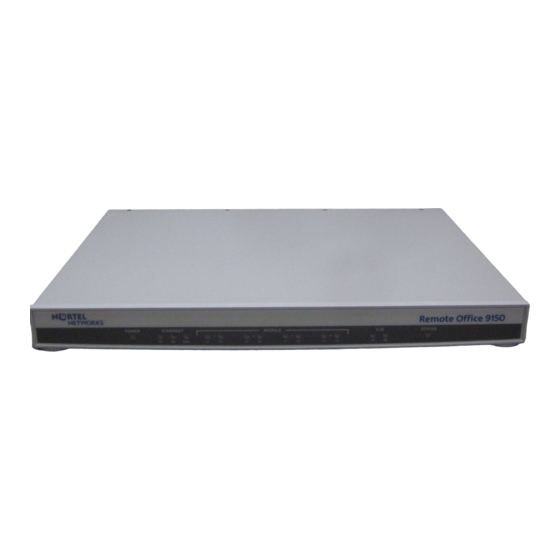
Remote Office 9150 hardware description Introduction The Remote Office 9150 unit is installed in your office and can be mounted on a desk, in a rack, or on the wall. This section describes the LED displays, power supply, cables, and connectors for the unit. - Page 40 Remote Office 9150 description Standard 1.0 The operational status of the Remote Office 9150 unit is indicated by these LEDs as described in the following table. LED type LED name Description Power When lit, this LED indicates that power is present.
- Page 41 Refer to Chapter 2, “Planning for installation,” for a detailed description of cables and connectors. Mounting options The Remote Office 9150 unit can be mounted on a desk, in a rack, or on the wall. Universal power supply The Remote Office 9150 unit includes an auto-sensing 110/220 V power supply that is compatible with commercially available UPS systems.
- Page 42 Remote Office 9150 description Standard 1.0 Remote Office 9150 power supply T E L C Remote Office 9150 E T H E R N T E L P O W A D M V . 3 5 Remote Office 9150...
-
Page 43: Add-On Modules Description
BRI U or S/T interfaces, and up to three DSP application modules. Optional trunk interface modules The Remote Office 9150 unit can support up to four U or S/T ISDN BRI interfaces. Each module supports one ISDN BRI line (with two B-channels) from the local telephone service provider. - Page 44 In addition, you can configure the Remote Office 9150 unit for blocking with only enough modules to support the maximum number of simultaneous calls. For example, a Remote Office 9150 unit that is equipped with a single DSP application module supports 16 simultaneous calls, for a ratio of 2:1 blocking.
-
Page 45: Connection Options
QoS transitioning technology automatically moves the calls back to the IP network. The Remote Office 9150 unit monitors the QoS on the IP network. If the QoS falls below preprogrammed acceptable thresholds, calls are dynamically and transparently switched to the ISDN BRI lines. - Page 46 Remote Office 9150 description Standard 1.0 Analog port for fax machines The Remote Office 9150 unit has one analog port that you can use as a fax connection. See “Fax support” on page 59 for more detailed information. Remote Office 9150...
-
Page 47: How The Remote Office 9150 Unit Works
These two components, along with the connection options described on page 19, extend the host PBX services to users in your office. Network diagram The following diagram shows a MIG RLC and Remote Office 9150 network. Remote site 1: Branch office Up to 32 digital telephones... - Page 48 When a user places a call through the host PBX to a user at the Remote Office 9150 site, a connection is made from the MIG RLC to the Remote Office 9150 unit and the host PBX completes the call normally. If a connection cannot be established, then the call rings until it is forwarded to voice mail by the host PBX.
- Page 49 When a user places a call to someone at the host site, or when someone from the host site calls the Remote Office 9150 site, the call is in host-controlled call mode. Calls in host-controlled mode are routed through the host PBX. See the sample illustrations on pages 24 and 26.
- Page 50 The network that is used to route the host-controlled call is transparent to the user, and the dialing requirement is the same for both. Calls work the same way in reverse, from host PBX site to the Remote Office 9150 site. Remote Office 9150...
- Page 51 User 1 dials a telephone number (such as the extension number of host station 1). Result: The dialed digits are sent by the Remote Office 9150 unit as packets across the Ethernet network. The MIG RLC converts the packets to the format required by the PBX.
- Page 52 The network used to route the call is transparent to the user, and the dialing requirement is the same for both. Calls work the same way in reverse, through the host PBX site to the Remote Office 9150 site. Remote Office 9150...
- Page 53 MIG RLC over the IP network was successful. User 1 dials the external telephone number. Result: The dialed digits are sent by the Remote Office 9150 unit as packets across the Ethernet network. The MIG RLC converts the packets to the format required by the PBX.
- Page 54 Remote Office 9150 description Standard 1.0 Call scenario 3: local-controlled mode—local call The following diagram shows how a call is routed when making a call within your local area. Local-controlled call Branch office Up to 32 digital telephones (Chicago) User 1...
- Page 55 March 2000 Remote Office 9150 description Local call User 1 presses the local call appearance key and hears a dial tone from the Remote Office 9150 unit. User 1 then dials a trunk access code (such as #61) and hears a dial tone from the Central Office (PSTN).
- Page 56 Remote Office 9150 description Standard 1.0 Remote Office 9150...
-
Page 57: Section B: Feature Description
March 2000 Remote Office 9150 description Section B: Feature description In this section Overview System security Trunking, connection types, and call timers Telephones Voice over IP features Port management Station priority Connection bandwidth Local calling Online/offline table Other supported features... -
Page 58: Overview
The Remote Office 9150 unit supports three security levels—no security, calling line identification (CLID), and security identifier. The security levels control access from the Remote Office 9150 unit to the MIG RLC on the host PBX. Trunking The Remote Office 9150 unit automatically allocates trunk bandwidth as it is needed. -
Page 59: Port Management
Remote Office 9150 description Call on demand versus permanent connections The ISDN connection between the MIG RLC and Remote Office 9150 unit can be a permanent or call on demand connection. The connection type is defined on the MIG RLC port to which the Remote Office 9150 unit is assigned. - Page 60 For more details, see “Station priority” on page 52. Local calling The Remote Office 9150 unit allows you to place calls to other extensions within your office, or to telephones in your local community. This is accomplished through the use of up to two local call appearance keys.
- Page 61 PSTN line. If you make an emergency service call from a station that is connected to the Remote Office 9150 unit, the call is routed through the host PBX, which could be in a different city.
-
Page 62: System Security
Introduction This section describes the security levels that are supported for controlling access from the Remote Office 9150 unit to the MIG RLC on the host PBX. No security When no security measures are used, the MIG RLC accepts all incoming calls from the Remote Office 9150 site. - Page 63 MIG RLC port to which the Remote Office 9150 unit is assigned. If the identifiers match, access is granted. If the identifiers do not match, an event is recorded in the Remote Office 9150 unit system log, which can be viewed in Configuration Manager. The telephone that was used to make the call displays a message indicating that communications with the host PBX are down.
-
Page 64: Trunking, Connection Types, And Call Timers
Connection types The Remote Office 9150 connection to the MIG RLC can be defined on the MIG RLC as a permanent or demand connection. A permanent connection means that the ISDN connection to the host PBX always remains open. A demand connection means that the ISDN connection opens only when a connection with the host PBX is required. - Page 65 March 2000 Remote Office 9150 description Minimum call duration timer Most ISDN tariffs specify a minimum length of time for which you are charged when you open the line, regardless of the call duration. This is the same as the minimum call charges listed on long distance telephone bills.
- Page 66 Remote Office 9150 description Standard 1.0 Example 2 If the call lasts for 65 seconds and no other calls are made, the ISDN connection drops after another 60 seconds has passed without activity. Since the ISDN call exceeded 59 seconds, the minimum call duration timer no longer applies. The idle timer is used, in this case, to prevent further ISDN charges.
-
Page 67: Telephones
March 2000 Remote Office 9150 description Telephones Introduction This section lists the telephones, features, and modules supported by the Remote Office 9150 unit. Supported digital telephones The following Meridian digital telephones are supported: M2008D M2616CT M3902 M2008HFD M3110 M3903 M2216D... - Page 68 Conference Call Forward ACD features Paging See Chapter 6, “Using Remote Office 9150 stations,” for a detailed description of the above features. Computer telephony integration applications There are two types of computer telephony integration (CTI) applications: first-party CTI applications that use the Symposium Desktop TAPI Service...
- Page 69 March 2000 Remote Office 9150 description You can use first-party CTI applications with the Remote Office 9150 unit if your PC is equipped with a Symposium Communicator card version 1.2 with software version 2.0 your digital telephone is equipped with a Meridian Communications Adaptor (MCA) Note: The Symposium Communicator Card is not available in all countries.
-
Page 70: Voice Over Ip Features
Standard 1.0 Voice over IP features Introduction You can configure the Remote Office 9150 unit to use the following Voice over IP features: Convert analog voice into digital data for transmission as voice packets over the network for calls to or from the fax machine or other analog device that is connected to the analog port on Telco 1. - Page 71 IP network to the circuit-switched network when the voice QoS falls below a predetermined threshold. Both the MIG RLC and the Remote Office 9150 unit monitor the IP network’s QoS constantly. If the IP network QoS degrades, causing poor voice quality, the Remote Office 9150 unit moves, or transitions, the call to the circuit-switched network.
- Page 72 G101427 The following table describe the threshold and duration settings shown in the diagram. These settings are configured on the MIG RLC port to which the Remote Office 9150 unit is assigned. Setting Description Represents the threshold representing acceptable signal quality on the IP network.
- Page 73 Office 9150 unit establishes a PSTN network connection to the MIG RLC on the host PBX. The Remote Office 9150 unit can make multiple PSTN connections (one every 30 seconds) depending on the bandwidth required to service all currently active calls.
- Page 74 IP network and all new calls are placed over the IP network. Quality of Service traffic measurements As each voice packet is sent over the IP network, the Remote Office 9150 unit monitors the following QoS parameters:...
- Page 75 Remote Office 9150 description Offline IP network measurements Once the Remote Office 9150 unit has reverted to using its PSTN connections, it must continually monitor the IP network to determine an appropriate time to restore voice traffic to the IP network as follows: Pseudo voice traffic is placed on the IP network by both the MIG RLC and the Remote Office 9150 unit.
-
Page 76: Port Management
Remote Office 9150 description Standard 1.0 Port management Introduction You can assign Remote Office 9150 stations to one of the following types of MIG RLC ports: single-user ports multi-user voice ports dynamic port pool Port types are assigned on the MIG RLC. Refer to the Meridian Internet Gateway Reach Line Card Installation and Administration Guide (NTP 555-8421-210) for detailed instructions. - Page 77 March 2000 Remote Office 9150 description Dynamic port pool Dynamic port pooling is similar to a multi-user port except that the persons who share ports in a dynamic pool are assigned to the next available port in the MIG RLC port pool. There is no correlation between the station and the port on the MIG RLC.
-
Page 78: Station Priority
Calls transition between the IP and circuit-switched networks whenever voice QoS levels change. (The voice QoS levels are defined on the Quality of Service screen on the MIG RLC for your Remote Office 9150 unit.) - Page 79 March 2000 Remote Office 9150 description The number of stations that can be configured as high priority depends on the amount of available bandwidth. Ensure that enough bandwidth is available to process calls on normal priority stations. IP only Calls to and from the station are routed over the IP network only (if the IP network is used to route calls).
-
Page 80: Connection Bandwidth
Standard 1.0 Connection bandwidth Introduction On the connection between the MIG RLC and the Remote Office 9150 unit, you can configure the following: when to open additional B-channels (referred to as extra bandwidth) how much bandwidth to reserve for high priority stations (referred to as priority reserved bandwidth) For instructions, refer to “Configuring ports”... -
Page 81: Local Calling
When you place a call to another telephone in your office using the local call appearance key, it is handled by the Remote Office 9150 unit, not the host PBX. Note: If the call is initiated from the host call appearance key, then the station-to-station call requires transmission of signaling data through the host PBX. - Page 82 Remote Office 9150 description Standard 1.0 Telephone features that are supported The following Meridian telephone features are supported for local-controlled calls: Paging Call Waiting Hold for calls that appear on local call appearance keys Call Transfer (blind and announced) for station-to-station calls only...
-
Page 83: Online/Offline Table
You can define each entry as online, offline, or undefined for each time period entered. Users at the Remote Office 9150 site can override the settings of the online/ offline table, should the table attempt to suspend access to the host PBX in the middle of a business call. - Page 84 Refer to the Meridian Internet Gateway Reach Line Card Installation and Administration Guide (NTP 555-8421-210) for configuration information. For a description of how to go online or offline at the Remote Office 9150 site, see Chapter 6, “Using Remote Office 9150 stations.”...
-
Page 85: Other Supported Features
Fax support The Remote Office 9150 unit contains one analog port that can be used to send and receive faxes. Faxes can be sent and received in both host- and local- controlled call modes over the IP or circuit-switched network. Faxes are sent uncompressed (that is, 64 Kbps of bandwidth is required). - Page 86 PSTN line. If you make an emergency service call from a station that is connected to the Remote Office 9150 unit, the call is routed through the host PBX, which could be in a different city.
-
Page 87: Administration Software
The software is provided on the Remote Office Product CD-ROM. You can also obtain it from the Nortel Networks web site. Administration PC connection options You can connect the administration PC to the Remote Office 9150 unit through the following: an RS-232 connection to the administration PC’s serial port... -
Page 88: Command Line Interface
Standard 1.0 Command line interface When the administration PC is connected to the Remote Office 9150 unit through the serial port, you can view the command line interface using an application such as Telnet or HyperTerminal. However, the command line interface is not documented in this guide. -
Page 89: Planning For Installation
C h a p t e r 2 Planning for installation In this chapter Overview Installation checklist Physical environment Administration PC Network considerations Managing trunk connections Station configuration Security Planning for future growth Deployment options Planning the configuration Installation and Administration Guide... -
Page 90: Overview
The Remote Office 9150 unit communicates through both the IP and the telecommunications networks using a Meridian 1 PBX. To use the Remote Office 9150 unit in these networks, you must consider the issues described in this chapter. Remote Office 9150... - Page 91 Trunk management You can manage connections to the host PBX in several ways: Put the Remote Office 9150 unit into offline mode so that it cannot receive or make calls through the host PBX. Define a trunk connection as permanent or on-demand.
- Page 92 Planning for installation Standard 1.0 Deployment options The MIG RLC on the host PBX and Remote Office 9150 unit can be installed and configured to initially use only the IP network (Voice over IP) only the circuit-switched network (for example, ISDN BRI trunks)
-
Page 93: Installation Checklist
If you want to use the circuit-switched “ISDN BRI information” on page network to route calls, order trunks from the 102. central office to the Remote Office 9150 unit site. Note: The Remote Office 9150 unit supports ISDN BRI trunks (S/T or U interface). - Page 94 Choose a suitable location for the Remote “Choosing a suitable location” Office 9150 unit. on page 122. Install the Remote Office 9150 unit in the “Mounting the Remote Office chosen location. 9150 unit” on page 122. Connect the Remote Office 9150 unit to the “Connecting the Remote Office...
- Page 95 MIG RLC’s telephone number primary trunk security level and, if required, security identifier Ping the Remote Office 9150 unit and ensure “Testing the network that it is recognized as a device on the connections” on page 155. network.
- Page 96 Planning for installation Standard 1.0 Remote Office 9150 unit Installation checklist Page 4 of 4 Check Task For details, see Configure network devices your data network administrator. so that voice traffic is not constrained or congested Appendix A, “Network engineering guidelines”...
-
Page 97: Physical Environment
Remote Office 9150 unit. Space Ensure that the Remote Office 9150 unit is installed in a location that is dry and provides plenty of air circulation. The chosen location should be within cable-length distance from the following:... - Page 98 Storage Recommended temperature -20°C (-4°F) 60°C (140°F) Relative humidity 95% (non-condensing) Non-condensing -40°C (-40°F) 70°C (158°F) Temperature shock In 3 minutes -40°C (-40°F) 25°C (77°F) In 3 minutes 70°C (158°F) 25°C (77°F) Non-condensing -40°C (-40°F) 70°C (158°F) Remote Office 9150...
- Page 99 March 2000 Planning for installation Mounting options You can place the Remote Office 9150 unit on a desk or in a rack, or you can mount it on the wall. The Remote Office 9150 unit dimensions are 42.5 cm (17 in.) wide (without rack-mounting brackets) 29.4 cm (11.75 in.) deep...
- Page 100 Notes: In North America, the power cord and power supply are included inside the Remote Office 9150 box. In all other regions, the power supply is provided inside the box. However, the power cord for your region is provided outside the box.
- Page 101 Remote Office 9150 unit. Ethernet cable If you are connecting the Remote Office 9150 unit to a hub, you need a standard CAT5 unshielded twisted-pair (UTP) straight-through Ethernet cable. The cable should be no longer than 100 meters (325 feet) in length.
-
Page 102: Administration Pc
Serial connection You must use the serial connection when you first install and configure the Remote Office 9150 unit. You must establish a serial connection to the Remote Office 9150 unit to enter the IP interface information. See the following diagram. - Page 103 Planning for installation You can continue using the serial connection for ongoing administration of the Remote Office 9150 unit, if you wish. However, if this is the only connection option used, you cannot administer the Remote Office 9150 unit remotely or perform upgrades.
- Page 104 If you are responsible for administering one or more Remote Office 9150 units and the MIG RLC on the host PBX, you can access the Remote Office 9150 unit and the MIG RLC from anywhere on the network. The following diagram shows an example of an assembled network with administration PCs.
- Page 105 Internet. Year 2000 compliance The Remote Office 9150 unit and Configuration Manager software are Year 2000 compliant. However, you must ensure that the administration PC is Year 2000 compliant by verifying that the Windows operating system is listed in this...
- Page 106 Meridian Administration Tools (MAT) and Configuration Manager are not guaranteed to operate simultaneously on the same administration PC. Simultaneous operation of these two applications on the same PC has not been tested and therefore, is not supported. Remote Office 9150...
-
Page 107: Network Considerations
The Remote Office 9150 unit communicates through both the IP and telecommunications network using a Meridian 1 PBX. To use the Remote Office 9150 unit in these networks, you must consider the issues described in this section. IP addressing and routing... -
Page 108: Quality Of Service
Planning for installation Standard 1.0 Network diagram The following diagram shows the Remote Office 9150 unit’s position in an IP network. Internal M1 Meridian 1 Ethernet Ethernet network network network Remote Office 9150 Router 10.1.1.2 10.3.1.1 COLL V.35 10.2.1.10 10.4.1.2 10.3.1.2... - Page 109 Planning for installation Numbering plans Each trunk groups at the Remote Office 9150 unit site must be assigned a trunk access code (that is, the number dialed to obtain an outgoing trunk). In addition, special prefix (SPRE) codes must be defined for the following features if you...
- Page 110 DSP application modules can be installed in the Remote Office 9150 unit, allowing 32 active calls at one time. Note: If you add DSP capacity to the Remote Office 9150 unit, you must add the same DSP capacity to the MIG RLC on the host PBX.
-
Page 111: Managing Trunk Connections
Managing trunk connections Introduction You can manage trunk connections to the host PBX in several ways: Put the Remote Office 9150 unit into offline mode, so that it cannot receive or make calls through the host PBX when operating in circuit-switched mode. - Page 112 Remote Office 9150 unit can make and receive calls through the host PBX. When the Remote Office 9150 unit is in offline mode, calls cannot be made or received through the host PBX over the IP or circuit-switched network.
- Page 113 Planning for installation Trunk connection type and timers On the Remote Office 9150 unit, you can define each trunk as a permanent or on-demand connection. When the trunk is defined as an on-demand connection, the trunk is activated only when a call is received from the host PBX, or initiated by a user at the Remote Office 9150 site.
-
Page 114: Station Configuration
Port allocation Assign each user at the Remote Office 9150 site to one port on the MIG RLC on the host PBX. You can configure MIG RLC port in one of the following ways: as a dedicated port (one port per remote user) - Page 115 When the port is configured as high priority and the priority reserved setting is configured on the connection between the MIG RLC and Remote Office 9150 unit, you can ensure voice Quality of Service for calls to and from those stations.
- Page 116 (directory) number (on local stations only) key placement (on local stations only) Port types On the Remote Office 9150 unit, you can define each station with one of the following capabilities: local control only (local) You can use stations defined as local to make and receive calls through the local PSTN.
- Page 117 User extension configuration Each station is assigned a local directory number (DN). The Remote Office 9150 unit uses the DN to route the incoming call to the correct station. Stations that are configured with host-controlled call capability are associated with a port number on the MIG RLC.
-
Page 118: Security
You can use security identifier authentication over the IP or circuit- switched network. If this level is chosen, a security identifier must be configured on both the Remote Office 9150 unit and the MIG RLC port to which the unit is assigned. When a connection between the host PBX and Remote Office 9150 unit is attempted, the security identifiers are compared. -
Page 119: System Configuration
March 2000 Planning for installation Data network security The Remote Office 9150 solution does not provide for data network security. If security on the data network is an issue, security must be implemented on the data network devices. System configuration... -
Page 120: Planning For Future Growth
Adding DSP modules The Remote Office 9150 unit ships with the ability to support up to 32 stations (which must all be assigned to one MIG RLC). Up to eight simultaneous voice calls can be supported when calls are routed over the IP network. - Page 121 Planning for installation Adding trunk interface modules Initially, the Remote Office 9150 unit ships with no trunks. As connection needs change, you can add up to four ISDN BRI S/T or U trunk interface modules. To determine how many trunk interface modules you need to install, use the “Remote Office 9150 System expansion worksheet”...
- Page 122 Standard 1.0 Component Maximum MCAs or ATAs (continued) Notes: You can have eight MCAs or ATAs installed if an analog telephone or fax machine is not installed. The total number of digital telephones and ATAs cannot exceed 32. Remote Office 9150...
-
Page 123: Deployment Options
MCAs for data transmission to ports that are configured on the host PBX with data capability. If the circuit-switched network will be used to route calls, one data port on the host PBX must be dedicated to the Remote Office 9150 site to establish the call connections. Installation and Administration Guide... - Page 124 Install ISDN BRI trunk interface and DSP application modules on the Remote Office 9150 unit, if needed. Up to four ISDN BRI modules and up to three DSP application modules can be installed. Similarly, install DSP application modules on the MIG RLC, if needed.
- Page 125 Similarly, obtain the telephone number assigned to the MIG RLC port to which this Remote Office 9150 unit is assigned. This telephone number must be configured on the Remote Office 9150 unit, and is used by the Remote Office 9150 unit to establish connections with the MIG RLC.
- Page 126 Standard 1.0 Similarly, obtain the IP address assigned to the MIG RLC. This IP address must be configured on the Remote Office 9150 unit, and is used by the Remote Office 9150 unit to establish connections with the MIG RLC.
-
Page 127: Planning The Configuration
You must assign each telephone in your office to one of the 32 ports provided by the Remote Office 9150 unit. You can configure stations with the ability to make local-controlled calls (local), host-controlled calls (remote), or both (local and remote). - Page 128 ISDN BRI information Providing information to your service provider To ensure that you get the correct ISDN service for the Remote Office 9150 unit, tell your service provider how the ISDN line should be provisioned. Request the following: two B-channels providing voice and data capability Both B-channels must be Circuit Switched Voice and Data.
- Page 129 March 2000 Planning for installation IP addresses If you want to administer the Remote Office 9150 unit over the IP network, the following information is required for the Remote Office 9150 unit: IP address (it must be unique) subnet mask...
- Page 130 “Meridian Internet Gateway Reach Line Card Online/Offline Table Configuration” form on page 457. Trunk configuration information Trunk configuration on the Remote Office 9150 unit consists of defining the ISDN BRI lines from the central office and assigning one or more B-channels, if desired, to trunk groups.
-
Page 131: Installing The Remote Office 9150 Unit
Overview General safety Required tools Unpacking and inspecting the equipment Removing the Remote Office 9150 unit cover Installing a trunk interface or DSP application module Mounting the Remote Office 9150 unit Connecting the Remote Office 9150 unit Powering up the Remote Office 9150 unit... -
Page 132: Overview
Installing the Remote Office 9150 unit Standard 1.0 Overview Introduction This chapter explains how to install the Remote Office 9150 unit in your office. Safety This document contains general safety guidelines that are recommended by Nortel Networks. You must follow these safety guidelines whenever you perform installation or maintenance tasks on the Remote Office 9150 unit. -
Page 133: Software Configuration
Software configuration The Configuration Manager software is used to configure and administer the Remote Office 9150 unit. This software is located on the CD-ROM provided in the package. You must install the software on the administration PC. After the software is installed, you must... -
Page 134: General Safety
Safety precautions To avoid damage or injury, follow these safety precautions at all times. Plug the Remote Office 9150 unit into a properly grounded power source to reduce the possibility of electric shock and damage to the unit or network. - Page 135 March 2000 Installing the Remote Office 9150 unit Electrostatic discharge safety precautions Electrostatic discharge (ESD) affects the performance and decreases the useful life of system components. ESD can seriously damage component parts, such as circuit cards. Implement the following precautions, which are recommended by computer and telephone equipment manufacturers: Remove items that generate static charge from the installation site.
-
Page 136: Required Tools
This section identifies the tools you need to perform Remote Office 9150 unit installation and maintenance tasks. Hardware installation tools You need the following tools to install the Remote Office 9150 unit, or to install or replace DSP application or trunk interface modules: an antistatic ESD wrist strap (recommended) -
Page 137: Unpacking And Inspecting The Equipment
Installing the Remote Office 9150 unit Unpacking and inspecting the equipment Introduction Before you install the Remote Office 9150 unit, ensure that the package contents are all present and are not damaged. Before you begin Before you unpack the equipment, ensure that your work area is safe from electrostatic discharge. - Page 138 Install DSP application and trunk interface modules, if required. For instructions, see “Installing a trunk interface or DSP application module” on page 116. Install the Remote Office 9150 unit in its chosen location. For instructions, see “Mounting the Remote Office 9150 unit” on page 122. Remote Office 9150...
-
Page 139: Removing The Remote Office 9150 Unit Cover
9150 unit, you need to perform one or more of the following tasks: Install additional trunk interface modules. Install additional DSP application modules. To perform these tasks, you must remove the Remote Office 9150 unit cover. To remove the Remote Office 9150 unit cover DANGER... - Page 140 Installing the Remote Office 9150 unit Standard 1.0 Removing the screws Remote Office 9150 (Top view) P O W E T H E R N CO LL M O D U L E V .3 5 S T A T U S...
- Page 141 Lift the cover off the unit. d. Put the cover aside. Turn the Remote Office 9150 unit so the rear panel faces you. This allows you to read the labels on the Remote Office 9150 unit circuit board. Perform module installation as required.
-
Page 142: Installing A Trunk Interface Or Dsp Application Module
DSP application modules convert voice and fax into digital data for transport over the IP and circuit-switched networks. Initially, the Remote Office 9150 unit ships with the ability to support up to eight simultaneous calls through a DSP that is built into the Remote Office 9150 unit’s motherboard. - Page 143 Ensure that you follow the electrostatic discharge safety precautions described on page 109. Where the modules can be installed Each module position is labeled on the Remote Office 9150 unit circuit board as shown in the following table: Module type...
- Page 144 Note: Each Telco connector provides access to two ISDN BRI lines (each with two B-channels). The following diagram shows where you can install the trunk interface and DSP application modules on the Remote Office 9150 unit circuit board: Trunk interface modules Telco 2...
- Page 145 Gently lift one side of the module up until it is free of the connectors on the Remote Office 9150 unit circuit board. Lift the module up and away from the Remote Office 9150 unit circuit board, and place it to one side.
- Page 146 Use both hands to grasp the module firmly and push down until it snaps into place. Visually inspect the module connectors to ensure there is no gap between the module connectors and the Remote Office 9150 motherboard connectors. Ensure the module is securely installed by placing one finger beneath the module and tugging upward.
- Page 147 What’s next? After you have installed the trunk interface or DSP application modules, replace the Remote Office 9150 unit cover, and then install the unit in its chosen location. For instructions, see the following: “To replace the Remote Office 9150 unit cover” on page 115 “Mounting the Remote Office 9150 unit”...
-
Page 148: Mounting The Remote Office 9150 Unit
Remote Office 9150 unit on a desk brackets with screws for installing the Remote Office 9150 unit in a rack If you want to mount the Remote Office 9150 unit on a wall, you must provide your own mounting hardware. - Page 149 Installing the Remote Office 9150 unit To install the Remote Office 9150 unit on a desk Turn the Remote Office 9150 unit bottom side up. Affix the rubber feet to the Remote Office 9150 unit as shown in the following diagram: Peel off...
- Page 150 Standard 1.0 To install the Remote Office 9150 unit on the wall Do not affix the rubber feet to the bottom of the Remote Office 9150 unit. Otherwise, the unit cannot be mounted flush against the wall. To mount the Remote Office 9150 unit on the wall, you must provide your own screws.
- Page 151 Choose the location on the wall where you want to mount the Remote Office 9150 unit. Use the predrilled screw slots on the bottom of the Remote Office 9150 unit as a guide to measure and mark the location on the wall for each mounting screw.
- Page 152 Note: Two sets of screw slots are provided. Each set allows you to route the cables to the left or right when the Remote Office 9150 unit is correctly mounted. Ensure you use the same screw slot orientation for each location that you mark on the wall.
- Page 153 Attach the rack-mount brackets as shown in the following illustration. T E L C E T H E R N T E L P O W A D M V . 3 5 G101397 Slide the Remote Office 9150 unit into the rack slot. Installation and Administration Guide...
- Page 154 “Connecting the Remote Office 9150 unit” on page 129. What’s next? When you have completed the installation of the Remote Office 9150 unit in its chosen location, attach the cables. For instructions, see “Connecting the Remote Office 9150 unit” on page 129.
-
Page 155: Connecting The Remote Office 9150 Unit
When you establish the cabling connections, you are connecting the Remote Office 9150 unit to the power source telephones and ISDN BRI trunks Note: If you are connecting the Remote Office 9150 unit to a Meridian 1 in-building cross-connect system, you need a QCBIX1A BIX block. Ethernet network administration PC... -
Page 156: More Information
Standard 1.0 Ethernet cable If you are connecting the Remote Office 9150 unit to a hub, you need a standard CAT5 unshielded twisted-pair (UTP) straight-through Ethernet cable. The cable should be no longer than 100 meters (325 feet) in length. - Page 157 March 2000 Installing the Remote Office 9150 unit Remote Office 9150 unit connection panel The following diagram shows the connectors on the back panel of the Remote Office 9150 unit. T E L C E T H E R N...
- Page 158 Installing the Remote Office 9150 unit Standard 1.0 Wall-mount cable attachment If you mounted the Remote Office 9150 unit on the wall, the following diagram shows cable attachment. Cables must be connected and routed away from the 9150 unit at a right angle...
- Page 159 If you want to route calls over the IP network, or administer the Remote Office 9150 unit from another location on the IP network, connect the Remote Office 9150 unit to the Ethernet network by doing the following: a. Connect one end of the RJ-45 Ethernet cable to the ETHERNET connector on the Remote Office 9150 unit.
- Page 160 Installing the Remote Office 9150 unit Standard 1.0 Connect the ADMIN connector on the Remote Office 9150 unit to the administration PC as follows: a. Connect the male 9-pin connector of the supplied RS-232 serial cable to the ADMIN connector on the Remote Office 9150 unit.
-
Page 161: Powering Up The Remote Office 9150 Unit
Installing the Remote Office 9150 unit Powering up the Remote Office 9150 unit Introduction As soon as you connect the Remote Office 9150 unit to the power source, the unit begins to power up. What happens during power-up During power up, the following events occur: The Remote Office 9150 unit performs a self-test that verifies all critical functionality. - Page 162 All LEDs except the Status LED go out. The Status LED remains lit. Note: Steps 2 through 4 take about 4 to 5 seconds. After this point, the Remote Office 9150 unit is functional. Notes: The ETHERNET TX and RX and module (ISDN BRI) LEDs flash only when transmit and receive activity is present on those interfaces.
- Page 163 Continue with “Installing the software” on page 138. If the power-up cycle was not successful (indicated by the Status LED going out), contact your Nortel Networks distributor. There is a possible hardware problem. Installation and Administration Guide...
-
Page 164: Installing The Software
Introduction You use the Configuration Manager software to configure and administer the Remote Office 9150 unit. This software is located on the CD-ROM provided in the package. You must install the software on the administration PC. To install the software Insert the CD-ROM in the applicable drive on your PC. - Page 165 March 2000 Installing the Remote Office 9150 unit Click Next, and then follow the screen prompts. Result: Once the software has been installed, messages appear confirming that the Windows registry has been updated and that the installation was successful. Click OK to both messages.
- Page 166 Installing the Remote Office 9150 unit Standard 1.0 For instructions, see “Using the Configuration Wizard to perform initial configuration” on page 141. Note: DLL files installed by the Configuration Manager InstallShield should be left in the Windows system directory. Do not move these files to any other directory.
-
Page 167: Using The Configuration Wizard To Perform Initial Configuration
The Configuration Wizard option in Configuration Manager allows you to configure the minimum information needed for establishing communications between the Remote Office 9150 unit and the MIG RLC at the host site. The Configuration Wizard does not provide all the configuration settings that are available in Configuration Manager. - Page 168 Installing the Remote Office 9150 unit Standard 1.0 Note: If, after completing configuration with the Configuration Wizard, you want to modify any settings, you must use Configuration Manager. To start Configuration Manager Click Start Programs Remote Office Configuration Manager. Result: The Configuration Manager opens and you are prompted for the logon name and password.
- Page 169 March 2000 Installing the Remote Office 9150 unit Type admin into the Login Name box. Type root into the Password box. Note: This is the default password. It might be different. Click OK. Result: You are informed if the logon was successful.
- Page 170 Installing the Remote Office 9150 unit Standard 1.0 Enter the COM port to which the Remote Office 9150 unit is connected, and then click OK. Result: The User Authentication for Serial Mode dialog box appears. Type guest for the logon name.
- Page 171 March 2000 Installing the Remote Office 9150 unit Click OK. Result: The connection attempt is initiated. Trying to Connect via Serial Port <port number> might appear. IF the logon attempt THEN failed the following message appears: SERIAL CONNECTION FAILED Check the serial connection and ensure it is good.
- Page 172 Installing the Remote Office 9150 unit Standard 1.0 IF the logon attempt THEN succeeded When initialization is completed, the following (continued) dialog box appears: Click OK. Continue with “To perform configuration with the Configuration Wizard.” To perform configuration with the Configuration Wizard Note: The screen examples in this procedure use information from the sample network diagram in “Example of a network”...
- Page 173 Set the unique Unit ID of the Enter the number from 1–255 that uniquely unit identifies the Remote Office 9150 unit you are configuring for a particular MIG RLC. Note: Each unit connected to a MIG RLC must be given a unique unit ID. This implies...
- Page 174 255.255.0.0. Enter the Local IP Gateway Enter the IP address of the gateway of the unit between the Remote Office 9150 unit and the network. Note: If there is no router between the Remote Office 9150 unit and the network, then the administration PC acts as the gateway.
- Page 175 March 2000 Installing the Remote Office 9150 unit Click Next. Result: The Set the Configuration for the Remote Unit screen appears. Note: A completed example is shown on page 150. Complete the fields on this screen as described in the following table:...
- Page 176 Installing the Remote Office 9150 unit Standard 1.0 Field Description Wish to configure Multiple Click Yes if you want to assign Remote 9150 Ports Office 9150 ports to digital telephones now. Then, do the following: Enter the first MIG RLC port number to assign.
- Page 177 Remote Office 9150 unit. Module Status This box identifies if a module has been physically installed on the Remote Office 9150 unit. Select the Select the type of switch used by your ISDN Switch Type service provider.
- Page 178 Installing the Remote Office 9150 unit Standard 1.0 The following is a completed example. Select the module you want to configure. Specify the ISDN line and switch type. (Get this information from your service provider.) Enter the DN and SPID for each B-channel.
- Page 179 3 on page 147. The information in this file can be opened in Configuration Manager, and then sent to and saved in the Remote Office 9150 unit’s flash memory at another time. For instructions, refer to “Working with configuration files” on page 183.
- Page 180 Installing the Remote Office 9150 unit Standard 1.0 What’s next? Now that you have configured the minimum information required for network connectivity, you can do the following: Test the network connections. For instructions, see “Testing the network connections” on page 155.
-
Page 181: Testing The Network Connections
To test the Ethernet connection between the administration PC and the Remote Office 9150 unit, you can use PING. To do this test, the Remote Office 9150 unit and the administration PC must be physically connected to the IP network. - Page 182 Installing the Remote Office 9150 unit Standard 1.0 The following is an example of a successful ping: The following is an example of an unsuccessful ping: Click Close. Result: The Ping test screen closes. Remote Office 9150...
- Page 183 Look at the digital telephone display. Does it display the correct time and date? If yes, then the connection paths between the digital telephone, Remote Office 9150 unit, and the MIG RLC are working. Lift the telephone handset, or press the host call appearance key to go off hook.
- Page 184 MIG RLC, if the circuit-switched network is being used to route calls the security IDs of both the Remote Office 9150 unit and the MIG RLC, if a security ID is required to authenticate connection attempts...
- Page 185 Installing the Remote Office 9150 unit What’s next? Once you have confirmed that the Remote Office 9150 unit can be recognized on the network, you can fine-tune the configuration. Nortel Networks recommends that you also change the passwords used for logging on to the Configuration Manager and the Remote Office 9150 unit.
- Page 186 Installing the Remote Office 9150 unit Standard 1.0 Remote Office 9150...
-
Page 187: Configuration Manager Overview
C h a p t e r 4 Configuration Manager overview In this chapter Overview Starting Configuration Manager Configuration Manager description Using the online Help Configuration files description Working with configuration files Selecting the device type for offline configuration Logging on to a unit Logging off from a unit Performing a system restart or shutdown Closing Configuration Manager... -
Page 188: Overview
Configuring a unit You can configure a unit (that is, a Remote Office 9150 unit or MIG RLC) in one of two ways: Connect to, and then log on to the unit by serial port or Telnet (which requires Ethernet network connectivity). - Page 189 March 2000 Configuration Manager overview You can update the unit’s flash memory by using one of the following methods: Open the configuration file within Configuration Manager, click Send, and then save it to flash. Initiate an upload from your PC to the unit’s flash memory by using the configuration upload option in the Configuration Manager menu.
-
Page 190: Starting Configuration Manager
To perform administrative tasks, you must first start the Configuration Manager software. To start Configuration Manager Click Start Programs Remote Office Configuration Manager. Result: The Configuration Manager opens and you are prompted for the logon name and password. Remote Office 9150... - Page 191 March 2000 Configuration Manager overview Type admin in the Login Name box. Type root in the Password box. Note: This is the default password. It might be different. Click OK. Result: You are informed if the logon was successful. Click OK. Result: The Login Name dialog box disappears.
- Page 192 Configuration Manager overview Standard 1.0 Remote Office 9150...
-
Page 193: Configuration Manager Description
March 2000 Configuration Manager overview Configuration Manager description Introduction This section describes each part of the Configuration Manager screens. Parts of the Configuration Manager screen The Configuration Manager is divided into three parts— a menu and two panes. The menu across the top of the screen lists various administrative tasks you can perform. -
Page 194: Property Sheets
Tree Bar again. Property sheets When you are logged on to a particular system (that is, a Remote Office 9150 unit or MIG RLC), and you click an item in the system tree, the associated property sheet appears in the right pane. For instructions on selecting a device type when not logged on, see “Selecting the device type for offline... - Page 195 March 2000 Configuration Manager overview The following is an example of the property sheet associated with the 9150 System Configuration system tree option: How this guide presents instructions for displaying property sheets To simplify the procedures for accessing property sheets throughout this guide, the instructions for displaying a particular property sheet are summarized into a “Getting there”...
- Page 196 To select an item from the list, move the cursor until the desired item is highlighted, and then click the item. The item you select appears in the list box. Remote Office 9150...
- Page 197 March 2000 Configuration Manager overview In some cases, selecting a particular list item causes the property sheet contents to change as follows: Some fields appear dimmed (disabled) because they cannot be configured in the context of the list item you selected. Other fields are reenabled (no longer appear dimmed).
- Page 198 1024 by 768 pixels using Small Fonts at 96 dpi. This ensures that all fields and buttons are visible. For instructions on changing your display settings, refer to the Windows online Help on your PC. Remote Office 9150...
- Page 199 March 2000 Configuration Manager overview You can prevent these scroll bars from appearing by changing the screen area pixel and font sizes in the Windows Control Panel display settings on your PC. Command buttons The following command buttons appear on all property sheets: OK accepts any changes you make and stores them in a temporary file on your PC until you are ready to update the unit’s flash memory.
- Page 200 Help displays online Help for the property sheet you are working with. For other methods of displaying Help, see “Using the online Help” on page 175. Note: If the command buttons are not visible, use the vertical scroll bar to scroll through the screen. Remote Office 9150...
-
Page 201: Using The Online Help
March 2000 Configuration Manager overview Using the online Help Introduction While using the Configuration Manager, you might have questions about what certain boxes and buttons do, as well as how to complete certain tasks. Online Help provides brief answers to such questions. To access Help Use one of the following methods: Method 1: Click Help on the property sheet for which you need help. -
Page 202: Configuration Files Description
Configuration Wizard or Configuration Manager File Open (.TXT) File Save As or Telnet or serial Save to File (.TXT) connection (Node logon session) Send, followed by Save to Flash Event .dat Retrieve file on PC Configuration operations G101411 Remote Office 9150... - Page 203 March 2000 Configuration Manager overview Types of files There are four types of files that you can work with in Configuration Manager. Each file is identified by one of the following file name extensions as described in the following table: File name File type When it is created and used...
- Page 204 Note: You can view or edit the contents of the text file by opening it in a word processing application, such as WordPad. *.UPG Upgrade Use this file type when performing firmware upgrades. For more details, see “Performing upgrades” on page 335. Remote Office 9150...
- Page 205 March 2000 Configuration Manager overview Configuration Manager: File operations description The following table describes each operation shown in the previous diagram: Operation Description When you click OK, the following occurs: The changes you make are checked for errors. If errors are found, an error dialog box appears.
- Page 206 Data Stored to Flash dialog box appears. Note: You must perform a Send or Send All before you perform a Save to Flash. You should perform a Save to Flash as often as required. Remote Office 9150...
- Page 207 March 2000 Configuration Manager overview Operation Description Upload When you choose Upload/Download Upload Configuration Configuration from the Configuration Manager menu, the configuration file you specify is uploaded and written to the buffer on the unit to which you are connected. Use this option if you need to restore or replace an entire configuration.
- Page 208 Notes: The downloaded file is saved as a text file (.txt). The download operation does not affect the event.dat file on the PC. Therefore, if you make changes and do not save them, they are lost. Remote Office 9150...
-
Page 209: Working With Configuration Files
March 2000 Configuration Manager overview Working with configuration files Introduction This section explains how to create a configuration file (see page 184) open a configuration file in Configuration Manager (see page 185) perform a configuration upload (see page 186) perform a configuration download (see page 186) When to use the Configuration Manager file operations You can use When you are... - Page 210 Example 2: If the file contains configuration that is unique to a specific unit, enter the unit’s name or number as the file name. Ensure the Save as type box shows Text Files(*.TXT). Specify the folder where the file is to be saved. Remote Office 9150...
- Page 211 March 2000 Configuration Manager overview Click OK. Result: The file is saved. To open a configuration file Start Configuration Manager. If you want to work in online mode, log on to the unit. Otherwise, ensure that you have selected the device type. From the menu, choose File Open.
- Page 212 Click Send to update the unit, and then perform a Save to Flash. To upload a configuration to a unit For instructions, see “Restoring the configuration” on page 303. To download a configuration from a unit For instructions, see “Creating a backup configuration file” on page 301. Remote Office 9150...
-
Page 213: Selecting The Device Type For Offline Configuration
Do the following the MIG RLC Choose View Device Type RLC. the Remote Office 9150 unit Choose View Device Type 9150. Click the plus sign beside Configuration Manager in the left pane. Result: The system tree expands, showing you the types of configuration you can work with, as shown in the example on page 188. - Page 214 Configuration Manager overview Standard 1.0 System tree Remote Office 9150...
-
Page 215: Logging On To A Unit
Connection types If the MIG RLC or Remote Office 9150 unit is connected to the administration PC by the RS-232 cable, you can establish a connection through the serial port. If Ethernet connectivity has been established between the administration PC and the MIG RLC or Remote Office 9150 unit, you can establish an IP connection with Telnet. - Page 216 Enter your logon name and password, and then click OK. Result: The connection attempt is initiated. Trying to Connect to <IP address> message might appear. IF the logon attempt THEN failed the following message appears: 10060 TELNET CONNECTION FAILED Go back to step 1. Remote Office 9150...
- Page 217 March 2000 Configuration Manager overview IF the logon attempt THEN succeeded the User Logged In dialog box appears. Click OK. Result: The following dialog box appears: The following messages appear above the progress bar at the bottom of the dialog box: Reading Hardware Information Reading DSP Load Data Reading Configuration Data...
- Page 218 Enter your logon name and password, and then click OK. Result: The connection attempt is initiated. The message Trying to Connect to <IP address> message might appear. IF the logon attempt THEN failed the following message appears: 10060 TELNET CONNECTION FAILED Go back to step 1. Remote Office 9150...
- Page 219 March 2000 Configuration Manager overview IF the logon attempt THEN succeeded the User Logged In dialog box appears. Click OK. Result: The following dialog box appears: The following messages appear above the progress bar at the bottom of the dialog box: Reading Hardware Information Reading DSP Load Data Reading Configuration Data...
- Page 220 From the menu, choose Connect Login board Serial. Result: The Serial Port Configuration dialog box appears. Enter the COM port number to which the unit is connected, and then click Result: The User Authentication for Serial Mode dialog box appears. Remote Office 9150...
- Page 221 March 2000 Configuration Manager overview Enter your logon name and password, and then click OK. Result: The connection attempt is initiated. The message Trying to Connect via Serial Port <port number> might appear. IF the logon attempt THEN failed the following message appears: SERIAL CONNECTION FAILED Check the serial port connection and ensure it is good.
- Page 222 To access property sheets associated with the unit Click the plus sign beside Configuration Manager. Result: This expands the system tree. Click the name of the property sheet with which you want to work. Result: The property sheet appears in the right pane. Remote Office 9150...
-
Page 223: Logging Off From A Unit
March 2000 Configuration Manager overview Logging off from a unit Introduction When you are finished using Configuration Manager to make configuration changes, or to view logs and statistics, you should log off from the unit. Logging off secures the unit’s configuration. To log off from the unit From the menu, choose Connect Logout Board. -
Page 224: Performing A System Restart Or Shutdown
DSP application or trunk interface modules you need to power down the system for any reason To perform a system restart From the menu, choose Connect System Reset Restart. Result: The System Restart dialog box appears. Click Yes. Remote Office 9150... - Page 225 March 2000 Configuration Manager overview Result: The following status dialog box appears: The following message also appears in the status bar at the bottom of the screen: Restarting the System The status continues to show Online. When the system restart is completed, the following dialog box appears to inform you that the system restart was successful and that you were logged off: Click OK.
- Page 226 Shutting Down the System The status shows Offline. Turn the power off. Note: You must turn the power off before you can power the unit back up. Remote Office 9150...
-
Page 227: Closing Configuration Manager
March 2000 Configuration Manager overview Closing Configuration Manager Introduction When you have completed all the configuration modifications you want to make, or are done viewing unit logs and statistics, close the Configuration Manager application. This secures the configuration, preventing others from accessing it if you walk away from the administration PC while logged on to a unit. - Page 228 Configuration Manager overview Standard 1.0 Log off by choosing Connect Logout Board. From the menu, choose File Exit. Result: The Configuration Manager closes. Remote Office 9150...
-
Page 229: Configuring The Remote Office 9150 Unit
C h a p t e r 5 Configuring the Remote Office 9150 unit In this chapter Overview Section A: System settings Section B: IP addresses Section C: RLC connection information Section D: Trunk interface information Section E: Stations Installation and Administration Guide... -
Page 230: Overview
Standard 1.0 Overview Introduction This chapter describes how to configure the Remote Office 9150 unit so that it can route calls over the IP and circuit-switched networks to or from the host PBX to or from the local Public Switched Telephone Network (PSTN) -
Page 231: System Settings
The node number and name are settings that uniquely identify each Remote Office 9150 site in the telephone network. The Remote Office 9150 unit obtains its time and date from the host PBX. If the Remote Office 9150 unit is in a different time zone from the MIG RLC to which it is connected, you can configure the time zone difference. - Page 232 Configuring the Remote Office 9150 unit Standard 1.0 the Remote Office 9150 unit’s security ID (if that level of security is used) the number used to connect to the host PBX, if you are using the circuit- switched network to route calls...
- Page 233 B-channels as a group Trunk access codes Trunk access codes are numbers that are used by the Remote Office 9150 unit to determine which trunk group to use when routing the call. You must define a trunk access code for each trunk group.
- Page 234 To route calls between the host PBX and persons working at the Remote Office 9150 site, you must configure each station at the site on the Remote Office 9150 unit. Each station is associated with a port on the MIG RLC, and can be configured with different capabilities.
- Page 235 PSTN if a trunk access code was dialed before the telephone number. The Remote Office 9150 unit distinguishes an incoming call by its calling line identification (CLID), and rings it as follows:...
- Page 236 Configuring the Remote Office 9150 unit Standard 1.0 dynamic port: This is similar to a multi-user port except that the persons who share ports in a dynamic pool are assigned to the next available port in the pool. There is no correlation between the station and the port on the MIG RLC.
-
Page 237: Section A: System Settings
March 2000 Configuring the Remote Office 9150 unit Section A: System settings In this section Overview Configuring the system settings Installation and Administration Guide... -
Page 238: Overview
Time and date The Remote Office 9150 unit obtains its time and date from the host PBX. If the Remote Office 9150 unit is in a different time zone from the MIG RLC to which it is connected, you can configure the time zone difference. - Page 239 9150 unit, you also prevent the call from being automatically routed through the host PBX (which could be in a different city from the Remote Office 9150 unit). An emergency call that is routed through the host PBX can result in emergency support being dispatched to the wrong location, which could result in death.
- Page 240 SPRE codes must be between 1 and three digits in length in addition to the pound sign. For a list of the default SPRE codes, refer to the “Remote Office 9150 Configuration Information—Dialing Plans” form on page 436.
-
Page 241: Configuring The System Settings
Configuring the Remote Office 9150 unit Configuring the system settings Introduction This section describes the settings that apply to the system rather than to the MIG RLC port or Remote Office 9150 trunks or stations. Getting there 9150 Configuration Manager... - Page 242 Complete the fields as described in “9150 System Configuration field descriptions” on page 217. Click OK to save the information in the temporary work file. To update the Remote Office 9150 unit with the new information, click Send. IF you are...
- Page 243 March 2000 Configuring the Remote Office 9150 unit 9150 System Configuration field descriptions Field Description Unit ID Assign a number between 1 and 255 to the Remote Office 9150 unit that you are configuring. This number must be different from...
- Page 244 Configuring the Remote Office 9150 unit Standard 1.0 Field Description Local SwitchOver Select Enable to automatically route through the Remote Office 9150 unit, the voice path for local station-to-station calls that are made on the host call appearance key. The signaling data is routed through the host PBX.
- Page 245 March 2000 Configuring the Remote Office 9150 unit Field Description SPRE Codes: Registration Enter the SPRE code that is used to register a user with a multi-user or dynamic port, or accept the default code. The default is #97. Note: The SPRE code is automatically prefixed with a pound sign (#).
- Page 246 Configuring the Remote Office 9150 unit Standard 1.0 Remote Office 9150...
-
Page 247: Section B: Ip Addresses
March 2000 Configuring the Remote Office 9150 unit Section B: IP addresses In this section About IP addresses Configuring the Remote Office 9150 unit’s IP interface Installation and Administration Guide... -
Page 248: About Ip Addresses
IP addresses are written in dotted decimal notation (for example, 123.45.67.89). The IP address assigned to the Remote Office 9150 unit must be unique, and should conform to the addressing scheme used on your network. -
Page 249: Subnet Mask
March 2000 Configuring the Remote Office 9150 unit Subnet mask A network can be broken down into one or more physical networks, each of which forms a subset of the main network. This process is called subnetting, or creating a subnet. - Page 250 Configuring the Remote Office 9150 unit Standard 1.0 Remote site 1 Router Headquarters Router Router Remote Remote site 2 site 3 G101483 Subnets offer a solution to this problem. In the illustration on the next page, each branch is on network 92 and has a unique subnet. Generally, traffic does not leave its subnet unless the traffic’s destination is on a different subnet.
- Page 251 G101419 In this case, the subnet mask is 255.255.0.0. When it is configured on the Remote Office 9150 unit, this tells the Remote Office 9150 unit that the first 16 bits of the IP address represent the network and subnetwork.
-
Page 252: Default Gateway
A gateway is a device that functions as a node on two or more networks, forwarding packets from one network to addresses in the other networks. In a Remote Office 9150 context, the gateway is the device on the network that directs traffic to and from the Remote Office 9150 unit. -
Page 253: Configuring The Remote Office 9150 Unit's Ip Interface
March 2000 Configuring the Remote Office 9150 unit Configuring the Remote Office 9150 unit’s IP interface Introduction This section explains how to enter the IP address, subnet mask, and default gateway for the Remote Office 9150 unit. For a description of each of these items, see “About IP addresses” on page 222. - Page 254 Configuring the Remote Office 9150 unit Standard 1.0 To enter the IP addresses Enter the IP address assigned to the Remote Office 9150 unit into the IP Address boxes. Enter the subnet mask into the IP Network Mask boxes. Enter the IP address of the network gateway into the IP Gateway boxes.
-
Page 255: Section C: Rlc Connection Information
March 2000 Configuring the Remote Office 9150 unit Section C: RLC connection information In this section Overview Configuring the RLC connection information Configuring the security level Installation and Administration Guide... -
Page 256: Overview
RLC connection information Before you can establish a connection to the host PBX, you must configure the Remote Office 9150 unit to work with the MIG RLC. To accomplish this, you must specify the PSTN number used to connect to the host PBX, if you are using the... -
Page 257: Configuring The Rlc Connection Information
March 2000 Configuring the Remote Office 9150 unit Configuring the RLC connection information Introduction This section describes how to configure information needed by the Remote Office 9150 unit to establish connections with the MIG RLC on the host PBX. Getting there... - Page 258 Complete the fields as described in “RLC Connection Configuration field descriptions” on page 233. Click OK to save the information in the temporary work file. To update the Remote Office 9150 unit with the new information, click Send. IF you are...
- Page 259 Field Description Unit ID Enter the number (between 1 and 255) assigned to the MIG RLC to which this Remote Office 9150 unit is connected. The MIG RLC’s unit ID must be different from this Remote Office 9150 unit’s ID...
- Page 260 Configuring the Remote Office 9150 unit Standard 1.0 Field Description PSTN Number to Connect If you enabled the PSTN connection, enter the telephone to RLC number used to connect to the MIG RLC. The telephone number can contain the following digits and characters: 0 through 9, #, *, comma (,), period (.), and...
-
Page 261: Configuring The Security Level
If you select this security level, security identifiers must be configured on both the Remote Office 9150 unit and the MIG RLC port to which the unit is assigned. When a connection to or from the host PBX is attempted, the security identifiers are compared. - Page 262 Configuring the Remote Office 9150 unit Standard 1.0 You must configure two security identifiers on the Remote Office 9150 unit: inbound security identifier: This is the MIG RLC’s security identifier. It is presented on incoming calls. outbound security identifier: This is the Remote Office 9150 unit’s security identifier.
- Page 263 Result: The List of Caller IDs dialog box appears. In the Caller ID box, enter the telephone number from which the Remote Office 9150 unit can accept calls. Ensure that the telephone number you enter matches the Caller ID actually presented by the MIG RLC.
- Page 264 (up to 10 digits in length) in the Outbound Security ID field. Click OK to save the information in the temporary work file. To update the Remote Office 9150 unit with the new information, click Send. IF you are...
-
Page 265: Section D: Trunk Interface Information
March 2000 Configuring the Remote Office 9150 unit Section D: Trunk interface information In this section About trunks and trunk groups Configuring BRI trunks Configuring trunk groups Installation and Administration Guide... -
Page 266: About Trunks And Trunk Groups
A trunk is the straight connection between the PSTN and the Remote Office 9150 unit. Each ISDN BRI line (up to four are supported by the Remote Office 9150 unit) provides two B-channels. In Remote Office 9150 unit context, each B-channel equals one trunk. - Page 267 A B-channel can be a member of more than one trunk group. Trunk access codes Trunk access codes are numbers that are used by the Remote Office 9150 unit to determine which trunk group to use when routing the call. You must define a trunk access code for each trunk group.
-
Page 268: Configuring Bri Trunks
Configuring the Remote Office 9150 unit Standard 1.0 Configuring BRI trunks Introduction This topic shows you how to configure the BRI trunks. See “About trunks and trunk groups” on page 240 for a detailed explanation of BRI configuration settings. Getting there... - Page 269 Complete the fields as described in “BRI Configuration field descriptions” on page 244. Click OK to save the information in the temporary work file. To update the Remote Office 9150 unit with the new information, click Send. IF you are...
- Page 270 Configuring the Remote Office 9150 unit Standard 1.0 BRI Configuration field descriptions Field Description Module # Select the number identifying the trunk interface module that you are configuring. Note: The number you select must match the module position where the module has been installed.
- Page 271 March 2000 Configuring the Remote Office 9150 unit Field Description PSTN Number Enter the full telephone number provided to you by your (B channel 1 and ISDN service provider for this B-channel. Include access B channel 2) codes, dialing prefix, and area code if necessary.
-
Page 272: Configuring Trunk Groups
Standard 1.0 Configuring trunk groups Introduction This section shows you how to enable and create trunk groups for use with the Remote Office 9150 unit. For more information, see “Trunk groups” and “Trunk access codes” on page 241. Getting there 9150... - Page 273 Complete the fields as described in “Trunk Group Configuration field descriptions” below. Click OK to save the information in the temporary work file. To update the Remote Office 9150 unit with the new information, click Send. IF you are THEN...
- Page 274 Configuring the Remote Office 9150 unit Standard 1.0 Field Description Trunk Access Code Enter the trunk access code that you want to assign to the trunk group, or accept the default. Note: The trunk access code is automatically prefixed with a pound sign (# in North America).
- Page 275 March 2000 Configuring the Remote Office 9150 unit Field Description Trunk Group Complete the fields as follows: B Channels Module: Displays trunk interface module numbers. (continued) Device: Displays the internal device number for each B-channel provided by the module. B Channel: Displays B-channel numbers.
- Page 276 Configuring the Remote Office 9150 unit Standard 1.0 Remote Office 9150...
-
Page 277: Section E: Stations
March 2000 Configuring the Remote Office 9150 unit Section E: Stations In this section Station overview Defining stations Defining a fax station Installation and Administration Guide... -
Page 278: Station Overview
Station overview Introduction This section explains how to configure the Remote Office 9150 unit so that it can route calls between the stations at your site and the host PBX Each station is associated with a port on the MIG RLC, and can be configured with different capabilities. - Page 279 Internal calls initiated on the local call appearance key are routed to other stations at the Remote Office 9150 site. The Remote Office 9150 unit distinguishes an incoming call by its calling line identification, and rings it as follows: on the host call appearance key if the call was routed through the host PBX...
- Page 280 The host call appearance key is defined for each station on the host PBX. It is not defined for each station on the Remote Office 9150 unit. The local call appearance keys, on the other hand, must be defined for each...
- Page 281 March 2000 Configuring the Remote Office 9150 unit If you are connecting a fax machine to the Remote Office 9150 unit, then configure a private line to the fax. Incoming calls on this line are routed directly to the fax.
- Page 282 64 Kbps of data across the ISDN BRI B-channel. The following table identifies the number of MCAs or ATAs that can be connected to the Remote Office 9150 unit: IF the Remote Office 9150 unit is connected to...
- Page 283 IP and circuit-switched networks whenever voice Quality of Service levels change. (The voice Quality of Service levels are defined on the Quality of Service screen on the MIG RLC for your Remote Office 9150 unit.) Installation and Administration Guide...
- Page 284 When the priority reserved setting is also defined on the connection between the MIG RLC and the Remote Office 9150 unit, the following benefits are provided: If allowed to use the IP network to process calls (this is transparent to the...
- Page 285 Line Card Installation and Administration Guide (NTP 555-8421-210). Note: If you are not authorized to modify the configuration on the MIG RLC to which your Remote Office 9150 unit is connected, then contact your MIG RLC network manager or administrator.
-
Page 286: Defining Stations
Configuring the Remote Office 9150 unit Standard 1.0 Defining stations Introduction To make and receive calls, you must use Configuration to configure each station (telephone or other device such as a fax machine) in your office. Getting there 9150 Configuration Manager... - Page 287 Note: The associated port on the host PBX must be configured with data capability. Note: You can use ports 32–47 and 48–63 only if this Remote Office 9150 unit connects to a 2-slot MIG RLC on the host PBX. Under Port Type, click the call processing capability that this station should have: Local: if only calls through the local PSTN are allowed.
- Page 288 Configuring the Remote Office 9150 unit Standard 1.0 Notes: Generally, the Remote Office 9150 port and MIG RLC port should match to simplify configuration and administration. If the station is equipped with an MCA or ATA for data transmission, or if the port is used for fax, the MIG RLC port must be configured on the host PBX with data capability.
- Page 289 March 2000 Configuring the Remote Office 9150 unit Local Profile Configuration field descriptions Field Description Auto Hold Select Enable if active calls should be automatically put on hold when another call appearance key is pressed. Select Disable if active calls should be disconnected when another call appearance key is pressed.
- Page 290 Configuring the Remote Office 9150 unit Standard 1.0 Field Description Local Call Keys The key number identifies the feature key position on the (Key 1 and Key 2) telephone. Select the feature key you want to use for each local call appearance key.
- Page 291 March 2000 Configuring the Remote Office 9150 unit Field Description Optional Feature Key Feature Keys (continued) Select the name of the feature you want to configure on this key. Valid options: Call Transfer, Call Forward, Auto Dial, Make Set Busy, Not Configured...
-
Page 292: Defining A Fax Station
Introduction The Remote Office 9150 unit provides the ability to connect and use a fax machine. You can define port 64 as the fax machine on the Remote Office 9150 unit in one of the following ways: TO allow all fax calls to be... - Page 293 March 2000 Configuring the Remote Office 9150 unit Getting there 9150 Configuration Manager RLC Port Configuration 9150 Port Configuration sheet To configure the fax port Locate port 64. On port 64, under Port Type, click the call processing capability the fax machine should have: Local: if only faxes through the local PSTN are allowed.
- Page 294 Accept the default RLC Port to which this station is assigned, or enter a new RLC port number. Notes: Generally, the Remote Office 9150 port and MIG RLC port should match to simplify configuration and administration. For fax transmissions, the MIG RLC port must be configured on the host PBX with data capability.
- Page 295 Keys 8 and 9 are recommended. You can select Key 0 if the port is configured as local only. Click OK to save the information in the temporary work file. To update the Remote Office 9150 unit with the new information, click Send. IF you are...
- Page 296 Configuring the Remote Office 9150 unit Standard 1.0 Remote Office 9150...
-
Page 297: Using Remote Office 9150 Stations
C h a p t e r 6 Using Remote Office 9150 stations In this chapter Modes of operation Making and receiving calls Indicator updates Display messages Telephone features operation Going online and offline Installation and Administration Guide... -
Page 298: Modes Of Operation
Using Remote Office 9150 stations Standard 1.0 Modes of operation Introduction Digital telephones at your Remote Office 9150 site can operate in the following modes: host-controlled local-controlled online to host PBX offline from host PBX Host-controlled mode Host-controlled mode means that the host PBX controls the following:... - Page 299 March 2000 Using Remote Office 9150 stations Local-controlled mode Local-controlled mode means that the Remote Office 9150 unit at your site controls the following: calls to other stations at this site calls that are made to or received from your community through your local...
- Page 300 The online and offline modes can be controlled by one or both of the following: the online/offline schedule configured for your site on the MIG RLC at the host PBX special prefix (SPRE) codes configured on the Remote Office 9150 unit at your site Online/offline schedule at host PBX...
- Page 301 MIG RLC. SPRE codes used at your site If SPRE codes have been defined on the Remote Office 9150 unit at your site, your site can control the times at which stations are put into online or offline modes.
-
Page 302: Making And Receiving Calls
Remote between the MIG RLC and Remote Office 9150 station to MIG RLC port Office 9150 unit assignment in the Remote Office 9150 unit’s ports configuration. The call rings on the host call appearance key. Remote Office 9150... - Page 303 Methods for making outgoing calls You can make an outbound call from a Remote Office 9150 station in one of the following ways. Method 1: Pick up the handset.
- Page 304 Dial a trunk access code, if required. Result: The Remote Office 9150 unit obtains a free trunk and you hear another dial tone. Note: If a trunk is not available, you hear a reorder dial tone (a fast busy...
- Page 305 Pick up the handset or press the host call appearance key. Result: A connection is established with the Remote Office 9150 unit and you hear a dial tone. The indicator beside the host call appearance key lights.
-
Page 306: Indicator Updates
Indicators are updated as follows: by the host PBX when a connection between the host PBX and Remote Office 9150 unit is active by the Remote Office 9150 unit for feature keys defined on stations with local call capability Host-controlled indicator updates... - Page 307 The indicator lights when the handset is taken off-hook, or when you press the call appearance key to go off-hook. Note: The Remote Office 9150 unit passes key presses and the on- or off- hook status for the host call appearance key to the host PBX.
-
Page 308: Display Messages
Using Remote Office 9150 stations Standard 1.0 Display messages Introduction This section describes the messages that can appear on your digital telephone display. Message descriptions Message Description Going Offline in 30 Secs This message warns you that all digital telephones at this... - Page 309 Release and Try Again All Remote Office 9150 trunks are busy or there are not enough DSP resources to process the call. Try again at a later time. Note: Ensure the call you are making is initiated from the...
- Page 310 Using Remote Office 9150 stations Standard 1.0 Message Description Resource Limit (1) If you see this message and hear a fast busy signal when you attempt to make a call, then all trunks are busy. Wait a moment, and then try your call again.
-
Page 311: Telephone Features Operation
Emergency service calls The Remote Office 9150 unit allows an emergency number (for example, 911 in North America) to be programmed by your system administrator. If the circuit-switched network is used to route calls, and someone dials this emergency service number on any station that is connected to the Remote Office 9150 unit, the call is processed by your local telephone service provider. -
Page 312: Call Waiting
You can press any available call appearance key to place a new call. Call Waiting Since the Remote Office 9150 unit does not use host-controlled indicators and the local-controlled indicators are not defined on the host PBX, there are never any indicator conflicts when a call is presented to the station. -
Page 313: Call Transfer
March 2000 Using Remote Office 9150 stations How Call Waiting works in local-controlled mode If you are busy with a local-controlled call, incoming calls are handled as follows: An incoming host-controlled call flashes the host call appearance key and sounds the alert tone. - Page 314 Using Remote Office 9150 stations Standard 1.0 Conference The Conference feature is supported for host-controlled calls only. You cannot conference in someone who must be called through the local PSTN. To make a conference call Press the Conference key. Result: The active call is placed on hold and you hear a dial tone.
-
Page 315: Going Online And Offline
Going online and offline Introduction Stations at the Remote Office 9150 site operate in either online mode or offline mode. This is controlled by one or both of the following: SPRE codes to manually toggle all stations at your site between online and... - Page 316 Using Remote Office 9150 stations Standard 1.0 To override an automatic offline event from the host PBX If the host PBX attempts to process an offline event while you are on a host- controlled call, you are alerted by both an audible alert and a display message indicating that you are about to go offline in 30, 20, or 10 seconds.
-
Page 317: Administration
C h a p t e r 7 Administration In this chapter Overview Changing the administration password Section A: Performing backups and restores Section B: Working with system logs Section C: Viewing statistics Section D: Performing upgrades Installation and Administration Guide... -
Page 318: Overview
Remote Office 9150 unit: Change the administration password. Create a configuration backup. If needed, you can use the backup to restore the Remote Office 9150 unit’s configuration if it becomes corrupt or lost. View statistics and logs. Perform firmware and software upgrades. - Page 319 The statistics logs help you determine how much traffic is being processed by the Remote Office 9150 unit. By becoming familiar with the traffic patterns, you can determine if network adjustments must be made. Firmware and software upgrades...
-
Page 320: Changing The Administration Password
Standard 1.0 Changing the administration password Introduction The Remote Office 9150 unit’s configuration is protected by two layers of password security. If you want to secure the Remote Office 9150 unit’s configuration so that others cannot make configuration changes, you should... - Page 321 March 2000 Administration Complete the fields as described in “Password dialog box field descriptions” on page 298. Click OK. IF the password change THEN was successful the following appears: Click OK. was not successful one of the following messages appears: Installation and Administration Guide...
- Page 322 Standard 1.0 IF the password change THEN was not successful (continued) Click OK, and then try again. To change the Remote Office 9150 unit’s password From the menu, choose Connect Change Password Board. Result: The Password dialog box appears. Complete the fields as described in “Password dialog box field descriptions”...
- Page 323 Click OK, and then try again. From the menu, choose Upload/Download Save to Flash. Result: The Remote Office 9150 unit’s flash memory is updated with the new password. Restart the Remote Office 9150 unit. Installation and Administration Guide...
- Page 324 Administration Standard 1.0 Password dialog box field descriptions Field Description Old Password Enter the existing password. New Password Enter the new password. Retype New Password Enter the new password again. Remote Office 9150...
-
Page 325: Section A: Performing Backups And Restores
March 2000 Administration Section A: Performing backups and restores In this section Overview Creating a backup configuration file Restoring the configuration Installation and Administration Guide... -
Page 326: Overview
Administration Standard 1.0 Overview Introduction This section describes how to create a backup copy of the Remote Office 9150 unit’s configuration. It also describes how to use this backup copy to restore the configuration. How a backup file is created You create a backup copy of the Remote Office 9150 unit’s configuration by... -
Page 327: Creating A Backup Configuration File
Storing backup configuration files The Remote Office 9150 unit is an extension of the telecommunications and data network. It is extremely important that you keep a backup copy of the Remote Office 9150 unit’s configuration. If the Remote Office 9150 unit’s flash memory or configuration becomes corrupted or is lost, you can easily restore it. - Page 328 The file name’s extension is .TXT. Click Save. Result: The Save As box closes, and the following message appears in the status bar at the bottom of the screen: Downloading Config From Board When completed, the following appears: Click OK. Remote Office 9150...
-
Page 329: Restoring The Configuration
Before you begin Before you can upload the configuration file to the Remote Office 9150 unit, you must do the following: Start the TFTP server application. - Page 330 In the IP Address boxes, enter the IP address of the TFTP server. Note: Since the TFTP server application is running on your administration PC, this is the IP address of the PC. Click Browse. Result: The Open dialog box appears. Remote Office 9150...
- Page 331 March 2000 Administration Ensure the Files of type box shows Text File(*.TXT). Navigate to the folder in which the configuration file is located. Select the file, and then click Open. Result: You are returned to the Upload Configuration dialog box. The file you selected is shown in the File Name box.
- Page 332 Risk of incorrect operation due to partial configuration Do not interrupt the configuration upload. If you interrupt the configuration upload, this results in an incomplete configuration in the Remote Office 9150 unit’s database. If the configuration upload is interrupted, repeat this procedure immediately.
- Page 333 When the save is finished, the following message appears in the middle of the Upload Configuration dialog box: CONFIGURATION IS UPDATED INTO FLASH... Click Close. Restart the Remote Office 9150 unit. Note: For instructions, see “Performing a system restart or shutdown” on page 198. Installation and Administration Guide...
- Page 334 Administration Standard 1.0 Remote Office 9150...
-
Page 335: Section B: Working With System Logs
March 2000 Administration Section B: Working with system logs In this section Overview Displaying logs Resizing logs Clearing logs Installation and Administration Guide... -
Page 336: Overview
You might find that you want logs to occupy a larger or smaller percentage of memory on the Remote Office 9150 unit. The procedure described on page 313 allows you to change the size of the logs that the Remote Office 9150 unit maintains. -
Page 337: Displaying Logs
From the menu, choose Alarms/Stats/Logs Display Logs. Result: The Remote Office 9150 unit displays the logs it maintains in a window similar to the following. You can use the scroll bar to browse through the logs to find the information in which you are interested. - Page 338 Position the mouse pointer inside the log window at the beginning of the text you want to copy. Select the text you want to copy, and then press Ctrl-C. Open WordPad or Notepad. Press Ctrl-V to paste the text. Save and close the text file. Remote Office 9150...
-
Page 339: Resizing Logs
You might find that you want the logs to occupy a larger or smaller percentage of memory on the Remote Office 9150 unit. You can use the following procedure to change the size of the logs that the Remote Office 9150 unit keeps. -
Page 340: Clearing Logs
Administration Standard 1.0 Clearing logs Introduction The Remote Office 9150 unit allows you to increase memory by clearing the log queue. Use the following procedure to discard information from the logs that is no longer useful. Getting there 9150 Configuration Manager... -
Page 341: Section C: Viewing Statistics
March 2000 Administration Section C: Viewing statistics In this section Overview Trunk Connection Statistics screen Bandwidth Connection Statistics screen Caller Information Statistics screen Hardware Statistics screen Local Call Statistics screen Remote Call Statistics screen Installation and Administration Guide... -
Page 342: Overview
The Bandwidth Connection Statistics log allows you to see how much bandwidth the Remote Office 9150 unit can use, and how much is actually being used. Use this statistics log to help you determine if you need to add more bandwidth on circuit-switched network or IP connections. - Page 343 The Remote Call Statistics log allows you to see how many calls were processed by the Remote Office 9150 unit through the host PBX, and how long they lasted. Use this statistics log to determine how much traffic is being processed through the host PBX.
-
Page 344: Trunk Connection Statistics Screen
From the menu, choose Alarms/Stats/Logs Trunk Connection Statistics. Result: The Trunk Connection Statistics screen appears. Wait while Configuration Manager gathers statistics from the Remote Office 9150 unit’s system logs. Result: The statistics appear. The following is an example. Remote Office 9150... - Page 345 Description Trunk Number Identifies the ISDN BRI module and B-channel used for the call. Remote ID Identifies the Remote Office 9150 station (port) that initiated the call. Called Number Identifies the telephone number used to initiate the connection. Up Time If available, identifies the time at which the call began.
- Page 346 Administration Standard 1.0 Column Description Close Time Identifies the time at which the call ended. Duration Identifies how long the call was active. Remote Office 9150...
-
Page 347: Bandwidth Connection Statistics Screen
The Bandwidth Connection Statistics screen allows you to see how much bandwidth the Remote Office 9150 unit can use, and how much is actually being used. Use this statistics log to help you determine if you need to add more bandwidth on circuit-switched network or IP connections. - Page 348 To close the statistics screen, click Close. BW Connection Statistics field descriptions Column Description Remote Unit Number Identifies the Remote Office 9150 unit’s board ID. Active Connections Identifies the number of calls in progress. Active Logical Trunks Identifies the number of connections that are currently active with the MIG RLC on the host PBX.
- Page 349 Used IP BW Identifies the amount of IP bandwidth currently in use in Kbps. Total Possible Bandwidth Identifies the possible combined circuit-switched and IP bandwidth that can be used by the Remote Office 9150 unit. Installation and Administration Guide...
-
Page 350: Caller Information Statistics Screen
Quality of Service on your IP network is stable. Getting there 9150 Configuration Manager To display the caller information statistics From the menu, choose Alarms/Stats/Logs Caller Info Statistics. Result: The Caller Info Statistics screen appears. Remote Office 9150... - Page 351 Caller Info Statistics field descriptions Column Description Call Number Identifies the number of the call that was processed by the Remote Office 9150 unit. Remote ID Identifies the board ID of the remote site that was involved in the call. Installation and Administration Guide...
- Page 352 Identifies the last time the call was moved from the IP network to the circuit-switched network. Last Transition to IP Identifies the last time the call was moved from the circuit- switched network to the IP network. Remote Office 9150...
-
Page 353: Hardware Statistics Screen
Introduction The Hardware Statistics screen provides a listing of what modules you have installed in your Remote Office 9150 unit. Use it to determine which module positions in the Remote Office 9150 unit are populated, and what they contain. Getting there... - Page 354 To close the statistics screen, click Close. Hardware Statistics field descriptions Column Description Module No. Identifies the module position on the Remote Office 9150 motherboard. Module Type Identifies what has been installed in the module position: BRI_U or BRI_ST: An ISDN BRI trunk interface module is installed.
- Page 355 March 2000 Administration Column Description DSP Type Identifies the type of DSP the module contains. Note: All ISDN BRI modules should display DSP_NONE. Installation and Administration Guide...
-
Page 356: Local Call Statistics Screen
The Local Call Statistics screen allows you to see how many local calls were processed by the Remote Office 9150 unit, and how long they lasted. Use this statistics log to determine how much traffic is being processed through the local PSTN. - Page 357 To close the statistics screen, click Close. Local Call Statistics field descriptions Column Description Port No. Identifies the Remote Office 9150 port through which the call was processed. Call Start Time Identifies the time when the call started. Call Duration Identifies the length of the call.
-
Page 358: Remote Call Statistics Screen
The Remote Call Statistics screen allows you to see how many calls were processed by the Remote Office 9150 unit through the host PBX, and how long they lasted. Use this statistics log to determine how much traffic is being processed through the host PBX. - Page 359 To close the statistics screen, click Close. Remote Call Statistics field descriptions Column Description Port No. Identifies the Remote Office 9150 port through which the call was processed. Connection ID A sequential number used for tracking individual calls. RLC ID Identifies the board ID of the MIG RLC that processed the call.
- Page 360 Note: This information is for technical support use only. DSP Callback pointer Identifies the internal program routine used. Note: This information is for technical support use only. Call Start Time Identifies when the call began. Duration Identifies how long the call lasted. Remote Office 9150...
-
Page 361: Section D: Performing Upgrades
March 2000 Administration Section D: Performing upgrades In this section Overview Verifying the firmware and software version Obtaining the latest upgrade file Extracting upgrade files from the download file Performing a firmware upgrade Performing a software upgrade Installation and Administration Guide... -
Page 362: Overview
You can obtain the latest upgrade from the Nortel Networks web site. Types of upgrades There are two types of upgrades that can be performed for your Remote Office... -
Page 363: Software Upgrades
March 2000 Administration Software upgrades The Configuration Manager software upgrade is initiated by running SETUP.EXE. Installation and Administration Guide... -
Page 364: Verifying The Firmware And Software Version
This ensures that you do not replace the installed firmware or software with an older version. To verify the software version From the menu, choose Help About Configuration Manager. Result: The following dialog box appears: Remote Office 9150... - Page 365 March 2000 Administration To verify the firmware version From the menu, choose System Information System Data. The System Configuration Details screen appears. Review the Firmware Version box. This identifies the version of firmware installed on the unit. To determine the current firmware and software versions To determine the current firmware and software versions, refer to the Remote Office and MIG RLC Release Notes (NTP 555-8421-102).
-
Page 366: Obtaining The Latest Upgrade File
The firmware contains the code necessary for operating the Remote Office 9150 unit. To download the upgrade file With your web browser, connect to the Nortel Networks web site at http://www.nortelnetworks.com/remoteoffice. Locate the software and firmware you need. Download the files into a temporary location on your PC. - Page 367 March 2000 Administration Extract the files into a temporary location on your PC by double-clicking the .exe file. Continue with “Extracting upgrade files from the download file” on page 342. Installation and Administration Guide...
-
Page 368: Extracting Upgrade Files From The Download File
Introduction Before you perform an upgrade, ensure you have obtained the latest upgrade files from your Nortel Networks distributor. The upgrade files are enclosed in self-extracting executable files. You must extract the upgrade files before you can perform the upgrade. - Page 369 March 2000 Administration Click Unzip. Result: The file extraction begins. A status bar shows the extraction progress. When completed, a message similar to the following appears: Click OK. Result: The WinZip Self-Extractor screen reappears. Click Close. Installation and Administration Guide...
-
Page 370: Performing A Firmware Upgrade
Risk of incorrect operation You must ensure that the MIG RLC’s firmware has been upgraded before you upgrade the Remote Office 9150 unit’s firmware. This ensures that communication problems between the MIG RLC and Remote Office 9150 unit do not occur. - Page 371 Obtain the firmware upgrade from Nortel Networks. For instructions, see “Obtaining the latest upgrade file” on page 340. Extract the upgrade files from the file you received from Nortel Networks. For instructions, see “Extracting upgrade files from the download file” on page 342.
- Page 372 Note: Since the TFTP server application is running on your administration PC, this is the IP address of the PC. Click Browse. Result: The Open dialog box appears. Ensure the “Files of type” box shows Upgrade Files(*.UPG). Navigate to the folder where the firmware file is located. Remote Office 9150...
- Page 373 Uploaded File box. Click Upload. Wait until the file uploads completely before entering any other commands. The Log Report box displays a confirmation message when the upgrade is completed. Restart the Remote Office 9150 unit. Installation and Administration Guide...
-
Page 374: Performing A Software Upgrade
InstallShield displays about versions of files (such as DLL files) that already exist on your PC. If you overwrite these files, you can inadvertently cause other applications on your PC to stop working. Result: The InstallShield installs the software on top of the previous version. Remote Office 9150... -
Page 375: Troubleshooting
C h a p t e r 8 Troubleshooting In this chapter Overview Before you begin Remote Office 9150 LEDs Digital telephone Device connectivity Software problems Using Configuration Manager’s Ping Recovering from a catastrophic failure Installation and Administration Guide... -
Page 376: Overview
This chapter describes the troubleshooting you can do to resolve any problems you might have. LEDs During the Remote Office 9150 unit power-up cycle, watch the front panel of the Remote Office 9150 unit. The LEDs should appear as follows: The Power LED should light and remain lit. - Page 377 March 2000 Troubleshooting Software problems If you have trouble completing a task with Configuration Manager, this chapter describes what to do. Installation and Administration Guide...
-
Page 378: Before You Begin
Standard 1.0 Before you begin Introduction If you experience problems in setting up or running your Remote Office 9150 unit, this chapter will help you to isolate and solve the problem. Identifying why the problem occurred Before you begin, ask yourself the questions listed in the following table:... -
Page 379: Remote Office 9150 Leds
Troubleshooting Remote Office 9150 LEDs Introduction During a Remote Office 9150 unit power-up cycle, watch the front panel of the Remote Office 9150 unit. The LEDs should appear as follows: The Power LED should light and remain lit. The Status LED should stay lit after the power-up cycle is completed. - Page 380 However, if this LED is lit solid, do the following: 1 Check the physical network connection. 2 Verify that the Remote Office 9150 unit can be pinged. 3 Check the network configuration (such as routing, traffic load, and so on). Adjust the network configuration, if required.
-
Page 381: Digital Telephone
Ask your service provider to check this. 4 Restart the MIG RLC, wait one minute, and then restart the Remote Office 9150 unit. 5 Ensure the MIG RLC is enabled in its host PBX slot. In Load 97 on the Meridian 1 PBX, stat the MIG RLC, disable and enable it, or reseat it if necessary. - Page 382 Lamps or indicators do not reflect It is possible that there is a synchronization error the true status of the telephone. between the Remote Office 9150 unit and the host PBX. Contact your telecom network administrator. The display is blank (that is, the 1 Take the digital telephone handset off hook and time and date are not displayed).
- Page 383 4 Ensure the ISDN BRI line is working. Ask your service provider to check this. 5 Restart the MIG RLC, wait one minute, and then restart the Remote Office 9150 unit. 6 Ensure the MIG RLC is enabled in its host PBX slot.
- Page 384 Incoming calls are not being 1 Ensure your telephone is not on call forward. received from the host PBX. 2 Ensure the Remote Office 9150 unit is not in offline mode by entering the Online SPRE code at a digital telephone.
- Page 385 PSTN. your service provider to check this. (continued) 5 If the problem persists, contact your telecom administrator or Nortel Networks distributor. A call in progress was suddenly 1 Does your telephone display “Offline Mode?” disconnected. If so, enter the Online SPRE code to go back online.
-
Page 386: Device Connectivity
If you are not able to establish or maintain data network connectivity, perform troubleshooting as described in the following table. Note: To enable valid loopback testing of serial ports and cables, Nortel Networks recommends that you use a breakout box. - Page 387 Remote Office 9150 unit. 9 Ping the Remote Office 9150 unit to see if it responds. 10 If the Remote Office 9150 unit does not respond, ping the Remote Office 9150 unit’s gateway to see if it responds.
- Page 388 However, if this LED is lit solid, do the a solid Ethernet COLL LED. following: 1 Check the physical network connection. 2 Verify that the Remote Office 9150 unit can be pinged. 3 Check the network configuration (such as routing, traffic load, and so on). Adjust the network configuration, if required.
- Page 389 3 Ensure that the MIG RLC’s IP address and PSTN number are correctly configured on the Remote Office 9150 unit (as appropriate). 4 Verify that the IP and circuit-switched networks are operational (up and running) as appropriate.
-
Page 390: Software Problems
TFTP server application. 3 Review messages displayed by the TFTP server application for clues. 4 Ping the Remote Office 9150 unit to verify that network connectivity exists. when 1 Ensure that you selected an appropriate file. - Page 391 Note: Each time you perform a firmware upgrade, you should also create a backup of the configuration. The configuration database format in the Remote Office 9150 unit is dependent on the version of firmware installed. If you recently downgraded to a previous version of firmware, you might also need to revert to a previous configuration format.
-
Page 392: Using Configuration Manager's Ping
Enter the IP Address of the unit you want to ping. In the Number of Cycles box, enter the number of times you want to ping the unit. The number must be in the range of 1–100. Remote Office 9150... - Page 393 March 2000 Troubleshooting Click OK. Result: The PING test results screen appears, showing the ping results. The following is an example of a successful ping: The following is an example of an unsuccessful ping: Click Close. Result: The Ping test screen closes. Installation and Administration Guide...
- Page 394 Confirm this by viewing the IP Configuration property sheet for the device. Ping the device’s gateway. If the gateway does not respond, ping a known good device on the device’s network. Contact your data network administrator. There may be a configuration error elsewhere on the network. Remote Office 9150...
-
Page 395: Recovering From A Catastrophic Failure
For the purposes of this discussion, a catastrophic failure is defined as a failure of the equipment to operate. Inoperative hardware If your Remote Office 9150 unit fails to operate, consult with your Nortel Networks distributor for hardware replacement. Installation and Administration Guide... - Page 396 Troubleshooting Standard 1.0 Remote Office 9150...
-
Page 397: Network Engineering Guidelines
A p p e n d i x A Network engineering guidelines In this appendix Overview Remote Office traffic engineering Assessing WAN link resources Quality of Service evaluation process overview Setting the Quality of Service Measuring the intranet Quality of Service Reducing delays Implementing Quality of Service in IP networks Installation and Administration Guide... -
Page 398: Overview
Connection of the Remote Office nodes to the corporate intranet without preliminary assessments can result in unacceptable degradation in the voice service. Instead, you must consider correct design procedures and principles. Remote Office 9150... - Page 399 March 2000 Network engineering guidelines Understanding your network A good design of the Remote Office network must begin with an understanding of traffic, and the underlying network that transmits the traffic. You must do the following preliminary tasks: Calculate Remote Office traffic. You must estimate the amount of traffic that the Meridian 1 system will route through the Remote Office network.
- Page 400 Remote Office Network Engineering Process Forecast Assess WAN Start Remote Office resources traffic Capacity Measure available? intranet QoS Further Implement Within QoS network analysis/ Remote Office expectation? design network Implement Network Within QoS network monitoring and objectives? data collection changes G101421 Remote Office 9150...
-
Page 401: Remote Office Traffic Engineering
March 2000 Network engineering guidelines Remote Office traffic engineering Introduction To design a network, you must size it so that it can accept some calculated amount of traffic. The purpose of the Remote Office network is to deliver voice traffic meeting the QoS objectives. Since traffic determines network design, the design process needs to start with determining a Remote Office traffic forecast. - Page 402 Codec type G.729AB T.38 G3 Fax G.711 G.726 G.729A modem Bandwidth usage (64 Kbps) (32 Kbps) (8 Kbps) (14.4 Kbps) Codec Multi-frame duration in ms (payload) (one way) Voice/fax payload Multi-frame in bytes (one way) Remote Office 9150...
- Page 403 March 2000 Network engineering guidelines Codec type G.729AB T.38 G3 Fax G.711 G.726 G.729A modem Bandwidth usage (64 Kbps) (32 Kbps) (8 Kbps) (14.4 Kbps) IP voice packet in bytes (one way) Ethernet voice packet in bytes (one way) Bandwidth use on TLAN 97.9 85.3 30.7...
- Page 404 Tv/36*bandwidth output per port = voice bandwidth per node (Bv) Tx/36*bandwidth output per port = fax bandwidth per node (Bx) Total bandwidth (Bt) = Bv + Bx For WAN calculation, you only need to consider the larger of fax traffic sent or received. Remote Office 9150...
- Page 405 March 2000 Network engineering guidelines Adjust requirement for traffic peaking Peak hour bandwidth per node = Bt*1.3 (default) A peak factor of 1.3 is the default value used to account for traffic fluctuation in the busy hour due to non-queued, Poisson random distribution of call originations.
- Page 406 Peak hour bandwidth requirement = 722*1.3 = 939 Kbps This is the spare bandwidth that a TLAN should have to handle the VoIP and fax traffic. Nortel Networks recommends that the TLAN handle Remote Office traffic exclusively. Note: This example is based on the G.729 Annex AB codec with 30 ms payload size.
- Page 407 March 2000 Network engineering guidelines WAN links are normally based on PSTN standards such as DS0, DS1, DS3, SONET STS-3c, or Frame Relay. These standards are full-duplex communication channels. With standard PCM encoding (G.711 codec), a two-way conversation channel has a rate of 128 Kbps (that is, 64 Kbps in each direction). The same conversation on WAN (for example ISDN PRI) requires a 64 Kbps channel only, because a WAN channel is a full duplex channel.
- Page 408 (either sent or received). To illustrate this process, see the following multi-node engineering example. Traffic flow of a 4-node Remote Office network Destination pair Traffic in CCS Santa Clara/Richardson Santa Clara/Ottawa Santa Clara/Tokyo Richardson/Ottawa Richardson/Tokyo Ottawa/Tokyo Remote Office 9150...
- Page 409 When no agreeable codec is available at both ends, the default codec G.711 is used. Note: Nortel Networks recommends that all units in a Remote Office system have the same image. If multiple codec images are used in a Remote Office network, the calls default to the G.711 group when the originating and...
- Page 410 Traffic between the two sites can be broken down to 54 CCS from Santa Clara to Richardson, and 46 CCS from Richardson to Santa Clara, with the voice traffic 40 CCS (=60-20) being the two-way traffic. Remote Office 9150...
- Page 411 March 2000 Network engineering guidelines The bandwidth requirement calculation is (40/36)*11.2 + (14/36)*33.6 = 25.51 Kbps where 14 CCS is the larger of two fax traffic parcels (14 CCS as compared to 6 CCS). After adjusting for peaking, the incremental data rate on WAN for this route is 33.2 Kbps.
-
Page 412: Assessing Wan Link Resources
A visual inspection of the topology map should reveal which WAN links are likely to be used to deliver Remote Office traffic. Note: For an example, see the network topology map on page 387. Alternatively, use the traceroute tool. See “Measuring the intranet Quality of Service” on page 403. Remote Office 9150... - Page 413 March 2000 Network engineering guidelines Network topology map Santa Ottawa Clara Remote unit Host PBX site site Remote Office 9150 COLL V.35 Router 1 Router 2 Router 4 Router 3 Router 5 Router 6 Router 7 Remote Office Remote Office 9150 9150 Santa Clara...
- Page 414 The difference between the current capacity and its allowable limit is the available capacity. For example, a T1 link utilized at 48% during the peak hour, with a planning limit of 80% has an available capacity of about 492 Kbps. Remote Office 9150...
- Page 415 March 2000 Network engineering guidelines Estimating network loading caused by Remote Office traffic At this point, you have enough information to “load” the Remote Office traffic on the intranet. The “Network topology map” on page 387 illustrates how this is done on an individual link.
- Page 416 Router 3-Router 5 Richardson and Ottawa Router 4-Router 5 Santa Clara and Richardson Santa Clara/Tokyo Ottawa and Tokyo Router 5-Router 6 Santa Clara and Richardson Richardson and Ottawa Router 5-Router 7 Santa Clara and Tokyo Ottawa and Tokyo Remote Office 9150...
- Page 417 March 2000 Network engineering guidelines Determining if there is enough capacity The following table arranges the calculations so that for each link, the available link capacity can be compared against the additional Remote Office load. For example, on the link between Router 4 and Router 5, there is plenty of available capacity (492 Kbps) to accommodate the additional 24 Kbps of Remote Office traffic.
- Page 418 Remote Office traffic on routers and LAN resources in the intranet. Perhaps the Remote Office traffic will traverse LAN segments that are saturated, or routers whose CPU utilization is high. Remote Office 9150...
-
Page 419: Quality Of Service Evaluation Process Overview
March 2000 Network engineering guidelines Quality of Service evaluation process overview Introduction There are two main objectives when working with the QoS issue in a Remote Office network: to predict the expected QoS to evaluate the QoS after integrating Remote Office traffic into the intranet The process for either case is similar. - Page 420 1% and 10 ms respectively. The techniques used to determine and apply the information in this table are Nortel Networks proprietary. Note: The QoS levels are equivalent to the following Mean Opinion Score...
- Page 421 March 2000 Network engineering guidelines Quality of Service level G.711A or Packet loss (%) One-way delay (ms) G.729A G.726 G.711u 330-340 good good good 350-360 fair good good 370-630 fair fair fair 640-690 fair fair fair 700-780 poor fair fair 50-270 good good...
- Page 422 280-300 fair fair fair 50-260 fair fair fair 270-280 fair fair fair 50-250 fair fair fair 260-270 fair fair fair 50-230 fair fair fair 240-260 fair fair fair 50-230 fair fair fair 240-250 fair fair fair Remote Office 9150...
- Page 423 March 2000 Network engineering guidelines Quality of Service level G.711A or Packet loss (%) One-way delay (ms) G.729A G.726 G.711u 50-210 fair fair fair 220-230 fair fair fair 50-190 fair fair fair 200-230 fair fair fair 50-160 fair fair fair 170-210 fair fair...
-
Page 424: Setting The Quality Of Service
“best-effort delivery of IP packets,” not “guarantee QoS for real-time voice transport.” The Remote Office node translates the QoS objectives set by the end-users into IP-oriented QoS objectives. The guidelines call these objectives intranet QoS objectives. Remote Office 9150... - Page 425 March 2000 Network engineering guidelines Relationship between users and services Delay variation Remote Office node (MIG RLC or unit at remote site) Corporate Deliver voice/fax service Deliver IP service User-oriented QoS Network QoS metrics - Round trip - One way delay conversation delay - Packet loss - Clipping and dropout...
- Page 426 Fax is more susceptible to packet loss than the human ear. Quality starts to degrade when packet loss exceeds 10%. Nortel Networks recommends that fax services be supported with the Remote Office operating in either the Excellent or Good QoS level.
- Page 427 March 2000 Network engineering guidelines Quality of Service levels with the G.729A codec QoS levels with G.729A codec One- delay (ms) Packet loss (%) Excellent Good Fair Poor G101424 of Service levels with the G.726 codec QoS levels with G.726 codec One- delay (ms)
- Page 428 Network engineering guidelines Standard 1.0 Quality of Service levels with the G.711A or G.711U codec QoS levels with G.711A or G.711U codec One- delay (ms) Packet loss (%) Excellent Good Fair Poor G101425 Remote Office 9150...
-
Page 429: Measuring The Intranet Quality Of Service
March 2000 Network engineering guidelines Measuring the intranet Quality of Service Introduction You can measure end-to-end delay and error characteristics of the current state of the intranet. These measurements help you set acceptable QoS standards when using the corporate intranet to transmit voice services. Measuring end-to-end network delay The basic tool used in IP networks to measure end-to-end network delay is the ping command. - Page 430 The ping statistics are based on round trip measurements, whereas the QoS metrics in the Transmission Rating model are one-way. In order to make the comparison compatible, the delay and packet error ping statistics must be halved. Remote Office 9150...
- Page 431 Packets that arrive outside of the window allowed by the jitter buffer are discarded by the MIG RLC or the Remote Office 9150 unit. To determine which ping samples to ignore, first calculate the average one-way delay based on all the samples and then add 500 ms.
- Page 432 “excellent” service level is likely to be upheld. Other measurement considerations The ping statistics described previously measure the intranet prior to Remote Office installation, which means that the measurement does not take into consideration the expected load offered by the Remote Office users. Remote Office 9150...
- Page 433 March 2000 Network engineering guidelines If the intranet capacity is tight and the Remote Office traffic is significant, you should consider making intranet measurements under load. Load can be applied using traffic generator tools. The amount of load should match the Remote Office traffic estimated in “Remote Office traffic engineering”...
- Page 434 Components of delay End-to-end delay is contributed by many delay components. The major components of delay are propagation delay serialization delay queuing delay routing and hop count Remote Office system delay router processing delay LAN segment delay Remote Office 9150...
- Page 435 March 2000 Network engineering guidelines Propagation delay Propagation delay is affected by the mileage and medium of links traversed. Within an average size country, the one-way propagation delay over terrestrial lines is under 18 ms. Within the United States, the propagation delay from coast- to-coast is under 40 ms.
- Page 436 The diagram on page 410 displays the average queueing delay of the network based on a 300-byte average packet size. Queuing delay of various links Queueing delay of various links Delay (ms) Utilization 64 Kbps 256 Kbps 128 Kbps 512 Kbps G101426 Remote Office 9150...
- Page 437 March 2000 Network engineering guidelines As you can see, queueing delays can be significant for links with bandwidth under 512 Kbps, whereas with higher speed links, they can tolerate much higher utilization levels. Routing and hop count Each site pair takes different routes over the intranet. The route taken determines the number and type of delay components that add to end-to-end delay.
-
Page 438: Reducing Delays
Suppose that a 256 Kbps link from Router 1 to Router 2 has a high utilization. The following is a traceroute output that traverses this link: Richardson3 % traceroute santa_clara_Remote Office4 traceroute to santa_clara_Remote Office4 (10.3.2.7), 30 Remote Office 9150... - Page 439 March 2000 Network engineering guidelines hops max, 32 byte packets Router 1 (10.8.0.1) 1 ms 1 ms 1 ms Router 2 (10.18.0.2) 42 ms 44 ms 38 ms Router 3 (10.28.0.3) 78 ms 70 ms 81 ms Router 4 (10.3.0.1) 92 ms 90 ms 101 ms santa_clara_Remote Office4 (10.3.2.7) 94 ms...
- Page 440 Routers can be overworked when there are too many high-capacity and high-traffic links configured on it. Ensure that routers are dimensioned according to vendor guidelines. LAN saturation Packets can also be dropped on under-engineered or faulty LAN segments. Remote Office 9150...
- Page 441 March 2000 Network engineering guidelines Routing issues Routing irregularities can introduce unnecessary delay. A routing implementation can overlook a substantially better route. A high delay variation can be caused by routing instability, misconfigured routing, inappropriate load splitting, or frequent changes to the intranet. Severe asymmetrical routing results in one site perceiving a poorer QoS than the other.
-
Page 442: Implementing Quality Of Service In Ip Networks
Another approach is to consider using QoS mechanisms in the intranet, the goal of which is to provide a more cost-effective solution to engineering the intranet for non-homogenous traffic types. Unfortunately, IP QoS mechanisms are still relatively new, hardly implemented on intranets, and difficult to predict the consequences. Remote Office 9150... - Page 443 March 2000 Network engineering guidelines This section outlines what QoS mechanisms can work in conjunction with the Remote Office node, and with what new intranet-wide consequences if implemented. Traffic mix Before implementing QoS mechanisms in the network, you must assess the traffic mix of the network.
- Page 444 TCP sessions and minimize the dropping of voice packets. As in CBQ, check the configuration guidelines with the router vendor for performance ramifications when enabling WRED. If global synchronization is to be countered effectively, WRED should be implemented at core and edge routers. Remote Office 9150...
- Page 445 TCP port 12800 Remote Office uses well-known TCP port 12800 to establish a signaling session over TCP between the MIG RLC and each Remote Office 9150 unit. The encapsulation over TCP is a proprietary format that encodes the X.11 signaling.
- Page 446 The IP stack does not contain a routing protocol. It relies on the default gateway to do routing. It is fully compliant to IP Version 4 and supports ICMP and ARP. It is compatible with Ethernet 802.3 and Ethernet II networks. Remote Office 9150...
-
Page 447: Planning Forms
A p p e n d i x B Planning forms In this appendix Overview Section A: Remote Office 9150 forms Section B: Meridian Internet Gateway Reach Line Card forms Installation and Administration Guide... -
Page 448: Overview
Introduction This appendix provides several forms on which you can plan and record the various data necessary for proper configuration of a Remote Office 9150 unit at your site. For your reference, forms are also provided for the Meridian Internet Gateway Reach Line Card (MIG RLC). - Page 449 Remote Office 9150 Configuration Information—Dialing Plans form Meridian Internet Gateway Reach Line Card Online/Offline Table Configuration (if required) For more details, see “Completing the Remote Office 9150 forms” on page 426 “Completing the MIG RLC forms” on page 442 Installation and Administration Guide...
- Page 450 Planning forms Standard 1.0 Remote Office 9150...
-
Page 451: Section A: Remote Office 9150 Forms
March 2000 Planning forms Section A: Remote Office 9150 forms In this section Completing the Remote Office 9150 forms Configuration Information—Stations Configuration Information—ISDN BRI Modules Configuration Information—Network Connections Configuration Information—Dialing Plans System expansion worksheet Installation and Administration Guide... -
Page 452: Completing The Remote Office 9150 Forms
Information—ISDN BRI Modules form. At the same time, do the following: a. Designate a B-channel as a primary trunk. The Remote Office 9150 unit uses primary trunk to establish connections between the Remote Office 9150 unit and the MIG RLC. - Page 453 If you choose to change the code, record the new code on the Dialing Plans form. Define the trunk access and Paging SPRE codes. Trunk access codes are used by Remote Office 9150 unit users to get outside lines. Note: Default trunk access digits and paging SPRE codes have already been defined.
-
Page 454: Configuration Information-Stations
Planning forms Standard 1.0 Remote Office 9150 Configuration Information—Stations Page 1 of 4 Notes: A maximum of seven MCAs and ATAs can be connected to digital telephones at this site. If you are connecting a fax machine or analog device that is not equipped with an ATA, it can be connected only to port 64. - Page 455 Both Local Remote Both Local Remote Both Local Remote Both Use ports 32 through 63 only if this Remote Office 9150 unit connects to a 2-slot MIG RLC on the host PBX. Local Remote Both Local Remote Both Local Remote...
- Page 456 Planning forms Standard 1.0 Remote Office 9150 Configuration Information—Stations Page 3 of 4 Notes: A maximum of seven MCAs and ATAs can be connected to digital telephones at this site. If you are connecting a fax machine or analog device that is not equipped with an ATA, it can be connected only to port 64.
- Page 457 March 2000 Planning forms Remote Office 9150 Configuration Information—Stations Page 4 of 4 Notes: A maximum of seven MCAs and ATAs can be connected to digital telephones at this site. If you are connecting a fax machine or analog device that is not equipped with an ATA, it can be connected only to port 64.
-
Page 458: Configuration Information-Isdn Bri Modules
Planning forms Standard 1.0 Remote Office 9150 Configuration Information—ISDN BRI Modules Page 1 of 3 Module 4 ISDN line type (variant): Switch type: ________________________________________ _____________________________ B-channel 1 DN: SPID: ___________________________ _____________________________ Allocation: Connection type: Permanent Demand Local Local and Remote... - Page 459 March 2000 Planning forms Remote Office 9150 Configuration Information—ISDN BRI Modules Page 2 of 3 Module 5 (continued) B-channel 2 DN: SPID: ___________________________ _____________________________ Allocation: Connection type: Permanent Demand Local Local and Remote Remote Trunk group: Trunk access code: ___________________________...
- Page 460 Planning forms Standard 1.0 Remote Office 9150 Configuration Information—ISDN BRI Modules Page 3 of 3 Module 7 ISDN line type (variant): Switch type: ________________________________________ _____________________________ B-channel 1 DN: SPID: ___________________________ _____________________________ Allocation: Connection type: Permanent Demand Local Local and Remote...
-
Page 461: Configuration Information-Network Connections
__________________________ IP address: Subnet mask: Default gateway: If the security level is security code , what is the Remote Office 9150 unit’s security identifier? __________________________ Connection to MIG RLC information IP address to reach the host PBX (for IP network):... -
Page 462: Configuration Information-Dialing Plans
Page 1 of 1 Notes: Nortel Networks recommends that you use the preconfigured default codes listed below. The pound sign (# in North America) is mandatory and is automatically preconfigured in Configuration Manager. The pound sign prevents conflicts with the dialing plan on the host PBX. -
Page 463: System Expansion Worksheet
Complete one worksheet for each Remote Office 9150 unit. Number of stations: 1 How many digital telephones will be installed at the Remote Office 9150 site? Note: A maximum of 32 digital telephones can be connected to the Remote Office 9150 unit. - Page 464 However, when using G.729A compression, the first B-channel can support only six simultaneous calls because 16 Kbps are required for transporting call signaling data for the entire Remote Office 9150 unit (and all of its connected stations) to the host PBX.
- Page 465 Line 8: _____________ / 8 = ______________ ___________ 18 Record the number of DSP application modules already installed. Note: The Remote Office 9150 unit ships from Nortel Networks with one DSP module already installed. Your response here must include that module. ___________ 19 Calculate how many DSP modules you need to purchase.
- Page 466 Planning forms Standard 1.0 Remote Office 9150...
-
Page 467: Section B: Meridian Internet Gateway Reach Line Card Forms
March 2000 Planning forms Section B: Meridian Internet Gateway Reach Line Card forms In this section Completing the MIG RLC forms Connection Information—16 ports Connection Information—32 ports Online/Offline Table Configuration System expansion worksheet Installation and Administration Guide... -
Page 468: Completing The Mig Rlc Forms
Remote Office 9150 Configuration Information—Stations form. See step 1 on page 426. Assign users on the Remote Office 9150 unit to remote ports on the MIG RLC. Note: To do this effectively, complete the Remote Office 9150 Configuration Information—Stations form first. - Page 469 Record the network port assignments and remote unit PSTN numbers on the Connection Information form for your MIG RLC type. Record the IP address for each Remote Office 9150 unit on the Connection Information form for your MIG RLC type.
-
Page 470: Connection Information-16 Ports
Reach Line Card. PSTN number IP address Security ID RLC port MCA, ATA, (if Network (if Network (if Network number Port type or FAX? port) port) port) Network connection Remote user Local telephone Network connection Remote user Local telephone Remote Office 9150... - Page 471 March 2000 Planning forms Meridian Internet Gateway Reach Line Card Connection Information—16 ports Port configuration (continued) Page 2 of 5 PSTN number IP address Security ID RLC port MCA, ATA, (if Network (if Network (if Network number Port type or FAX? port) port) port)
- Page 472 Local telephone Network connection Remote user Local telephone Network connection Remote user Local telephone Network connection Remote user Local telephone Network connection Remote user Local telephone Network connection Remote user Local telephone Network connection Remote user Local telephone Remote Office 9150...
- Page 473 March 2000 Planning forms Meridian Internet Gateway Reach Line Card Connection Information—16 ports Port configuration (continued) Page 4 of 5 PSTN number IP address Security ID RLC port MCA, ATA, (if Network (if Network (if Network number Port type or FAX? port) port) port)
- Page 474 Security ID RLC port MCA, ATA, (if Network (if Network (if Network number Port type or FAX? port) port) port) Network connection Remote user Local telephone Network connection Remote user Local telephone Network connection Remote user Local telephone Remote Office 9150...
-
Page 475: Connection Information-32 Ports
March 2000 Planning forms Meridian Internet Gateway Reach Line Card Connection Information—32 ports Complete one copy of this form for each Line Card. Page 1 of 8 Reach Line Card information IPE position: Loop:________ Shelf: _______________ Card:____________ IP address: Subnet mask: Default gateway: Meridian 1 PBX’s ELAN IP address: Meridian 1 PBX’s ELAN subnet mask:... - Page 476 Local telephone Network connection Remote user Local telephone Network connection Remote user Local telephone Network connection Remote user Local telephone Network connection Remote user Local telephone Network connection Remote user Local telephone Network connection Remote user Local telephone Remote Office 9150...
- Page 477 March 2000 Planning forms Meridian Internet Gateway Reach Line Card Connection Information—32 ports Port configuration (continued) Page 3 of 8 PSTN number IP address Security ID RLC port MCA, ATA, (if Network (if Network (if Network number Port type or FAX? port) port) port)
- Page 478 Local telephone Network connection Remote user Local telephone Network connection Remote user Local telephone Network connection Remote user Local telephone Network connection Remote user Local telephone Network connection Remote user Local telephone Network connection Remote user Local telephone Remote Office 9150...
- Page 479 March 2000 Planning forms Meridian Internet Gateway Reach Line Card Connection Information—32 ports Port configuration (continued) Page 5 of 8 PSTN number IP address Security ID RLC port MCA, ATA, (if Network (if Network (if Network number Port type or FAX? port) port) port)
- Page 480 Local telephone Network connection Remote user Local telephone Network connection Remote user Local telephone Network connection Remote user Local telephone Network connection Remote user Local telephone Network connection Remote user Local telephone Network connection Remote user Local telephone Remote Office 9150...
- Page 481 March 2000 Planning forms Meridian Internet Gateway Reach Line Card Connection Information—32 ports Port configuration (continued) Page 7 of 8 PSTN number IP address Security ID RLC port MCA, ATA, (if Network (if Network (if Network number Port type or FAX? port) port) port)
- Page 482 Local telephone Network connection Remote user Local telephone Network connection Remote user Local telephone Network connection Remote user Local telephone Network connection Remote user Local telephone Network connection Remote user Local telephone Network connection Remote user Local telephone Remote Office 9150...
-
Page 483: Online/Offline Table Configuration
March 2000 Planning forms Meridian Internet Gateway Reach Line Card Online/Offline Table Configuration Page 1 of 1 MIG RLC port number: _______________ Remote unit number: _______________ Notes: If a schedule is not defined for this remote site, the digital telephone online/offline status is defined solely by the remote site user dialing the online/offline SPRE code on the telephone. -
Page 484: System Expansion Worksheet
Number of DSP application modules needed Notes: If the MIG RLC supports only one Remote Office 9150 unit, the number of DSP application modules installed on the MIG RLC must be the same as the number of modules installed on the Remote Office 9150 unit. - Page 485 MIG RLC ports should be considered. For example, if the number of users for a Remote Office 9150 unit grows from 8 to 20, and 12 more ports are not available on the MIG RLC, then a complete reassignment of the Remote Office 9150 unit (20 users) to another MIG RLC is required.
- Page 486 Planning forms Standard 1.0 Remote Office 9150...
-
Page 487: Sample Configuration Files
A p p e n d i x C Sample configuration files In this appendix Example of a network Voice port configuration on the Meridian 1 PBX Data port configuration on the Meridian 1 PBX MIG RLC configuration Remote Office 9150 unit Installation and Administration Guide... -
Page 488: Example Of A Network
Remote Office 9150 unit: on page 472 Configuration recommendation The quickest way to configure the MIG RLC and Remote Office 9150 unit is to run the Configuration Wizard. For instructions, see “Using the Configuration Wizard to perform initial configuration” on page 141. For your reference, the Configuration Wizard screen examples are completed using the same information. -
Page 489: Network Diagram
Meridian 1 PBX ports configuration PSTN The TN for each port is the IPE slot number and MIG RLC port number. (0 and 16 in this example.) Remote Office 9150 phone number 606-555-6987 Remote Connection to MIG RLC information Office... -
Page 490: Voice Port Configuration On The Meridian 1 Pbx
REQ: prt Telephone type TYPE: 2616 MARP NOT ACTIVATED DATE PAGE Bryan Dion MIG RLC slot and port numbers 005 0 00 00 TYPE 2616 CDEN 8D CUST 0 TGAR 1 NCOS 0 SGRP 0 RNPG 0 XLST Remote Office 9150... - Page 491 March 2000 Sample configuration files CTD FBD WTA LPR MTD FND HTD ADD HFD MWD LMPN RMMD SMWD AAD IMD XHD IRD NID OLD VCE DRG1 POD DSX VMD CMSD CCSD SWD LND CNDD CFTD SFD MRD DDV CNID CDCA MSID DAPA BFED RCBD ICDD CDMD LLCN MCTD CLBD AUTU GPUD DPUD DNDD CFXD ARHD CLTD ASCD CPFA CPTA ABDD CFHD FICD NAID BUZZ AHD...
-
Page 492: Data Port Configuration On The Meridian 1 Pbx
This section shows the configuration settings for the data port on the Meridian 1 PBX. The data port provides the communication path between the MIG RLC and the Remote Office 9150 unit, and must be configured as an MCA adapter. Configuration example This configuration example uses the settings identified in the network diagram shown on page 463. - Page 493 March 2000 Sample configuration files TOV 0 MINS Network ports must be defined as DTAO MCA MCA. PSEL DMDM HUNT PSDS TRAN ASYN SPACE FULL BAUD 9600 KBD ON PLEV 02 IAPG 0 AACS NO ITNA NO DGRP MLWU_LANG 0 DNDR 0 00 SCR 1234 0 MARP...
-
Page 494: Mig Rlc Configuration
(only module 1 is configured APPMODCFG 7,NC,NC in this case) Unit ID and node name SYSCFG 1,HOST1 RLCCFG E,E ACCFG D PORTCFG 0,1,0,2,2,D PORTCFG 1,1,0,2,2,D PORTCFG 2,1,0,2,2,D Ports configured as remote ports PORTCFG 3,1,0,2,2,D PORTCFG 4,1,0,2,2,D PORTCFG 5,1,0,2,2,D Remote Office 9150... - Page 495 March 2000 Sample configuration files PORTCFG 6,0 Ports configured as PORTCFG 7,0 local ports PORTCFG 8,0 PORTCFG 9,0 PORTCFG 10,0 PORTCFG 11,0 PORTCFG 12,0 PORTCFG 13,0 PORTCFG 14,0 PORTCFG 15,0 Port configured as PORTCFG 16,2,2,6065556987 network port PORTCFG 17,0 PORTCFG 18,0 PORTCFG 19,0 PORTCFG 20,0 PORTCFG 21,0...
- Page 496 ONOFFCFG 5,SUN,0 00:00 ONOFFCFG 5,MON,0 00:00 ONOFFCFG 5,TUE,0 00:00 ONOFFCFG 5,WED,0 00:00 ONOFFCFG 5,THU,0 00:00 ONOFFCFG 5,FRI,0 00:00 ONOFFCFG 5,SAT,0 00:00 ONOFFCFG 6,SUN,0 00:00 ONOFFCFG 6,MON,0 00:00 ONOFFCFG 6,TUE,0 00:00 ONOFFCFG 6,WED,0 00:00 ONOFFCFG 6,THU,0 00:00 ONOFFCFG 6,FRI,0 00:00 Remote Office 9150...
- Page 497 March 2000 Sample configuration files ONOFFCFG 6,SAT,0 00:00 ONOFFCFG 7,SUN,0 00:00 ONOFFCFG 7,MON,0 00:00 ONOFFCFG 7,TUE,0 00:00 ONOFFCFG 7,WED,0 00:00 ONOFFCFG 7,THU,0 00:00 ONOFFCFG 7,FRI,0 00:00 ONOFFCFG 7,SAT,0 00:00 ONOFFCFG 8,SUN,0 00:00 ONOFFCFG 8,MON,0 00:00 ONOFFCFG 8,TUE,0 00:00 ONOFFCFG 8,WED,0 00:00 ONOFFCFG 8,THU,0 00:00 ONOFFCFG 8,FRI,0 00:00 ONOFFCFG 8,SAT,0 00:00...
-
Page 498: Remote Office 9150 Unit
Standard 1.0 Remote Office 9150 unit Introduction This section shows the configuration settings for the Remote Office 9150 unit. You can obtain a similar configuration printout by performing a configuration download while connected to the Remote Office 9150 unit. Note: Configuration settings are separated by commas (,). - Page 499 March 2000 Sample configuration files RLCDETCFG 1,3,0987654321,1234567890,E,10.2.1.1,E,6135551234,E,D Host PBX connection information: MIG RLC’s unit ID security information (inbound and outbound security IDs) MIG RLC’s IP address MIG RLC PSTN number ROUDEVCFG 0,2,0,E,E,E,Bryan Dion,8734,04 ROUDEVCFG 1,2,1,E,E,E,Marc Horman,8707,04 ROUDEVCFG 2,2,2,E,E,E,Brad McAllister,8708,04 ROUDEVCFG 3,2,3,E,E,E,Andrew Wong,8760,04 ROUDEVCFG 4,2,4,E,E,E,Corey Smith,8709,04 ROUDEVCFG 5,2,5,E,E,E,Tracey Black,8743,04 ROUDEVCFG 6,0,E,E,E,John Brown,8611,04...
- Page 500 TRKGRPCFG 3,D,#63,1.0.0 1.0.1 2.0.0 2.0.1,4004 TRKGRPCFG 4,D,#64,1.0.0 1.0.1 2.0.0 2.0.1,4006 TRKGRPCFG 5,D,#65,1.0.0 1.0.1 2.0.0 2.0.1,4008 TRKGRPCFG 6,D,#66,1.0.0 1.0.1 2.0.0 2.0.1,4010 TRKGRPCFG 7,D,#67,1.0.0 1.0.1 2.0.0 2.0.1,4012 TRKGRPCFG 8,D,#68,1.0.0 1.0.1 2.0.0 2.0.1,4014 Caller ID (not configured) Item not Configured Remote Office 9150...
-
Page 501: Connection Pin-Out Tables
A p p e n d i x D Connection pin-out tables In this appendix TELCO 1 connector pin-out table TELCO 2 connector pin-out table Ethernet connector pin-out table Admin (serial) connector pin-out table Power connector pin-out table Installation and Administration Guide... -
Page 502: Telco 1 Connector Pin-Out Table
B-SL Digital port 15 DP 15 RING BL-Y DP 15 TIP Y-BL Leave open for UL Open OR-Y Open Y-OR spacing requirements Module 4 MOD 3 Tip 0+ GR-Y Module 3 Tip 0- Y-GR (ISDN BRI—ST only) Remote Office 9150... - Page 503 March 2000 Connection pin-out tables Port or module Pin # Signal Color Pin # Signal Color Module 4 MOD 3 Ring 0+ BR-Y Module 3 RING 0- Y-BR (ISDN BRI—U or ST) Module 5 MOD 4 Tip 0+ SL-Y Module 4 Tip 0- Y-SL (ISDN BRI—ST only) Module 5...
-
Page 504: Telco 2 Connector Pin-Out Table
B-SL Digital port 31 DP 31 RING BL-Y DP 31 TIP Y-BL Leave open for UL Open OR-Y Open Y-OR spacing requirements Module 6 MOD 5 Tip 0+ GR-Y Module 5 Tip 0- Y-GR (ISDN BRI—ST only) Remote Office 9150... - Page 505 March 2000 Connection pin-out tables Port or module Pin # Signal Color Pin # Signal Color Module 6 MOD 5 Ring 0+ BR-Y Module 5 Ring 0- Y-BR (ISDN BRI—U or ST) Module 7 MOD 6 Tip 0+ SL-Y Module 6 Tip 0- Y-SL (ISDN BRI—ST only) Module 7...
-
Page 506: Ethernet Connector Pin-Out Table
Standard 1.0 Ethernet connector pin-out table Pin number Signal name Description Transmit Clock + Transmit Clock Common (Ground) Transmit Clock - Chassis Ground Shield Chassis Ground Shield Receive Clock Common (Ground) Receive Clock + Receive Clock - Remote Office 9150... -
Page 507: Admin (Serial) Connector Pin-Out Table
March 2000 Connection pin-out tables Admin (serial) connector pin-out table Pin number Signal name Description MMI-RXD MMI RS-232C Receive Data MMI-TXD MMI RS-232C Transmit Data Ground Logic Ground Installation and Administration Guide... -
Page 508: Power Connector Pin-Out Table
Connection pin-out tables Standard 1.0 Power connector pin-out table Pin number Signal name Current Description 5.0 A Ground Logic Ground +24V 1.5 A +24v -12V 0.1 A +24v Remote Office 9150... -
Page 509: Glossary
Glossary 10BaseT Ethernet The Ethernet standard for baseband local area networks using twisted-pair cable carrying 10 megabits per second (Mbps) in a star topology. A-law A companding technique used in encoding and decoding audio signals in 30-channel pulse code modulated (PCM) systems. A-law companding is the primary method used in Europe. -
Page 510: Remote Office
0 or 1. branch station A phoneset or fax machine located at the Remote Office 9150 site. Basic Rate Interface. An ISDN subscriber service that uses two B (64 Kbps) channels and one D (64 Kbps) channel to transmit voice, video, and data signals. -
Page 511: Glossary
March 2000 Glossary bridge A protocol-independent device that connects two LANs or two segments of the same LAN. Bridges are faster (and less versatile) than routers because they forward packets without analyzing and rerouting messages. A collection of wires that connects the microprocessor and main memory to internal computer components. -
Page 512: Glossary
Caller ID is used on the MIG RLC to identify the number of the caller requesting access to one of its ports. It is also used on the Remote Office 9150 unit to authenticate incoming calls from the MIG RLC. -
Page 513: Glossary
March 2000 Glossary COM or COMM Communications port. This usually refers to the Logical Device name of PC serial ports as defined by DOS. computer-based training Computer-based training (CBT) is a type of education in which students learn by running special training programs on a computer. CBT is especially effective for training people to use computer applications, because the CBT program can be integrated with the applications. -
Page 514: Glossary
A 25-pin connector labeled V.35 provides a V.35 serial port connection for voice and signaling. This connection can be used to send voice traffic over a Frame Relay network instead of an Ethernet network. Note: On the MIG RLC and Remote Office 9150 unit, the V.35 connector is for future use. DHCP See dynamic host configuration protocol. -
Page 515: Glossary
This is the network connection from the PBX to the MIG RLC. It is an Ethernet LAN that is segmented from the rest of the Ethernet network and enables signaling and administration access to the MIG RLC. Nortel Networks recommends the following: IP traffic should not be routed between the main network and the ELAN. -
Page 516: Glossary
Glossary Standard 1.0 Emergency Service Number The Remote Office 9150 unit allows you to program an emergency service number (such as 911). Electromagnetic interference error correction code A scheme that can detect and fix single-bit memory errors without crashing the system. -
Page 517: Glossary
In Remote Office context, the gateway is the device on the network that directs traffic to and from the Remote Office 9150 unit or MIG RLC. Gbyte 1 073 741 824 bytes. One Gbyte is equal to 1024 Mbytes. -
Page 518: Glossary
A common connection point for all 10Base-T cables connected to a small network. A hub enables data to go from one device to another. icon A small picture that represents an object or program in a graphical user interface. Remote Office 9150... -
Page 519: Glossary
March 2000 Glossary idle timer Identifies the maximum length of time during which an ISDN connection should remain idle before it can be closed. Idle means that a voice connection does not exist, and buttons are not being pressed on the digital telephone. input/output Refers to any operation, program, or device that enters data into a computer or extracts data from a computer. -
Page 520: Glossary
A call that originates at your site. local call appearance key An assigned key on the telephone set at the Remote Office 9150 site that is used to call another station at the branch office, or to make and receive calls through the local PSTN. -
Page 521: Glossary
March 2000 Glossary Mbyte 1 048 576 bytes megahertz One million cycles per second. See megahertz. MIG RLC An abbreviation for Meridian Internet Gateway Reach Line Card. The MIG RLC is installed on the Meridian 1 PBX at the host location and relays voice and signaling information from the digital telephones connected at a remote site to the Meridian 1 PBX at the host site. -
Page 522: Glossary
See network interface card. node A device connected to the network capable of connecting to other network devices. For example, the MIG RLC and Remote Office 9150 unit are both nodes on the network. See Number Plan Area. Number Plan Area... -
Page 523: Glossary
See Open System Interconnection. packetized voice Digital Signal Processors (DSPs), located in the Remote Office 9150 unit and MIG RLC, convert analog voice into digital data. The data is constructed as a UDP/IP voice packet for transmission over an IP network. -
Page 524: Glossary
Technology that can automatically switch calls from the IP network to the circuit-switched network when the voice Quality of Service falls below a predetermined threshold, and back to the IP network when the Quality of Service returns to normal. Remote Office 9150... -
Page 525: Glossary
A phoneset or fax machine located at the Remote Office 9150 site. remote trunk From the MIG RLC’s point of view, remote trunks are the ISDN BRI connections between the PSTN and the Remote Office 9150 unit located at the branch office site. RJ-45 connector An 8-position, 8-conductor modular jack that provides the 10BaseT Ethernet connection. -
Page 526: Glossary
(PDUs) to different parts of a network, and then analyzes the responses. single-user ports A MIG RLC port that supports one remote station. SNMP See Simple Network Management Protocol. SPID Service Profile Identifier Remote Office 9150... -
Page 527: Glossary
ATA-equipped station from host-controlled mode to local-controlled mode so that local calls can be made register a Remote Office 9150 unit for a multi-user or dynamic port station A telephone or fax machine located at a Remote Office 9150 site. -
Page 528: Glossary
(DID), ISDN, and central office connectivity. trunk access code A trunk access code is a number that is used by the Remote Office 9150 unit to determine which trunk to use when routing a call. For example, 9 is a common trunk access code used to obtain an outside line. -
Page 529: Glossary
March 2000 Glossary uninterruptible power supply A power supply that includes a battery to maintain power in the event of a power outage. Typically, a UPS keeps a computer running for several minutes after a power outage, enabling you to save data that is in RAM and to shut down the computer safely. - Page 530 Glossary Standard 1.0 Wide area network. A computer network that spans a relatively large geographical area. Typically, a WAN consists of two or more local area networks (LANs). The largest WAN in existence is the Internet. Remote Office 9150...
-
Page 531: Fields Index
Fields index Active Connections 322 Active Logical Trunks 322 Allocation 244 Auto Hold 263, 268 B Channel 249 B Channel Usage 151 Block Incoming Local Call on Primary B Channel 234 Browse (button) Software Upload 346 Upload Configuration 304 Call BW 326 Call Duration 331 Call Forward 263, 268 Call Number 325... -
Page 532: Fields Index
Enter the Local IP Mask of the unit 148 Enter the PSTN Number 151 Enter the SPID Number 151 Group No 247 Help (button) 174 IP Address IP Configuration 228 RLC Connection Configuration 233 Software Upload 346 Upload Configuration 304 Remote Office 9150... -
Page 533: Fields Index
March 2000 Fields index IP Connection 233 IP Gateway 228 IP Network Mask 228 ISDN Line Type 244 Last Transition to IP 326 Last Transition to PSTN 326 Local Call Keys 264, 269 Local CPND 263, 268 Local DN 263 Local DNs to be Alerted 248 Local SwitchOver 218 Module... -
Page 534: Fields Index
Select the Country Type 151 Select the Protocol Type 151 Send (button) 173, 180, 183 Set the unique Unit ID of the unit 147 Set the Unit ID of the RLC to connect to 149 SPID 245 Remote Office 9150... -
Page 535: Fields Index
March 2000 Fields index SPRE Codes DeRegistration 219 Local Calling 219 Offline 219 Online 218 Paging 218 Registration 219 Start Time 326 Status BRI Configuration 244 Trunk Group Configuration 247 Switch Type 244 Time Offset 217 Total Possible Bandwidth 323 Total Trunk BW 323 Transitions to Circuit 326 Transitions to IP 326... -
Page 536: Fields Index
Standard 1.0 V35 Details 234 Which module would you wish to configure 151 Wish to configure Multiple 9150 Ports 150 Wish to Enable IP Voice Connection to Remote 149 Wish to Enable PSTN Connection to MIG RLC 149 Remote Office 9150... -
Page 537: Index
Configuration Manager call blocking software calculating system requirements command line interface defined Configuration Manager reducing between Remote Office 9150 unit connection options and host PBX statistics, viewing Call Forward upgrades, performing Call Transfer analog port Call Waiting... -
Page 538: Index
Configuration Wizard and MCA devices how it works Computer Telephony Integration (CTI) introduction applications starting Conference calling configuring Remote Office 9150 unit configuration 9150 Port Configuration sheet backup BRI Configuration sheet creating BRI trunks, configuring how it is created emergency number... -
Page 539: Index
March 2000 Index connecting the Remote Office 9150 unit digital telephones cables you must provide display messages connection panel diagram supported pin-out references troubleshooting connection bandwidth Disabled Outbound Digit Seq. extra bandwidth display messages priority reserved bandwidth displaying logs connection history... -
Page 540: Index
Ethernet connectors bandwidth LEDs calculating mounting options – usage per port universal power supply connector pin-out table hardware installation tools Hardware Statistics evaluating HDLC encapsulation Quality of Service high priority – levels of QoS your current network Remote Office 9150... -
Page 541: Index
ID and password default gateway definition from Configuration Manager interface, configuring through serial port position of the Remote Office 9150 unit through Telnet stack logon ID (to a unit) subnet mask, definition logs IP only priority... -
Page 542: Index
Module LEDs ping measurements mounting the Remote Office 9150 unit propagation delay choosing a suitable location protocols and ports installing in a rack QoS of current network installing on a desk... -
Page 543: Index
March 2000 Index – WAN link resources, assessing capacity network loading packet loss handling techniques network topology (example) Paging other considerations password (for a unit) – route links, determining WAN routes connection options MIG RLC requirements, determining Meridian Administration Tools and traffic flow (example) Configuration Manager WAN bandwidth requirements,... -
Page 544: Index
LAN segment delay MIG RLC link delays, reducing obtaining measurement considerations Remote Office 9150 measurement tools Remote Call Statistics network modeling Remote Office 9150 unit objectives, setting add-on modules – packet errors, reducing administering ping measurements as a component propagation delay... - Page 545 RJ-45 connector call processing capabilities and station settings calling permissions and restrictions configuration overview MIG RLC setting safety precautions Remote Office 9150 settings Save to Flash defining security display messages caller ID going online and offline data network security...
-
Page 546: Index
Ping option recovering from a catastrophic failure Remote Office 9150 LEDs software problems trunk access codes TCP port 12800 Trunk Connection Statistics Telco 1, connector pin-out table trunk connections Telco 2, connector pin-out table... -
Page 547: Index
March 2000 Index connection types types trunks V.35 LED configuring voice jitter demand trunk Voice over IP local and remote trunk implementing local trunk packetized voice managing trunk connections QoS transitioning technology permanent trunk remote trunk trunk access codes trunk groups wall mounting configuring cable attachment diagram... -
Page 548: Index
Index Standard 1.0 Remote Office 9150... - Page 549 _______________________________________________________________________________ _______________________________________________________________________________ How could we improve this book? _______________________________________________________________________________ _______________________________________________________________________________ _______________________________________________________________________________ Please return your comments by fax to (416) 597-7104, or mail your comments to Toronto Information Products, Nortel Networks, 522 University Avenue, 14th Floor, Toronto, ON, Canada, M5G 1W7.
- Page 552 M5G 1W7 Copyright © 2000 Nortel Networks, All Rights Reserved All information contained in this document is subject to change without notice. Nortel Networks reserves the right to make changes to equipment design or program components, as progress in engineering, manufacturing methods, or other circumstances may warrant.