Fisher FIELDVUE DLC3010 Instruction Manual
Digital level controller
Hide thumbs
Also See for FIELDVUE DLC3010:
- Quick start manual (36 pages) ,
- Quick start manual (42 pages)
Table of Contents
Advertisement
Instruction Manual
D102748X012
r
Fisher
FIELDVUE
Controller
This manual applies to:
Device Type
Device Revision
Contents
. . . . . . . . . . . . . . . . . . . . . . . . . . . . . .
. . . . . . . . . . . . . . . . . . . . . . . . . . . . . . . . . .
. . . . . . . . . . . . . . . . . . . . . . . . . . . . . . . .
. . . . . . . . . . . . . . . . . . . . . . . . . . .
. . . . . . . . . . . . . . . . . . . . . . . . . . .
. . . . . . . . . . . . . . . . . . . . . . . . . . . . . . . . . . .
. . . . . . . . . . . . . . . . . . . . . . . . . .
. . . . . . . . . . . . . . . . . . . . . . . .
. . . . . . . . . . . . . . . . . . . . . . . . . . . . . .
. . . . . . . . . . . . . . . . . . . . . . . . . . . . . . . .
. . . . . . . . . . . . . . . . . . . . . . . . . . . . . . . . .
. . . . . . . . . . . . . . . . . . . . . . . . . .
. . . . . . . . . . . . . . . . . . . . . . . . . . .
. . . . . . . . . . . . . . . . . . . . . . . . . . .
www.Fisher.com
™
DLC3010 Digital Level
3010
1
1
8
3
. . . . . . . . . . . . . . . .
. . . . . . . . . . . . . . . . .
. . . . . .
. . . . . . . . . . .
. . . . . . . . . . . . . . . . . . . .
. . . . . . . . . . . . . . . . . . . .
. . . . . . . . . . . .
. . . . . . . . . . . . . . . . .
. . . . . . . . . . . . .
. . . . . . . . . . . . . . .
. . . . . . . . . . . . .
. . . . . . . . . . . . . . . . .
. . . . . . . . . . . . . . . . . . . .
.
3
3
3
3
4
5
5
13
13
. . . . . . . . . . . . . . . . . . . . . . . . . . . . . . . . . . .
13
15
15
15
16
18
18
20
20
21
22
22
. . . . . . . . . . . . . . . . . . . . . . . . . . . . . . . . . . . .
23
23
23
23
23
23
24
DLC3010 Digital Level Controller
. . . . . . . . . . . . . . . . . . . . . . . . . . . . . . .
. . . . . . . . . . . . . . . . . . . .
. . . . . . . . . . . . . . . . . . . . . . . . . . . . .
. . . . . . . . . . . . . . . . . . . .
. . . . . . . . . . . . . . . . . . .
. . . . . . . . . . . . . . . . . . . . . . . . . . . . . . . . .
. . . . . . . . . . . . . . . . . . . . . . . . .
. . . . . . . . . . . . . . . . . . . .
. . . . . . . . . . . . . . . . . . . . . . . . . . . . . . . . .
. . . . . . . . . . . . . . . . . . . . . . . . . . . . . . . .
. . . . . . . . . . . . . . . . . . . . . . . . . . . . . . .
. . . . . . . . . . . . . . . . . . . . . . . . . . . . . . . . . .
. . . . . . . . . . . . . . . . . . . . . . . . . . . . . . .
. . . . . . . . . . . . . . . . . . . . . . . . . . . . . . . . . .
. . . . . . . . . . . . . . . . . . . . . . . . . . . . . . .
. . . . . . . . . . . . . . . . . . . . . . . . .
. . . . . . . . . . . . . . . . . . . . . . . . . .
. . . . . . . . . . . . . . . . . . . . . . . . . . . . . . . . .
. . . . . . . . . . . . . . . . . . . . . . . . . . . .
. . . . . . . . . . . . . . . . . . . . . . . . . . . . . . .
October 2014
25
25
26
27
93
29
. . . . . . . .
33
33
34
34
34
34
34
38
39
39
41
43
46
47
49
49
51
Advertisement
Table of Contents

Related Manuals for Fisher FIELDVUE DLC3010


Summary of Contents for Fisher FIELDVUE DLC3010
-
Page 1: Table Of Contents
Instruction Manual DLC3010 Digital Level Controller D102748X012 October 2014 ™ Fisher FIELDVUE DLC3010 Digital Level Controller This manual applies to: 3010 Device Type Device Revision Hardware Revision Firmware Revision DD Revision Contents Section 1 Introduction and Specifications Scope of Manual . - Page 2 Instruction Manual DLC3010 Digital Level Controller October 2014 D102748X012 Communications ......Section 6 Maintenance and Burst Mode .
-
Page 3: Dd Revision
Instruction Manual Introduction and Specifications D102748X012 October 2014 Section 1 Introduction and Specifications Scope of Manual 1‐1‐ This instruction manual includes specifications, installation, operating, and maintenance information for FIELDVUE DLC3010 digital level controllers. This instruction manual supports the 475 or 375 Field Communicator with device description revision 3, used with DLC3010 instruments with firmware revision 8. -
Page 4: Specifications
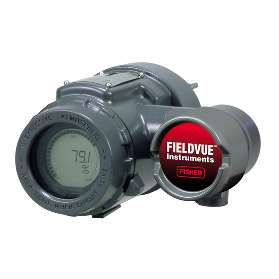
4‐20 mA analog electrical signal. The resulting current output signal is sent to an indicating or final control element. Figure 1‐1. FIELDVUE DLC3010 Digital Level Controller W7977-1 DLC3010 digital level controllers are communicating, microprocessor‐based level, interface, or density sensing instruments. -
Page 5: Related Documents
D Fisher 249VS Cageless Displacer Sensor Instruction Manual (D103288X012) D Fisher 249W Cageless Wafer Style Level Sensor Instruction Manual (D102803X012) D Simulation of Process Conditions for Calibration of Fisher Level Controllers and Transmitters (D103066X012) D Bolt Torque Information (D103220X012) D Technical Monograph 7: The Dynamics of Level and Pressure Control D Technical Monograph 18: Level‐Trol Density Transmitter... - Page 6 Introduction and Specifications Instruction Manual October 2014 D102748X012 Table 1‐1. DLC3010 Digital Level Controller Specifications Available Configurations Performance w/ NPS 3 DLC3010 Digital Level Controller: DLC3010 Performance 249W, Using w/ All Other Mounts on caged and cageless 249 sensors. See Digital Level a 14‐inch Criteria...
- Page 7 Instruction Manual Introduction and Specifications D102748X012 October 2014 Table 1‐1. DLC3010 Digital Level Controller Specifications (continued) Electromagnetic Compatibility LCD Meter Indications LCD meter indicates analog output on a percent scale Meets EN 61326‐1 and EN 61326‐2‐3 bar graph. The meter also can be configured to Immunity—Industrial locations per Table 2 of display: EN 61326‐1 and Table AA.2 of EN 61326‐2‐3.
-
Page 8: Firmware Revision
Introduction and Specifications Instruction Manual October 2014 D102748X012 Table 1‐1. DLC3010 Digital Level Controller Specifications (continued) Minimum Differential Specific Gravity (continued) encapsulated printed wiring boards; Neodymium Iron Boron Magnets See 249 sensor specifications for standard displacer volumes and standard wall torque tubes. Standard Electrical Connections volume for 249C and 249CP sensors is ∼980 cm Two 1/2‐14 NPT internal conduit connections;... - Page 9 Instruction Manual Introduction and Specifications D102748X012 October 2014 Figure 1‐2. Theoretical Reversible Temperature Effect on Common Torque Tube Materials TORQUE RATE REDUCTION (NORMALIZED MODULUS OF RIGIDITY) 1.00 0.98 0.96 0.94 0.92 N05500 N06600 0.90 N10276 0.88 0.86 0.84 0.82 S31600 0.80 20 40 80 100 120 140 160 180 200 220 240 260 280 300 320 340 360 380 400 420...
- Page 10 Introduction and Specifications Instruction Manual October 2014 D102748X012 Table 1‐3. 249 Sensor Specifications Input Signal equalizing connection styles are numbered and are shown in figure 1‐3. Liquid Level or Liquid‐to‐Liquid Interface Level:From 0 to 100 percent of displacer length Mounting Positions Liquid Density: From 0 to 100 percent of displacement force change obtained with given Most level sensors with cage displacers have a...
- Page 11 Instruction Manual Introduction and Specifications D102748X012 October 2014 Table 1‐6. Caged Displacer Sensors STANDARD CAGE, HEAD, EQUALIZING CONNECTION TORQUE TUBE SENSOR PRESSURE RATING AND TORQUE TUBE ARM ORIENTATION Style Size (NPS) MATERIAL Screwed 1‐1/2 or 2 Cast iron CL125 or CL250 Flanged Screwed or optional socket weld 1‐1/2 or 2...
- Page 12 Introduction and Specifications Instruction Manual October 2014 D102748X012 Figure 1‐3. Style Number of Equalizing Connections STYLE 3 STYLE 1 UPPER AND LOWER SIDE CONNECTIONS, TOP AND BOTTOM CONNECTIONS, SCREWED (S‐3) OR FLANGED (F‐3) SCREWED (S‐1) OR FLANGED (F‐1) STYLE 2 STYLE 4 TOP AND LOWER SIDE CONNECTIONS, UPPER SIDE AND BOTTOM CONNECTIONS,...
-
Page 13: Section 2 Installation
Instruction Manual Installation D102748X012 October 2014 Section 2 Installation2-2- This section contains digital level controller installation information including an installation flowchart (figure 2‐1), mounting and electrical installation information, and a discussion of failure mode jumpers. Configuration: On the Bench or in the Loop Configure the digital level controller before or after installation. - Page 14 Instruction Manual Installation October 2014 D102748X012 Figure 2‐1. Installation Flowchart START HERE Check Alarm Jumper Position Wire Factory mounted Digital Level on 249 sensor? Controller Power Digital Level Controller High Install heat temperature insulator application? assembly Enter Tag, Messages, Date, and check or set Mount and Wire target application data Digital level...
-
Page 15: Mounting
Hazardous Area Classifications and Special Instructions for “Safe Use” and Installations in Hazardous Locations. If a copy of this quick start guide is needed contact your Emerson Process Management sales office or visit our website at www.Fisher.com. Mounting the 249 Sensor The 249 sensor is mounted using one of two methods, depending on the specific type of sensor. -
Page 16: Digital Level Controller Orientation
Instruction Manual Installation October 2014 D102748X012 Figure 2‐2. Typical Caged Sensor Mounting Figure 2‐3. Typical Cageless Sensor Mounting A3788‐1 A3789‐1 Digital Level Controller Orientation Mount the digital level controller with the torque tube shaft clamp access hole (see figure 2‐4) pointing downward to allow accumulated moisture drainage. - Page 17 1 through 8 in figure 2‐5. To rotate the head, remove the head flange bolts and nuts and position the head as desired. Figure 2‐5. Typical Mounting Positions for the FIELDVUE DLC3010 Digital Level Controller on Fisher 249 Sensor SENSOR LEFT‐OF‐DISPLACER...
-
Page 18: Mounting The Digital Level Controller On A 249 Sensor
Instruction Manual Installation October 2014 D102748X012 Mounting the Digital Level Controller on a 249 Sensor Refer to figure 2‐4 unless otherwise indicated. 1. If the set‐screw in the access handle (figure 2‐6) is driven against the spring plate, back it out until the head is flush with the outer surface of the handle, using a 2 mm hex key. - Page 19 Instruction Manual Installation D102748X012 October 2014 Figure 2‐7. Guidelines for Use of Optional Heat Insulator Assembly AMBIENT TEMPERATURE (_C) HEAT INSULATOR REQUIRED NO HEAT INSULATOR NECESSARY -100 HEAT INSULATOR -200 COLD REQUIRED -325 100 120 AMBIENT TEMPERATURE (_F) STANDARD TRANSMITTER NOTES: 1 FOR PROCESS TEMPERATURES BELOW -29_C (-20_F) AND ABOVE 204_C (400_F) SENSOR MATERIALS MUST BE APPROPRIATE FOR THE PROCESS;...
-
Page 20: Electrical Connections
Instruction Manual Installation October 2014 D102748X012 Electrical Connections WARNING Select wiring and/or cable glands that are rated for the environment of use (such as hazardous area, ingress protection and temperature). Failure to use properly rated wiring and/or cable glands can result in personal injury or property damage from fire or explosion. -
Page 21: Field Wiring
Instruction Manual Installation D102748X012 October 2014 determine the required lift‐off voltage. If you know your total loop resistance you can determine the lift‐off voltage. If you know the available supply voltage, you can determine the maximum allowable loop resistance. Figure 2‐10. Power Supply Requirements and Load Resistance Maximum Load = 43.5 X (Available Supply Voltage - 12.0) Operating Region... -
Page 22: Grounding
Instruction Manual Installation October 2014 D102748X012 Figure 2‐11. Digital Level Controller Terminal Box 4‐20 mA LOOP TEST CONNECTIONS 1/2 NPT CONNECTIONS CONDUIT CONNECTION CONNECTIONS EXTERNAL INTERNAL GROUND GROUND CONNECTION CONNECTION 1/2 NPT CONDUIT FRONT VIEW REAR VIEW CONNECTION W8041 CAUTION Do not apply loop power across the T and + terminals. -
Page 23: Power/Current Loop Connections
Instruction Manual Installation D102748X012 October 2014 Power/Current Loop Connections Use ordinary copper wire of sufficient size to ensure that the voltage across the digital level controller terminals does not go below 12.0 volts DC. Connect the current signal leads as shown in figure 2‐9. After making connections, recheck the polarity and correctness of connections, then turn the power on. -
Page 24: Multichannel Installations
Instruction Manual Installation October 2014 D102748X012 Test connections inside the terminal box can be used to measure loop current across an internal 1 ohm resistor. 1. Remove the terminal box cap. 2. Adjust the test meter to measure a range of 0.001 to 0.1 volts. 3. -
Page 25: Alarm Jumper
Instruction Manual Installation D102748X012 October 2014 Alarm Jumper Each digital level controller continuously monitors its own performance during normal operation. This automatic diagnostic routine is a timed series of checks repeated continuously. If diagnostics detect a failure in the electronics, the instrument drives its output to either below 3.70 mA or above 22.5 mA, depending on the position (HI/LO) of the alarm jumper. -
Page 26: Loop Test
Instruction Manual Installation October 2014 D102748X012 Loop Test Field Communicator Service Tools > Maintenance > Tests > Loop Test (3-3-1-1) or (3-3-1-2) if LCD Configuration is installed Loop test can be used to verify the controller output, the integrity of the loop, and the operations of any recorders or similar devices installed in the loop. -
Page 27: Installation In Conjunction With A Rosemount 333 Hart Tri-Loopt Hart-To-Analog Signal Converter
Instruction Manual Installation D102748X012 October 2014 Installation in Conjunction with a Rosemount 333 HART Tri‐Loop HART‐to‐Analog Signal Converter Use the DLC3010 digital level controller in operation with a Rosemount 333 HART Tri-Loop HART‐to‐Analog Signal Converter to acquire an independent 4‐20 mA analog output signal for the process variable, % range, electronics temperature, and process temperature. - Page 28 The DLC3010 status words are available in the HART Burst messages. However, the Tri‐Loop cannot be configured to monitor them directly. To commission a DLC3010 digital level controller for use with a HART Tri‐Loop, perform the following procedure. Table 2‐1. Burst Variables Sent by the FIELDVUE DLC3010 Burst Option Variable...
-
Page 29: Section 3 Overview
Instruction Manual Overview D102748X012 October 2014 Section 3 Overview 3-3- Overview Field Communicator Overview (1) Device Status Good there are no active alerts and instrument is In Service Failed a failed alert is active Maintenance a configured maintenance alert is active and a failed alert is turned on Advisory a configured advisory alert is active and configured failed or a maintenance alert is turned on Comm Status Polled communication with Digital Level Controller is established. - Page 30 D Field Device Revision— the revision of the protocol for interfacing to the functionality of the instrument. D Firmware Revision— the revision number of the Fisher software in the instrument. D Hardware Revision— the revision number of the Fisher instrument hardware.
- Page 31 Instruction Manual Overview D102748X012 October 2014 Alarm Type and Security Alarm Type D Alarm Jumper— displays the position of the hardware alarm jumper, either high current or low current. D Display Alert/Saturation Level Security D Write Lock D Write Lock Setup To setup and calibrate the instrument, write lock must be set to Writes Enabled. (Write Lock is reset by a power cycle. If you have just powered up the instrument Writes will be enabled by default.) In AMS, go to Device Information in the Overview page.
- Page 32 Overview Instruction Manual October 2014 D102748X012...
-
Page 33: Section 4 Setup And Calibration
Instruction Manual Configuration D102748X012 October 2014 Section 4 Configuration and Calibration 4-4- Initial Setup If a DLC3010 digital level controller ships from the factory mounted on a 249 sensor, initial setup and calibration is not necessary. The factory enters the sensor data, couples the instrument to the sensor, and calibrates the instrument and sensor combination. -
Page 34: Configuration Advice
Guided Setup directs you through initialization of configuration data needed for proper operation. When the instrument comes out of the box, the default dimensions are set for the most common Fisher 249 construction, so if any data is unknown, it is generally safe to accept the defaults. The mounting sense 'instrument left or right of displacer' - is important for correct interpretation of positive motion. - Page 35 Instruction Manual Configuration D102748X012 October 2014 Figure 4‐1. Example Sensor Nameplate SENSOR TYPE ASSEMBLY DISPLACER DISPLACER PRESSURE RATING WEIGHT PRESSURE RATING 76543210 249B 285/100 F ASSEMBLY MATERIAL 2 x 32 INCHES WCB STL 1500 PSI 4 3/4 LBS 103 CU‐IN MONEL 316 SST K MONEL/STD...
- Page 36 Configuration Instruction Manual October 2014 D102748X012 4. Select the measurement application (level, interface, or density). Note For interface applications, if the 249 is not installed on a vessel, or if the cage can be isolated, calibrate the instrument with weights, water, or other standard test fluid, in level mode. After calibrating in level mode, the instrument can be switched to interface mode.
- Page 37 Instruction Manual Configuration D102748X012 October 2014 PV alert thresholds are initialized at 100%, 95%, 5% and 0% span. PV alert deadband is initialized to 0.5% span. PV alerts are all disabled. Temperature alerts are enabled. D If Density mode was chosen, setup is complete. D If Interface or Density mode was chosen, you are prompted to enter the specific gravity of the process fluid (if interface mode, the specific gravities of the upper and lower process fluids).
-
Page 38: Coupling
Configuration Instruction Manual October 2014 D102748X012 Coupling If the digital level controller is not already coupled to the sensor, perform the following procedure to couple the digital level controller to the sensor. 1. Slide the access handle to the locked position to expose the access hole. Press on the back of the handle as shown in figure 2‐4 then slide the handle toward the front of the unit. -
Page 39: Manual Setup
Instruction Manual Configuration D102748X012 October 2014 Manual Setup The DLC3010 digital level controller has the capability to communicate via the HART protocol. This section describes the advanced features that can be accessed with the Field Communicator. Note Changing setup parameters may require enabling writing to the instrument with the Field Communicator (Overview > Device Information >... - Page 40 Configuration Instruction Manual October 2014 D102748X012 D Driver Rod Length— Enter the displacer rod length. The displacer rod length depends upon the sensor type. For a 249 sensor, obtain the displacer rod length from table 4‐1 or from the Field Communicator Help. Refer to figure 4‐2 to physically measure this value.
-
Page 41: Variables
Instruction Manual Configuration D102748X012 October 2014 Variables Field Communicator Configure > Manual Setup > Variables (2-2-2) Primary Variables Follow the prompts on the Field Communicator to view or edit Primary Variable information. D PV is— Display the PV currently stored in the instrument. Change PV—... - Page 42 Configuration Instruction Manual October 2014 D102748X012 Sensor Limits Follow the prompts on the Field Communicator to view sensor limit information. D Upper Sensor Limit— Indicates the maximum usable value for the Upper Range Value. D Lower Sensor Limit— Indicates the minimum usable value for the Lower Range Value. D Minimum Span—...
-
Page 43: Process Fluid
Instruction Manual Configuration D102748X012 October 2014 PV Damping PV Damping changes the response time of the controller to smooth variations in output readings caused by rapid changes in input. Determine the appropriate damping setting based on the necessary response time, signal stability, and other requirements of the loop dynamics of your system. - Page 44 Configuration Instruction Manual October 2014 D102748X012 Table 4‐2. Example Specific Gravity vs Temperature Table for Saturated Water Temperature Data Point Specific Gravity 26.7 80.0 0.9985 93.3 200.0 0.9655 176.7 350.0 0.8935 248.9 480.0 0.8040 304.4 580.0 0.7057 337.8 640.0 0.6197 354.4 670.0 0.5570...
- Page 45 Instruction Manual Configuration D102748X012 October 2014 gravity value, select Single Point and enter the specific gravity value. To display or enter values in the tables, select Table of SG vs T. The Field Communicator begins by prompting for the temperature of the first pair in the lower table. After entering the temperature for the first pair, press ENTER.
-
Page 46: Device Information
Configuration Instruction Manual October 2014 D102748X012 Figure 4‐5. Example Saturated Steam Curve Plotted from Values in Table 4‐3 TEMPERATURE _C 0.35 0.30 0.25 0.20 0.15 0.10 0.05 TEMPERATURE _F E0370 Process Temperature The digital level controller can receive the process temperature from a resistance temperature detector (RTD) connected to the unit or, if no RTD is connected to the unit, you can enter the process temperature directly. -
Page 47: Instrument Display
Instruction Manual Configuration D102748X012 October 2014 D Date— Date is a user‐defined variable that provides a place to save the date of the last revision of configuration or calibration information. It has no impact on the operation of the controller or Field Communicator. Enter a date with the format MM/DD/YY. - Page 48 Configuration Instruction Manual October 2014 D102748X012 If PV/Proc Temp or PV/% Range is selected, the display alternates every two seconds between the selected readings. The meter also simultaneously displays the analog output signal using a percent of scale bar graph around the perimeter of the display face as shown in figure 4‐6, no matter what display type is selected.
-
Page 49: Alert Setup
Instruction Manual Configuration D102748X012 October 2014 Alert Setup The following menus are available for configuring Alerts. Primary Variable Field Communicator Configure > Alert Setup > Primary Variable (2-3-1) Follow the prompts on the Field Communicator display to view or edit the following primary variable alerts. Primary Variable Hi D Hi Alert PV Hi Alert Enable—... - Page 50 Configuration Instruction Manual October 2014 D102748X012 PV Lo Alert Threshold— Primary Variable Lo Alert Threshold is the value of the primary variable, in engineering units, which, when exceeded, sets the Primary Variable Low Alert. PV Lo Alert Threshold— Method to change the PV Lo Alert Threshold D Lo Lo Alert PV LoLo Alert Enable—...
-
Page 51: Temperature
Instruction Manual Configuration D102748X012 October 2014 Temperature Field Communicator Configure > Alert Setup > Temperature (2-3-2) Follow the prompts on the Field Communicator display to set the following temperature alerts. Instrument Temperature D Hi Alert Inst Temp Hi Alert Enable— On or Off. Instrument Temperature High Alert Enable activates checking of the instrument temperature against the Instrument Temperature High Alert Threshold. -
Page 52: October 2014
Configuration Instruction Manual October 2014 D102748X012 Proc Temp Lo Alert Threshold— Process Temperature Low Alert Threshold is the process variable temperature, in temperature units, which, when exceeded, will set the Temperature Low Alert. D Proc Temp— Displays the process temperature stored in the instrument. D Proc Temp Offset—... -
Page 53: Communications
Depending upon the burst option selected, the digital level controller will burst the variables as shown in table 2‐1. Table 4‐4. Burst Variables Sent by the FIELDVUE DLC3010 Burst Option... -
Page 54: Calibration
Configuration Instruction Manual October 2014 D102748X012 Calibration Introduction: Calibration of Smart Instruments Analog instruments generally have only one interface that can be calibrated by the user. A zero and span output calibration is normally performed at the corresponding two input conditions. Zero/Span calibration is very simple to use, but provides little versatility. -
Page 55: Full Calibration
Instruction Manual Configuration D102748X012 October 2014 Full Calibration Field Communicator Configure > Calibration > Primary > Full Calibration (2-5-1-2) Full Calibration operations compute the sensor gain and offset from two independent observations of process data points. They are appropriate for cases where the two input conditions can be established relatively quickly in one session. -
Page 56: Weight Calibration
Note The theoretical torque rate for the installed torque tube is available in the Simulation of Process Conditions for Calibration of Fisher Level Controllers and Transmitters instruction manual supplement (D103066X012). Contact your Emerson Process Management sales office for information on obtaining this manual supplement. -
Page 57: Partial Calibration
Instruction Manual Configuration D102748X012 October 2014 Observations of the sight glass or other independent measurements may be logged against DLC3010 outputs over time. The ratio of the independent‐observable process changes to the DLC3010 output changes may then be used as a scale factor to modify the theoretical torque rate stored in the instrument. -
Page 58: Trim Zero
Configuration Instruction Manual October 2014 D102748X012 and able to be measured independently. Configuration data must contain density of calibration fluid, displacer volume, and driver rod length. Before calibration, use the Configure > Manual Setup >Sensor menu to verify that all sensor and compensation data match the calibration conditions. -
Page 59: Trim Instrument Temperature
Instruction Manual Configuration D102748X012 October 2014 Trim Instrument Temperature Follow the prompts on the Field Communicator to trim the instrument temperature. Trim Process Temperature Trim Process Temperature is available if the Process Temperature Source is not Manual. Follow the prompts on the Field Communicator to trim the process temperature. -
Page 60: Calibration Examples
Configuration Instruction Manual October 2014 D102748X012 8. If the reference meter reading equals 4 mA or the low output value, select Yes and continue to step 9. If not, select No and return to step 7. 9. The Field Communicator commands the instrument to set its output to 20 mA or the high output value. 10. -
Page 61: Calibration With Overweight Displacer
Note Information on computing precise simulation of this effect is available in the Simulation of Process Conditions for Calibration of Fisher Level Controllers and Transmitters instruction manual supplement (D103066X012), available from your Emerson Process Management sales office or at www.fisher.com. - Page 62 The last step above will align the value of the PV in engineering units to the sight glass observation. Note Information on simulating process conditions is available in the Simulation of Process Conditions for Calibration of Fisher Level Controllers and Transmitters instruction manual supplement (D103066X012), available from your Emerson Process Management sales office or at www.fisher.com.
-
Page 63: Density Applications - With Standard Displacer And Torque Tube
Instruction Manual Configuration D102748X012 October 2014 Density Applications - with Standard Displacer and Torque Tube Note When you change 'PV is' from level or interface to density, the range values will be initialized to 0.1 and 1.0 SGU. You may edit the range values according to the specify gravity unit. -
Page 64: Entering Theoretical Torque Tube Rates
Entering Theoretical Torque Tube (TT) Rates The Simulation of Process Conditions for Calibration of Fisher Level Controllers and Transmitters instruction manual supplement (D103066X012) provides the theoretical composite torque tube (TT) rate for 249 sensors with DLC3010 controllers. -
Page 65: Excessive Mechanical Gain
Instruction Manual Configuration D102748X012 October 2014 These steps will provide an approximate PV calibration to get a system operational. Further refinements can then be made when it is possible to manipulate and observe the level and instrument output. Excessive Mechanical Gain If the displacer/torque tube sizing provides more than 4.4 degrees of torque tube rotation for a full span change in process input, It may be difficult to obtain a valid calibration with the normal coupling procedure. -
Page 66: Extreme Temperatures
Note For additional information, refer to the Simulation of Process Conditions for Calibration of Fisher Level Controllers and Transmitters instruction manual supplement (D103066X012), available from your Emerson Process Management sales office or at www.fisher.com. -
Page 67: Section 5 Service Tools
Instruction Manual Service Tools D102748X012 October 2014 Section 5 Service Tools 5-5- Active Alerts Field Communicator Service Tools > Active Alerts (3-1) Visible if an alert is not active No Active Alerts Visible if an alert is active Refresh Alerts—the following menu/methods will be visible only if the associated alert is active: D F: Process Temperature Signal Failed - When active, indicates the process temperature sensor (RTD) reading has exceeded the hardcoded limits (<10 ohms or >320 ohms). -
Page 68: Variables
Service Tools Instruction Manual October 2014 D102748X012 D A: PV HiHi Alert - When active, indicates that the Process Variable has exceeded the value of the Process Variable High High Alert Threshold. Analog Output set to jumperselected alarm current. D A: PV Hi Alert - When active, indicates that the Process Variable has exceeded the value of the Process Variable High Alert Threshold. - Page 69 Instruction Manual Service Tools D102748X012 October 2014 Figure 5‐1. PV % Range Indication for Direct and Reverse Action with a 32‐Inch Displacer Ranged for 8 to 24 Inches –10 –10 –30 –30 –50 –50 LEVEL (INCHES) LEVEL (INCHES) DIRECT ACTION REVERSE ACTION E0383 AO—...
-
Page 70: Maintenance
Service Tools Instruction Manual October 2014 D102748X012 Maintenance Tests Field Communicator Service Tools > Maintenance > Tests (3-3-1-1) LCD Test— only visible if LCD Configuration is installed The meter activates all segments immediately after power‐up, during a digital level controller self‐test, or during a master reset sent by a host supporting HART communications. -
Page 71: Section 6 Maintenance And Troubleshooting
Instruction Manual Maintenance & Troubleshooting D102748X012 October 2014 Section 6 Maintenance & Troubleshooting 6‐6‐ The DLC3010 digital level controller features a modular design for easy maintenance. If you suspect a malfunction, check for an external cause before performing the diagnostics described in this section. Sensor parts are subject to normal wear and must be inspected and replaced as necessary. -
Page 72: Hardware Diagnostics
Maintenance & Troubleshooting Instruction Manual October 2014 D102748X012 Figure 6‐1. LCD Meter Diagnostic Display ANALOG DISPLAY OF OUTPUT PROCESS VARIABLE VALUE DIAGNOSTIC MESSAGE MODE E0380 D FAIL HDWR— This message indicates the existence of one or more of the following conditions: —The primary sensor input conversion is out of range. - Page 73 Instruction Manual Maintenance & Troubleshooting D102748X012 October 2014 Table 6‐1. Troubleshooting Symptom Potential Source Corrective Action 1. Check resistance between the power supply and the Field Communicator connection. The net resistance in the loop must be between 230 and 1100 Ohms for HART communication. 2.
-
Page 74: Test Terminals
Maintenance & Troubleshooting Instruction Manual October 2014 D102748X012 Test Terminals Test connections inside the terminal box can be used to measure loop current. These terminals are across an internal 1 ohm resistor that is in series with the loop. 1. Remove the terminal box cap. 2. -
Page 75: Removing The Dlc3010 Digital Level Controller From A 249 Sensor
Instruction Manual Maintenance & Troubleshooting D102748X012 October 2014 Table 6‐2. Tools Required Tool Size Usage Keys Handle Hex Key 2 mm Cover‐lock set screws Hex Key 2.5 mm Small cap screws Hex Key 4 mm Lever assembly mtg cap screw Hex Key 5 mm Terminal box mtg cap screw... -
Page 76: High Temperature Applications
Maintenance & Troubleshooting Instruction Manual October 2014 D102748X012 7. When re‐installing the digital level controller, follow the appropriate procedure outlined in the Installation section. Also setup the digital level controller as described in the Initial Setup section. 249 Sensor in High Temperature Applications 1. -
Page 77: Removing The Lcd Meter Assembly
Instruction Manual Maintenance & Troubleshooting D102748X012 October 2014 The digital level controller is designed with a dual‐compartment housing; one compartment contains the LCD meter and Electronics Module; the other contains all wiring terminals and the communication receptacles. The LCD meter is located in the compartment opposite the wiring terminals, as shown in figure 6‐2. -
Page 78: Electronics Module
Maintenance & Troubleshooting Instruction Manual October 2014 D102748X012 the long meter screws into the two holes on the meter to coincide with the appropriate holes on the Electronics Module. 3. Attach the meter to the interconnection pins. Thread the long meter screws into the holes on the Electronics Module and tighten to secure the meter. -
Page 79: Terminal Box
Instruction Manual Maintenance & Troubleshooting D102748X012 October 2014 1. Carefully insert the Electronics Module to mate the interconnecting pins with the receptacles on the Transducer housing. CAUTION To prevent damage to the interconnecting pins when installing the Electronics Module, use the guide pins to insert the Electronics Module straight onto the Transducer housing receptacles without twisting or turning. -
Page 80: Removing And Replacing The Inner Guide And Access Handle Assembly
Maintenance & Troubleshooting Instruction Manual October 2014 D102748X012 1. Apply sealant to the O‐ring (key 27) and install the O‐ring over the stem of the terminal box as shown in figure 7‐3. 2. Orient the terminal box so that the connectors engage properly, and carefully insert the terminal box into the transducer housing until the O‐ring is seated. -
Page 81: Lever Assembly
Instruction Manual Maintenance & Troubleshooting D102748X012 October 2014 Figure 6‐3. Installing Inner Guide and Access Handle Assembly SCREWS (KEY 13) HANDLE ASSEMBLY (KEY 12) VENT HOLES LUBRICATE LUBRICATE THIS SURFACE THIS SURFACE VENT HOLE TRANSDUCER HOUSING INNER GUIDE ZERO LOCKING PIN (KEY 11) ACCESS HOLE E0381... -
Page 82: Replacing The Lever Assembly
Maintenance & Troubleshooting Instruction Manual October 2014 D102748X012 1. Remove the digital level controller from the sensor as described in Removing the Digital Level Controller from the Sensor. 2. Loosen and remove the hex nuts (key 34) from the studs (key 33) and remove the adapter ring (key 32). 3. -
Page 83: Packing For Shipment
Instruction Manual Maintenance & Troubleshooting D102748X012 October 2014 Packing for Shipment If it becomes necessary to return the unit for repair or diagnosis, contact your Emerson Process Management sales office for returned goods information. CAUTION Lock the lever assembly when shipping the stand‐alone instrument, to prevent damage to the flexure. Use the original shipping carton if possible. - Page 84 Maintenance & Troubleshooting Instruction Manual October 2014 D102748X012...
-
Page 85: Section 7 Parts
Use only genuine Fisher replacement parts. Components that are not supplied by Emerson Process Management, should not, under any circumstances, be used in any Fisher instrument. The use of components not manufactured by Emerson Process Management may void your warranty, might adversely affect the performance of the instrument, and could cause personal injury and property damage. -
Page 86: Parts List
Parts Instruction Manual October 2014 D102748X012 Parts List Description Part Number Cover Assy, includes O‐ring (key 21) LCD Meter Ass'y, includes alarm jumper (key 35), Description Part Number header ass'y (key 38) and captive screws (key 40), and LCD Meter ass'y 28B5738X012 Terminal Box Ass'y 28B5740X022... -
Page 87: Transducer Assembly
Instruction Manual Parts D102748X012 October 2014 Description Part Number Description Machine Screw, pan head Set Screw, 18‐8 SST Set Screw, hex socket, 18‐8 SST Thread Locking adhesive (medium strength) Transducer Assembly (figure 7‐2) (not furnished with instrument) Inner Guide, aluminum Sealant (2)(6) Handle Ass'y aluminum/SST... -
Page 88: Terminal Box Assembly
Parts Instruction Manual October 2014 D102748X012 Figure 7‐3. Terminal Box Assembly SECTION A‐A APPLY LUBRICANT 28B5740-B Description Part Number Figure 7‐4. Terminal Box Cover Assembly Terminal Box Assembly (figure 7‐3) Test Terminal, 18‐8 SST (2 req'd) Wire Retainer, 18‐8 SST (8 req'd) O‐Ring, nitrile 1H8762X0012 O‐Ring, nitrile... -
Page 89: Mounting Parts
Instruction Manual Parts D102748X012 October 2014 Figure 7‐5. Mounting Kit for 249 Sensors with Heat Insulator 28B5741‐A Mounting Parts Description Masoneilan Sensors (figures 7‐6 and 7‐7) These parts are available as a kit as indicated in the 12100 or 12800 without Heat Insulator Mounting Kits section. - Page 90 Parts Instruction Manual October 2014 D102748X012 Figure 7‐6. Mounting Kit for Masoneilan 12200 and 12300 Sensor without Heat Insulator 29B8444‐A Figure 7‐7. Mounting Kit for Masoneilan 12200 and 12300 Sensor with Heat Insulator 29B8445‐A Description Description 12200 or 12300 with Heat Insulator 12200 or 12300 without Heat Insulator Heat Insulator, S30400 Shaft Extension, S31600...
- Page 91 Instruction Manual Parts D102748X012 October 2014 Description Description Foxboro‐Eckardt Sensors Yamatake NQP Sensor 144LD without Heat Insulator Shaft Extension, S31600 Without Heat Insulator Shaft Coupling, S30300 Set Screw, hex socket, SST (2 req'd) Shaft Extension, S31600 Mounting Adapter, A92024 Shaft Retainer, S30400 Hex Nut, steel (4 req'd) Hex Socket Screw, SST Hex Cap Screw, steel (4 req'd)
- Page 92 Parts Instruction Manual October 2014 D102748X012...
-
Page 93: Multidrop Communication
Instruction Manual Principle of Operation D102748X012 October 2014 Appendix A Principle of OperationA‐ HART Communication The HART (Highway Addressable Remote Transducer) protocol gives field devices the capability of communicating instrument and process data digitally. This digital communication occurs over the same two‐wire loop that provides the 4-20 mA process control signal, without disrupting the process signal. -
Page 94: Digital Level Controller Operation
Principle of Operation Instruction Manual October 2014 D102748X012 Figure A‐2. Typical Multidropped Network BELL 202 MODEM LOAD HOST POWER SUPPLY E0375 The Field Communicator can test, configure, and format a multidropped DLC3010 digital level controller in the same way as in a standard point‐to‐point installation. Note DLC3010 digital level controllers are set to address 0 at the factory, allowing them to operate in the standard point‐to‐point manner with a 4-20 mA output signal. - Page 95 TERMINAL BOX COVER TRANSDUCER BOARD LEVER ASSEMBLY HOUSING ELECTRONICS ASSEMBLY LCD METER ASSEMBLY E0377 COVER Figure A‐4. FIELDVUE DLC3010 Digital Level Controller Principle of Operation Transducer Module Electronics Temperature Sensor Processor Terminal Loop / HART Shaft Position Torque Tube Module Interface...
- Page 96 Principle of Operation Instruction Manual October 2014 D102748X012 The transducer board contains the Hall sensor, a temperature sensor to monitor the Hall sensor temperature, and an EEPROM to store the coefficients associated with the Hall sensor. The terminal board contains the EMI filters, the loop connection terminals, and the connections for the optional RTD used to measure process temperature.
- Page 97 Instruction Manual Principle of Operation D102748X012 October 2014 Figure A‐6. Digital Level Controller Analog Output Signal Output Saturated (20.5 mA) Output during Alarm with Alarm Jumper in Hi Position (22.5 mA) Normal Operation Output Saturated Output during Alarm with (3.8 mA) Alarm Jumper in Lo Position (3.7 mA)
- Page 98 Principle of Operation Instruction Manual October 2014 D102748X012...
-
Page 99: Appendix B Field Communicator Menu Tree
Instruction Manual Field Communicator Menu Tree D102748X012 October 2014 Appendix B Fast-Key Sequence and Field Communicator Menu TreeB‐B‐0 Fast-key sequences are included for common DLC3010 digital level controller fuctions. Also included are Field Communiator menu trees. D Fast-key sequences, see table B‐1 D Hot Key menu, see figure B‐1 D Overview menu, see figure B‐2 D Guided Setup menu, see figure B‐3... - Page 100 Field Communicator Menu Tree Instruction Manual October 2014 D102748X012 Table B‐1. Fast Key Sequence Function Fast-Key Sequence See Figure Function Fast-Key Sequence See Figure Active Alerts B‐8 Lower Sensor Limit 2-2-2-2-2 B‐4 Alarm Jumper 1-7-3-1-1 B‐2 Measure Density 2-2-3-1-4 B‐4 B‐2 Message 2-2-4-4...
- Page 101 Instruction Manual Field Communicator Menu Tree D102748X012 October 2014 Figure B‐1. Hot Key Hot Key 1 Write Lock 2 Write Lock Setup 3 Change PV 4 Enter Contstant Density Figure B‐2. Overview 1‐4 Primary Variable 1‐1 Device Status 1 PV Value 2 % Range 1 Refresh Alerts 2 No Active Alerts 1‐6 Process Temperature...
- Page 102 Field Communicator Menu Tree Instruction Manual October 2014 D102748X012 Figure B‐4. Configure > Manual Setup Configure 2‐2‐1-1 1 Guided Setup Sensor Units 2 Manual Setup 1 Length Units 3 Alert Setup 2‐2‐1 2 Volume Units Sensor 4 Communications 3 Weight Units 5 Calibration 1 Sensor Units 4 Torque Rate Units 2 Sensor Dimensions 5 Temperature Units 3 Torque Tube...
- Page 103 Instruction Manual Field Communicator Menu Tree D102748X012 October 2014 Figure B‐5. Configure > Alert Setup Configure 2‐3-1-1-1 Hi Alert 1 Guided Setup 2 Manual Setup 1 PV Hi Alert Enable 3 Alert Setup 2 PV Hi Alert Threshold 2‐3-1 2‐3-1-1 4 Communications 3 PV Hi Alert Threshold (Method) Primary Variable Primary Variable Hi 5 Calibration...
- Page 104 Field Communicator Menu Tree Instruction Manual October 2014 D102748X012 Figure B‐7. Configure > Calibration 2‐5-1-2 Full Calibration 2‐5 Configure 1 Min/Max Calibration Calibration 2‐5-1 2 Two Point Calibration 1 Guided Setup 1 Primary Primary 3 Weight Calibration 2 Manual Setup 2 Secondary 2‐5-1-3 1 Guided Calibration 3 Alert Setup Partial Calibration 2 Full Calibration 4 Communications...
-
Page 105: Glossary
Instruction Manual Glossary D102748X012 October 2014 Glossary Alarm Deadband Control Loop The amount by which the process variable must An arrangement of physical and electronic return within normal limits for the alarm to clear. components for process control. The electronic components of the loop continuously measure one or more aspects of the process, then alter those aspects as necessary to achieve a desired... - Page 106 ENTER, or by Hardware Revision entering the numeric value of the menu item. Revision number of the Fisher instrument hardware. The physical components of the Message instrument are defined as the hardware.
- Page 107 Instruction Manual Glossary D102748X012 October 2014 Random Access Memory (RAM) Software A type of semiconductor memory that is normally Microprocessor or computer programs and used by the microprocessor during normal routines that reside in alterable memory (usually operation that permits rapid retrieval and storage RAM), as opposed to firmware, which consists of of programs and data.
- Page 108 Instruction Manual Glossary October 2014 D102748X012...
- Page 109 Instruction Manual Index D102748X012 October 2014 Index Calibration access handle, 15 Analog Output, 59 Full, 55 Access Handle Assembly, removing and replacing, 80 Guided, 54 Min/Max, 55 Active Alerts, Service Tools, 67 Partial, 57 Advisory, Device Status, 29 Capture Zero, 57 Trim Gain, 57 Alarm Jumper, 25, 31 Trim Zero, 58...
- Page 110 Instruction Manual Index October 2014 D102748X012 configuration data, factory, 33 Displacer Sensors Caged, 11 Connection Styles, Caged Sensor, 10 Cageless, 11 Connections displacer serial number, 47 Communication, 23 Displacer Volume, 54 current loop, 20 Electrical, 20 Display Alert/Saturation Level, 31 Power/Current Loop, 23 Display Mode, 47 RTD, 23...
- Page 111 Instruction Manual Index D102748X012 October 2014 Field Wiring, 21 Final Assembly Number, 47 Immunity Performance, 8 Firmware Revision, 30 Independent Linearity, 6 Flexures, protecting, 13 Initial Setup, 33 FSETAN, 7 INMETRO, 7 Full Calibration, 55 Inner Guide and Access Handle Assembly, Removing and Replacing, 80 Input Signal Good, Device Status, 29...
- Page 112 Instruction Manual Index October 2014 D102748X012 Maintenance LCD Configuration, Instrument Display, 47 Device Status, 29 removing the DLC3010 from a 249 sensor LCD meter, 17, 94 high temperature application, 76 Assembly, 76 standard temperature application, 75 Diagnostic Messages, 71 Reset/Restore, 70 [BLANK], 71 Service Tools, 70 FAIL HDWR, 72...
- Page 113 Instruction Manual Index D102748X012 October 2014 multidrop communication Primary Variable, 29 activating, 94 Alert Setup, 49 Service Tools, Variables, 68 Principle of Operation, 93 Primary Variable Hi, Alert Setup, 49 Multidrop installations, intrinsic safety, 93 Primary Variable Lo, Alert Setup, 49 Multidropped Communication, Typical Multidropped Network, 93 Primary Variable Range, 42...
- Page 114 Instruction Manual Index October 2014 D102748X012 PV HiHi Alert Threshold, 49 Security, 31 method, 49 Sensor Connection Compartment, 16 PV is, 29, 41 Sensor Damping, 40 Service Tools, Variables, 68 Sensor Dimensions, 39 PV Lo Alert Enable, 49 Sensor Limits, 42 PV Lo Alert Threshold, 50 Sensor Nameplate, example, 35 method, 50...
- Page 115 Instruction Manual Index D102748X012 October 2014 Test connections, 24 Test Terminals, 23, 74 Upper Density Table, 43 Tests, Maintenance, 70 Upper Fluid Density Theoretical Reversible Temperature Effect on process fluid, 43 Common Torque Tube Materials, 9 Service Tools, Variables, 69 Theoretical Torque Tube (TT) Rates, 64 Upper Range Value, primary variable, 42, 50 TIIS, 7...
-
Page 116: Www.fisher.com
Responsibility for proper selection, use, and maintenance of any product remains solely with the purchaser and end user. Fisher, FIELDVUE, DeltaV, and Tri‐Loop are marks owned by one of the companies in the Emerson Process Management business unit of Emerson Electric Co.