Sign In
Upload
Manuals
Brands
WAGO Manuals
Control Unit
761-114
WAGO 761-114 Manuals
Manuals and User Guides for WAGO 761-114. We have
1
WAGO 761-114 manual available for free PDF download: Manual
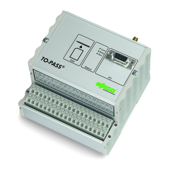
WAGO 761-114 Manual (126 pages)
Telecontrol Module Compact, 2 AI, Web, MODBUS485 for WAGO-TO-PASS 761, Telecontrol module for fault detection/indication, monitoring and remote control
Brand:
WAGO
| Category:
Control Unit
| Size: 3 MB
Table of Contents
Table of Contents
3
Table of Contents
5
Notes about this Documentation
7
Validity of this Documentation
7
Copyright
7
Symbols
8
Number Notation
10
Font Conventions
10
Table 1: Number Notation
10
Table 2: Font Conventions
10
Important Notes
11
Legal Bases
11
Subject to Changes
11
Personnel Qualification
11
Use of the TO-PASS Telecontrol Modules in Compliance with Underlying Provisions
11
Technical Condition of Specified Devices
11
Disclaimer
12
Firmware Licensing Terms
12
Firmware with Open Source GPL
12
Block Rounding for GPRS Connections
12
Safety Advice (Precautions)
13
Device Description
16
Scope of Delivery
16
Use
16
Table 3: Overview of Functions
17
View
18
Figure 1: Front View
18
Connectors
19
Antenna
19
Figure 2: Antenna Connection
19
Operating Voltage
20
Figure 3: Terminal Assignment for Operating Voltage
20
Table 4: Terminal Assignment for Operating Voltage
20
Grounding
21
Framework Assembly
21
Insulated Assembly
21
Grounding of the TO-PASS
21
Telecontrol Module
21
Table 5: WAGO Ground Wire Terminals
21
Shielding
22
General
22
Bus Lines
22
Signal Lines
22
WAGO Shield Connecting System
23
Figure 4: Example of the WAGO Shield Connecting System
23
Digital Inputs
24
Figure 5: Terminal Assignment for Digital Inputs
24
Table 6: Terminal Assignment for Digital Inputs
24
Counter Inputs
25
Figure 6: Counter Input Pin Assignments
25
Table 7: Counter Input Pin Assignments
25
Analog Inputs
26
Figure 7: Terminal Assignment for Analog Inputs
26
Table 8: Terminal Assignment for Analog Inputs
26
Digital Outputs
28
Figure 8: Terminal Assignment for Digital Outputs
28
Table 9: Terminal Assignment for Digital Outputs
28
Serial Interface to the PC and MODBUS Interface
29
Figure 9: Serial Interface to the PC and MODBUS Interface
29
Table 10: Serial Interface to the PC and MODBUS Interface
29
Table 11: PC Interface Cable Assignment
29
Figure 10: MODBUS Communication Diagram
30
Table 12: MODBUS Cable Assignment
30
Display Elements
32
Figure 11: Display Elements
32
Table 13: Display Elements
32
Technical Data
33
Housing
33
Supply
33
GSM Antenna Connection
33
Table 14: Technical Data Housing
33
Table 15: Technical Data Supply
33
Table 16: Technical Data GSM Antenna Connection
33
GSM Communication
34
MODBUS Communication
34
Digital Inputs
34
Counter Inputs
34
Table 17: Technical Data Communication
34
Table 18: Technical Data MODBUS Communication
34
Table 19: Technical Data Digital Inputs
34
Table 20: Technical Data Counter Inputs
34
Analog Inputs
35
Digital Outputs
35
Table 21: Technical Data Analog Inputs
35
Table 22: Technical Data Digital Outputs
35
Approvals
36
Standards and Guidelines
36
Mounting
37
Mounting the TO-PASS ® Telecontrol Module to the DIN Rail
37
Figure 12: Mounting the TO-PASS ® Telecontrol Module to the DIN Rail
37
Removing the TO-PASS ® Telecontrol Module from the DIN Rail
38
Figure 13: Removing the TO-PASS ® Telecontrol Module from the DIN Rail
38
Connect Devices
39
Connecting the Push-Wire Connections to the Conductor
39
Connection Examples
40
Digital Inputs
40
Figure 14: Connection Example for a Switch at DI1 Input
40
Counter Inputs
41
Figure 15: Connecting Example, Switching Contact at Counter Input DI1
41
Analog Inputs
42
Current Measurement
42
Figure 16: Connection Example for a Transducer at AI1 Input
42
Voltage Measurement
43
Figure 17: Connection Example for Voltage Measurement Via U/I Converter at
43
Digital Outputs
44
Figure 18: Connection Example for a Relay at DO1 Output
44
MODBUS Interface
45
MODBUS Coupler/Controller RS-485
46
Figure 19: Connection Example for MODBUS Coupler/Controller RS-485
46
Serial Interface for MODBUS Current Sensor and PC
47
Figure 20: Connection Example for Serial Interface for MODBUS Current Sensor and PC
47
Commissioning
48
Installing the Operating Software
48
Starting the TO-PASS Telecontrol Module
49
Parameterizing
51
General Settings
51
Figure 21: General Settings
51
Table 23: General Settings
51
Reading Parameters from the Module
53
Identity
54
Figure 22: Configuring the Identity
54
Table 24: Configuring the Identity
55
Addresses
56
Figure 23: Configuring the Addresses
56
Table 25: Configuring the Addresses
57
Configuring Inputs and Outputs
59
Digital Inputs
59
Figure 24: Configuring Digital Inputs 1
59
Figure 25: Configuring Digital Inputs 5
60
Table 26: Configuring of Digital Inputs
60
Multiplex Input
63
Multiplex Settings
64
Figure 26: Configuring Multiplex Operation Settings
64
Table 27: Configuring Multiplex Operation Settings
64
Multiplex Alarm Text
65
Figure 27: Configuring Multiplex Operation Alarm Texts
65
Table 28: Configuring Multiplex Operation Alarm Texts
65
Analog Inputs
66
Figure 28: Configuring the Analog Inputs
66
Table 29: Configuring the Analog Inputs
66
Digital Outputs
68
Figure 29: Configuring the Digital Outputs
68
Table 30: Configuring the Digital Outputs
68
Configuring Error Detectors
69
Alarm Messages for Digital Inputs
69
Limit Messages for Counter Inputs
69
Limit Messages for Analog Inputs
69
Acknowledgement
71
Figure 30: : Configuring the Acknowledgment Response
71
Table 31: Configuring the Acknowledgement Response
71
Transmission Repeat Times
72
Figure 31: Configuring the Transmission Repeat Times
72
Table 32: Configuring the Transmission Repeat Times
73
Time Adjustment
75
Figure 32: Setting the Time Adjustment
75
Table 33: Setting the Time Adjustment
75
Modbus
76
MODBUS Settings
77
Figure 33: Configuring the MODBUS Settings
77
Table 34: Configuring the MODBUS Settings
77
MODBUS Alarm
78
Figure 34: Configuring the MODBUS Alarm
78
Table 35: Configuring the MODBUS Alarm
78
MODBUS Registers
79
Figure 35: Configuring the MODBUS Registers
79
Table 36: Configuring the MODBUS Registers
79
Writing Parameters to the Module
80
Operation
81
Remote Query of Process Values
81
Remote Polling Via SMS
82
Table 37: SMS Format
82
Table 38: Items Added to SMS for Counter Inputs
82
Table 39: Counter Status
83
Remote Polling Using the TO-PASS
84
Operating Program
84
Inputs/Outputs
85
Figure 36: Visualization of the Process Values
85
Modbus
86
Figure 37: MODBUS Process Values
86
Counters
87
Figure 38: Counter Process Values
87
Telecontrol
88
Telecontrol Via SMS
89
Setting or Resetting a Digital Output
89
Table 40: Example of Parameters for Set DO
89
Changing the Counter Value or Status
90
Table 41: Control Commands for Counters
90
Telecontrol with the TO-PASS
91
Operator Program
91
Inputs/Outputs
92
Figure 39: Visualization of the Process Values
92
Counters
93
Figure 40: Counter Process Values
93
Acknowledging Error Messages
94
Switching to Standby
95
Diagnostics
96
Test Inputs and Outputs
96
Figure 41: Test Inputs and Outputs
96
Testing the Counter Inputs
97
Figure 42: Testing Counters
97
Testing the Connection
98
Figure 43: Testing the Connection
98
Testing the Modem
99
Figure 44: Testing the Modem
99
WAGO TO-PASS Web
100
Setting Parameters
100
HTTP Request
101
Example HTTP Request
101
Data Sets
102
Value Script
102
Value Script FW 2.20 (Standard)
103
Table 42: Data Format for Value Script FW 2.20 (Standard)
103
Example of Value Script FW 2.20 (Standard)
104
Value Script FW 2.31 (Extended)
105
Table 43: Data Format for Value Script FW 2.31 (Extended)
105
Table 44: Meaning of Flag
106
Example of Value Script FW 2.31 (Extended)
107
Value Script FW 2.33 (Counter Inputs)
108
Table 45: Counter Status
108
Table 46: Alarm Status
109
Table 47: Signal Quality (from at Reference Guide by Telit)
109
Example of Value Script FW 2.33 (Counter Inputs)
110
Logger Script
111
Logger Script Standard
112
10.3.2.1.1 Binary Data Format for Data Set
112
Table 48: Data Format for Logger Script FW 2.20 (Standard)
112
10.3.2.1.2 Example for Logger Script Standard
113
Logger Script Extension
114
Table 49: Data Format for Logger Script FW 2.31 (Extended)
114
10.3.2.2.1 Data Format for Liox Variable
115
10.3.2.2.2 Data Format for Lpdx Variable
115
Table 50: Data Format for Logger Script FW 2.31 (Extended), Variable Liox
115
Table 51: Data Format for Logger Script FW 2.31 (Extended), Variable Lpdx
115
10.3.2.2.3 Example for Logger Script Extension
116
Logger Script FW 2.33 (Counter Inputs)
118
10.3.2.3.1 Data Format of an Lcdx Variable
118
Table 52: Data Format, Logger Script Extension, Variable Lcdx
118
Table 53: Counter Status
118
Table 54: Number of Data Sets
119
Time Request Script FW 2.33
120
HTTP Response
121
Table 55: Setpoint Settings
121
Example of HTTP Response
122
List of Figures
123
List of Tables
124
Advertisement
Advertisement
Related Products
WAGO 761-113
WAGO 761-111
WAGO 761-112
WAGO 761-110
WAGO 761-216
WAGO 761-214
WAGO 761-217
WAGO 761-314
WAGO 761-210
WAGO 761-316
WAGO Categories
I/O Systems
Control Unit
Power Supply
Switch
Controller
More WAGO Manuals
Login
Sign In
OR
Sign in with Facebook
Sign in with Google
Upload manual
Upload from disk
Upload from URL