Sign In
Upload
Manuals
Brands
Snap-On Manuals
Diagnostic Equipment
Zeus
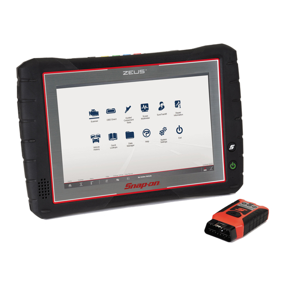
Snap-On Zeus Manuals
Manuals and User Guides for Snap-On Zeus. We have
4
Snap-On Zeus manuals available for free PDF download: User Manual, Getting Started Pack
Snap-On Zeus User Manual (235 pages)
Brand:
Snap-On
| Category:
Diagnostic Equipment
| Size: 11 MB
Table of Contents
Table of Contents
3
Contents
4
Safety Information
8
Using this Manual
10
Quick Reference
12
General Information Section 1 Introduction Main Topic Links
15
Section 1: General Information
15
General Information
16
Main Topic Links
16
Diagnostic Tool Feature Locations
16
Internal Battery Pack
17
Turning On/Off, and Emergency Shutdown
17
Power (Battery Pack/Charging)
17
Turning off
17
Turning on
17
Emergency Shutdown
18
Shortcut (S) Button (Setup)
18
Advanced (Menu Selection)
19
Configure Shortcut (S) Button
19
Camera (Taking Pictures)
19
Using the Camera
19
Viewing Pictures
20
Windows (Applicable Features / Operations)
20
Wi-Fi Setup
20
Touch Screen and Stylus
22
Windows Taskbar
22
Windows Taskbar Notification Area
22
Sleep Mode (Auto off Display)
23
E-Mail Client Setup
24
Calibrating the Touch Screen
26
Printing / Printer Setup
27
Operating System Restore
30
Accessories (Optional Equipment)
31
Diagnostic Tool Technical Specifications
31
Section 2: Scanner Demonstration
32
Demonstration Modes
32
Getting Started - Diagnostic Suite Program Section 3 Introduction Note
37
3.1 the Shopstream Diagnostic Suite
38
Introduction
38
Main Topic Links
38
Section 3: Getting Started - Diagnostic Suite Program
37
Home Screen Layout
37
The Shopstream Diagnostic Suite Program
37
Function Icons
38
Program
38
1 Function Icons, See Function Icons
38
Help
39
Menu Icon
39
Toolbar Icons
39
2 Main Toolbar, See Toolbar Icons
39
Changing the Units of Measurement
40
Compact Scan Module (Csm) Section 4 Introduction 4.1 Feature Locations
41
Section 4: Compact Scan Module (CSM)
41
Power Source
41
Feature Locations
41
Audible Alerts
42
Basic Operation
42
Connecting the CSM
42
Pairing and Hardware Status Icons
44
Hardware Status Icons
45
LED Flashlight (Built-In)
42
LED Indicators
42
Firmware Updates
46
Troubleshooting
47
Error Messages
48
Loss of Connection - Recovery Procedures
48
Out of Range Alarm
48
Technical Specifications
49
Scanner Section 5 Introduction Important Secure Vehicle Gateway
50
Section 5: Scanner
50
Basic Operation
50
Scanner Overview
50
Basic Scanner Operation (Quick Start)
51
Identifying the Vehicle
51
Taking Pictures and Screenshots in Scanner
53
Selecting a Vehicle System
54
Exiting Scanner
55
Selecting a Vehicle System Test/Function
55
Menu Options (Lower Toolbar Icon)
56
File
56
Tools
56
Help
57
Codes Menu (Viewing Codes)
57
Clear Codes
58
Display Codes (Code List)
58
Freeze Frame/Failure Record Data
58
Code Scan (with Vehicle System Report)
59
Edit Vehicle System Report Shop Information
62
Hide / Show Vehicle System Report Timestamp
62
Printing the Vehicle System Report
62
Saving the Vehicle System Report
62
Clear All Codes Read by Code Scan
63
Service Resets and Relearns
63
Data (Viewing Pids)
64
Data Screen Overview
65
Using Triggers
75
Functional Tests
79
Functional Resets and Procedures
80
Generic Functions
80
Troubleshooter
81
Intelligent Diagnostics Section 6 Introduction 6.1 Main Topic Links
82
Section 6: Intelligent Diagnostics
82
Accessing Intelligent Diagnostics
82
Intelligent Diagnostics
82
Main Topic Links
82
Main Menu and Basic Navigation
83
Code Results Dropdown Menu
84
Technical Bulletins (OEM Information)
85
Top Repairs Graph
85
Smart Data
86
About Prearmed Smart Data Pids
87
Functional Tests and Reset Procedures
87
Guided Component Tests (Gcts)
88
Real Fixes
90
Repair Information
90
Troubleshooter
90
Section 7: OBD Direct
91
Main Menu
91
OBD Diagnose
91
Start Communication
91
Connector Information
94
Global OBD II Code Check
94
Manual Protocol Selection
94
OBD Health Check
94
Global OBD II Clear Codes
95
Guided Component Tests Section 8 Introduction 8.1 Safety Information
96
Section 8: Guided Component Tests
96
Safety Information
96
General Information
97
Configuring the Favorites List
97
Menu Icon
98
Training and Classes
98
Vehicle Identification
101
Component Information
101
Tests
102
View Meter
102
Performing a Test
103
Section 9 Introduction
104
Section 9: Scope and Multimeter Operations
104
Main Topics Links
104
Automotive 12V Systems), Do Not Use this Product for Measurement
104
Categories II, III, and IV
104
Connect this Product to MAINS or MAINS Circuits
104
Directly Connected to MAINS or MAINS Circuits
104
Important
104
Measurement Category I Is for Performing Measurements on Circuits Not
104
System Return/Vehicle Chassis
104
This Product Is Intended for Measurement Category I
104
Measurement out of Range Indicator
105
Technical Specifications (Scope Module)
105
Component Locations
106
Tests and Capabilities (Quick Reference)
106
Digital Multimeter (DMM)
108
Graphing Multimeter (GMM)
108
Lab Scope
109
Getting Started
110
Selecting a Function
110
Test Lead / Probe Connection
110
Using the Scope Module Extension Cable
111
Pairing and Hardware Status Icons
112
Test Lead / Probe Calibration
113
Main Screen and Toolbars
114
Scope/Meter (Upper) Toolbar
114
Main Body of the Screen
115
Setup Menu (Preferences)
115
Trace Controls Menu
115
Trigger Setup Menu
116
View Controls
116
Setup Controls
120
Control Panel and Settings
121
Display Modes
121
Control Panel (Trace Controls Quick Reference)
122
Channel Icon
123
Probe Icon
123
Profile Icon
123
Peak Detect Icon
124
Coupling AC Icon
125
Filter Icon
125
Invert Icon
125
Scale (Vertical / Y-Axis)
126
Slope (Trigger) Icon
126
Sweep Scale (X-Axis)
126
Min, Live and Max Display Panel
127
Zero Baseline Adjustment
127
Threshold Auto/Manual (GMM Only)
128
Triggers
129
Trigger Setup Menu
130
Trigger Operation
131
Cursors
132
Capturing Data
133
About the Data Buffer
133
Capturing Data (Capture Mode)
134
Pausing Data
134
Reviewing Data and Using Zoom (Review Mode)
135
Saving Data
138
Taking a Data Snapshot
138
Ignition Scope
139
Ignition Scope Setup
139
Ignition Waveform Reference
148
Presets
150
Test Leads and Accessories
150
Channel 1 Lead
150
Channel 2 Lead
150
Alligator Clips and Probes
151
Channel 3 Lead
151
Channel 4 Lead
151
Low Amp Current Probe (Optional)
151
Temperature Probe Adapter (Optional)
151
Pressure Transducers and Adapters (Optional)
152
Waveform Demonstration Tools (Optional)
152
General Reference (Testing Strategies)
152
Basic Setup Tips (Unknown Signal Type)
152
Using Known Good Waveforms
153
Troubleshooting Signals
154
Units of Measurement / Conversions
154
Glossary of Common Terms
156
Section 10: Quick Lookups
158
Tsbs (Technical Service Bulletins)
160
Tire and Wheel Service
163
Operation
164
Section 11: Vehicle History
168
Toolbar Icon Functions
169
View
169
Delete
170
Search and Show All
171
Section 12: Data Manager
172
Data Manager Screen Layout
172
About Saved Folder/File Structure
173
File Location
173
General Information
173
Moving / Copying Files
173
Printing Files
173
Viewing Saved Files
173
Email
174
Toolbar Icon Functions
174
Vehicle System Report Viewer
175
Image Viewer
176
Scanner Dataviewer
176
Menu Bar
177
Display Toolbar
179
Navigation Tools
179
Customizing the Display
180
Section 13: Training and Support
183
Additional HELP Resources
183
E-Mail
183
Phone - Technical Assistance
183
Website - Main
183
Website - Training and Support
183
Website - User Manuals
183
Online Contact Form
184
Website - Product Forums
184
System Settings Section 14 Introduction 14.1 Get Connected
185
Section 14: System Settings
185
Get Connected
185
Paired Devices
186
Shop Information
186
Data Backup
187
Backup
187
Backup Settings (Message)
187
Restore
188
Code Scan (Timestamp)
188
Figure
188
Section 15: Suretrack® & Repair Information
189
Introduction to Suretrack
189
Suretrack Main Topic Links
189
Suretrack Quick Reference Topics
189
1Search™ Limited
190
Suretrack Community
190
Suretrack Home Page
190
Suretrack Screens
190
1Search Limited Top 10 Results Page
191
Results Index Page
191
Proview Results Page
192
Suretrack Results Page
192
Getting Started and Logging in
193
Logging in (Active Account)
193
Logging in with New Authorization Code (Active Account)
194
Logging in with New Authorization Code (Expired Account)
195
Creating a Suretrack Account
196
Creating an Account
196
Linking to an Active Shopkey Pro or Pro Demand Account
196
Use Requirements
196
About Suretrack Status Messages
199
About Upgrade Reminder Messages
199
Finding Your Suretrack Authorization Code
199
Introduction to Shopkey Pro
200
Shopkey Pro Main Topic Links
200
What Is Shopkey Pro
200
How Do I Access Shopkey Pro
201
Shopkey Pro Faq's
201
How Do I Change the Default Application
202
I Work in a Shop that Has Shopkey Pro or
202
Pro Demand, How Do I Link My Diagnostic Tool to It
202
Section 16: Shopstream Update Tool (SST)
203
Main Topic Links
203
Terminology
203
Basic Operation
204
End User License Agreement
205
Manual Software Download
205
Installing Software Updates
207
Installing Software Upgrades
208
Section 17: the Snap-On® Cloud
210
Important Notes
210
Key Features
210
Registration - Getting Started
210
Snap-On Cloud - New User Registration
211
Snap-On Cloud - Shopkey Pro or Suretrack User Setup
212
Logging on the Snap-On Cloud (Registered User)
213
Snap-On Cloud Get Connected Screen
213
Using the Snap-On Cloud
213
My Files
214
Navigating Snap-On Cloud (Toolbars)
214
Search
218
Shop Files
218
Favorites
220
Profile
220
Section 18: ADAS Recalibration Report
225
ADAS Recalibration Report
225
ADAS Recalibration Report Form
225
Saving the Report (Typical Navigation)
226
Printing the Report
227
Section 19: Maintenance
229
Cleaning
229
Cleaning the Compact Scan Module (CSM)
229
Cleaning the Diagnostic Tool
229
Cleaning the Touch Screen
229
Battery Pack
230
Safety
230
Battery Pack Disposal
231
Battery Pack Replacement
231
Advertisement
Snap-On Zeus User Manual (194 pages)
Brand:
Snap-On
| Category:
Diagnostic Equipment
| Size: 5 MB
Table of Contents
Table of Contents
3
Safety Information
8
Read All Instructions
8
Safety Signal Words
8
Safety Message Conventions
9
Safety Message Example
9
Important Safety Instructions
9
Using this Manual
10
Page Navigation Controls
10
Conventions
10
Hyperlinks
10
Procedures
10
Bold Text
10
Symbols
11
Terminology
11
Notes and Important Messages
11
Quick Reference
12
Introduction
12
Main Topic Links
12
Quick Links
12
Support Contact Information
12
Phone / E-Mail - Technical Assistance
12
Website
12
Information Service
12
Product Training Videos
13
Common Abbreviations Used
13
Section 1: General Information
14
Introduction
14
Main Topic Links
14
Diagnostic Tool Feature Locations
15
Internal Battery Pack
16
Turning On/Off, and Emergency Shutdown
16
Turning on
16
Turning off
16
Power (Battery Pack/Charging)
16
Emergency Shutdown
17
Shortcut (S) Button (Setup)
17
Configure Shortcut (S) Button
18
Advanced (Menu Selection)
18
Camera (Taking Pictures)
18
Using the Camera
18
Viewing Pictures
19
Windows (Applicable Features / Operations)
19
Wi-Fi Setup
19
Windows Taskbar
20
Windows Taskbar Notification Area
20
Touch Screen and Stylus
20
Virtual Keyboard (Entering Text)
21
Sleep Mode (Auto off Display)
22
E-Mail Client Setup
23
Calibrating the Touch Screen
25
Printing / Printer Setup
26
Default Printer Setting
28
Checking/Installing Adobe® Reader
28
Operating System Restore
29
Accessories (Optional Equipment)
29
Diagnostic Tool Technical Specifications
30
Section 2: Getting Started - Diagnostic Suite Program
31
Introduction
31
Main Topic Links
31
The Shopstream Diagnostic Suite Program
31
Home Screen Layout
31
Function Icons
32
Function Icons, See Function Icons
32
Menu Icon
33
Safety Information
33
Help
33
Toolbar Icons
33
Main Toolbar, See Toolbar Icons
33
Changing the Units of Measurement
34
Section 3: Compact Scan Module (CSM)
35
Introduction
35
Main Topic Links
35
Power Source
35
LED Indicators
36
Audible Alerts
36
LED Flashlight (Built-In)
36
Contents
37
Basic Operation
37
Connecting the CSM
37
Pairing and Hardware Status Icons
38
Firmware Updates
40
Troubleshooting
41
Error Messages
42
Out of Range Alarm
42
Loss of Connection - Recovery Procedures
42
Technical Specifications
43
Section 4: Scanner
44
Introduction
44
Main Topic Links
44
Scanner Overview
44
Basic Operation
44
Basic Scanner Operation (Quick Start)
45
Identifying the Vehicle
45
Selecting a Vehicle System
46
Selecting a Vehicle System Test/Function
47
Exiting Scanner
48
Menu Options (Lower Toolbar Icon)
48
File
49
Tools
49
Help
49
Codes Menu (Viewing Codes)
50
Display Codes (Code List)
50
Clear Codes
51
Freeze Frame/Failure Record Data
51
Code Scan (with Vehicle System Report)
52
Saving the Vehicle System Report
54
Edit Vehicle System Report Shop Information
54
Hide / Show Vehicle System Report Timestamp
54
Printing the Vehicle System Report
54
Clear All Codes Read by Code Scan
55
Data (Viewing Pids)
55
Data Screen Overview
56
Using Triggers
65
Functional Tests
69
Functional Resets and Procedures
70
Generic Functions
70
Troubleshooter
71
Demonstration Modes
71
Scanner Demonstration (Introduction to Intelligent Diagnostics)
71
Section 5: Intelligent Diagnostics
75
Introduction
75
Main Topic Links
75
Accessing Intelligent Diagnostics
75
Intelligent Diagnostics
75
Main Menu and Basic Navigation
76
Code Results Dropdown Menu
77
Top Repairs Graph
78
Technical Bulletins (OEM Information)
78
Smart Data
79
About Prearmed Smart Data Pids
80
Functional Tests and Reset Procedures
80
Guided Component Tests (Gcts)
81
Real Fixes
83
Tips
83
Repair Information
83
Section 6: OBD Direct
84
Introduction
84
Main Topic Links
84
Main Menu
84
OBD Diagnose
84
Start Communication
84
Connector Information
87
Manual Protocol Selection
87
OBD Health Check
87
Global OBD II Code Check
87
Global OBD II Clear Codes
88
Section 7: Guided Component Tests
89
Introduction
89
Main Topic Links
89
Safety Information
89
General Information
90
Configuring the Favorites List
90
Menu Icon
91
Training and Classes
91
Vehicle Identification
93
Tests
94
Component Information
94
View Meter
95
Performing a Test
95
Contents
96
Section 8: Scope and Multimeter Operations
96
Introduction
96
Main Topics Links
96
Important
96
Safety
96
Measurement out of Range Indicator
97
Getting Started
97
Technical Specifications (Scope Module)
98
(Select Topic to Link to Section) Component Locations
98
Tests and Capabilities (Quick Reference)
99
Testing Capabilities
99
Digital Multimeter (DMM)
100
Graphing Multimeter (GMM)
101
Lab Scope
102
Ignition Scope (Secondary Ignition Tests)
103
Presets
104
General Instructions
104
Test Lead / Probe Connection
104
Using the Scope Module Remotely
105
Pairing and Hardware Status Icons
106
Test Lead / Probe Calibration
106
Main Screen and Toolbars
107
Scope/Meter (Upper) Toolbar
108
Main Body of the Screen
108
Setup Menu (Preferences)
108
Trace Controls Menu
108
Trigger Setup Menu
109
View Controls
109
Setup Controls
113
Control Panel and Settings
115
Display Modes
116
Control Panel (Trace Controls Quick Reference)
117
Profile Icon
117
Channel Icon
118
Probe Icon
118
Peak Detect Icon
118
Filter Icon
119
Invert Icon
120
Coupling AC Icon
120
Slope (Trigger) Icon
120
Scale (Vertical / Y-Axis)
120
Sweep Scale (X-Axis)
121
Min, Live and Max Display Panel
122
Zero Baseline Adjustment
122
Threshold Auto/Manual (GMM Only)
122
Triggers
125
Trigger Setup Menu
125
Trigger Operation
126
Cursors
127
Saving and Reviewing Scope / Multimeter Data Files
129
About the Data Buffer
129
Saving Data Files / Configurations
129
Record/Playback Control Toolbar
130
Stopping and Reviewing Data Files
130
Snapshot Icon
131
Using the Zoom Function
132
Test Leads and Accessories
133
Channel 1 Lead
134
Channel 2 Lead
134
Channel 3 Lead
134
Channel 4 Lead
134
Alligator Clips and Probes
134
Secondary Ignition Coil Adapter Lead and Clip-On Adapter (Optional)
135
Inductive RPM Pickup Adapter (Optional)
135
Low Amp Current Probe (Optional)
135
Temperature Probe Adapter (Optional)
135
Pressure Transducers and Adapters (Optional)
136
Waveform Demonstration Tools (Optional)
136
General Reference
137
Basic Setup Tips (Unknown Signal Type)
137
Using Known Good Waveforms
138
Troubleshooting Signals
138
Units of Measurement / Conversions
139
Glossary of Common Terms
141
Section 9: Information
143
Topic Links
143
Introduction
143
Connection
144
Status (Alert) Messages
144
Getting Started
144
Vehicle Identification
144
The Snap-On Information Application
145
Main Screen
145
Contents
149
Overview
149
Fault Code Search
149
Maintenance
149
Repair Data
151
Electronics
154
Electronic Systems
155
Fuses and Relays
159
Locations
159
Electronic Procedures
160
Warning Lights and Indicators
160
Smartpack
160
Smartcase
161
Recall Data
162
Technical Service Bulletins
162
Section 10: Vehicle History
163
Introduction
163
Main Topic Links
163
Toolbar Icon Functions
164
Activate
164
View
164
Delete
165
Manage
165
Search and Show All
165
Settings
166
Section 11: Data Manager
167
Introduction
167
Main Topic Links
167
Data Manager Screen Layout
167
General Information
168
File Location
168
Moving / Copying Files
168
Printing Files
168
Viewing Saved Files
168
About Saved Folder/File Structure
169
Toolbar Icon Functions
169
Email
170
Vehicle System Report Viewer
171
Image Viewer
171
Scanner Dataviewer
172
Menu Bar
172
Display Toolbar
174
Navigation Tools
175
Customizing the Display
176
Customizing the Parameter List
176
Section 12: Help
178
Introduction
178
Toolbar Icons
178
Page Navigation Controls
179
Section 13: System Settings
180
Introduction
180
Topic Links
180
Shop Information
181
Data Backup
181
Backup Settings (Message)
181
Backup
181
Restore
182
Code Scan (Timestamp)
182
Section 14: Shopstream Update Tool (SST)
183
Introduction
183
Terminology
183
Topic Links
183
Basic Operation
184
End User License Agreement
184
Manual Download
185
Installing Software Updates
186
Installing Software Upgrades
187
Section 15: Maintenance
189
Introduction
189
Main Topic Links
189
Cleaning
189
Cleaning the Diagnostic Tool
189
Cleaning the Touch Screen
189
Cleaning the Compact Scan Module (CSM)
189
Battery Pack
190
Safety
190
Battery Pack Replacement
191
Battery Pack Disposal
191
Contents
192
Screen Protector Installation
192
Stylus Tip Replacement (Touch Screen)
193
Legal Information
194
Trademarks
194
Copyright Information
194
Software License Information
194
Patent Information
194
Disclaimer of Warranties and Limitation of Liabilities
194
Important Information
194
Snap-On Zeus Getting Started Pack (10 pages)
Brand:
Snap-On
| Category:
Diagnostic Equipment
| Size: 2 MB
Table of Contents
Repair Information
7
Vehicle History
7
Guided Component Tests
8
OBD Direct
8
Customer Support
9
Safety Information
9
Advertisement
Snap-On Zeus Getting Started Pack (10 pages)
Brand:
Snap-On
| Category:
Diagnostic Equipment
| Size: 2 MB
Table of Contents
Getting Started
3
Training and Support
7
Guided Component Tests
7
Customer Support
9
Advertisement
Related Products
Snap-On Apollo-D9
Snap-On BK7000
Snap-On Blue-Point MICROSCAN
Snap-On EESC333
Snap-On MODIS Series
Snap-On MT-2500
Snap-On P1000
Snap-On Categories
Power Tool
Diagnostic Equipment
Welding System
Wheel Balancers
Test Equipment
More Snap-On Manuals
Login
Sign In
OR
Sign in with Facebook
Sign in with Google
Upload manual
Upload from disk
Upload from URL