Sign In
Upload
Manuals
Brands
Omron Manuals
Amplifier
V1000 VZA 4011B
Omron V1000 VZA 4011B Manuals
Manuals and User Guides for Omron V1000 VZA 4011B. We have
1
Omron V1000 VZA 4011B manual available for free PDF download: User Manual
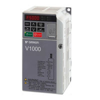
OMRON V1000 VZA 4011B User Manual (411 pages)
Compact Vector Control Drive 200 V Class Three-Phase Input 0.1 to 15 kW, 200 V Class Single-Phase Input 0.1 to 4.0 kW, 400 V Class Three-Phase Input 0.2 to 15 kW
Brand:
OMRON
| Category:
Amplifier
| Size: 20.44 MB
Table of Contents
Table of Contents
4
Preface & General Safety
12
Preface
13
Applicable Documentation
13
I.1 Preface
13
Symbols
13
Terms and Abbreviations
13
General Safety
14
I.2 General Safety
14
Safety Messages
14
Supplemental Safety Information
14
Drive Label Warnings
16
Warranty Information
16
Quick Reference
17
1 Receiving
18
Section Safety
19
Model Number and Nameplate Check
20
Nameplate
20
Drive Models and Enclosure Types
22
Component Names
23
Ip20/Open-Chassis
23
IP20/NEMA Type 1 Enclosure
25
Front Views
26
2 Mechanical Installation
28
Section Safety
29
Mechanical Installation
31
Installation Environment
31
Installation Orientation and Spacing
32
Removing and Attaching the Protective Covers
33
Exterior and Mounting Dimensions
33
3 Electrical Installation
38
Section Safety
39
Standard Connection Diagram
41
Main Circuit Connection Diagram
43
Single-Phase 200 V Class (VZAB0P1 ~ B4P0)
43
Three-Phase 200 V Class (VZA20P1 ~ 2015); Three-Phase 400 V Class (VZA40P2 ~ 4015)
43
Terminal Block Configuration
44
Protective Covers
45
Ip20/Open-Chassis Cover Removal and Installation
45
IP20/NEMA Type 1 Cover Removal and Installation
45
Main Circuit Wiring
47
Main Circuit Terminal Functions
47
Wire Gauges and Tightening Torque
47
Main Circuit Terminal Power Supply and Motor Wiring
49
Control Circuit Wiring
51
Control Circuit Terminal Block Functions
51
Terminal Configuration
53
Wiring Procedure
53
I/O Connections
56
Sinking/Sourcing Mode Switch
56
Main Frequency Reference
58
DIP Switch S1 Analog Input Signal Selection
58
Memobus/Modbus Termination
59
Braking Resistor
60
Installation
60
Wiring Checklist
62
4 Start-Up Programming & Operation
64
Section Safety
65
Using the Digital LED Operator
67
Keys, Displays, and Leds
67
Digital Text Display
68
LED Screen Displays
68
LO/RE LED and RUN LED Indications
68
Menu Structure for Digital LED Operator
70
The Drive and Programming Modes
71
Navigating the Drive and Programming Modes
71
Changing Parameter Settings or Values
74
Verifying Parameter Changes: Verify Menu
75
Switching between LOCAL and REMOTE
75
Parameters Available in the Setup Group
75
Start-Up Flowcharts
77
Flowchart A: Basic Start-Up and Motor Tuning
78
Subchart A1: Simple Motor Setup with Energy Savings or Speed Search Using V/F Mode
79
Subchart A2: High Performance Operation Using Open Loop Vector Motor Control
80
Subchart A3: Operation with Permanent Magnet Motors
81
Powering up the Drive
82
Powering up the Drive and Operation Status Display
82
Application Selection
83
Setting 1: Water Supply Pump Application
83
Setting 2: Conveyor Application
83
Setting 3: Exhaust Fan Application
84
Setting 4: HVAC Fan Application
84
Setting 5: Compressor Application
84
Setting 6: Hoist Application
85
Notes on Controlling the Brake When Using the Hoist Application Preset
85
Setting 7: Traveling Application
87
Auto-Tuning
88
Types of Auto-Tuning
88
Before Auto-Tuning the Drive
88
Auto-Tuning Interruption and Fault Codes
89
Performing Auto-Tuning
89
Auto-Tuning Example
90
Input Data for Auto-Tuning
91
No-Load Operation Test Run
93
Test Run with Load Connected
94
Test Run with the Load Connected
94
Verifying Parameter Settings and Backing up Changes
95
Backing up Parameter Values: O2-03
95
Parameter Access Level: A1-01
95
Password Settings: A1-04, A1-05
95
Copy Function (Optional)
95
Test Run Checklist
97
5 Parameter Details
98
A: Initialization
99
A1: Initialization
99
A2: User Parameters
102
B: Application
103
B1: Mode of Operation
103
B2: DC Injection Braking
110
B3: Speed Search
111
B4: Delay Timers
116
B5: PID Control
116
B6: Dwell Function
124
B8: Energy Saving
124
C: Tuning
126
C1: Acceleration and Deceleration Times
126
C2: S-Curve Characteristics
128
C3: Slip Compensation
128
C4: Torque Compensation
129
C5: Automatic Speed Regulator (ASR)
130
C6: Carrier Frequency
132
D: Reference Settings
135
D1: Frequency Reference
136
D2: Frequency Upper/Lower Limits
137
D3: Jump Frequency
138
D4: Frequency Hold and Up/Down 2 Function
138
D7: Offset Frequencies
143
E: Motor Parameters
145
E1: V/F Characteristics
145
E2: Motor 1 Parameters
148
E3: V/F Characteristics for Motor 2
150
E4: Motor 2 Parameters
151
E5: PM Motor Settings
153
F: Option Settings
155
F1: Error Detection for V/F Control with PG
155
F6 and F7: Serial Communications Option Card Settings
156
H: Terminal Functions
161
H1: Multi-Function Digital Inputs
161
H2: Multi-Function Output
170
H3: Multi-Function Analog Input Terminals
178
H4: Multi-Function Analog Output Terminals
183
H5: Memobus/Modbus Serial Communication
184
H6: Pulse Train Input/Output
184
L: Protection Functions
186
L1: Motor Protection Functions
186
L2: Momentary Power Loss Ride-Thru
189
L3: Stall Prevention
192
L4: Speed Agree/Frequency Reference Loss Detection
198
L5: Fault Restart
200
L6: Torque Detection
201
L7: Torque Limit
203
L8: Hardware Protection
204
N: Special Adjustments
209
N1: Hunting Prevention
209
N2: Automatic Frequency Regulator (AFR) Tuning
209
N3: High Slip Braking (Hsb)/Overexcitation Deceleration
210
N6: Motor Line-To-Line Resistance Online Tuning
211
N8: PM Motor Control
211
O: Operator Related Settings
214
O1: Display Settings and Selections
214
O2: Operator Key Selections
215
O3: Copy Function
216
O4: Maintenance Monitor Settings
217
Q: Fbds Parameters
219
R: Fbds Connection Parameters
219
T: Motor Tuning
219
U: Monitor Parameters
220
U1: Operation Status Monitors
220
U2: Fault Trace
220
U3: Fault History
220
U4: Maintenance Monitors
220
U5: PID Monitors
220
U6: Control Monitors
220
U8: Fbds Monitors
220
6 Troubleshooting
222
Section Safety
223
Motor Performance Fine Tuning
225
V/F Motor Control Method Tuning
225
Open Loop Vector (OLV) Motor Control Method Tuning
225
Motor Hunting and Oscillation Control Parameters
226
Drive Alarms, Faults, and Errors
228
Types of Alarms, Faults, and Errors
228
Alarm and Error Displays
228
Fault Detection
231
Fault Displays, Causes, and Possible Solutions
231
Alarm Detection
242
Alarm Codes, Causes, and Possible Solutions
242
Operator Programming Errors
248
Ope Codes, Causes, and Possible Solutions
248
Auto-Tuning Fault Detection
251
Auto-Tuning Codes, Causes, and Possible Solutions
251
Diagnosing and Resetting Faults
253
Fault Occurs Simultaneously with Power Loss
253
If the Drive Still Has Power after a Fault Occurs
253
Viewing Fault Trace Data after Fault
253
Fault Reset Methods
253
Troubleshooting Without Fault Display
254
Cannot Change Parameter Settings
254
Motor Does Not Rotate Properly after Pressing RUN Button or after Entering External Run Command
254
7 Periodic Inspection & Maintenance
262
Section Safety
263
Inspection
265
Recommended Daily Inspection
265
Recommended Periodic Inspection
265
Periodic Maintenance
267
Replacement Parts
267
Drive Cooling Fans
268
Cooling Fan Replacement
268
Drive Replacement
270
Serviceable Parts
270
Terminal Board Overview
270
Replacing the Drive
270
8 Peripheral Devices & Options
274
Section Safety
275
Drive Options and Peripheral Devices
277
Connecting Peripheral Devices
278
Installing Peripheral Devices
279
Installing a Molded Case Circuit Breaker (MCCB)
279
Installing a Leakage Breaker
279
Installing a Magnetic Contactor
279
Connecting an AC or DC Reactor
280
Connecting a Surge Protector
280
Connecting a Noise Filter
280
EMC Filter Installation
282
Zero-Phase Reactor
282
Installing a Motor Thermal Overload (Ol) Relay on the Drive Output
282
Communication Options
284
Connecting an Option Card
285
Verifying the Option Card and Product Type
285
Connecting the Option Card
285
Specifications
288
Heavy Duty and Normal Duty Ratings
289
Single/Three-Phase 200 V Class Drive
290
Three-Phase 400 V Class Drives
292
Drive Specifications
293
Drive Watt Loss Data
295
Drive Derating Data
296
Carrier Frequency Derating
296
Temperature Derating
296
Altitude Derating
296
Parameter List
298
Parameter Groups
299
Parameter Table
300
A: Initialization Parameters
300
B: Application
300
C: Tuning
305
D: References
307
E: Motor Parameters
309
F: Options
313
H Parameters: Multi-Function Terminals
316
L: Protection Function
322
N: Advanced Performance Set-Up
328
O: Operator Related Parameters
330
Q: Fbds Parameters
331
R: Fbds Connection Parameters
331
T: Motor Tuning
333
U: Monitors
333
Control Mode Dependent Parameter Default Values
339
V/F Pattern Default Values
340
Defaults by Drive Capacity (O2-04) and ND/HD (C6-01)
341
Parameters that Change with the Motor Code Selection
349
Yaskawa SMRA Series SPM Motor
349
SS5 Motor: Yaskawa SSR1 Series IPM Motor
350
Memobus/Modbus Communications
352
Section Safety
353
Memobus/Modbus Configuration
354
Communication Specifications
355
Connecting to a Network
356
Network Cable Connection
356
Wiring Diagram for Multiple Connection
356
Network Termination
357
Memobus/Modbus Setup Parameters
359
Memobus/Modbus Serial Communication
359
Drive Operations by Memobus/Modbus
362
Observing the Drive Operation
362
Controlling the Drive
362
Communications Timing
363
Command Messages from Master to Drive
363
Response Messages from Drive to Master
363
Message Format
364
Message Content
364
Slave Address
364
Function Code
364
Data
364
Error Check
364
Message Examples
366
Reading Drive Memobus/Modbus Register Contents
366
Loopback Test
366
Writing to Multiple Registers
367
Memobus/Modbus Data Table
368
Command Data
368
Monitor Data
369
Broadcast Messages
374
Fault Trace Contents
374
Alarm Register Contents
375
Enter Command
376
Enter Command Types
376
Enter Command Settings When Upgrading the Drive
376
Communication Errors
377
Memobus/Modbus Error Codes
377
Slave Not Responding
377
Self-Diagnostics
378
Standards Compliance
380
Section Safety
381
European Standards
383
CE Low Voltage Directive Compliance
383
EMC Guidelines Compliance
384
UL Standards
389
UL Standards Compliance
389
Drive Motor Overload Protection
390
Safe Disable Input Precautions
392
Safe Disable Function Description
392
Installation
392
User Setting Table
393
Index
398
Advertisement
Advertisement
Related Products
Omron V1000 VZA 2011F
Omron V1000 VZA 2015F
Omron V1000 VZA 4015B
Omron V1000 Series
Omron V640-HS62
Omron V600-HAR92
Omron V700-L11
Omron V1000 VZA B0P2B
Omron V1000 VZA B2P2B
Omron V1000 VZA 20P1B
Omron Categories
Blood Pressure Monitor
Controller
Accessories
Switch
Inverter
More Omron Manuals
Login
Sign In
OR
Sign in with Facebook
Sign in with Google
Upload manual
Upload from disk
Upload from URL