Sign In
Upload
Manuals
Brands
Omron Manuals
Accessories
F3SGPGA-A
Omron F3SGPGA-A Manuals
Manuals and User Guides for Omron F3SGPGA-A. We have
2
Omron F3SGPGA-A manuals available for free PDF download: User Manual, Quick Installation Manual
Omron F3SGPGA-A User Manual (473 pages)
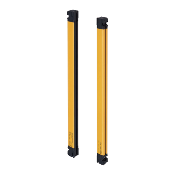
Safety Light Curtain F3SG SR Series Multi-Beam Safety Sensor
Brand:
Omron
| Category:
Security Sensors
| Size: 34.9 MB
Table of Contents
Table of Contents
19
Legislation and Standards
3
Terms and Conditions Agreement
5
Terms and Conditions Agreement (Software)
7
Safety Precautions
8
Precautions for Safe Use
14
Precautions for Correct Use
15
Visual Aids
17
Table of Contents
19
Chapter1 Overview And Specifications
31
What Is Included
32
System Components
33
2-12-4.Setting with SD Manager
33
Setting with SD Manager
33
How to Update SD Manager
33
Downloading SD Manager
33
Installing SD Manager
33
List of Key Features
36
Model Overview
36
List of Key Features
38
LED Indicators on F3SG-SR/PG
40
Ratings and Specifications
45
F3SG-SR Series
45
F3Sg
50
F3SG-SR IP69K Model
54
Intelligent Tap
59
Bluetooth® Communication Unit
60
List of Models
61
List of Models and Response Times
61
F3Sg-Sr
61
F3Sg
64
F3SG-SR IP69K Model
65
List of Models, Current Consumption and Weight
66
F3Sg-Sr
66
F3Sg
70
F3SG-SR IP69K Model
70
Calculation of Response Time of Cascaded Segments
72
Chapter 2 System Operation and Functions
75
Combination of Functions
77
Operating States
79
Operating States of F3SG-SR/PG and Intelligent Tap
79
Operating States of Intelligent Tap
80
Mutual Interference Prevention
81
Mutual Interference Prevention of F3SG-SR/PG
81
Optical Synchronization
81
Wired Synchronization
84
Overview
85
PNP/NPN Selection
85
Setting with Intelligent Tap
85
Setting with SD Manager
85
Overview
86
Self-Test
86
Self-Test Details
86
Waveform of Safety Outputs
87
External Test
88
Overview
88
Factory Default Setting
89
Setting with Intelligent Tap
89
Setting with SD Manager
89
Lockout Reset
90
Interlock
91
Over View
91
Factory Default Setting
93
Setting with Intelligent Tap
93
Setting with SD Manager
93
Overview
94
Pre-Reset
94
Factory Default Setting
95
Setting with Intelligent Tap
96
Setting with SD Manager
96
2-10-1.Overview
97
Psdi
97
2-10-2.Factory Default Setting
99
2-10-3.Setting Change Using Intelligent Tap
99
2-10-4.Setting Change Using SD Manager
99
2-11-1.Overview
100
External Device Monitoring (EDM)
100
2-11-2.Factory Default Setting
101
2-11-3.Setting with Intelligent Tap
101
2-11-4.Setting with SD Manager
102
2-12-1.Overview
103
Auxiliary Output
103
2-12-2.Factory Default Setting
104
2-12-3.Setting with Intelligent Tap
104
2-13-1.Overview
107
Muting
107
2-13-2.Standard Muting Mode
109
Overview
109
Installation Example 1 of Standard Muting Mode (Using Two Muting Sensors)
112
2-13-3.Exit-Only Muting Mode
119
Overview
119
Installation Example of Exit-Only Muting Mode
121
2-13-4.Position Detection Muting Mode
124
Overview
124
Installation Example of Position Detection Muting Mode
126
2-13-5.Dynamic Muting
128
2-13-6.Factory Default Setting
129
2-13-7.Setting with Intelligent Tap
129
2-13-8.Setting with SD Manager
129
2-14-1.Overview
131
Override
131
2-14-2.Override at Normal Operation
133
2-14-3.Override Upon Startup
136
2-14-4.Setting with Intelligent Tap
137
2-14-5.Setting with SD Manager
137
2-15-1.Overview
138
Fixed Blanking
138
2-15-2.Factory Default Setting
142
2-15-3.Setting with Intelligent Tap
143
2-15-4.Setting with SD Manager
143
2-16-1.Overview
144
Floating Blanking
144
2-16-2.Factory Default Setting
148
2-16-3.Setting with Intelligent Tap
148
2-16-4.Setting with SD Manager
148
2-17-1.Overview
149
Reduced Resolution
149
2-17-2.Factory Default Setting
150
2-17-3.Setting with Intelligent Tap
150
2-17-4.Setting with SD Manager
151
2-18-1.Overview
152
Warning Zone
152
2-18-2.Factory Default Setting
155
2-18-3.Setting with Intelligent Tap
155
2-18-4.Setting with SD Manager
155
2-19-1.Zone Adjacency Condition
156
2-19-2.Zone Overlap Condition
156
Setting Zone Adjacency Conditions
156
2-20-1.Overview
158
Operating Range Selection
158
2-20-2.Factory Default Setting
159
2-20-3.Setting with Intelligent Tap
159
2-20-4.Setting with SD Manager
159
2-21-1.Overview
160
2-21-2.Factory Default Setting
160
2-21-3.Setting with Intelligent Tap
160
2-21-4.Setting with SD Manager
160
Response Time Adjustment
160
2-22-1.Overview
161
Area Beam Indicator (ABI)
161
2-22-2.Factory Default Setting
162
2-22-3.Setting Change Using Intelligent Tap
162
2-22-4.Setting Change Using SD Manager
162
2-23-1.Overview
164
2-23-2.Factory Default Setting
164
2-23-3.Setting with Intelligent Tap
164
Designated Beam Output
164
2-23-4.Setting with SD Manager
165
2-24-1.Overview
166
2-24-2.Factory Default Setting
166
2-24-3.Setting Change Using Intelligent Tap
166
2-24-4.Setting Change Using SD Manager
166
Stable Light Threshold Adjustment
166
2-25-1.Incident Light Level Information
167
2-25-2.Ambient Light Level Information
167
Incident/Ambient Light Level Monitoring
167
Overview
167
Setting with SD Manager
167
2-26-1.Functional Description
168
Lamp
168
2-26-2.Installation to Main Unit
169
2-26-3.Factory Default Setting
169
2-26-4.Setting with Intelligent Tap
169
2-26-5.Setting with SD Manager
169
2-27-1.Overview
172
2-27-2.Error Log
172
2-27-3.Warning Log
172
Maintenance Information
172
2-27-4.Power-ON Time
173
2-27-5.Load Switching Frequency
173
2-27-6.Muting Statistics Information
174
2-27-7.Intelligent Tap Log
174
2-28-1.Overview
175
2-28-2.Readout Information
175
Operating Status Monitoring
175
2-29-1.Overview
176
2-29-2.Factory Default Setting
176
2-29-3.Setting Change Using Intelligent Tap
176
2-29-4.Setting Change Using SD Manager
176
Instantaneous Block Detection
176
Setting Recovery
177
2-31-1.Overview
178
Backup/Restoration
178
IO-Link
179
Chapter 3 Setting with Intelligent Tap
181
Functions Configurable by Intelligent Tap
183
Initial Setup Method after Purchase
183
List of Functions Configurable by Intelligent Tap and Initial Setup Method
183
Connection
184
Wiring
186
LED Indicators on Intelligent Tap
187
DIP Switch on Intelligent Tap
188
Backup/Restoration
190
Description of Functions
190
Performing Backup
191
Performing Restoration
193
Changing F3SG-SR/PG Configuration to Connect to Intelligent Tap
196
Changing F3SG-Sr/Pg's Settings with Intelligent Tap DIP Switch
196
Copy and Paste of Sensor Settings
196
DIP Switch
196
Intelligent Tap
196
Plug and Work
196
Various Usage of Backup and Restoration
196
Setting Fixed Blanking by Teach-In
197
Teach-In (Fix Blanking / Floating Blanking)
197
Setting Floating Blanking by Teach-In
202
Connection to SD Manager
206
Communication Specifications
207
Functional Description
207
IO-Link
207
Process Data
207
Service Data
210
3-10-1.Setting F3SG-SR/PG with DIP Switch
214
Intelligent Tap Application Example
214
3-10-2.Saving Sensor Setting to Intelligent Tap Using Backup Function
216
3-10-3.Applying Setting Saved in Intelligent Tap to Sensor Using Restoration
218
3-10-4.Replacing Intelligent Tap
221
Setting with DIP-SW
221
Settings Configured by Setup Information Stored in Intelligent Tap
223
Chapter 4 Setting with Sd Manager 3
227
Overview and Specifications
230
Overview of Configuration Tool
230
PC Environment
231
Smartphone Environment
231
System Environment
231
And each Device
232
Connection Method to Use Configuration Tools
232
Connection Patterns of F3SG-SR/PG, Intelligent Tap, and each Device
232
Connection Procedure When Using USB Connector
235
Connection Procedure When Using Bluetooth
236
Connection Procedure When Using Bluetooth® Communication Unit (F39-SGBT)
236
Connected
240
SETTING State of F3SG-SR/PG with SD Manager
240
SETTING State of F3SG-SR/PG with SD Manager 3 Connected
240
Basic Operation of SD Manager
242
Downloading SD Manager
242
How to Install/Uninstall SD Manager
242
Installing SD Manager
242
How to Uninstall SD Manager
244
And Shutting down
245
Getting Started
245
Getting Started, Description on Top Page and each Button, and Shutting down
245
How to Update SD Manager
245
Installing Driver of Intelligent Tap
245
Description on Top Page and each Button
246
Displaying/Hiding Docked Windows
248
Shutting down
248
Creating New Configuration File
249
Starting SD Manager 3 Offline
249
Reading Configuration from PC
250
Saving New Configuration File to PC
250
Switching Offline to Online
250
Logging in
251
Logging In/Logging out
251
Logging out
253
Access Restriction
254
Changing Password
254
Confirming Lot No. of Intelligent Tap
254
Forgot the Password
254
Password Protection
254
Resetting the Initial Password to "0000
255
Reading Configuration from Intelligent Tap
256
Reading/Saving/Writing Configuration of Intelligent Tap
256
Saving Configuration of Intelligent Tap in PC
256
Writing Configuration into Intelligent Tap
257
Viewing Current Configuration
259
Safety Distance Calculation
260
Changing Settings with SD Manager
261
Preparing to Change Settings
261
I/O Settings
262
Interlock/External Device Monitoring (EDM)/PSDI
262
Reset Input Time
263
Teach-In Input
264
External Test Input
265
Auxiliary Output/Lamp
266
Auxiliary Output/Lamp Setting
266
Designated Beam Output
268
Area Beam Indicator (ABI)
271
Fixed Blanking
273
Safety Function Setting
273
Floating Blanking
276
Muting/Override
278
Pre-Reset
283
Reduced Resolution
284
Warning Zone
285
Psdi
287
Operating State Setting
288
Response Time Change
288
Stable Light Threshold Adjustment
289
Operating Range Selection
290
Initializing F3SG-SR
291
Setting Initialization
291
Initializing Settings of Intelligent Tap (F39-SGIT-IL3)
292
Incident Light/Ambient Light
293
Monitoring
293
Monitoring with SD Manager
293
Operating Status Monitoring
295
Muting Statistics Information
297
Error Log Information
301
Maintenance Information
301
Warning Log
303
Intelligent Tap Log
304
Power-On Time/Load Switching Frequency
305
Instantaneous Block Detection Information
307
Basic Operation of SD Manager 3 Mobile APP
308
How to Install/Uninstall SD Manager 3 Mobile APP
308
How to Update SD Manager 3 Mobile APP
308
Installing SD Manager 3 Mobile APP
308
Pairing (Connection Verification)
308
Uninstalling SD Manager 3 Mobile APP
308
Getting Started
309
Getting Started, Main Screen, Version Confirmation, and Shutting down
309
Main Screen
311
Version Information
312
Shutting down
313
Incident/Ambient Light Level Monitoring
314
Monitoring with SD Manager
314
Status Monitoring Information
315
Maintenance Information
317
Chapter 5 Wiring and Installation
319
Detection Zone and Approach
322
Installation Considerations
322
Safety Distance
324
Safety Distance Formulas According to ISO 13855/EN ISO 13855
324
Safety Distance Formulas According to ANSI B11.19
328
Distance from Reflective Surfaces
329
F3SG-SR/PG (Type 2 ESPE)
329
Mutual Interference Prevention
330
Brackets) (F39-LSGF)
331
Dimensions
331
F3SG-SR Series
331
Mounted with Side-Mount Brackets
331
Mounted with Side-Mount Brackets (Intermediate Brackets) (F39-LSGF)
331
(Intermediate Brackets) (F39-LSGA)
333
Mounted with Adjustable Side-Mount Brackets
333
Mounted with Adjustable Side-Mount Brackets (Intermediate Brackets) (F39-LSGA)
333
(Intermediate Brackets) (F39-LSGF)
335
And Side-Mount Brackets (Intermediate Brackets) (F39-LSGF)
335
Mounted with Adjustable Top/Bottom Brackets
335
Mounted with Adjustable Top/Bottom Brackets (F3SJ, F3SN Adapter) (F39-LSGTB-SJ)
335
And Adjustable Side-Mount Brackets (Intermediate Brackets) (F39-LSGA)
337
Mounted with Adjustable Top/Bottom Brackets
337
Mounted with Adjustable Top/Bottom Brackets (F3SJ, F3SN Adapter) (F39-LSGTB-SJ)
337
Brackets) (F39-LSGF)
339
F3Sg
339
Mounted with Side-Mount Brackets
339
Mounted with Side-Mount Brackets (Intermediate Brackets) (F39-LSGF)
339
(Intermediate Brackets) (F39-LSGA)
341
Mounted with Adjustable Side-Mount Brackets (Intermediate Brackets) (F39-LSGA)
341
Adjustable Side-Mount Bracket (Intermediate Bracket) (F39-LSGA, Sold Separately)
342
(Intermediate Bracket) (F39-LSGF)
343
Adjustable Top/Bottom Bracket (F3SJ, F3SN Adapter) (F39-LSGTB-SJ, Sold Separately)
343
And Side-Mount Bracket (Intermediate Bracket) (F39-LSGF)
343
And Adjustable Side-Mount Bracket (Intermediate Bracket) (F39-LSGA)
345
Bracket
347
Side-Mount Bracket (Intermediate Bracket) (F39-LSGF Sold, Separately)
347
Adjustable Top/Bottom Bracket (F3SG-RA/RE Adapter)
348
Adjustable Top/Bottom Bracket (MS4800, F3SR Adapter)
348
Rately)
348
Intelligent Tap
349
Intelligent Tap Bracket
349
Bluetooth® Communication Unit
351
Spatter Protection Cover
352
Lamps
353
Muting Sensor Arm Mounter
354
5-2-10.Floor Mounting Column
355
5-2-11.Mirror Columns
357
5-2-12.IP69K Model
359
Mounting
361
Mounting Method
361
Number of Brackets Required
361
Proper Mounting
362
Proper Mounting Orientation
362
(F39-Lsgf)
364
Mounting Procedure
364
Mounting with Side-Mount Brackets (Intermediate Brackets)
364
Mounting with Adjustable Side-Mount Brackets (Intermediate Brackets) (F39-LSGA)
365
And Side-Mount Brackets (Intermediate Brackets) (F39-LSGF)
369
Mounting with Adjustable Top/Bottom Brackets (F3SJ, F3SN Adapter) (F39-LSGTB-SJ)
369
And Adjustable Side-Mount Brackets (Intermediate Brackets) (F39-LSGA)
373
Mounting IP69K Model
378
Beam Alignment Procedure
381
Wiring
382
Wiring Precautions
382
Power Supply Unit
383
Cable Connections
384
Root-Straight Cable
386
Root-Plug Cable for Extended
387
Extended Socket-Straight Cable
388
Extended Plug-Socket Cable
389
Cascading Cable for Extended
391
Side-By-Side Cascading Cable
392
F3SJ-B/A Conversion Cable
393
F3SG-RE Conversion Cable
395
MS48 Conversion Cable
396
Extending Cable Length with Commercially Available Cable
397
Reduced Wiring Connector System with Y-Joint Plug/Socket Connector
398
Easy Wiring Connector System with Reset Switch Connector
399
Reduced Wiring System with Muting Connector Box
401
Wiring of IP69K Model
403
Functional Earth Connection
404
Cascade Connection
405
Overview
405
Connection Procedure
407
Chapter 6 Input/Output Circuit and Applications
409
Entire Circuit Diagram
410
F3SG-SR and F3SG-PGA-A/-L
410
Input/Output Circuit
410
F3Sg-Pga-C
411
Input Circuit Diagram by Function
412
Auto Reset Mode with Optical Synchronization and EDM Unused
413
Non-Muting System Wiring Examples
413
Unused
413
Wiring Examples (for F3SG-SR/PG)
413
Auto Reset Mode with Wired Synchronization and EDM Unused
415
Unused
415
Auto Reset Mode with Optical Synchronization and EDM Used
416
Used
416
Manual Reset Mode with EDM
417
Connector
418
Manual Reset Mode with EDM and Y-Joint Plug/Socket Connector
418
Manual Reset Mode with Intelligent Tap
419
Manual Reset Mode with Reset Switch Connector
420
Pre-Reset Mode with EDM Unused
421
Pre-Reset Mode with Reset Switch Connector
422
Single Break with EDM and Intelligent Tap
423
Double Break with EDM
424
Muting System Wiring Examples
425
Standard Muting Mode/Exit-Only Muting Mode
425
Joint Plug
426
Standard Muting Mode/Exit-Only Muting Mode with Y-Joint Plug
426
Intelligent Tap
427
Standard Muting Mode/Exit-Only Muting Mode with Intelligent Tap
427
Standard Muting Mode/Exit-Only Muting Mode with Reset Switch Connector
428
Switch Connector
428
Connectable Safety Control Units
429
Chapter7 Checklists
431
Pre-Operation Checklists
432
Checklists
432
Installation Condition Check
432
Wiring Check before Power Is Turned on
432
Operation Check While the Machine Is Stopped
433
Checking that Hazardous Parts Stop While the Machine Operates
434
Maintenance Checklists
435
Checklists
435
Inspection at Startup and When Changing Operators
435
Checking that Hazardous Parts Stop While the Machine Operates
436
Items to Inspect Every 6 Months or When Machine Settings Are Changed
436
Chapter8 Appendix
439
Troubleshooting
440
LED Indicators
440
LOCKOUT State
442
Description
442
Troubleshooting
443
Warning
449
Description
449
Troubleshooting
449
Muting Sequence Error Indication
450
Interlock Sequence Error Indication
451
PSDI Sequence Error Indication
452
Troubleshooting for Intelligent Tap
453
Troubleshooting for Bluetooth® Communication Unit
456
Optional Accessories (Sold Separately)
457
Glossary
468
Revision History
472
Advertisement
Omron F3SGPGA-A Quick Installation Manual (20 pages)
Safety Multi-Light Beam
Brand:
Omron
| Category:
Accessories
| Size: 5.15 MB
Table of Contents
English
1
Table of Contents
1
1 What Is Included
2
2 System Components
3
3 F3SG-PG Setup Procedure Example
3
4 Setting with End Cap
4
5 Entire Circuit Diagram
4
6 Wiring Examples
5
Non Muting System Wiring Example (Auto Reset Mode with EDM Unused)
5
Muting System Wiring Examples (Standard Muting Mode/Exit-Only Muting Mode)
5
7 Mounting
6
Mounted with Side-Mount Brackets (Intermediate Brackets) (F39-LSGF)
6
8 Operation Check
8
Suitability for Use/Contact Information
12
日本語
13
1 同梱物のご確認
14
2 各部の名称
15
3 セットアップ手順
15
4 終端キャップ設定
16
5 入出力回路図(全体回路図
16
6 配線例
17
ミューティングを使用しない配線例(オートリセットモード、Edm 未使用
17
モード
17
7 取り付け
18
標準金具(中間金具兼用) (形 F39-Lsgf)を取り付ける場合
18
8 動作チェック
20
ご承諾事項 / お問い合わせ先
20
Advertisement
Related Products
Omron F3SG-PGA-L
Omron F3SG-PGA-C
Omron F3S-TGR-SB2-K3C-800MTL
Omron F3S-TGR-SB4-K2C-500MTL
Omron F3S-TGR-SB4-K3C-800MTL
Omron F3SJ-A0299N14
Omron F3SJ-A1265P20
Omron F3SJ-A0395P30
Omron F3SJ-A2470P55
Omron F3SJ-A0720N55
Omron Categories
Blood Pressure Monitor
Controller
Accessories
Switch
Inverter
More Omron Manuals
Login
Sign In
OR
Sign in with Facebook
Sign in with Google
Upload manual
Upload from disk
Upload from URL