Sign In
Upload
Manuals
Brands
Omron Manuals
Security Sensors
F3SG-2RE0160P14
Omron F3SG-2RE0160P14 Manuals
Manuals and User Guides for Omron F3SG-2RE0160P14. We have
1
Omron F3SG-2RE0160P14 manual available for free PDF download: User Manual
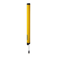
Omron F3SG-2RE0160P14 User Manual (268 pages)
Safety Light Curtain
Brand:
Omron
| Category:
Security Sensors
| Size: 8.77 MB
Table of Contents
Terms and Conditions Agreement
5
Safety Precautions
7
Precautions for Safe Use
13
Precautions for Correct Use
14
Visual Aids
15
Table of Contents
17
Chapter1 Overview And Specifications
25
What Is Included
26
System Components
27
Basic Components
28
Model Overview
29
List of Features
30
Model Overview
30
Versions
30
List of Features
31
LED Indicators
33
LED Indicator Status
34
Ratings/Specifications
36
List of Models
40
List of Models/Response Time/Current Consumption/Weight
40
Calculation of Response Time of Cascaded Segments
43
Chapter2 System Operation and Functions
45
Combination of Functions
47
Operating States
49
Machine Run State
49
Machine Stop State
49
Interlock State
49
Lockout State
49
Teach-In Mode
49
Setting State
50
Optical Synchronization
51
Overview
51
Scan Code Selection
52
Overview
52
Factory Default Setting
52
Setting with DIP Switch
52
Setting with Configuration Tool
52
PNP/NPN Selection
53
Overview
53
Factory Default Setting
53
Setting with DIP Switch
53
Setting with Configuration Tool
53
Self-Test
54
Overview
54
Self-Test Details
54
Waveform of Safety Outputs
55
External Test
56
Overview
56
Factory Default Setting
57
Setting with DIP Switch
57
Setting with Configuration Tool
57
Lockout Reset
58
Overview
58
Interlock
59
Over View
59
Factory Default Setting
62
Setting with DIP Switch
62
Setting with Configuration Tool
63
External Device Monitoring (EDM)
64
2-10-1.Overview
64
2-10-2.Factory Default Setting
65
2-10-3.Setting with DIP Switch
65
2-10-4.Setting with Configuration Tool
65
Muting
65
Auxiliary Output
67
2-11-1.Overview
67
2-11-2.Factory Default Setting
68
2-11-3.Setting with DIP Switch
68
2-11-4.Setting with Configuration Tool
69
Muting
71
2-12-1.Standard Muting Mode
73
2-12-2.Exit-Only Muting Mode
83
2-12-3.Position Detection Muting Mode
89
2-12-4.Dynamic Muting
93
2-12-5.Factory Default Setting
94
2-12-6.Setting with DIP Switch
94
2-12-7.Setting with Configuration Tool
94
Override
96
2-13-1.Override at Normal Operation
97
2-13-2.Override Upon Startup
99
2-13-3.Setting with DIP Switch
100
2-13-4.Setting with Configuration Tool
100
Fixed Blanking
101
2-14-1.Overview
101
2-14-2.Factory Default Setting
104
2-14-3.Setting with DIP Switch
104
2-14-4.Setting with Configuration Tool
104
Floating Blanking
105
2-15-1.Overview
105
2-15-2.Factory Default Setting
108
2-15-3.Setting with DIP Switch
108
2-15-4.Setting with Configuration Tool
109
Reduced Resolution
110
2-16-1.Overview
110
2-16-2.Factory Default Setting
111
2-16-3.Setting with DIP Switch
111
2-16-4.Setting with Configuration Tool
111
Warning Zone
113
2-17-1.Overview
113
2-17-2.Factory Default Setting
116
2-17-3.Setting with DIP Switch
116
2-17-4.Setting with Configuration Tool
116
Setting Zone Adjacency Conditions
117
Operating Range Selection
119
2-19-1.Overview
119
2-19-2.Factory Default Setting
119
2-19-3.Setting with DIP Switch
119
2-19-4.Setting by Wiring
120
2-19-5.Setting with Configuration Tool
120
Response Time Adjustment
121
2-20-1.Overview
121
2-20-2.Factory Default Setting
121
2-20-3.Setting with DIP Switch
121
2-20-4.Setting with Configuration Tool
121
Lamp
122
2-21-1.Overview
122
2-21-2.Factory Default Setting
122
2-21-3.Setting with DIP Switch
122
2-21-4.Setting with Configuration Tool
122
Designated Beam Output
125
2-22-1.Overview
125
2-22-2.Factory Default Setting
125
2-22-3.Setting with DIP Switch
126
2-22-4.Setting with Configuration Tool
126
Light Level Monitoring
127
2-23-1.Incident Light Level Information
127
Overview
127
Setting with Configuration Tool
127
2-23-2.Ambient Light Level Information
127
Maintenance Information
128
2-24-1.Overview
128
2-24-2.Error Log
128
2-24-3.Warning Log
128
2-24-4.Power-ON Time
128
2-24-5.Load Switching Frequency
129
2-24-6.Muting Statistics Information
129
Operating Status Monitoring
130
2-25-1.Overview
130
2-25-2.Readout Information
130
Setting Recovery
131
2-26-1.Overview
131
Chapter3 Setting With DIP Switch
133
List of Features Configurable by DIP Switch
134
DIP Switch
135
DIP Switch on Receiver
136
DIP Switch on Emitter
137
Push Switch
137
Setting by Teach-In
138
Setting Fixed Blanking by Teach-In
138
Setting Floating Blanking by Teach-In
141
Chapter4 Wiring/Installation
145
Installation Considerations
147
Detection Zone and Approach
147
Safety Distance
148
Safety Distance Formulas According to ISO 13855/EN ISO 13855
148
Safety Distance Formulas According to ANSI B11.19
151
Distance from Reflective Surfaces
152
F3SG-4R (Type 4 ESPE)
152
F3SG-2R (Type 2 ESPE)
152
Mutual Interference Prevention
153
Cascade Connection
155
Overview
155
Connection Procedure
157
Dimensions
158
Mounted with Standard Fixed Brackets (F39-LGF)
158
F3SG-RA Series
158
Mounting
158
F3SG-RE Series
160
Standard Fixed Bracket
162
Mounted with Standard Adjustable Brackets (F39-LGA)
163
F3SG-RA Series
163
F3SG-RE Series
165
Standard Adjustable Bracket
167
(F39-Lga)
168
F3SG-RA Series
168
F3SG-RE Series
174
Top/Bottom Adjustable Bracket (F39-LGTB)
178
Top/Bottom Adjustable Bracket (F39-LGTB-1)
178
Mounting
179
Mounting Method
179
Number of Brackets Required
179
Mounting Procedure
180
Mounting with Standard Fixed Brackets (F39-LGF)
180
Mounting with Standard Adjustable Brackets (F39-LGA)
181
Mounting with Top/Bottom Adjustable Brackets (F39-LGTB)
185
Beam Alignment Procedure
188
Wiring
189
Wiring Precautions
189
Power Supply Unit
190
Cable Connections(F3SG-RA Series)
191
Single-Ended Cable
191
Double-Ended Cable
192
Cascading Cable
194
Extending Cable Length with Commercially Available Cable
195
Adapter Cable (A)
195
Adapter Cable (B)
197
Reduced Wiring Connector System with Y-Joint Plug/Socket Connector
199
Reduced Wiring Connector System with 4-Joint Plug/Socket Connector
200
Cable Connections(F3SG-RE Series)
203
Recommended Cable
203
Extending Cable Length with Commercially Available Cable
204
Adapter Cable (C)
204
Reduced Wiring Connector System
206
Functional Earth Connection
207
Chapter5 Input/Output Circuit and Applications
209
Input/Output Circuit
211
Entire Circuit Diagram
211
F3SG-RA Series
211
F3SG-RE Series
213
Input Circuit Diagram by Function
215
F3SG-RA Series
215
F3SG-RE Series
215
Wiring Examples(F3SG-RA Series)
216
Standalone F3SG-RA Using PNP Outputs
216
Auto Reset Mode, EDM Disabled and PNP Outputs
216
Manual Reset Mode, EDM Enabled and PNP Outputs
217
Y-Joint Plug/Socket Connector Using PNP Outputs
218
Pre-Reset Mode Using PNP Output
219
Muting Using PNP Outputs
220
Standard Muting Mode/Exit-Only Muting Mode Using PNP Outputs
220
Mode Using PNP Outputs
221
Puts
222
Standard Muting Mode with Four Muting Sensors Using PNP Outputs
223
Standard Muting Mode with F3W-MA
224
Connector)
224
Exit-Only Muting Mode with F3W-MA
225
Connector)
225
Standalone F3SG-RA Using NPN Outputs
226
Auto Reset Mode, EDM Disabled and NPN Outputs
226
Manual Reset Mode, EDM Enabled and NPN Outputs
227
Y-Joint Plug/Socket Connector Using NPN Outputs
228
Pre-Reset Mode Using NPN Output
229
Muting Using NPN Outputs
230
Standard Muting Mode/Exit-Only Muting Mode Using NPN Outputs
230
Puts
231
Standard Muting Mode with Four Muting Sensors Using NPN Outputs
232
Wiring Examples (F3SG-RE Series)
233
Short Mode
233
Long Mode
234
Standalone F3SG-RE with Y-Joint Plug/Socket Connector
235
Connectable Safety Control Units
236
Chapter6 Checklists
237
Pre-Operation Checklists
238
Checklists
238
Installation Condition Check
238
Wiring Check before Power Is Turned on
238
Operation Check While the Machine Is Stopped
239
Checking that Hazardous Parts Stop While the Machine Operates
240
Maintenance Checklists
241
Checklists
241
Inspection at Startup and When Changing Operators
241
Checking that Hazardous Parts Stop While the Machine Operates
242
Items to Inspect Every 6 Months or When Machine Settings Are Changed
242
Chapter7 Appendix
245
Troubleshooting
246
Lockout State
247
Description
247
Troubleshooting
248
Warning
252
Description
252
Troubleshooting
252
Muting Sequence Error Indication
253
Interlock Sequence Error Indication
254
Optional Accessories(Sold Separately)
255
Glossary
263
Revision History
267
Advertisement
Advertisement
Related Products
Omron F3SG-2RE0190P30
Omron F3SG-2RE0430P30
Omron F3SG-2RE0240P14
Omron F3SG-2RE0510P30
Omron F3SG-2RE0720P14
Omron F3SG-2RE0910P30
Omron F3SG-2RE0560P14
Omron F3SG-2RE0400P14
Omron F3SG-2RE0350P30
Omron F3SG-2RE0320P14
Omron Categories
Blood Pressure Monitor
Controller
Accessories
Switch
Inverter
More Omron Manuals
Login
Sign In
OR
Sign in with Facebook
Sign in with Google
Upload manual
Upload from disk
Upload from URL