Motorola Astro APX 3000 Manuals
Manuals and User Guides for Motorola Astro APX 3000. We have 7 Motorola Astro APX 3000 manuals available for free PDF download: Detailed Service Manual, Basic Service Manual, User Manual, Manual, Quick Start Manual, Quick Reference Card
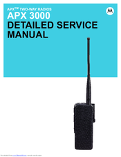
Motorola Astro APX 3000 Detailed Service Manual (474 pages)
Brand: Motorola
|
Category: Two-Way Radio
|
Size: 31 MB
Table of Contents
-
Foreword
3 -
-
Main Board28
-
Controller47
-
Bluetooth74
-
-
-
-
RX Audio Error113
-
TX Audio Error114
-
Keyload Failure115
-
RX RF Failure117
-
5.11 FGU Failure127
-
VCO Failure129
-
5.13 GPS Failure133
-
PA Failure141
-
-
-
-
Advertisement
Motorola Astro APX 3000 Basic Service Manual (144 pages)
Brand: Motorola
|
Category: Two-Way Radio
|
Size: 15 MB
Table of Contents
-
Foreword
3 -
-
-
Rf Test Mode48
-
-
Test Setup55
-
Softpot56
-
-
-
Radio Reassembly101
-
-

Motorola Astro APX 3000 User Manual (104 pages)
Brand: Motorola
|
Category: Two-Way Radio
|
Size: 9 MB
Table of Contents
-
Disclaimer
16 -
-
Body28
-
-
-
Helpful Tips
84 -
Accessories
89
Advertisement

Motorola Astro APX 3000 User Manual (98 pages)
Brand: Motorola
|
Category: Two-Way Radio
|
Size: 9 MB
Table of Contents
-
Disclaimer
16 -
-
Body28
-
-
-
Helpful Tips
79 -
Accessories
84

Motorola Astro APX 3000 Manual (59 pages)
RF ENERGY EXPOSURE AND PRODUCT SAFETY
GUIDE FOR PORTABLE TWO-WAY RADIOS
Brand: Motorola
|
Category: Two-Way Radio
|
Size: 4 MB
Table of Contents

Motorola Astro APX 3000 Quick Reference Card (2 pages)
Brand: Motorola
|
Category: Portable Radio
|
Size: 2 MB
Table of Contents

Motorola Astro APX 3000 Quick Start Manual (2 pages)
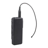
Digital Portable Radios Flexible Antenna