Sign In
Upload
Manuals
Brands
Mercury Manuals
Outboard Motor
2A456613
Mercury 2A456613 Manuals
Manuals and User Guides for Mercury 2A456613. We have
1
Mercury 2A456613 manual available for free PDF download: Service Manual
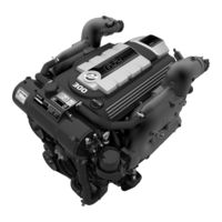
Mercury 2A456613 Service Manual (566 pages)
Brand:
Mercury
| Category:
Outboard Motor
| Size: 84 MB
Table of Contents
Important Information, Maintenance, and 1
7
Table of Contents
7
Serial Number Decal Placement
8
Introduction
8
Engine Serial Number
8
Directional References
9
Seacore
9
Seacore Components and Castings
9
Stainless Steel Fasteners
9
Proper Break
9
20-Hour Break-In Period
9
Gasoline Containing Alcohol
10
Using Reformulated (Oxygenated) Gasoline (USA Only)
10
Fuel Ratings
10
After the Break-In Period
10
Fuel Requirements
10
Engine Oil
11
Important Information, Maintenance, and 1
17
6.2 MPI ECT and 6.2 MPI Non-ECT
19
Engine
19
Engine and Tune-Up Specifications
19
Fluid Specifications
19
Notes on Engine Specifications
19
Maintenance Intervals
20
Maintenance Schedule-Inboard Models
20
Power-Assisted Steering and Power Trim Fluids
20
Routine Maintenance
20
Scheduled Maintenance
20
Maintenance Schedule-Towsport Models
21
Routine Maintenance
21
Scheduled Maintenance
21
Maintenance Schedule-Sterndrive Models
22
Routine Maintenance
22
Scheduled Maintenance
23
Checking and Filling the Engine Oil
24
Engine Oil
24
Changing the Engine Oil and Filter
25
Transmission Fluid
27
Changing
29
Checking
29
Filling
29
Power Trim Fluid
29
Flame Arrestor
30
Serpentine Drive Belt
31
Inspection and Routing
32
Replacing Belt
32
Fuel System
33
Water-Separating Fuel Filter
33
Changing Coolant
35
Checking Coolant Level
35
Cleaning and Inspection
35
Closed-Cooling System
35
Power-Assisted Steering Fluid
35
Power-Assisted Steering Fluid-Sterndrive Only
35
Changing
37
Compact Hydraulic Steering
37
Bravo Sterndrive Gear Lube
38
Checking
38
Filling
38
System Check
38
Changing
39
Battery
40
Electrical System
40
Exhaust System
40
Instruments
40
Remote Control
40
Visual Inspections
40
Seawater Pump
41
Steering System Lubrication
41
Corrosion Prevention
42
Maintaining Ground Circuit Continuity
42
Mercathode
44
Power Package Exterior Surfaces
44
Cleaning the Seawater Strainer, if Equipped
45
Seawater System
45
Air Actuated Single-Point Drain System (Closed Cooling, Inboard Models)
46
Checking the Seawater Pickups
46
Draining the Raw Water
46
Draining the Seawater System
46
Air Actuated Single-Point Drain System (Standard Cooling)
49
Air Actuated Single-Point Drain System-Bravo Seawater Cooling
52
Draining the Sterndrive
54
Air Actuated Single-Point Drain System (Closed Cooling)
55
Draining the Raw Water
55
Draining the Seawater System
55
Air Actuated Single-Point Drain System (Closed Cooling, Inboard Models)
58
Flushing the Power Package
61
Flushing the Power Package (Bravo)
61
Seacore Power Package Flushing Procedure
64
Cold Weather or Extended Storage
67
Preparing Power Package for Storage-MPI Models
67
Power Package Recommissioning
68
Important Information, Maintenance, and 1
71
Before You Begin Troubleshooting
72
General Troubleshooting Guidelines
72
Introduction
72
Situational Awareness
72
Visual/Physical Check
73
Diagnostic Roadmap
74
Emission Control Fault Indicators
74
Chart R1: Engine System Fails to Power
75
Chart R2: OBD-M Lamp Does Not Self-Test
76
Chart R3: Crankshaft Fails to Rotate
77
Chart R4: Engine Cranks over but will Not Start
78
Chart R5: Hard Start
79
Chart R6: Engine Stalls
80
Chart S1: Engine Surges
81
Chart S2: Lack of Power, Sluggish, or Spongy
81
Diagnosis by Symptom
81
Chart S3: Detonation or Spark Knock
82
Chart S4: Hesitation, Sag, or Stumble
84
Chart S5: Engine Misses
85
Chart S6: Rough, Unstable, or Incorrect Idle and Stalling
86
Chart S7: Poor Fuel Economy
86
Chart S8: Dieseling or Run
87
Chart S9: Backfire
88
Chart T1: Main Power Relay Test
89
Troubleshooting Tests
89
Chart T2: Fuel System Electrical Test
90
Chart T3: Fuel System Diagnosis
90
Chart T4: Ignition System Test
91
CDS G3 Service Tool
92
Connecting and Starting G3
92
Default Sensor Values
92
Fault Conditions
92
Introduction
92
OBD-M Faults
92
PCM 112 Calibration Information
92
Sticky and Nonsticky Faults
92
Troubleshooting Shift Problems
92
CDS G3 Service Tool Home Screen Overview
94
CDS G3 Fault List
95
Removal and Installation 2
97
Disconnecting the Fluid Systems
98
Fuel Hose
98
Preparation
98
Steering Hoses (Sterndrive)
98
Gear Lube Monitor (Sterndrive)
99
Seawater Hoses
99
Disconnecting the Shift Cable and Throttle Cable
100
Disconnecting the Electrical Components
101
Continuity Wire Removal (Sterndrive)
102
Removing the Engine
102
Removal and Installation 2
105
Preparation
107
Torque Specifications
107
Engine Installation and Alignment (Sterndrive)
108
Shift Cable Routing
108
Bravo Seawater Inlet Fitting Connection
113
Connecting the Fluid Systems
113
Gear Lube Monitor Connection
113
Power-Assisted Steering Hoses
116
Speedometer and Pitot Connections
116
Bravo Models Remote Control Shift Cable Adjustment
117
Bravo Models Shift Cable Installation
117
Bravo Shift Cable Installation and Adjustment
117
Throttle Cable Installation
119
Connecting the Electrical Components
120
Electrical Connections
120
Engine Harness Connections
120
Continuity Wire Connection
121
Quick-Connect Mercathode System Connection
121
Battery Connection
123
Installing the Sterndrive Unit
123
Trim Position Sender Connections
123
Troubleshooting Shift Problems
123
Wire Color Code Abbreviations
123
Power Trim System
124
Boat Harness Connector to Engine
125
Boat Harness Installation Guidelines-MPI Sterndrive
125
Key Switch Connector
125
Trim Switch
126
Accessory Relay Connection
127
Additional Relay Kit
127
Lanyard Stop Switch
127
Neutral Safety Switch
127
Optional E-Stop
127
Warning Horn
127
CAN P (CAN 1) Connections
128
General Repower Information
128
Transom Ground Connection
129
Transom Harness-Dts/Mechanical Shift
129
Bravo Sterndrive Shift Check (Engine Running)
130
Engine Installation and Initial Engine Alignment-Towsport, Inboard
131
Engine Mount Preadjustment
131
Models with 8 Degree Down-Angle Transmissions
134
Models with V-Drive Transmissions
134
Final Engine Alignment-Towsport, Inboard
135
Exhaust System Guidelines-Towsport
137
Exhaust System Guidelines-Inboard Models
138
Exhaust Hose Connections-Inboard
139
General Information
140
Measuring Exhaust Elbow Height-Towsport
140
Boat Requirements
141
Loading Requirements
142
Loading the Boat (Boats with a Capacity Plate)
142
Loading the Boat (Boats Without a Capacity Plate)
144
Clear Hose Measurement Method
146
Audio Warning Temperature Switch Installation-Inboard
147
Electrical Connections-Towsport, Inboard
147
Boat Harness and Instrumentation Connections-Inboard
148
Audio Warning System Connections-Towsport, Inboard
149
Smartcraft Product
149
Service Engine Light and OBD-M MIL Kit
150
Testing the OBD-M Malfunction Indicator Lamp (MIL)
150
Battery Cables Connection
151
Propeller Selection
151
Shaft Log Seal Connection
151
6.2L Maximum RPM Specification
152
Adaptive Speed Control (ASC) Propping with G3
152
Boat-In-The-Water Tests
152
Engine Idle Speed
152
Wide-Open Throttle Propping Without G3 Test
154
Checking Shift Operation
155
Engine Mechanical 3
157
Engine Block Codes
158
Identification
158
Kent-Moore
159
Tools
159
Precautions
160
External Engine Components
161
Torque Specifications
161
Crankcase Oil Dipstick Measurements
162
Engine Rotation
162
General Information
162
Repair Guidelines
162
Front Mounts
163
Rear Mounts
163
Sterndrive Engine Mounts
163
Cylinder Head and Rocker Cover Components
164
Engine Components
164
Timing Chain and Front Cover Components
166
Crankshaft and Camshaft
168
Piston and Connecting Rod
170
Intake Manifold and Fuel Rail (MPI)
172
Oil Pan and Oil Pump
174
Remote Oil Filter
176
Removal
178
Rocker Arm Cover
178
Rocker Arms and Valve Pushrods
178
Finding Top Dead Center (TDC)
179
Method 1
179
Method 2
179
Intake Manifold Assembly
180
Removal
180
Exploded View
181
Hydraulic Valve Lifters
181
Removal
181
Special Information
181
Oil Pump Drive
182
Removal
182
Flywheel and Housing
183
Flywheel Housing Removal
183
Flywheel Removal
183
Oil Pan
184
Removal
184
Front Engine Cover
185
Removal
185
Removal
187
Timing Chain and Sprockets
187
Camshaft
188
Removal
188
Cylinder Head
189
Removal
189
Valve Spring Assembly Exploded View
190
Valve Spring Assembly Removal
191
Connecting Rod, Bearings, and Piston Assembly
192
Exploded View
192
Removal
192
Disassembly
193
Rear Oil Seal
194
Removal
194
Disassembly
195
Oil Pump
195
Removal
195
Crankshaft, Main Bearings, and Engine Block
196
Exploded View
196
Removal
196
Engine Block
198
Engine Mechanical 3
203
General Specifications
204
Cylinder Bore
205
Engine Specifications
205
Oil Pump
205
Piston Bore Clearance
205
Piston Rings
205
Connecting Rod
206
Crankshaft
206
Piston Pin
206
Valve
206
Camshaft
208
Clean and Inspect
208
Flywheel
208
Timing Chain
208
Cylinder Reconditioning
209
Cylinder Boring
210
Cylinder Honing
210
Piston Selection
210
Camshaft Bearings
211
Engine Block Plugs
214
Cleaning
216
Crankshaft and Pistons
216
Main Bearing Inspection
217
Crankshaft Installation
219
Main Bearing Clearance, Plastigauge Method
222
Crankshaft End Play
223
Piston Inspection
224
Preliminary Inspection
224
Assembly
226
Piston Ring Gap Inspection
226
Piston and Rod Installation
227
Piston/Connecting Rod Assembly
227
Connecting Rod Bearing Clearance, Micrometer Method
231
Connecting Rod Bearing Clearance, Plastigauge Method
232
Inspection
234
Installation
234
Oil Pump
234
Camshaft
235
Inspection
235
Installation
236
Assembly
237
Inspection
237
Timing Chain
237
Checking Timing Chain Deflection
238
Crankcase Front Cover
239
Installation
239
Rear Seal Installation
240
Inspection
241
Oil Pan
241
Installation
242
Core Plug Installation
245
Cylinder Head
245
Inspection
246
Repair
249
Cylinder Head Reassembly
251
Installation
253
Inspection
256
Lifters
256
Inspection
257
Installation
257
Lifter Installation
257
Oil Pump Drive
257
Inspection
258
Rocker Arms and Pushrods
258
Installation
259
Installation
261
Intake Manifold
261
Intake Manifold Assembly
261
Cleaning and Inspection
264
Flywheel
264
Installation
264
Rocker Arm Cover
264
Cleaning
267
Flywheel Housing
267
Inspection
267
Installation
267
Oil Lines
268
Crankcase Front Cover Oil Seal (Without Removing Front Cover)
269
Installation
269
Removal
269
Installation
270
Main Bearings, Without Crankshaft Removed
270
Valve Spring Assembly Exploded View
271
Valve Spring Assembly Removal
271
Valves and Seals (Without Removing Head)
271
Engine Mechanical 3
273
Troubleshooting with a Vacuum Gauge
274
Vacuum Gauge Troubleshooting Guide
274
Measuring Vacuum
275
Mechanical Engine Noise
275
Normal Condition
276
Used Spark Plug Analysis
276
Chipped Insulator
277
Cold Fouling
277
Wet Fouling (Oil Deposits)
277
High Speed Glazing
278
Overheating
278
Scavenger Deposits
278
Preignition Damage
279
Reversed Coil Polarity
279
Splashed Deposits
279
Mechanical Damage
280
Piston Inspection
280
Starter Motor will Not Crank Engine, or Cranks Slowly
281
Engine Overheat
282
Engine Runs Rough, Misses, or Backfires
282
Engine will Not Start or Is Hard to Start
282
Poor Performance
282
Important Information
283
Low Engine Oil Pressure
283
Low Engine Temperature
283
Water in the Engine
283
Compression Gauge Testing
284
Leak-Down Testing
284
Electrical System
295
Precautions
296
Starter Specifications
297
Wire Color Code Abbreviations
297
Starter Motor Exploded View
298
Starter Motor Circuit
300
Starter Solenoid Circuit
300
Starting System Electrical Diagrams
300
Battery Cables for Mercruiser Models
301
Starter Relay
301
Starting Circuit Overload Protection
301
Hot Stud
302
Inspection
302
Starter
302
Starter Removal
303
Starter Solenoid
303
Water and Corrosion Inspection
303
Starter Installation
304
Low Voltage Tests
305
Starting System Tests
305
Voltage Drop Test
306
Electrical System
307
Precautions
308
Ignition Components
309
Waste Spark System Specifications
309
Inspection
310
Installation
310
Removal
310
Spark Plug Removal, Inspection, and Installation
310
Spark Plug Wires
310
Wire Color Code Abbreviations
310
Ignition Coil
311
Ignition Coil Voltage Test
311
Ignition Coil Resistance Test
312
Removal
312
Installation
313
Electrical System
315
Precautions
316
Specifications
316
Alternator and Brackets Exploded View
318
Alternator Removal
320
Periodic Maintenance
320
Alternator Installation
321
Serpentine Drive Belt
321
Sterndrive Models
322
Replacing
323
Before You Begin
324
Charging Output Tests
324
Troubleshooting
324
Voltage Drop Test (Alternator Circuit)
325
Sensing and Excitation Circuits
326
Battery will Not Recharge
327
Battery Isolator Diagrams
328
Electrical System
331
General Information
332
Precautions
332
Analog Gauges
333
Cleaning the Gauges
333
Configuring the PCM Tachometer Signal (Non-DTS)
333
Gauge Lighting Options
333
Installation
333
Removal
333
Analog Gauge Testing
334
Oil Pressure, Fuel Level, and Coolant Temperature Gauges
334
Battery or Voltage Gauge
335
Cruiselog (Engine Hour Meter)
335
Smartcraft Instrumentation
336
Speedometer
336
Tachometer
336
Boat Harnesses and Installation Connections
337
Boat Wiring
337
CAN Bus Overview
337
Engine Harness and Accessory Power Supply
337
Termination Resistors
337
Boat Harness Installation Guidelines-MPI Sterndrive
338
Service Engine Light and OBD-M MIL Kit
344
System Link Gauge Connections
344
System Link Gauge Extension Harness Installation
344
System Link Gauges
344
Warning System
344
Audio Warning System
345
Guardian Strategy
346
Transom Harness-MPI
346
Wiring Diagrams
346
Helm Mechanical
350
Analog Gauge Harness
352
Mercruiser Remote Control Only to the Harness Assembly (Control Harness Assembly)
353
Power Trim System with a Mercruiser Remote Control
354
Power Trim System with an Outboard Remote Control
355
14-Pin Engine Harness Connector
356
Axius Helm Installation (if Equipped)
356
Configuring the PCM Using the CDS
356
DTS Information and Installation
356
Installation Guidelines for DTS System Components
356
Special Tools - DTS Installation
356
DTS Battery Specifications
357
Weather Caps
357
Junction Box (if Equipped)
358
Electrical System
359
Engine Control and Sensor Locations
360
Front View
360
Rear View
361
Port Side View
362
PCM 112 Controller
363
PCM Removal and Installation
363
Propulsion Control Module (PCM)
363
50-Amp Main Circuit Breaker
365
Electrical System Overload Protection
365
Fuses
366
Transom Harness
368
Transom Harness Wiring Diagram (Sterndrive)
368
Wire Color Code Abbreviations
370
Fuel System
371
Precautions
372
Fuel Pressure Specifications
373
Fuel Ratings
373
Fuel Requirements
373
Using Reformulated (Oxygenated) Gasoline (USA Only)
373
Alternate Priming Procedure for Fuel System
374
Fabricating a Pressure-Relief Collection Tool
374
Gasoline Containing Alcohol
374
Priming the Fuel System
374
Priming the Fuel System
376
Important Information
377
Low Permeation Fuel Lines
377
Exploded Views
378
Fuel Rail Exploded View
378
Fuel Supply Connections
378
Fuel System Module
379
Throttle Body
379
Anti-Siphon Valve
380
FSM Removal
380
Fuel Delivery System
380
Fuel Supply Module (FSM)
380
Fuel System
380
FSM Disassembly
381
FSM Assembly
385
Throttle Body
392
Throttle Body Cleaning and Inspection
392
Throttle Body Removal
392
Fuel Rail
393
Removal
393
Throttle Body Installation
393
Installation
397
Fuel Injector Wiring Diagram
399
Fuel Rail Pressure Damper
399
Wire Color Code Abbreviations
399
Fuel Pressure Gauge Setup and Use
400
Troubleshooting
400
Checking for Restrictions/Vapor Lock Problems in Fuel Delivery Systems
401
Equipment Used to Test Fuel RVP, Fuel Temperature, or Fuel System Vacuum
402
Cooling System
405
General Cooling System Information
406
Seawater Inlet Hose
406
Seawater Inlet Specifications
406
Seawater Pump Output Test
407
Water Heater Installation
407
Return Hose Connection
408
Supply Hose Connection
408
Seawater Pump (if Equipped)
409
Seawater Pump Replacement
409
Seawater Pump-Exploded View
409
Seawater Pump Disassembly
410
Cleaning and Inspection
411
Seawater Pump Assembly
411
Removal
413
Water Circulating Pump
413
Cleaning and Inspection
414
Installation
414
Air Manifold and Air Pump-Exploded View
415
Air-Actuated Drain System
415
General Information
415
Testing
415
Air Manifold
416
Drain Check Valve
416
General Information
416
Exploded View
417
Inspection and Cleaning
417
Poppet Valve
418
Poppet Valve Assembly-Exploded View
418
Poppet Valve Operation
418
Poppet Valve Replacement
419
Cleaning and Inspection
420
Removal
420
Water Distribution Housing
420
Water Distribution Housing Installation
420
Cooling System
429
Specifications
430
Heat Exchanger Assembly-Exploded View
431
Bravo Models with Closed Cooling
432
Crossover for Closed Cooling-Exploded View
432
Description
432
Meeting the Minimum Seawater Flow Specifications
432
Installing the Y-Fitting
433
Installing the Seawater Supply Hose
434
Through-The-Hull Seawater Pickup System
434
Seawater Pickup
435
Seawater Strainer
435
Seacock
436
Seawater Strainer
437
Seawater Strainer Installation
437
Seawater Strainer Mounting Requirements
437
Cleaning the Seawater Strainer, if Equipped
438
Coolant
438
Coolant Recommendations
438
Maintaining Coolant Level
439
Pressure Cap Maintenance and Testing
439
Pressure Testing the System
440
Testing Coolant for Alkalinity
440
Testing the Closed-Cooling System
440
Seawater Pressure Test
441
Testing for a Cylinder Head Gasket Leak
442
Thermostat
442
Thermostat Removal
442
Thermostat Testing
442
Changing Coolant
443
Closed-Cooling Section
443
Draining the Closed Cooling System
443
Thermostat Installation
443
Cleaning the Cooling System
444
Filling the Cooling System
444
Blockage
445
Heat Exchanger Assembly
445
Heat Exchanger Removal
445
Testing-Internal Leaks
445
Cleaning and Inspection
446
Heat Exchanger Disassembly
446
Heat Exchanger Repair
446
Heat Exchanger Installation
447
Cooling System
449
Bravo with Air-Actuated Drain
450
Models with Standard Cooling
450
Models with Closed Cooling
452
Seawater Circuit (All Models with Closed Cooling)
452
Glycol Circuit Towsport V-Drive
454
Glycol Circuit Inboard V-Drive
456
Glycol Circuit Inboard In-Line
458
Glycol Circuit Towsport Reverse V-Drive
460
Exhaust System
463
Determining Catalyst Health
464
Exhaust System Connections
464
Exhaust System Notice
464
Preventing Contamination of the Emissions Control System
464
General Information
465
Measuring Engine Exhaust Elbow Height
465
Loading Requirements
466
Loading the Boat (Boats with a Capacity Plate)
466
Loading the Boat (Boats Without a Capacity Plate)
468
Clear Hose Measurement Method
470
Clear Hose Measurement Method from Seacock or Muffler Drain
471
Exhaust System
475
Elbow-To-Manifold Gaskets
476
Exhaust Manifold and Elbow Exploded View
478
Exhaust Elbow Removal
481
Exhaust Elbows
481
Intermediate Exhaust Elbow Kit
481
Exhaust Elbow Installation
482
Exhaust Manifold Removal
484
Exhaust Manifolds
484
Exhaust Manifold Installation
486
Manifold Cleaning and Inspection
486
Oxygen Sensor
489
Exhaust Manifold Coolant Temperature (EMCT) Sensor
490
Installation
490
Removal
490
Exhaust System
491
Exhaust System Components
492
6.2L Exhaust
494
Hose Clamp Identification
494
Tridon® Hose Clamp
494
6.2L MIE Exhaust Installation
495
Switchable Exhaust
495
General Information
497
Towsport Exhaust
497
Component Replacement
498
Exhaust Angle Measurement
498
Through-The-Propeller Exhaust
498
Steering Systems
501
Power-Assisted Steering Components Exploded View
504
Hydraulic Diagrams
506
Neutral
506
Left Turn
508
Right Turn
510
Axius Steering Cylinder Clearance
511
Control Valve
511
Description
511
Power-Assisted Steering Pump
512
Power-Assisted Steering Pump Pulley
512
Power-Assisted Steering Pump Pulley-Removal
512
Power-Assisted Steering Pump Pulley-Installation
513
Power-Assisted Steering Pump Assembly
514
Steering Pump Assembly Removal
514
Steering Pump Assembly Installation
515
Filling and Bleeding
516
Power-Assisted Steering Fluid
516
Replacing the Belt and Adjusting Tension
516
Power Steering Fluid
517
High-Pressure Hose (Pump to Control Valve)
518
Power-Assisted Steering Hoses
518
Return Hose (Pump Reservoir to Fluid Cooler)
520
Return Hose (Control Valve to Fluid Cooler)
521
Power-Assisted Steering System Pressure Test
522
Power-Assisted Steering System Tests
522
Pump Pressure Test
524
Steering Systems
527
Approved Hydraulic Steering Fluids
528
Important Information about Through-The-Transom Exhaust
528
Installing the Steering Cylinder
528
Introduction
528
Initial Filling
530
Purging the Hydraulic Steering System
530
Checking Fluid Level
531
Checking Fluid Level after the Initial Fill
531
Engine Warm
531
Engine Cold
532
Connecting the Clevis
533
Steering Circuit Component Diagram
533
Connecting the Hydraulic Hoses to the Tilt Steering Helm
534
Hydraulic Fluid Level
535
Maintaining Fluid Level
535
Setting Fluid Level
535
System Check
535
Important Information
536
Maintenance
536
Troubleshooting Chart
536
Troubleshooting Guide
536
Transmissions
539
Identification
540
Specifications
540
45Iv
542
Transmission and Related Parts
542
45C DTS and 45C Mechanical
543
45C and 63 In-Line Transmissions
544
63A Dts
544
Engine
544
Important Information
544
Precautions
544
Propeller
544
Transmission and Propeller Rotation
544
Transmission Fluid
545
63A Down-Angle and 63IV V-Drive Transmissions
548
Transmission Fluid
548
Transmission Removal
551
Transmission Installation
552
Shift Cable Installation
554
Shift Cable Installation and Adjustment
554
Pressure Test
555
Advertisement
Advertisement
Related Products
Mercury 225 OptiMax
Mercury FourStroke 2.5
Mercury 225 Sport XS OptiMax
Mercury 250 Pro XS OptiMax
Mercury 225 HP
Mercury 20 EFI FourStroke
Mercury 25 Jet FourStroke
Mercury 200 OptiMax Jet Drive
Mercury GO BOLDLY 25 HP
Mercury GO BOLDLY 25MH EFI
Mercury Categories
Outboard Motor
Automobile
Engine
Marine Equipment
Boat
More Mercury Manuals
Login
Sign In
OR
Sign in with Facebook
Sign in with Google
Upload manual
Upload from disk
Upload from URL