Sign In
Upload
Manuals
Brands
LSIS Manuals
Controller
XGT Series
LSIS XGT Series Manuals
Manuals and User Guides for LSIS XGT Series. We have
27
LSIS XGT Series manuals available for free PDF download: User Manual, Manual
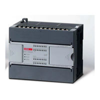
LSIS XGT Series User Manual (1284 pages)
Ultimate Performance XGB Unit
Brand:
LSIS
| Category:
Controller
| Size: 37 MB
Table of Contents
Table of Contents
9
Chapter 1 Introduction
17
Guide to Use this Manual
17
Part1. System
17
Features
19
Terminology
21
Chapter 2 System Configuration
34
Table of Products Configuration
34
Classification and Type of Product Name
36
High Performance Xgb's System Configuration
40
Chapter 3 Specifications
46
Names and Functions of each Part
46
General Specifications
51
Power Specifications
52
Battery
55
Performance Specifications
57
Chapter 4 Installation and Wiring
61
Parameter & Operation Data
61
Attachment/Detachment of Modules
67
Wire
73
Chapter 5 Maintenance
79
Maintenance and Inspection
79
Daily Inspection
80
Periodic Inspection
80
Basic Procedure of Troubleshooting
81
Chapter 6 Troubleshooting
81
Troubleshooting
81
Troubleshooting Questionnaire
87
Troubleshooting Examples
88
Error Code List
92
Chapter 7 EMC Standard
94
Requirements for Conformance to EMC Directive
94
Requirement to Conform to the Low-Voltage Directive
97
Chapter 1 Program Configuration and Operation Method
98
Part2. Basic Functions
98
Programming Basics
98
Operation Mode
120
Memory
123
Chapter 2 CPU Function
127
Type Setting
127
Parameter Setting
128
Self-Diagnosis Function
131
RTC Function
139
Remote Functions
141
I/O Forced On/Off Functions
142
Direct I/O Operation Function
143
Function Saving the Operation History
145
How to Allocate I/O no
146
Program Modification During Operation (Modification During RUN)
147
Read I/O Information
150
Function to Delete All of the PLC
156
Chapter 3 Input/Output Specifications
157
Introduction
157
Main Unit Digital Input Specifications
164
Main Unit Digital Output Specifications
165
Digital Input Specifications
167
Digital Output Specifications
170
Combined Digital I/O Module Input Specification
179
Combined Digital I/O Module Output Specification
180
I/O Modules' Functions
181
Chapter 4 Built-In High-Speed Counter Function
185
High-Speed Counter Specifications
185
Installation and Wiring
205
Internal Memory
206
Example of Using High-Speed Counter
210
Chapter 5 Data Log Function
214
Overview
214
Performance Specifications
219
Specific Functions
221
Regular Save
238
Trigger Save
244
Event Save
265
Additional Functions
287
CSV File Structure
293
SD Memory Card
295
Flag List
301
Data Processing Time
305
Chapter 6 Built-In PID Function
310
Features of Built-In PID Function
310
Basic Theory of PID Control
311
Functional Specifications of PID Control
318
Usage of PID Control Functions
319
PID Instructions
335
PID Auto-Tuning
338
Example Programs
347
Error / Warning Codes
358
Chapter 1 Overview
360
Characteristics
360
Part3. Embedded Positioning
360
Purpose of Positioning Control
362
Signal Flow of Embedded Positioning
363
Function Overview of Embedded Positioning
364
Chapter 2 Specifications
372
External Interface I/O Specifications
374
The Name of each Part
379
Chapter 3 Operation Order and Installation
380
Operation Order
380
Installation
381
Notices in Wiring
382
Chapter 4 Positioning Parameter & Operation Data
400
Parameter & Operation Data
400
Basic Parameter
401
Extended Parameter
406
Manual Operation Parameter
418
Homing Parameter
419
I/O Signal Parameter
423
Common Parameter
424
Operation Data
428
Chapter 5 Internal Memory and I/O Signal
433
Internal Memory
433
I/O Signal
441
Chapter 6 Function Block
444
Common Items of Function Blocks
444
Positioning Module Function Block
446
Function Blocks Related to Reading Module Information
448
Function Blocks Related to Parameters/Changing Operating Data
452
Function Blocks Related to Start-Up and Stop
468
Function Blocks Related to Manual Operation
477
Function Block Related to Synchronous Operation
480
Function Blocks Related to Changes
485
Function Blocks Related Errors
497
Chapter 7 Program
505
Example of Programming
505
Advertisement
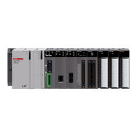
LSIS XGT Series User Manual (1402 pages)
Programmable Logic Controller
Brand:
LSIS
| Category:
Controller
| Size: 35 MB
LSIS XGT Series User Manual (909 pages)
Standalone Motion Controller
Brand:
LSIS
| Category:
Controller
| Size: 25 MB
Table of Contents
Table of Contents
10
Chapter 1 Overview
22
Characteristics
22
Signal Flow of Motion Controller
24
Function Overview of Motion Controller
25
Positioning Control
26
Interpolation Control
26
Speed Control
30
Torque Control
31
Chapter 2 Specification
32
General Specification
32
Power Specification
33
Performance Specification
34
Function Specification
34
Communication Specification
37
Internal Input/Output Specification
38
Encoder Input Specification
40
The Name of each Part
41
Specification of Interface with External Device
42
Chapter 3 Operation Order and Installation
46
Operation Order
46
Installation
47
Safety Precautions
47
Installation Environment
49
Notice in Handling
49
Attachment/Detachment of Motion Controller
50
Notice in Wiring
55
Power Wiring
56
I/O Device Wiring
57
Ground(Lg) Wiring
58
Specifications of Wiring Cable
59
Connection Example of Servo Drive
60
Encoder Input (DC5V Voltage Output) Wiring Example
64
Encoder Input (DC 5V Line Driver Output) Wiring Example
65
External Input Signal Wiring Example
66
External Output Signal Wiring Example
66
Emc
67
EMC Standard
67
Fail Safe
71
Fail Safe Circuit
71
Maintenance
73
Maintenance and Inspection
73
Daily Inspection
73
Periodic Inspection
74
Troubleshooting
75
Basic Procedure of Troubleshooting
75
Troubleshooting Questionnaire
81
Troubleshooting Example
82
Chapter 4 Motion Control Operation
86
Structure of Motion Controller
86
Configuration of Motion Control
87
Motion Control Tasks
88
Types of Tasks
88
Task Operation
89
Execution of Motion Commands
92
Ethercat Communication
93
What Is Ethercat
93
Coe(Canopen over Ethercat)
93
Ethercat State Machine
94
Ethercat Process Data Objective(PDO)
95
Specification of Motion Controller Ethercat Communication
96
Motion Control Program
97
Program Execution
97
Operation Modes
97
Chapter 5 Memory and Parameter
99
Memory
99
Program and Data Memory
99
Device
100
Parameter
106
Chapter 6 Motion Function Block
140
Common Elements of Motion Function Blocks
140
The State of Axis
140
The State of Group
142
Basic I/O Variable
143
Buffermode Input
146
Changes in Parameters During Execution of Motion Function Block
146
Group Operation Route Change Settings
147
Motion Function Block Errors
149
Motion Function Block
150
Single-Axis Motion Function Blocks
153
Servo On/Off (Mc_Power)
153
Perform the Search Home (Mc_Home)
154
Stop Immediately (MC_STOP)
156
Stop (Mc_Halt)
157
Absolute Positioning Operation (Mc_Moveabsolute)
158
Relative Positioning Operation (Mc_Moverelative)
161
Additive Positioning Operation (Mc_Moveadditive)
164
Specified Velocity Operation (Mc_Movevelocity)
168
Absolute Position Operation Ending with Specified Velocity Operation
171
(Mc_Movecontinuousabsolute)
171
Relative Position Operation Ending with Specified Velocity Operation
175
(Mc_Movecontinuousrelative)
175
Torque Control (Mc_Torquecontrol)
178
Setting the Current Position (Mc_Setposition)
180
Velocity/Acceleration Override (Mc_Setoverride)
182
Read Parameter (Mc_Readparameter)
184
Write Parameter (Mc_Writeparameter)
187
Reset Axis Error (Mc_Reset)
190
Touch Probe (Mc_Touchprobe)
191
Abort Trigger Events (Mc_Aborttrigger)
195
Superimposed Operation (Mc_Movesuperimposed)
196
Superimposed Operation Halt (Mc_Haltsuperimposed)
197
Multi-Axis Motion Function Blocks
198
Camming Run (Mc_Camin)
198
Camming Stop (Mc_Camout)
205
Electrical Gearing Run (Mc_Gearin)
208
Electrical Gearing Disengage (Mc_Gearout)
211
Electrical Gearing by Specifying the Position (Mc_Gearinpos)
213
Phase Compensation (Mc_Phasing)
218
Advertisement
LSIS XGT Series User Manual (765 pages)
Positioning Module EtherCAT, Programmable Logic Controller
Brand:
LSIS
| Category:
Controller
| Size: 15 MB
Table of Contents
Table of Contents
10
Chapter 1 Overview
17
Characteristics
17
Function Overview of Positioning Module
20
Interpolation Control
21
Speed Control
26
FEED Control
27
Chapter 2 Specification
28
General Specification
28
Performance Specifications
29
Encoder Input Specifications
31
The Name of each Part
32
Specification of Interface with External Device
33
Chapter 3 Operation Order and Installation
35
Operation Order
35
Installation
36
Notice in Wiring
37
Connection Example of Servo and Stepping Motor Drive Machine
38
Encoder Input (DC 5V Voltage Output) Wiring Example
42
Encoder Input (5V Line Driver Output) Wiring Example
45
Parameter & Operation Data
46
Basic Parameter
47
Chapter 4 Positioning Parameter & Operation Data
48
Basic Parameter Setting
48
Manual Operation Parameter
69
Common Parameter
70
Common Parameter Setting
71
Operation Data
76
Operation Data Setting
77
Chapter 5 Internal Memory and I/O Signal
82
Internal Memory
82
Teaching Data
83
Step Data of Simultaneous Start
84
State Information
85
I/O Signal
92
Use of I/O Signal
93
Chapter 6 Command
95
Contents of General Command
95
Internal Memory Write (PUT, PUTP Command)
96
Dedicated Commands
97
Use of Dedicated Command
99
Homing Start (Command: XORG)
100
Floating Origin Setting (Command: XFLT)
101
Direct Start (Command: XDST)
102
Indirect Start (Command: XIST)
103
Simultaneous Start (Command: XSST)
104
Simultaneous Start Step Setting (Command: XSWR)
106
Speed/Position Switching Control (Command: XVTP)
108
Position Specified Speed/Position Switching Control (Command: XVTPP)
109
Position/Speed Switching Control (Command: XPTV)
110
Position/Torque Switching Control (Command: XPTT)
111
Deceleration Stop (Command: XSTP)
112
Skip Operation (Command: XSKP)
113
Synchronous Start by Position (Command: XSSP)
114
Speed Sync (Command: XSSS)
115
CAM Operation (Command: XCAM)
118
Main Axis Offset-Designated CAM Operation (Command : XCAMO)
119
Position Override (Command: XPOR)
121
Speed Override (Command: XSOR)
122
Position-Specified Speed Override (Command: XPSO)
123
Continuous Operation (Command: XNMV)
124
Inching Operation (Command: XINCH)
125
Start Step No. Change (Command: XSNS)
127
Repeat Step No. Change (Command: XSRS)
128
M Code Release (Command: XMOF)
129
Current Position Preset (Command: XPRS)
130
Encoder Preset (Command: XEPRS)
131
Teaching Array (Command: XTEAA)
132
Set Teaching Array Data (Command: XTWR)
134
Set Basic Parameter (Command: XSBP)
136
Set Extended Parameter (Command: XSEP)
141
Set Common Parameter (Command: XSCP)
149
Set Operation Data (Command: XSMD)
152
Read Variable Data (Command: XVRD)
156
Write Variable Data (Command: XVWR)
158
Emergency Stop (Command: XEMG)
160
Reset Error (Command: XCLR)
161
Reset Error History (Command: XECLR)
162
Point Start (Command: XPST)
163
Read Operation State (Command: XSRD)
166
Servo on (Command: XSVON)
170
Servo off (Command: XSVOFF)
171
Restart (Command: XRSTR)
174
Read Servo Parameter (Command: XSVPRD)
175
Write Servo Parameter (Command: XSVPWR)
178
Control Torque (Command: XTRQ)
180
Read Latch Position Data (Command: XLRD)
181
Reset Latch (Command: XLCLR)
182
Set Latch (Command: XLSET)
183
Torque Synchronous (Command: XSTC)
184
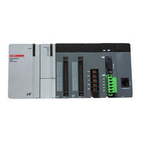
LSIS XGT Series User Manual (384 pages)
XBC Standard/Economic Type Main Unit Programmable Logic Controller
Brand:
LSIS
| Category:
Controller
| Size: 14 MB
Table of Contents
Table of Contents
10
Chapter 1 Introduction
18
Guide to Use this Manual
18
Features
19
Introduction
20
Terminology
21
Chapter 2 System Configuration
23
XGB System Configuration
23
Product List
25
Classification and Type of Product Name
27
Classification and Type of Basic Unit
27
Classification and Type of Expansion Module
29
Classification and Type of Special Module
30
Classification and Type of Communication Module
31
System Configuration
33
Cnet I/F System
33
Ethernet System
36
Chapter 3 General Specifications
37
General Specifications
37
Chapter 4 CPU Specifications
38
Performance Specifications
38
Names of Part and Function
44
Power Supply Specifications
47
Data Backup Time
51
Chapter 5 Program Configuration and Operation Method
52
Program Instruction
52
Program Execution Methods
52
Operation Processing During Momentary Power Failure
53
Scan Time
54
Scan Watchdog Timer
56
Timer Processing
57
Counter Processing
60
Program Execution
62
Configuration of Program
62
Program Execution Methods
62
Interrupt
64
Operation Mode
76
RUN Mode
76
STOP Mode
77
DEBUG Mode
77
Change Operation Mode
81
Memory
82
Data Memory
82
Configuration Diagram of Data Memory
84
S" Type
85
Data Latch Area Setting
86
Chapter 6 CPU Functions
89
Type Setting
89
Parameter Setting
90
Basic Parameter Setting
90
I/O Parameter Setting
91
Self-Diagnosis Function
92
Saving of Error Log
92
Troubleshooting
92
Remote Functions
94
Forced Input/Output on and off Function
95
Force I/O Setup
95
Direct Input/Output Operation
97
Diagnosis of External Device
98
Allocation of Input/Output Number
99
Online Editing
101
Reading Input/Output Information
104
Monitoring
105
Program Upload Prohibit
110
Clear All PLC
111
Password Setting Per Program Block
112
LSIS XGT Series User Manual (374 pages)
Positioning Module for Programmable Logic Controller
Brand:
LSIS
| Category:
Controller
| Size: 5 MB
Table of Contents
Table of Contents
10
Chapter 1 Overview
17
Characteristics
17
Purpose of Positioning Control
19
Signal Flow of Positioning Module
20
Operating Sequence
20
Flow of Position Signal
21
Function Overview of Positioning Module
22
Position Control
22
Interpolation Control
23
Speed Control
26
Chapter 2 Specifications
27
General Specifications
27
Performance Specifications
28
Function Specifications
28
External I/O Interface Specifications
29
Input Specifications
29
Output Specifications
30
Specifications on Interface with External Equipment
31
The Name of each Part
35
Connection to XGT Servo System
36
Chapter 3 Operation Order and Installation
37
Installation
37
Installation Environment
37
Notices in Handling
37
Notices in Wiring
38
Connection Example of Servo and Stepping Motor Drive Machine
39
Encoder Input (DC 5V Voltage Output) Wiring Example
51
Encoder Input (5V Line Driver Output) Wiring Example
52
Chapter 4 Positioning Parameter & Operation Data
53
Parameter & Operation Data
53
Basic Parameter
54
Basic Parameter Setting
55
Home/Manual Parameter
66
Contents of Home/Manual Parameter
66
Home/Manual Parameter Setting
66
Common Parameter
69
Common Parameter Setting
69
I/O Signal Parameter
72
Setting of I/O Signal Parameter
72
Operation Data
73
Operation Data Setting
73
Chapter 5 Program Configuration and Operation Method
78
Internal Memory
78
Teaching Data
78
State Information
80
I/O Signal
85
Contents of I/O Signal
85
Use of I/O Signal
86
LSIS XGT Series User Manual (429 pages)
Motion Control Module
Brand:
LSIS
| Category:
Controller
| Size: 14 MB
Table of Contents
Table of Contents
8
Chapter 1 Overview
12
Characteristics
12
Signal Flow of Positioning Module
14
Function Overview of Motion Control Module
15
Positioning Control
16
Interpolation Control
16
Speed Control
20
Torque Control
21
Chapter 2 Specification
22
General Specification
22
Performance Specifications
23
Function Specifications
23
Communication Specifications
24
Internal Input/Output Specifications
25
Encoder Input Specifications
26
The Name of each Part
27
Specification of Interface with External Device
28
Chapter 3 Operation Order and Installation
31
Operation Order
31
Installation
32
Installation Environment
32
Notice in Handling
32
Notice in Wiring
33
Connection Example of Servo and Stepping Motor Drive Machine
34
Encoder Input (DC 5V Voltage Output) Wiring Example
38
Encoder Input (DC 5V Line Driver Output) Wiring Example
39
Chapter 4 Motion Control Operation
41
Structure of Motion Control Module
41
Configuration of Motion Control
42
Motion Control Task
43
Types of Tasks
43
Execution of Motion Commands
47
Ethercat Communication
48
Coe(Canopen over Ethercat)
48
What Is Ethercat
48
Ethercat State Machine
49
Ethercat Process Data Objective(PDO)
50
Specification of Motion Control Module Ethercat Communication
51
Motion Control Program
52
Program Execution
52
Operation Modes
52
Chapter 5 Memory and Parameter, I/O Signal
54
Memory
54
Flag
54
Device
61
Parameter
68
I/O Signal
95
Contents of I/O Signal
95
Use of I/O Signal
97
LSIS XGT Series User Manual (267 pages)
Programmable Logic Controller, CPU Module
Brand:
LSIS
| Category:
Controller
| Size: 5 MB
Table of Contents
Table of Contents
11
About this User Manual
17
Configuration of the XGR Redundant System
19
Features of the XGR Redundancy System
20
Glossary
22
Chapter 1 Overview
17
Chapter 2 System Configuration
25
Chapter 3 General Specifications
43
Chapter 4 CPU Module
44
Chapter 5 Program Constitution and Operation Method
52
Program Basics
52
Program Structure and Execution
52
Operation of Instantaneous Interrupt
56
Scan Time
57
Performance Specifications
44
Names and Functions of Parts
46
Battery
50
Battery Life
50
Battery Specifications
50
Cautions for Usage
50
Replacement
51
Product List
25
Redundancy System
31
Redundant System Configuration
31
Redundancy of CPU System
35
Extension Base Communication Path Redundancy
36
Extension Drive Redundancy
36
Power Module Redundancy
36
Example of Redundant System Configuration
38
Network System
41
Networking Among Systems
41
Remote I/O System
41
General Specifications
43
Scan Time
59
Program Execution
62
Program Type
62
Restart Mode
63
Task Program
65
Operation Mode
74
RUN Mode
74
Stop Mode
75
Debug Mode
76
Switching Operation Mode
76
Redundancy System Operation
78
Start-Up of Redundant System
80
Memory
82
Program Memory
82
Data Memory
83
Data Retain Area Setting
83
Performance Specifications
109
Identification and Function
110
Type and Specification
112
Parts' Names
113
Selection
114
Examples of Current Consumption/Power Calculations
115
Scan Watchdog Timer
85
Self-Diagnosis Function
85
Battery Level Check
87
I/O Module Check Function
87
Saving Error Log
87
Troubleshooting
87
Clock Function
88
Remote Functions
91
Force I/O Setting
94
Forced On/Off Function of I/O
94
The Point of Time of Method of Forced On/Off Process
95
Error History
96
Mode Change History
96
Operation History Saving Function
96
Shut down History
96
System History
96
External Device Failure Diagnosis Function
97
Operation Mode Setting
98
Data Synchronization Area Setting
100
Setting Operation of Communication
101
Global Status Variable
102
ONE IP Solution
102
Applications and Operations
104
Fault Mask Function
104
Fault Mask Setting
104
Releasing Fault Mask
104
Applications and Operations
105
I/O Module Skip Function
105
Releasing Skip Function
105
Setting and Processing I/O Data
105
I/O Base Skip Function
106
Purpose and Outline of the Operation
106
Releasing Skip Function
106
Setting Method
106
Module Replacement Function During Operation
107
Module Replacement in Redundant System
107
Replacing I/O Module in Redundant System
107
Replacing Base Module in Redundant System
108
LSIS XGT Series User Manual (311 pages)
Programmable Logic Controller XGB Standard/Economic Type Main Unit (IEC)
Brand:
LSIS
| Category:
Controller
| Size: 4 MB
Table of Contents
Table of Contents
10
Chapter 1 Introduction
16
Guide to this Manual
16
Features
17
Terminology
19
Chapter 2 System Configuration
21
XGB System Configuration
21
Product List
22
Classification and Type of Product Name
24
Classification and Type of Basic Unit
24
Classification and Type of Expansion Module
26
Classification and Type of Special Module
27
Classification and Type of Communication Module
28
Classification and Type of Option Module
29
Chapter 3 General Specifications
30
General Specifications
30
Chapter 4 CPU Specifications
31
Performance Specifications
31
Names of Part and Function
36
Power Supply Specifications
38
Data Backup Time
42
Chapter 5 Program Configuration and Operation Method
43
Program Instruction
43
Program Execution Methods
43
Operation Processing During Momentary Power Failure
44
Scan Time
45
Scan Watchdog Timer
47
Program Execution
48
Configuration of Program
48
Program Execution Methods
48
Interrupt
50
Operation Mode
62
RUN Mode
62
STOP Mode
63
DEBUG Mode
63
Change Operation Mode
67
Memory
68
Program Memory
68
Data Memory
69
Data Retain Area Setting
69
Data Memory Map
71
Chapter 6 CPU Functions
73
Type Setting
73
Parameter Setting
74
Basic Parameter Setting
74
I/O Parameter Setting
75
Self-Diagnosis Function
76
Saving of Error Log
76
Troubleshooting
77
Remote Functions
78
Forced Input/Output on and off Function
79
Force I/O Setup
79
Direct Input/Output Operation
81
Diagnosis of External Device
82
Allocation of Input/Output Number
83
Online Editing
85
Reading Input/Output Information
88
Monitoring
89
Clear All PLC
94
LSIS XGT Series User Manual (236 pages)
Brand:
LSIS
| Category:
Controller
| Size: 6 MB
Table of Contents
Table of Contents
12
Chapter 1 Introduction
18
Guide to Use this Manual
18
Features
19
Terminology
21
Chapter 2 System Configuration
24
XGB System Configuration
24
Product List
25
Classification and Type of Product Name
27
Classification and Type of Main Unit
27
Classification and Type of Expansion Module
28
Classification and Type of Special Module
29
Classification and Type of Communication Module
30
Classification and Type of Option Module
30
System Configuration
31
Cnet I/F System
31
Ethernet System
34
Chapter 3 General Specifications
36
General Specifications
36
Chapter 4 CPU Specifications
38
Performance Specifications
38
Names of Part and Function
40
Power Supply Specifications
41
Calculation Example of Consumption Current/Voltage
43
Battery
45
Battery Specification
45
Notice in Using
45
Life of Battery
45
How to Change the Battery
46
Chapter 5 Program Configuration and Operation Method
48
Program Instruction
48
Program Execution Methods
48
Operation Processing During Momentary Power Failure
49
Scan Time
50
Scan Watchdog Timer
51
Program Execution
52
Configuration of Program
52
Program Execution Methods
52
Interrupt
54
Operation Mode
66
RUN Mode
66
STOP Mode
67
DEBUG Mode
67
Change Operation Mode
71
Memory
72
Program Memory
72
Data Memory
73
Data Retain Area Setting
73
Data Memory Map
75
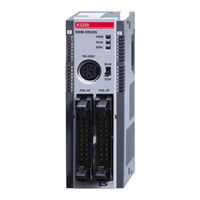
LSIS XGT Series User Manual (278 pages)
Programmable Logic Controller Dnet I/F Module
Brand:
LSIS
| Category:
Control Unit
| Size: 10 MB
Table of Contents
Table of Contents
9
Chapter 1 Introduction
12
What Is Devicenet
12
Characteristics of the Module
13
Information for Module Operation
14
Configuration of Smart I/O for Dnet
15
Chapter 2 Specifications
17
General Specifications
17
Performance Specifications
18
Part Names and Structure
20
Cable Specifications
21
Terminating Resistor
22
Tap/Divider
23
Chapter 3 Installation and Test Operation
25
Installation
26
From Setting to Operation
31
Setting Procedure of N Configurator and XG5000
32
Chapter 4 System Configuration
33
System with LS Dnet I/F Module Used
33
System with Multi-Master Used
35
Chapter 5 N Configurator Setting
36
EDS Analyzer
36
Project File Management
39
Binary File Management
42
Excel Report
45
Program Exit
52
N Configurator Overview
53
N Configurator Features
54
System Requirements for Running N Configurator
56
N Configurator Installation
57
Editing Devices
61
Changing Display Method
65
Screen Configuration
72
Fast Start
83
Device List
88
EDS Viewer
89
Project Explorer
91
Master Property Window
93
Bus Parameter Window
94
Slave Property Window
95
Output Window
96
Shrink Topology
97
Toolbar/Status Bar
99
Project Property Settings
100
Master Properties
102
Bus Parameter
105
Slave Properties
106
Slave I/O Modules
112
Slave Parameters
120
Communication Settings
127
Download Binary Images
129
Download Binary Files
131
Master Slave Control
135
Slave Device Monitoring
137
Device Diagnostics
148
Network Scan
152
Device Table
156
Device Communication Type Table
159
Slave I/O Address Table
161
Option Window
168
Window Management
175
Project Window Management
183
Project Tab Group Management
185
LSIS XGT Series User Manual (194 pages)
Programmable Logic Controller, Main Unit, Built-in Cnet, XGB Cnet I/F, Module
Brand:
LSIS
| Category:
Controller
| Size: 4 MB
Table of Contents
Table of Contents
9
Chapter 1 General
14
General
14
Characteristic
15
Chapter 2 Specification
16
General Specification
16
Performance Specification
18
Name and Function of each Part
20
Chapter 3 System Configuration
25
XGB System Configuration
25
H" Type System Configuration
25
S" Type System Configuration
26
Available System Configuration
27
1:1 Connection between PC (HMI) (no Modem)
27
1:1 Dedicated Modem Connection with PC (HMI)
30
Modem Connection with PC and Communication between Cnet I/F Modules
31
Dedicated Communication with PC (HMI) and Different Type RS-422 Communication
32
Optical Modem Communication for Moving Material Communication
33
Wireless Modem Communication for Communication between Revolution Bodies
34
Chapter 4 Basic Setting
35
Setting Sequence of Product
35
PLC Type Setting and How to Register Communication Module
36
Making New Project
36
In Case of off Line, Method on Cnet I/F Module Registration
36
How to Register Cnet I/F Module in Case of Online
37
How to Set Basic Parameter
39
Setting Item
40
Setting Method
41
Chapter 5 Remote Connection
43
General
43
XG5000 Remote Connection
43
Remote Connection between Cnet I/F Modules
50
Chapter 6 Server Function and P2P Service
55
Server Modbus Service
55
General
55
XGT Dedicated Server
56
Modbus Server
56
P2P Service
58
General
58
P2P Parameter Configuration
59
Channel Information
59
Block Information
61
User Defined Frame Information
65
P2P Service Operation
75
Chapter 7 XGT Dedicated Protocol
77
XGT Dedicated Protocol
77
General
77
Frame Structure
78
List of Commands
79
Data Type
80
Detail of Instruction
82
LSIS XGT Series User Manual (191 pages)
Pnet I/F Module
Brand:
LSIS
| Category:
Control Unit
| Size: 10 MB
Table of Contents
Table of Contents
10
Chapter 1 Introduction
15
Chapter 7 N Configurator Setting
15
Introduction
15
Characteristics
15
Product Configuration
16
Model Name
16
Available Number by CPU
16
Slave Device
17
Software
18
Check List for the Software
18
Xg5000
19
Checking the Version
19
Chapter 2 Specifications
21
General Specifications
21
Performance Specifications
22
Structure & Characteristics
23
Structure of Pnet I/F Module
23
Cable Specifications
26
Chapter 3 Installation and Test Operation
27
Precautions for Installation
27
From Setting to Operation
28
Installation of XGL-PMEA
29
Test Operation
32
Precautions for System Configuration
32
Chapter 4 System Configuration
33
System Configuration of Network
33
XGT Pnet + Smart I/O
33
XGT Pnet + Composite System
34
Chapter 5 Communication Program
35
Communication Program
35
Type of Communication Program
35
Xg5000
36
Setting PLC Type
36
Registration of the Communication Module
38
Uploading High Speed Link Parameter and Setup
42
Chapter 6 Sycon Setting
50
Introduction
50
Main Functions
50
Characteristics
50
Installation
50
System Requirements
50
Software Installation
51
Communication Settings in Sycon
57
Initial Screen
57
Composition of Menu
58
New File
60
Master Selection
60
Slave Selection
64
Bus Parameter
66
Online Function
67
Introduction
67
Online to the CIF
67
Automatic Network Scan
67
Start/Stop Communication
69
Debug Mode
69
Diagnostic Functions
69
Installation
72
System Requirements
72
Screen Composition
73
Menu Composition
74
New Project(New File)
80
Master Composition
81
Slave Composition
83
Bus Parameter
86
Download and Upload Network Configuration
87
Download Network Settings
87
Upload Network Settings
89
Diagnosis Function
90
Start / Stop Communication
90
Debug Mode (Start/Stop Debug Mode, Device Diagnostics)
90
Live List
92
Automatic Network Scan
93
I/O Data Monitoring
94
Disconnection Report
95
Master Information (Device Information)
95
Master Reset (Firmware Reset)
95
LSIS XGT Series User Manual (287 pages)
Programmable Logic Controller, Cnet I/F Module
Brand:
LSIS
| Category:
Controller
| Size: 8 MB
Table of Contents
Initial Status
196
Module Setting Error
196
Channel Setting Error
196
DTR Level Setting Error
205
Communication Parameter Setting Error
205
Version Compatibility Error
205
LSIS XGT Series User Manual (164 pages)
Programmable Logic Controller, RAPIEnet I/F Module
Brand:
LSIS
| Category:
Control Unit
| Size: 4 MB
Table of Contents
Table of Contents
10
Chapter 1 Introduction
13
Introduction
13
Features
14
Product Configuration
15
Type
15
Number of Modules Available by CPU Types
15
Software for Product
16
Check Point for Software
16
Xg-Pd
16
Version Information
17
Chapter 2 Product Specifications
18
General Specifications
18
Performance Specifications
20
Expectation of Communication Load
22
Structure and Characteristics
24
Cable Specifications
26
Optical Cable
28
Chapter 3 Installation and Test Operation
29
Installation Environment
29
Precaution for Handling
34
Sequence from Installation to Operation
35
Rapienet I/F Module for PLC
35
Rapienet I/F Module for PC
36
Parameter Setting in the XG-PD
37
Parameter Setting
37
I/O Allocation and Device Information
38
I/O Allocation
38
Installation
43
Installation of XGL-EIMT and XOL-EIMT
43
Installation of XGL-EIMF and XOL-EIMF
45
Installation of XGL-EIMH
46
Test Operation
47
Precautions for System Configuration
47
Chapter 4 System Configuration
48
Available System Configuration
48
Ring Type System with Electric Module
48
Ring Type System with Optical Module
50
Ring Type System with Combined Module
51
Line Type System with Optical Module
52
Chapter 5 Communication Parameters
53
Introduction
53
High-Speed Link Setting Parameters
53
P2P Setting Parameters
54
Comparison between High Speed Link and P2P
55
Installation and Execution of Software
56
Installation of XG5000
56
Installation of USB Device Driver
59
Confirmation of Installed USB Device Drive
63
Registration of Communication Module
70
Off-Line Registration
70
On-Line Registration
71
How to Read the Parameter Saved in the PLC
72
Module Setting Method
73
Menu Bar and Shortcut of XG-PD
74
How to Set the Parameter According to Service
75
High-Speed Link Service
75
P2P Service
78
Operation Start-Up
79
XG-PD Setting
79
When Operating in High Speed Link Service
80
Operating in P2P Service
86
LSIS XGT Series User Manual (151 pages)
Programmable Logic Controller
Brand:
LSIS
| Category:
Temperature Controller
| Size: 3 MB
Table of Contents
Safety Instructions
3
Revision History
8
Table of Contents
10
Chap. 1 Introduction
13
Chapter 1 Introduction
13
Features
13
Terms
14
Chapter 2 Specifications
15
General Specifications
15
Performance Specifications
16
Names and Functions of Major Components
17
Characteristics of Input and Output Conversion
18
Characteristics of Input Conversion
18
Precision by Input Type
18
Characteristics of Output Part Conversion
19
Main Functions
20
Chapter 3 Installation and Wiring
21
Installation
21
Conditions for Installation
21
Cautions in Handling the Module
21
Wiring
22
Wring of the Input Part
22
Wiring of the Output Part
24
Chapter 4 Configuration and Functions of Internal Memory (XGK)
25
U Device Area
25
Parameter Setting Area (Using PUT/GET Command)
29
Parameter Setting Area
29
How to Use PUT/GET Command
32
Chapter 5 Configuration and Functions of Internal Memory (XGI/XGR)
36
Global Variables (Data Area)
36
How to Use Global Variables
38
PUT/GET Function Block Area (Parameter Area)
45
PUT/GET Function Block
47
Example of Use of PUT/GET Function Block
49
Chapter 6 Function
51
Input Parameter
51
Type of Input
51
Input Processing
54
Control Parameter
57
Configuration of the Control Target
57
Address the Control Target
59
Control Type
61
Control Processing Technique
65
Auto Tuning
72
Output Parameter
74
Output Settings
74
Heating Output
75
Cooling Output
81
Other Functions
85
Alarm Function
85
LSIS XGT Series User Manual (123 pages)
Ethernet/IP I/F Module
Brand:
LSIS
| Category:
Control Unit
| Size: 4 MB
Table of Contents
Table of Contents
10
Chapter 1 Overview
12
Overview
12
Features
13
Product Components
14
Indication of Type Names
14
The Number of Installation Available - Units by Cpus
14
Software for Using Products
15
Confirms for Software
15
Xg5000
15
Confirmation of Versions
16
Chapter 2 Specification
17
General Specification
17
Performance Specification
18
Name in each Part
19
Cable Standards
21
UTP Cable
21
Chapter 3 Installation and Test Operation
24
Installation Environment
24
Cautions When Handling
25
The Order for Setting up Products Till Running
26
I/O Allotment and Device Information
27
I/O Allotment
27
Available Device Area Per CPU Series
33
Installation of Products
34
Installation of XGL-EIPT
34
Test Operation
36
Directions When Configuring Systems
36
Chapter 4 System Configuration
37
Configuration of a Usable System
37
System Configuration Using a Switch
37
System Configuration Not Using a Switch
37
Configuration of an Unusable System
38
System Configuration Using a Switch
38
Configuration of a Ring System (Configuration of a XGL-EIPT Ring)
38
Chapter 5 Installation of Software and Communication Parameters
39
Installation and Execution of Software
39
Installation of XG5000
39
Installation of USB Device Drive
42
Confirmation on the Installation of USB Device Driver
45
How to Register Communication Modules
53
In Case of Offline
53
In Case of Online
55
In Case of Reading Parameter Stored in PLC
57
How to Set-Up Modules
58
Menu Bar and Shortcut of XG5000
60
Chapter 6 EIP Service
62
Ethernet/Ip Communication Method
62
Ethernet/Ip Terms
62
EDS File
62
Periodic Communication (Implicit) System
63
Aperiodic Communication (Explicit) System
64
EIP Service
65
Tag Setup
66
Setup of Periodic/Non-Periodic Communication Service
69
Periodic Client Communication Service
69
Setup of Non-Periodic Client Communication Service
76
Periodic Server Communication Service
78
XG5000 Set-Up
80
Communication with Rockwell 1756-ENBT Communication Module
82
LSIS XGT Series User Manual (116 pages)
Programmable Logic Controller XGB Load Cell Input Module
Brand:
LSIS
| Category:
I/O Systems
| Size: 4 MB
Table of Contents
Table of Contents
10
Chapter 1 Overview
12
Features
12
Definition of Terms
13
Chapter2 Specifications
14
General Specifications
14
Performance Specifications
16
Performance Specifications of XBF-LD02S Module
16
Part Names and Structure
17
Part Names and Structure of XBF-LD02S Module
17
Input Conversion Characteristics
18
Input Area Conversion Characteristics
18
Accuracy
19
Functions
21
Chapter 3 Installation and Wiring
22
Installation Environment and Suggestions
22
Wiring
22
Wiring
23
Input Area Wiring
23
Chapter 4 Memory Structure(XBC)
26
U Device Area
26
Parameter Setting Area(PUT/GET Commands Used)
30
Parameter Seting Area
30
Methods on How to Use PUT/GET Commands
40
Chapter 5 Memory Structure(XEC)
44
Global Variables(Data Area)
44
Methods on How to Use Global Variables
47
PUT/GET Function Blocks
49
Chapter 6 Functions
51
Functions
51
Calibration Function
51
Stable Status Determination
58
Zero Tracking Function
59
Zero Setting, Reset
60
Maximum / Minimum Value Output Function
61
Output Value Maintenance Function
62
Alarm Output Function
63
Average Processing Function
65
Free Fall Compensation Function
68
Special Module Monitor Function
81
Chapter 7 Programming(XBC)
85
Setting Procedures before Running
85
Program Example
86
Calibration Setting
86
Automatic Registration of U Device (Module Variable)
90
Weight Measurement Example
93
Using PUT/GET Command
96
Chapter 8 Programming(XEC)
97
Setting Procedures before Running
97
Program Example
98
Calibration Setting
98
Automatic Registration of U Device(Module Variable)
102
Weight Measurement Example
106
Using PUT/GET Command
109
LSIS XGT Series User Manual (99 pages)
XGT Panel Series
Brand:
LSIS
| Category:
Touch Panel
| Size: 4 MB
Table of Contents
Installation Precautions
3
Table of Contents
7
Chapter. 1 General Introduction
10
Usage of User Manual
10
Feature
11
Terminology
15
Chapter. 2 System Configuration
16
Name and Function of each Part
16
System Configuration
20
Chapter. 3 Standard Specification
22
General Standards
22
Function Standards
24
Chapter. 4 System Configuration
30
Touch Calibration
31
Backlight Setting
32
Date Time Setting
33
PC Connection Setting
34
Ethernet Setting
35
Contrast Setting (Only for XP30-BTA/DC)
36
Environment Setting
37
Chapter. 5 Diagnostics
38
Screen Diagnosis
38
Touch Diagnosis
39
Backup Memory Diagnosis
39
Flash Memory Diagnosis Function
40
CF Card Diagnosis
40
Serial Communication Diagnosis
41
LED Diagnosis
43
Aux Diagnosis
43
Chapter 6 Viewing Information of PLC Connection Status
44
Connection Information
45
PLC Information
46
History of PLC Error
47
History of PLC Mode Conversion
48
History of PLC Power
49
History of PLC System
50
PLC Communication Configuration Settings
51
Chapter 7 Storage Function
52
General Introduction
52
Downloading Project through the Storage Equipment
53
Uploading Project through the Storage Equipment
53
Updating the Device through Storage Equipment
54
Chapter 8 XGT Panel S/W Update
55
General Introduction
55
Chapter 9 File Backup through External Storage Equipment
56
Path Structure in Case of File Backup
56
Operation Setting When There Is No Space for Backup
58
Monitoring Connection Status of External Storage Equipment
59
Chapter 10 Installation and Wiring
61
Installation
61
LSIS XGT Series User Manual (90 pages)
Programmable Logic Controller,Sequence of Events Input Module
Brand:
LSIS
| Category:
I/O Systems
| Size: 4 MB
Table of Contents
Table of Contents
7
Chapter 1 Introduction
10
How to Use the Manual
10
Introduction of the Module
11
Names and Functions of each Part
12
Features of the Module
13
How to Install the Module
14
Separation of the Module
16
Differences with DC Input Module
17
Glossary
18
Chapter 2 Specifications
19
General Specifications
19
Performance Specifications
20
Circuit System of the Terminal Block
21
Key Functions
22
Setting the Soe's Functions and Operations
22
Display Functions and Diagnosis
22
External Time Format(IRIG-B)
23
Signal Process
26
Chapter 3 Installation and Wiring
27
Installation
27
Installation Environment
27
Precautions on Handling
27
Wiring
28
Precautions on Wiring
28
Wiring of DC 24V
29
Specifications for Power Supply
29
Using the External Time Information
30
In Case of Using the External Time
30
Chapter 4 Operation Setting and Monitor
31
Operation Setting and Monitor
31
Setting the Basic Parameters
32
Setting Items
32
How to Set the Basic Parameters
32
Setting I/O Parameters
34
How to Use I/O Parameters
34
I/O Parameters Setting Screen
34
SOE Operations Setting Screen
36
Monitoring and Event History Display
41
Monitoring Screen
41
SOE Monitor Screen
43
Save as Excel File
52
Automatic Registration of U Device
54
Chapter 5 Function Setting
57
SOE Functions
57
Setting Event History
58
Setting Items
58
Setting Event Conditions
60
Setting Items
60
Setting Input Filter
61
Setting Items
61
Example of Setting the Input Filter
62
Setting Chattering Detection
63
Setting Items
63
Setting External Time
65
Setting Items
65
LSIS XGT Series User Manual (96 pages)
BACnet/IP I/F Module
Brand:
LSIS
| Category:
Control Unit
| Size: 3 MB
Table of Contents
Table of Contents
10
Chapter 1 Overview
12
Overview
12
Features
13
Product Configuration
14
Module Name Indication
14
Number of Units Installed by CPU
14
Software to Use the Product
15
Software Check Point
15
Xg5000
15
Check of Version
16
Chapter 2 Product Specifications
17
General Specifications
17
Performance Specifications
18
Designations of Parts
19
Cable Specifications
21
Chapter 3 Installation and Test Operation
24
Installation Environment
24
Precautions for Handling
25
Operation Sequence
26
I/O Assignment and Device Information
27
I/O Assignment
27
Installation of the Product
32
Precaution
34
Chapter 4 System Configuration
35
Available System Configuration
35
Chapter5 Communication Parameter
36
Overview
36
XGL-BIPT Profile
36
Communication Service
36
ID Allocation of Input / Output Modules
37
Input / Output Modules Possible to Support
37
Object ID Allocation Method of Input / Output Modules
38
Object ID Mapping of Input/ Output Modules
38
Installation and Execution of Software
41
XG5000 Installation
41
USB Device Driver Installation(Installation in Windows XP)
44
Confirmation of Installed USB Device Driver
47
Communication Module Registration
53
Off-Line Registration of Bacnet I/F Module
53
Online Registration of Bacnet I/F Module
55
How to Read the Parameter Saved in the PLC
57
Menu Bar and Shortcut of XG5000
59
Chapter 6 P2P Service
61
Overview
61
Service Settings
62
Module Settings
62
Start of the Operation
66
XG5000 Settings
66
Status Information by Service
68
System Diagnosis to P2P Service
68
LSIS XGT Series User Manual (67 pages)
Programmable Logic Controller XGK/I/R Datalog Module
Brand:
LSIS
| Category:
Controller
| Size: 3 MB
Table of Contents
Table of Contents
9
Chapter 1 Introduction
12
Special Feature
12
Introduction of Data Processing
14
Chapter 2 Product Specification
15
General Specifications
15
Performance Specifications
16
System Configuration
17
Application System
17
Part Name
18
Contents of LED Display
19
Chapter 3 Installation and Test Operation
20
Installation Environment
20
Precautions for Handling
21
Chapter 4 Setting Sequence
22
Sequence of Setting the Datalog Module
22
Method to Set Datalog Module
23
Chapter 5 Input/Output Signal of Datalog Module
33
Input/Output Signal of Datalog Module
33
Description of Input/Output Signals
35
File Configuration
36
CSV File Format
36
Format Specification of CSV File
36
Data Saving File
37
Chapter 6 Data Saving Function
39
Saving Data
40
Data Saving
41
Data Saving Method
41
Scan Time Data Saving
41
Data Saving at a Task Interval
42
Saving Method
42
Saving Designated by the Ladder Program
42
Data Saving File
43
Saving Type of Data Saving File
43
Saving Method of Data Saving File
43
Saving CF Card Initialized File
43
Chapter 7 CF Card
44
CF Card
44
Name of CF Card Part
44
Cautions in Using CF Card
45
CF Card /Folder Name
45
When Disconnecting or Replacing CF Card
45
CF Card Capacity
45
Manipulation in Mounting CF Card
45
Manipulation in Disconnect or Replace CF Card
46
Lifetime of CF Card
47
Calculation of Lifetime
47
Total Writable Size
47
Processing Time
47
LSIS XGT Series User Manual (69 pages)
Programmable Logic Controller, XGB Rnet Master I/F Module
Brand:
LSIS
| Category:
Control Unit
| Size: 3 MB
Table of Contents
Table of Contents
10
Chapter 1 Introduction
12
What Is Rnet
12
What I Rnet?
12
Characteristics of the Module
13
Information for Module Operation
14
Configuration of for Rnet
15
Chapter 2 Specifications
16
General Specifications
16
Performance Specifications
17
Part Names and Structure
20
Cable Specifications
21
Chapter 3 Installation and Test Operation
23
Installation
23
Precautions for Installation
23
Materials Necessary for Installation
23
From Setting to Operation
24
Chapter 4 System Configuration
25
System with Rnet I/F Module Used
25
Mixed Configuration 1 between XBL-RMEA + Repeater + Rnet Slave
25
Mixed Configuration 2 between XBL-RMEA + Repeater + Rnet Slave
26
Chapter 5 High-Speed Link Setting
27
Introduction
27
How to Use XG5000
28
High-Speed Link Editing
29
Read and Write of High-Speed Link
35
Enable Link
37
System Diagnosis
38
Chapter 6 Communication Program
44
Example Program
44
Chapter 7 Troubleshooting
49
Symptoms and Management by LED Status
49
System Diagnosis in XG5000
50
Communication Module Information
50
High-Speed Link
50
Diagnosis of Communication Module through XG5000
52
Trouble Shooting for Respective Error
53
XG5000 Abnormal Connection
53
Communication Error with Master Module
54
Appendix
55
List of Flags
55
Special Register for Data Link
55
Special Relays
57
Terminology
65
External Dimensions
67
LSIS XGT Series User Manual (61 pages)
Programmable Logic Controller Fnet I/F Module
Brand:
LSIS
| Category:
Controller
| Size: 2 MB
Table of Contents
Table of Contents
10
Chapter 1 Overview
12
Overview
12
Characteristics of XGT Fnet I/F Module and Difference from GM/MK Fnet
13
Characteristics of XGT Fnet I/F Module
13
Difference from GM/MK Fnet
13
Product Information
14
Models
14
Maximum Number of Mounting Per CPU
14
Chapter 2 Product Specification
15
General Specifications
15
Performance Specifications
16
Structure and Features
17
Cable Specification
18
Electric Cable (LS Cable)
18
Cable Joint Method
18
Terminating Resistor
19
Chapter 3 Product Installation and Test-Run
20
Cautions for Handling
20
Product Setting for Operation
21
Registration of Communication Module
22
Off-Line Registration
22
Online Registration
23
Reading Parameters from PLC
25
Module Setting Procedure
27
Relation between the Menu Bar and Shortcut Icons of XG-PD
28
Chapter 4 System Configuration
30
Network System Configuration
30
Chapter 5 High Speed Link Service
32
Outline of High Speed Link
32
Using XG-PD
33
Setting-Up High Speed Link
38
Read and Write High Speed Link
43
System Diagnosis
44
High Speed Link (HSL) Information
47
Chapter 6 Sample Program
48
Application Sample in XGK-CPU
48
Example Using XGI-CPU
50
Chapter 7 Max. Guarantee Time for Data Communication
52
Maximum Guarantee Time for Communication between Stations
52
Calculation of the Max. Guarantee Time for Data Communication between Stations
53
Master Switching Time
54
Appendix
55
Appendix 1 Terms and Definitions
55
Appendix 3 Dimensions
59
LSIS XGT Series User Manual (43 pages)
Human Machine Interface
Brand:
LSIS
| Category:
Recording Equipment
| Size: 5 MB
Table of Contents
Table of Contents
8
Chapter 1 Introduction
10
Introduction
10
Special Feature
10
Product Configuration
10
Model Name Marking
10
The Number of Mountable System
10
Software for Using the Product
11
XP-Builder
11
Checking the Version of Profibus-DP I/F Module
11
Chapter 2 Product Specification
12
General
12
Performance Specification
13
Installable XGT Panel
13
Part Name
14
Communication Cable Specification
15
Profibus-DP Cable Specification
15
Chapter 3 Installation and Trial Run
17
Installation Environment
17
Cautionary Notes
18
Setting Sequence
19
Parameter Setting in XP-Builder
20
Connection of Product
20
Profibus-DP I/F Module Connection
20
Example of Connecting between Stations
20
Trial Run
21
Caution in Configuring the System
21
Chapter 4 System Configuration
22
Various Ways of System Configuration
22
System that Consists of One Master and Several Xps
22
System that Consists of One Master, Several Xps and Other Various Slaves
22
Chapter 5 Profibus-DP Communication
23
Introduction
23
Sending/Receiving Processing of Profibus-DP Communication
24
Sequence to Operate Profibus-DP Communication
25
Profibus-DP Communication Setting
26
Setting Profibus-DP on XP-Builder
26
Chapter 6 Setting Example
30
Profibus-DP Communication
30
Example System
30
Setting Slave (XP) Parameter
31
Setting Master Configuration (in Case of Sycon)
32
XP-Builder Device Settings
34
Editing Object
34
Chapter 7 Diagnosis Function
36
Diagnosis Information
36
Profibus-DP Diagnosis Information Area
36
LED Information
37
Troubleshooting
38
Appendix
40
Terminology
40
Dimension
41
LSIS XGT Series User Manual (51 pages)
Rnet I/F Module
Brand:
LSIS
| Category:
Control Unit
| Size: 1 MB
Table of Contents
Table of Contents
10
Chapter 1 Overview
12
Introduction
12
Characteristics
13
Product Information
14
Components List
14
Max. Installation Number of Modules
14
Chapter 2 Specifications
15
General Specifications
15
Performance Specifications
16
Structure and Characteristics
17
Terminal Resistance
20
Chapter 3 Installation and Test Operation of the Product
21
Precautions for Installation
21
From Setting to Operation
21
Chapter 4 System Configuration
22
System Configuration of Network
22
XGL-RMEA/B + Smart I/O
22
Mixed Configuration between XGL-RMEA/B and Various Slave Modules
22
Chapter 5 High-Speed Link Setting
23
Introduction
23
How to Use XG5000
24
High-Speed Link Editing
30
Read and Write of High-Speed Link
35
System Diagnosis
36
High-Speed Link Information
41
Chapter 6 Program Example
43
XG5000 Program
43
Appendix
46
Terminology
46
List of HS Link Flags
47
External Dimensions
49
LSIS XGT Series Manual (48 pages)
Programmable Logic Controller Diagnostic Digital I/O Module
Brand:
LSIS
| Category:
Control Unit
| Size: 1 MB
Table of Contents
Table of Contents
10
Features of Diagnostic Digital Input / Output Module
12
Diagnostic Digital Input Module
12
Diagnostic Digital Output Module
13
Cautions for Selecting Module
14
Chapter 2 Specifications and Functions
17
General Specifications
17
Performance Specifications
18
Performance Specifications of Diagnostic Digital Input Module (XGI-D21D)
18
Performance Specifications of Diagnostic Digital Output Module (XGQ-RY1D)
19
Names and Functions of Parts
20
Names and Functions of Parts of Diagnostic Digital Input Module (XGI-D21D)
20
Names and Functions of Parts of Diagnostic Digital Output Module (XGQ-RY1D)
21
Functions of Diagnostic Digital I/O Module
22
Functions of Diagnostic Digital Input Module
22
Functions of Diagnostic Digital Input Module
26
Chapter 3 Installation and Wiring
32
Installation
32
Installation Environment
32
Cautions for Handling
33
Attachment/Detachment of Modules
36
Wiring
38
I/O Device Wiring
38
Specifications of Wiring Cable
38
Wiring for Diagnostic Digital Input Module (XGI-D21D)
39
Wiring for Diagnostic Digital Output Module (XGQ-RY1D)
40
Chapter 4 Troubleshooting
41
Basic Troubleshooting Procedure
41
Troubleshooting
42
Cases
44
Trouble Types and Measures of Input Circuit
44
Trouble Types and Measures of Output Circuit
45
Appendix 1 Dimensions
46
Advertisement
Related Products
LSIS XGL-EFMF
LSIS XGL-EH5T
LSIS XGL-EFMFB
LSIS XGL-CH2A
LSIS XGR-DBSF
LSIS XGR-DBSFS
LSIS XGL-FMEA
LSIS XGB Series
LSIS XGL-CH2B
LSIS XGL-C42A
LSIS Categories
Controller
Inverter
Control Unit
DC Drives
Relays
More LSIS Manuals
Login
Sign In
OR
Sign in with Facebook
Sign in with Google
Upload manual
Upload from disk
Upload from URL