LSIS XGT Series User Manual
Programmable logic controller, cpu module
Hide thumbs
Also See for XGT Series:
- User manual (909 pages) ,
- Manual (48 pages) ,
- User manual (61 pages)
Table of Contents
Advertisement
Quick Links
Right choice for ultimate yield
LSIS strives to maximize customers' profit in gratitude of choosing us for your partner.
Programmable Logic Controller
XGT Series
Read this manual carefully before
installing, wiring, operating, servicing or
inspecting this equipment.
Keep this manual within easy reach for
quick reference.
XGR CPU Module
Expansion drive
User's Manual
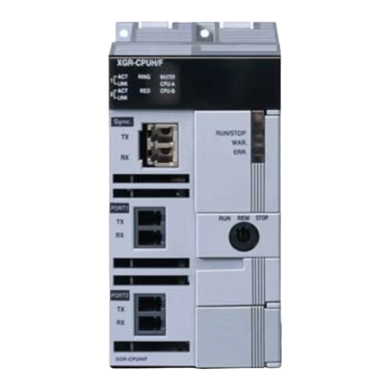
XGR-CPUH/F
CPU
XGR-CPUH/T
XGR-CPUH/S
XGR-DBST
XGR-DBSF(S)
XGR-DBSH(S)
XGR-DBDT
XGR-DBDF
XGR-DBDH
http://www.lsis.com
Advertisement
Table of Contents
Troubleshooting

Related Manuals for LSIS XGT Series


Summary of Contents for LSIS XGT Series
- Page 1 Right choice for ultimate yield LSIS strives to maximize customers' profit in gratitude of choosing us for your partner. Programmable Logic Controller XGR CPU Module XGT Series User’s Manual XGR-CPUH/F XGR-CPUH/T XGR-CPUH/S XGR-DBST Expansion drive XGR-DBSF(S) XGR-DBSH(S) XGR-DBDT XGR-DBDF XGR-DBDH Read this manual carefully before ...
- Page 2 Safety Instructions Before using the product … For your safety and effective operation, please read the safety instructions thoroughly before using the product. ► Safety Instructions should always be observed in order to prevent accident or risk with the safe and proper use the product. ►...
- Page 3 Safety Instructions Safety Instructions when designing Warning Please, install protection circuit on the exterior of PLC to protect the whole control system from any error in external power or PLC module. Any abnormal output or operation may cause serious problem in safety of the whole system.
- Page 4 Safety Instructions Safety Instructions when designing Caution I/O signal or communication line shall be wired at least 100mm away from a high-voltage cable or power line. If not, it may cause abnormal output or operation. Safety Instructions when designing Caution ...
- Page 5 Safety Instructions Safety Instructions when wiring Warning Prior to wiring, be sure that power of PLC and external power is turned off. If not, electric shock or damage on the product may be caused. Before PLC system is powered on, be sure that all the covers of ...
- Page 6 Safety Instructions Safety Instructions for test-operation or repair Warning Don’t touch the terminal when powered. Electric shock or abnormal operation may occur. Prior to cleaning or tightening the terminal screws, let all the external power off including PLC power. If not, electric shock or abnormal operation may occur.
- Page 7 Revision History Revision History Version Data Main contents Revised location V 1.0 ’08. 6 First Edition 1. Modifying contents V 1.1 ’08.7 (2) How to configure redundancy system 4-1,4-2 (3) Performance specification (4) Scan Time 5-6,5-8 (5) Program memory 5-28 (6) I/O module skip function 6-19,6-20 (7) Module changing wizard during RUN...
- Page 8 Revision History Version Data Main contents Revised location 1. Adding contents Ch8.1, Ch8.2, Ch8.3 V 1.4 ’09.12 (1) adding contents related to DC power 1. Adding contents V 1.5 ’10.03 (1) Contents on reset/D.Clear (2) Contents on Cnet/FEnet module equipment (3) Contents on redundancy parameter 5-8~9 (4) Warning flag...
- Page 9 (5) CPU Processing Speed Unit changed (us ns) (6) List of Configuration Products updated 1.Modifying contents V 2.4 ‘16.03 (1) Smart Link manual supplemented ※ The number of User’ s manual is indicated right part of the back cover. ⓒ LSIS Co., Ltd 2008 All Rights Reserved.
- Page 10 User’s Manual. The User’s Manual describes the product. If necessary, you may refer to the following description and order accordingly. In addition, you may connect our website(http://eng.lsis.biz/) and download the information as a PDF file. Relevant User’s Manuals No.
-
Page 11: Table Of Contents
TABLE OF CONTENTS ◎ TABLE OF CONTENTS ◎ Chapter 1 Overview ......................... 1-1~1-8 1.1 About this User Manual ........................1-1 1.2 Configuration of the XGR Redundant System .................. 1-3 1.3 Features of the XGR Redundancy system ..................1-4 1.4 Glossary ............................1-6 Chapter 2 System Configuration.................... - Page 12 TABLE OF CONTENTS 5.2.1 Program Type ..........................5-11 5.2.2 Program Execution ........................5-11 5.2.3 Restart Mode ......................... 5-12 5.2.4 Task Program ........................5-14 5.3 Operation Mode..........................5-23 5.3.1 Operation Mode ........................5-23 5.3.2 RUN mode ..........................5-23 5.3.3 Stop Mode ..........................5-24 5.3.4 Debug Mode ...........................
- Page 13 TABLE OF CONTENTS 6.11.1 Purpose and outline of the operation ..................6-22 6.11.2 Setting method ........................6-22 6.11.3 Releasing skip function ......................6-22 6.12 Module Replacement Function during Operation ................. 6-23 6.12.1 Module replacement in redundant system................6-23 6.12.2 Replacing I/O module in redundant system ................6-23 6.12.3 Replacing base module in redundant system ..............
- Page 14 13.1 Requirements Complying with EMC Specifications ..............13-1 13.1.1 EMC specifications ....................... 13-1 13.1.2 Panel ............................. 13-2 13.1.3 Cable ............................. 13-3 13.2 Requirements Complying with Low Voltage Direction ..............13-4 13.2.1 Specifications applicable to XGT series ................13-4 13.2.2 Selection of XGT series PLC ....................13-4...
- Page 15 TABLE OF CONTENTS Chapter 14 Built-in PID Function ....................14-1~14-37 14.1 Features ............................14-1 14.2 PID Control ............................ 14-1 14.3 PID Control Operation ........................14-2 14.3.1 Terms used ........................... 14-2 14.3.2 PID equation ......................... 14-2 14.3.3 P control ..........................14-3 14.3.4 PI control ..........................
- Page 16 TABLE OF CONTENTS Appendix 1 Flags List ......................App-1~App-18 Appendix 1.1 User Flag ........................App-1 Appendix 1.2 System Error Representative Flag ................App-2 Appendix 1.3 System Error Detail Flag ....................App-6 Appendix 1.4 System Warning Representative Flag ................App-8 Appendix 1.5 System Warning Detail Flag ..................App-10 Appendix 1.6 System Operation Status Information Flag ..............
-
Page 17: Chapter 1 Overview
Chapter 1. Overview Chapter 1. Overview 1.1 About this User Manual This User Manual describes the performance specifications and operation procedures of the redundancy system including the XGR-CPU, in addition to the configuration of communication system and the use of special module in relation to the redundancy system. This User Manual provides the basic specifications of the CPU module, power module, I/O module, main/expansion base of redundancy and expansion drive module, which are applied to the basic system of redundancy (XGR). - Page 18 Chapter 1. Overview This User Manual contains following information. Chapter Subject Description Chap. 1 Overview Describes the configuration, product features, and glossaries. Describes the product types and system configurations available for the XGR Chap. 2 System Configuration series. Chap. 3 General Specifications Provides the common specifications of the modules used in the XGR series.
-
Page 19: Configuration Of The Xgr Redundant System
Chapter 1. Overview 1.2 Configuration of the XGR Redundant System XGR Redundancy System provides reliable solution for various types of redundancy systems required in diversified applications. The XGR Redundancy System is economical and user-convenient because the system makes use of the most resources of the XGI system, added with the components for redundancy. -
Page 20: Features Of The Xgr Redundancy System
Chapter 1. Overview 1.3 Features of the XGR Redundancy system XGR Redundancy System provides optimized solutions in various applications with its superb performance and convenience features. High performance CPU process rate: 42ns / command High speed backplane Large capacity control points: max. - Page 21 Chapter 1. Overview Supports various communication functions Open network enables convenient interface with other products (Ethernet, Profibus, DeviceNet, RS-232C, RS-422/485, etc.) Supports various protocols for improved convenience Up to 24 communication master modules (12 high speed links, 8 P2Ps) can be mounted on one redundant system. ...
-
Page 22: Glossary
Chapter 1. Overview 1.4 Glossary This section provides the major terms and their definitions, used in this Manual. Terms Definition Remark CPU module, A standardized component having a specific function to constitute a power module, Module system. E.g., I/O board designed to be inserted into base. I/O module, etc. - Page 23 Chapter 1. Overview Terms Definition Remark Starting a PLC system and user program after initializing all data (variables Cold Restart and programs such as I/O image area, internal register, timer, counter, etc.) automatically or manually Along with the function that notifies user-program about power OFF Warm Restart incidents, the user programs are restarted with holding previous data according to setting, after a power OFF.
- Page 24 Chapter 1. Overview Terms Definition Remark The method wherein the current enters PLC input terminal from switch when the input signal is turned ON Z: input Sink Input impedance − Common The method wherein the current enters switch from PLC input terminal when the input signal is turned ON Common Source Input...
-
Page 25: Chapter 2 System Configuration
Chapter 2. System Configuration Chapter 2. System Configuration The XGR Series offer various products for basic systems, computer communication and network systems. This Chapter describes the configuration method and features of each system. 2.1 Product List The product line of the XGR Series is as follows. (1) Products exclusive for redundancy Product Model... - Page 26 Chapter 2. System Configuration Product Model Description • LC type optical cable (multi core), length: 2 m XGC-F201 • LC type optical cable (multi core), length: 3 m Sync. Cable XGC-F301 • LC type optical cable (multi core), length: 5 m XGC-F501 •...
- Page 27 Chapter 2. System Configuration (2) Common Products for XGT Series (a) Digital I/O Module Product Model Description • DC 24V input, 8 points (current source / sink input) XGI-D21A • DC 24V Diagnostic Input, 8 point (Current sink input) XGI-D21D •...
- Page 28 Chapter 2. System Configuration (b) Process and Motion Control Modules Product Model Description Remarks • Voltage Input: 8 channel XGF-AV8A • DC 1 ~ 5V / 0 ~ 5V / 0 ~ 10V / −10 ~ +10V • Current Input: 8 channel XGF-AC8A •...
- Page 29 Chapter 2. System Configuration Product Model Description Remarks • Pulse output (Open Collector type), 3 axes XGF-PO3A • Pulse output (Open Collector type), 2 axes XGF-PO2A • Pulse output (Open Collector type), 1 axis XGF-PO1A • Pulse output (Line Drive type), 3 axes XGF-PD3A •...
- Page 30 Chapter 2. System Configuration (c) Communication Modules Product Model Description Remarks • Fast Ethernet(optical), Master XGL-EFMF • 100/10 Mbps support • Fast Ethernet(electrical), Master FEnet Module XGL-EFMT • 100/10 Mbps support (Optical/Elec.) • Fast Ethernet Switch module(optical) XGL-ESHF • Fast Ethernet Switch module(electrical) XGL-EH5T •...
-
Page 31: Redundancy System
Chapter 2. System Configuration 2.2 Redundancy System 2.2.1 Redundant System Configuration The configuration of the basic system incorporating the redundant basic base and expansion bases connected with cables are shown below. Classification Description Basic base • Constructed with 2 basic bases of the same structure. configuration Extension base •... - Page 32 Chapter 2. System Configuration Classification Description • The beginning value of the I/O numbers of each base is determined by the base number setup in the expansion drive module. • In the base, the I/O numbers are allocated by 64 (fixed) points per slot. Each slot is allocated with 64 points regardless of the installation and type of module.
- Page 33 Chapter 2. System Configuration 2.2.2 Module selection when configuring basic system When configuring basic system, you must consider about size of each module’s Data Refresh area. Data Refresh area is used for data transmission between CPU and modules in XGR CPU system. Data Refresh area is allocated to CPU memory, irrespective of module’s operation.
- Page 34 Chapter 2. System Configuration Refresh Refresh Item Type Item Type Size Size XGF-PO3H XGL-FMEA XGF-PO4H XGL-C22A XGF-PD1H XGL-C42A XGF-PD2H XGL-CH2A APM module XGF-PD3H XGL-EIMT ( Advanced Position Communication module XGF-PD4H XGL-EIMH module ) XGF-PN8A XGL-EIMF XGF-PN8B XGL-ES4T XGF-M16M XGL-BBM XGF-M32E XGL-EIPT (2) Calculation of Data Refresh area’s size 1) Limit of Data Refresh area’s size...
-
Page 35: Redundancy Of Cpu System
Chapter 2. System Configuration 2.2.3 Redundancy of CPU system A redundant system has the redundancy of power supply modules, CPU modules, basic base modules, and communication modules. On the basic base module of a redundant system, two identical power, CPU, and communication modules are installed. -
Page 36: Power Module Redundancy
Chapter 2. System Configuration 2.2.4 Power Module Redundancy The power modules of the basic and expansion base systems can have a redundancy. The redundant power module enables continuous system operation without interruption when one of the two power modules fails to supply power. Power system or power module failure can be repaired or the module can be replaced during operation without interruption. - Page 37 Chapter 2. System Configuration (1) Ring Operation Mode Dual ring method Note (1) Extension base system can be configured by dual ring method. (2) Diverse configuration is available but there is some limit. Refer to application note. (3) O/S version of both extension drivers should be same. (4) Switching of extension driver is same as that of CPU.
-
Page 38: Example Of Redundant System Configuration
Chapter 2. System Configuration 2.2.7 Example of Redundant System Configuration (1) Example of using electrical modules (a) CPU-A module, CPU-B module: XGR-CPUH/T (b) Ext. drive modules of base 1,2,3: XGR-DBDT (2) Example of using optical modules (a) CPU-A module, CPU-B module: XGR-CPUH/F (b) Ext. - Page 39 Chapter 2. System Configuration (3) Example using mixed modules In a system that electrical modules are already established where distance among the stations is too far or electrical noise is severe, the section can be replaced with optical modules to build an optical/electrical mixed module network without an additional converter.
- Page 40 Chapter 2. System Configuration (4) Example of using dedicated Ethernet for upper level HMI connection and between PLCs (Single ring) The communication network between upper level systems, existing PLCs and the controllers from other suppliers can be constructed using an Ethernet communication module (FEnet). With XGT PLCs, a high speed and reliable system can be built using an industrial Ethernet module (RAPIEnet).
-
Page 41: Network System
Chapter 2. System Configuration 2.3 Network System XGR Series support diversified network systems for flexible system configuration methodology. For the communication between PLCs and upper level systems or between PLCs, Ethernet (EthNet/IP, FEnet, RAPIEnet) and Cnet are provided. For lower control network system, Profibus-DP, DeviceNet, and Rnet are provided. 2.3.1 Networking among Systems Only EthNet/IP , FEnet and RAPIEnet communication modules are available for the redundant basic base. - Page 42 Chapter 2. System Configuration (2) Block-type Remote I/O System (a) System Configuration Constructed with Profibus-DP, DeviceNet, Rnet and Cnet. Block-type remote I/O can be used regardless of the PLC series in the system. Profibus-DP and DeviceNet are developed in compliance with the international standard, therefore, they can be connected with other suppliers’...
-
Page 43: Chapter 3 General Specifications
Chapter 3 General Specifications 3.1 General Specifications Table 3.1 shows the general specifications of XGT series. [Table 3.1] General specifications Items Specifications Related standards Ambient 0 ~ 55 °C temperature Storage −25 ~ +70 °C temperature Ambient 5 ~ 95%RH (Non-condensing) -
Page 44: Chapter 4 Cpu Module
Chapter 4 CPU Module Chapter 4 CPU Module 4.1 Performance Specifications The performance specifications of the redundant CPU module are as follows. Specifications Item Remarks XGR-CPUH/F XGR-CPUH/S XGR-CPUH/T Scan program: Reiterative operation, Fixed cycle scan Program operation method Task program: Initialization, Cycle, Internal device Direct method by command is I/O Control system Scan synchronous batch processing system (refresh system). - Page 45 Chapter 4 CPU Module Specifications Item Remarks XGR-CPUH/F XGR-CPUH/S XGR-CPUH/T Occupying 20 bytes No point limit of automatic variable area Timer Time range: 0.001~ 4,294,967.295 second (1,193 hours) per point Occupying 8 bytes No point limit of automatic variable area Counter ...
-
Page 46: Names And Functions Of Parts
Chapter 4 CPU Module 4.2 Names and Functions of Parts Name Description Sets the operation mode of CPU module via key switch. RUN mode: runs program STOP mode: stops program REM mode: mode selectable by programming tool Operation mode ▶... - Page 47 Chapter 4 CPU Module Name Description On(yellow): displaying an warning ▶ Force I/O setting ▶ Skip I/O/Fault mask setting ▶ Run when Fuse error ▶ Run when I/O module error ▶ Run when special module error ▶ Run when communication module error ▶...
- Page 48 Chapter 4 CPU Module Name Description Displays operation status with 4 characters ▶ Normal operation Displaying operation ② - d ▶ Warning status ▶ Error (Refer to XGR error code) Displays operation/installation status of CPU system. ▶ RED: On when redundant operation, Off when single operation Displaying ②...
- Page 49 Chapter 4 CPU Module Name Description You can enable/disable Reset/D.Clear switch in “XG5000 Basic Parameter Basic Operation Setup” 1. When Reset switch is enabled Operation Result move to left return to center Reset move to left keep 3 seconds or Overall reset above ...
-
Page 50: Battery
Chapter 4 CPU Module 4.3 Battery 4.3.1 Battery specifications Item Specifications Nominal Voltage / Current DC 3.0 V / 1,800 mAh Warranty period 5 years(at ambient temperature) Applications Program/data backup, RTC operation in case of power failure Type LiMnO2 Lithium Battery φ... -
Page 51: Replacement
Chapter 4 CPU Module 4.3.4 Replacement A battery used as a backup power for program and data in case of power failure needs replacing regularly. The program and data is kept by the super capacity for about 30 minutes even after removing the battery, but it needs urgently replacing it as soon as possible. Replace a battery in accordance with the following steps. -
Page 52: Chapter 5 Program Constitution And Operation Method
Chapter 5 Program Configuration and Operation Method Chapter 5 Program Constitution and Operation Method 5.1 Program Basics 5.1.1 Program Structure and Execution The program for the XGR PLC is made out with XG5000, compiled into an executable program, and transmitted to PLC for execution. - Page 53 Chapter 5 Program Configuration and Operation Method 5.1.2 Program Execution Methodology (1) Cyclic Operation Method (Scan) A program scan is an operation cycle of a program from the first step to the end step. In a cyclic operation, the first step is restarted after the end step of the previous scan has been completed.
- Page 54 Chapter 5 Program Configuration and Operation Method (2) Interrupt Operation Method (Fixed Cycle Task Program) In the interrupt operation method, if it is required to execute a task program with priority during scan program operation, the current scan program operation is interrupted and the task program is executed. When the task program operation is completed, the system returns to the previous scan program operation.
- Page 55 Chapter 5 Program Configuration and Operation Method (3) Constant Scan Constant scan is an operation method which repeats the execution of a basic scan program at fixed cycle time. In case that the fixed cycle time is longer than the time required for executing the scan program, the system waits for the remaining time, and restarts the scan program at the beginning of the next cycle time.
-
Page 56: Operation Of Instantaneous Interrupt
Chapter 5 Program Configuration and Operation Method 5.1.3 Operation of instantaneous interrupt The CPU module detects instantaneous interruption when the voltage of input power supplied to the power module is lower than the nominal value. If the CPU module detects instantaneous interruption, it processes operation as follows. (1) In case of instantaneous interruption within 20ms occurs (a) It stops an operation with the output at the moment... -
Page 57: Scan Time
Chapter 5 Program Configuration and Operation Method 5.1.4 Scan Time The time required to complete all steps from the first step (0 step) to last step, that is, a time taken for one control operation is called ‘scan time.’ It is directly related to the control performance of the system. (1) Operation and performance of XGR The major factors which influence scan time are program operation time, I/O data process time, communication service time, and the data synchronization between the master and standby CPUs. - Page 58 Chapter 5 Program Configuration and Operation Method (2) Calculation of scan time (Single CPU operation) The CPU module executes controls along the following steps. A user can estimate the control performance of a system that the user is to structure from the following calculation. System process ③...
-
Page 59: Scan Time
Chapter 5 Program Configuration and Operation Method ④ System process: executes system internal process includig basic O/S process routin, battery check, module error check, I/O skip, forced I/O, loader service etc. - different according to the environment In case of normal 4ms or less Example CPU(program 32KB) + 6 32-point I/O modules + 6 analog modules (total PUT/GET size 1000byte) + 4 communication modules (two in basic base, other two in expansion base, one communication service setting for each module) - Page 60 Chapter 5 Program Configuration and Operation Method Redundancy Contents Operation parameter Though base error occurs in normal RUN mode, Base system except that base operates. And if that base Hot swapping is restored, it operates normally. option Though module is disabled, module detachment error doesn’t appear.
- Page 61 Chapter 5 Program Configuration and Operation Method (5) Delay Time at Entering Redundancy Operation When a redundant CPU is added to single CPU operation, the scan time of the current scan cycle is increased temporarily, for the standby CPU to be initiated to enter redundancy operation mode. Since the data synchronization is carried out by 10% equivalent to the scan time of single operation, the scan time during the data synchronization increases by about 10% compared with single operation.
-
Page 62: Program Execution
Chapter 5 Program Configuration and Operation Method 5.2 Program Execution 5.2.1 Program Type The programs for the XGR PLC can be classified as presented in the chart below, according to their conditions of execution. Total 256 programs can be used. Total 256 PLC Task Program Initialization Task Program (0 ~ 1) -
Page 63: Restart Mode
Chapter 5 Program Configuration and Operation Method Caution • Of the initialization tasks, the first scan On/Off is executed for the first scan only, and not executed from the next scan until the completion of _INIT_DONE. • The above mode applies when the master CPU is started from stop state. Since the standby operates according to the status of the master, restart mode does not apply. - Page 64 Chapter 5 Program Configuration and Operation Method (1) Cold restart (a) All data is reset (deleted) to “0.” Here, the ‘all data’ means the M area, R area, and automaton variables. The flag area, such as PID, which does not belong to this category is not deleted. (b) Only the variables whose initial values are set up are reset to the initial values.
-
Page 65: Task Program
Chapter 5 Program Configuration and Operation Method 5.2.4 Task Program This section describes the programming and configuration of the task programs with XG5000 which is the programming software of the XGR. (1) Programming Task Programs (a) In the project window of the XG5000, select the PLC to which the task is added. Click the right button of mouse, and select [Add Item]-[Task]. - Page 66 Chapter 5 Program Configuration and Operation Method (c) The configured task will be displayed as shown in the window below. For detail configuration, see the User Manual of the XG5000. (2) Task Types The below table summarizes the types and functions of tasks. Type Cycle time Internal address...
- Page 67 Chapter 5 Program Configuration and Operation Method (3) Processing method of task program It describes the common processing method and cautions of task program (a) Features of task program Task program does not reiteratively be processed like a scan program and instead, it is executed only when the execution conditions occur.
- Page 68 Chapter 5 Program Configuration and Operation Method (e) Protection from task program of a currently running program If program execution continuity is lost by executing a higher priority program, you can partially protect the task program from being executed, for a problematic part. At the moment, a program can be protected by application function commands of ‘DI (task program operation disabled)’...
- Page 69 Chapter 5 Program Configuration and Operation Method (4) Cycle Time Task Program (a) Setting up cycle task The window below shows the setting up of a fixed cycle task. In order to set up a fixed cycle task, enter task name, priority, and task number for task control, and select Fixed Cycle radio button in the Condition of Execution, and enter the cycle time of execution.
- Page 70 Chapter 5 Program Configuration and Operation Method Caution (1) Note that if the total time length during which cycle time task are executed simultaneously is longer than the specified time length when several cycle time tasks occur simultaneously, a short cycle time task may not be successfully executed.
- Page 71 Chapter 5 Program Configuration and Operation Method (6) Task processing in instantaneous interruption When resuming operation due to a long instantaneous interruption, ignore any waiting task and tasks that occur during the interruption and process the only tasks from the moment of starting operation. If an interruption is within 20ms, a task that was waiting is executed once the interruption is removed.
- Page 72 Chapter 5 Program Configuration and Operation Method • Registering a program : Program --> (scan program) Program --> (operating by task T_SLOW) Program --> (operating by task PROC_1) Then, if the program execution time and the occurrence time of external interrupt signal are same, •...
- Page 73 Chapter 5 Program Configuration and Operation Method Processing by time period Time(ms) Processing Scan starts and the scan program P0 starts operation 0~10 Program P0 is executed 10~12 P0 stops due to the execution request for P1 and P1 is executed Execution request for P2 12~20 P1 execution is complete and the suspended P0 resumes...
-
Page 74: Operation Mode
Chapter 5 Program Configuration and Operation Method 5.3 Operation Mode 5.3.1 Operation Mode (1) Program Execution Mode Program execution mode is the status of program execution by the CPU module. There are three modes; Run, Stop, and Debug. The operational status of each mode may vary by the status of the redundant operation. It describes the operation process at each operation mode. -
Page 75: Stop Mode
Chapter 5 Program Configuration and Operation Method (1) Process of switching to Run mode (a) When the PLC module is switched to the Run mode, the data area is initialized. According to the set up restart mode (cold, warm) (b) Check the program validity to judge the possibility of execution. -
Page 76: Debug Mode
Chapter 5 Program Configuration and Operation Method 5.3.4 Debug Mode As a mode to find any error from a program or trace an operation procedure, the mode can be changed only from STOP mode. In the mode, a user can verify a program while checking the program execution and data. (1) Processing when a mode is changed (a) At the beginning when the mode is changed, initialize the data area. - Page 77 Chapter 5 Program Configuration and Operation Method (2) Type of Operation Mode (a) Changing program execution mode with mode key the method of changing operation mode using mode key is as follows. Mode Key Position Operation Mode Local RUN STOP Local STOP STOP →...
-
Page 78: Redundancy System Operation
Chapter 5 Program Configuration and Operation Method 5.4 Redundancy System Operation 5.4.1 Redundancy System Operation (1) Redundant operation mode A redundant system has data synchronization (SYNC) cable between CPUs. Each CPU module has a key switch for operation mode setting. The key switches look as shown below; The operation statues of redundancy system can be classified as flows according to the installation, power supply, whether dada communication cable is connected between the CPUs, and the operation mode of each CPU. - Page 79 Chapter 5 Program Configuration and Operation Method (2) Changing redundant operation mode (a) According to the change of the CPU operation mode with mode key or by XG5000, the operation mode of the redundant system is changed as follows. Mode Change Description Current Status Master Operation...
-
Page 80: Start-Up Of Redundant System
Chapter 5 Program Configuration and Operation Method 5.4.2 Start-up of Redundant System (1) Programming (a) Conduct programming with XG5000. (For details, see ‘XG5000 User Manual’.) (b) Transmit the program Transmit the program with XG5000. (2) Starting methods Following methods are available for starting-up PLC; (a) Starting with local key: Download the program in remote mode (REM), set the front key to ‘RUN’... - Page 81 Chapter 5 Program Configuration and Operation Method Note (1) For the redundant operation mode setting and parameter setting, see ‘6.7 Redundant System Operation Mode’ (2) (a), (b), and (c) are processed separately with delay time less than approximately 50ms at every scan of the master. (3) (d), (e), and (f) must be processed within one scan of the master, with the delay time not exceeding 50ms.
-
Page 82: Memory
Chapter 5 Program Configuration and Operation Method (c) When failure mask has been set up 1) Since the modules set up with failure mask are included in the operation in the restarting, failure check, etc., are conducted. However, even if module type disagreement error occurs in the initial phase of the restart, the operation is continued. -
Page 83: Data Memory
Chapter 5 Program Configuration and Operation Method 5.5.2 Data memory The storage capacity and data area type of the data memory are as follows. Item(area) Capacity Whole data memory area System area : I/O data table 770KB Forcible I/O table ... - Page 84 Chapter 5 Program Configuration and Operation Method (1) Data initialization by restart mode There are 3 restart mode related parameters; default, initialization and retain parameter and the initialization methods of each parameter are as follows in the restart mode. Mode Cold Warm Parameter...
-
Page 85: Chapter 6 Cpu Module Functions
Chapter 6 CPU Module Functions Chapter 6 CPU Module Functions 6.1 Self-diagnosis Function (1) The self-diagnostic is the function that the CPU module diagnoses any trouble of the PLC system. (2) It detects any trouble when turning on the PLC system or any trouble is found during the operation, avoid the system from malfunctioning and taking preventive measures. - Page 86 Chapter 6 CPU Module Functions Caution (1) The setting range of the watchdog timer is 1 ~ 999ms(1ms step), and the initial value is 200ms. (2) If the cycle is set too short, scan watchdog time error may occur if the scan time is elongated by communication traffic overload, etc.
-
Page 87: I/O Module Check Function
Chapter 6 CPU Module Functions 6.1.2 I/O Module Check Function This function checks the I/O module when entering Run mode or during PLC operation (1) When entering Run mode, check if a module disagrees with the parameter setting or in failure (E030) (2) Check if the I/O module is isolated or failed during operation (E031) If an abnormality is detected, the error indicator lamp (ERR LED) turns on, error number is indicated on the status indicator, and the CPU stops operation. -
Page 88: Clock Function
Chapter 6 CPU Module Functions (c) Operation error while a user program is operating In case of numerical operation error as a trouble occurring while a user program is operating, error flag(_ERR) and error latch flag(_LER) are displayed and the system resumes operation. If an operation time exceeds the overtime delay limit or the built-in I/O module is not controlled, the system stops. - Page 89 Chapter 6 CPU Module Functions It displays the time from the PLC RTC. If it displays the present time incorrectly, a user can fix it up by transferring the right time after manually setting the time or performing “Synchronize PLC with PC clock” method to transmit the time of PC clock connected to the PLC.
- Page 90 Chapter 6 CPU Module Functions (4) How to express the day of the week Number Sunday Monday Tuesday Wednesday Thursday Friday Saturday (5) Time error The error of RTC varies depending on the operating temperature. The following table shows the time error for a day. Operating temp.
-
Page 91: Remote Functions
Chapter 6 CPU Module Functions 6.3 Remote Function The operation mode of the CPU can be changed by communication, in addition to the key switch on the module. For remote operation, set the key switch of the CPU module to REM (remote) position> (1) Types of remote operation (a) Operation by connecting to XG5000 via USB or RS-232C port installed on the CPU module (b) Operate by connecting XG5000 via the USB port on the expansion drive module... - Page 92 Chapter 6 CPU Module Functions (b) Flash Memory Operation Mode Setting Check the operation mode setting by using ‘Online Set Flash Memory … ‘Enable flash memory run mode’ and click ‘OK. ’ Once pressing it, it shows a dialogue box stating “Saving flash memory program …” and copies the program from user program area to flash.
- Page 93 Chapter 6 CPU Module Functions (c) Flash memory operation method If restarting the PLC system or changing its operation mode to RUN, it works as follows depending on the flash operation mode setting. Flash memory operation mode Description setting If program memory data are damaged because flash memory and program memory are different or battery voltage is low, it downloads the program saved in flash memory to program memory.
-
Page 94: Forced On/Off Function Of I/O
Chapter 6 CPU Module Functions 6.4 Forced On/Off Function of I/O The forcible I/O function is used to forcibly turn on or off I/O area, irrespective of program execution results. 6.4.1 Force I/O Setting (1) Click [Online]-[Force I/O] on XG5000. (a) To set forcible I/O, select the flag of a contact to set and the data checkbox (b) To set “1”, select the flag and data of a bit and then, select a flag. -
Page 95: The Point Of Time Of Method Of Forced On/Off Process
Chapter 6 CPU Module Functions 6.4.2 The point of time of method of forced On/Off process (1) Forcible input ‘Input’ replaces the data of a contact set by Forcible On/Off from the data read from input module at the time of input refresh with the forcibly set data and updates input image area. -
Page 96: Operation History Saving Function
Chapter 6 CPU Module Functions 6.5 Operation history saving function There are four types of operation logs; Error log, Mode change log, shut down log and System log. It saves the time, frequency and operation of each event into memory and a user can conveniently monitor them through XG5000. -
Page 97: External Device Failure Diagnosis Function
Chapter 6 CPU Module Functions 6.6 External device failure diagnosis function It is the flag that a user detects a fault of external device so that the suspension/warning of a system could be easily realized. If using the flag, it can display a fault of external device, instead of creating a complex program and monitor a fault position without XG5000 and source program. -
Page 98: Operation Mode Setting
Chapter 6 CPU Module Functions 6.7 Redundancy system operation setting For redundant system operation, redundancy parameters have to be set up. Redundanct parameter configurationis classified into the operation mode setting and data synchronization area setting. The default setting has no data synchronization area. Be careful that, if the data synchronization area is not set up, the data of the master CPU is not synchronized to the standby CPU. - Page 99 Chapter 6 CPU Module Functions Caution It is recommended to configure the XGR system in redundant CPU system. If the redundant system is configured with single CPU, the system stops if the CPU module fails. To prevent system interruption, set up the system in redundant CPU configuration (2) Error handling in power cut-off of expansion base In a redundant XGR system configured wuth multiple extensin bases for enhanced system reliability and diversity, in case...
-
Page 100: Data Synchronization Area Setting
Chapter 6 CPU Module Functions 6.7.2 Data synchronization area setting (1) M area setting Setting can be made by 1 kbyte step within 1 ~ 256 kByte range. Initial value: %MW0~%MW2000 Change in Start End method (2) I/Q : setting by base unit Setting can be made in base unit. -
Page 101: Setting Operation Of Communication
Chapter 6 CPU Module Functions Setting operation of communication Here you can set operation when FEnet module’s cable is disconnected. According to setting, master CPU and Standby CPU are switchted automatically when FEnet module is disconnected. 6.8.1 Automatic master switchover (1) Automatic master switchover setting When the cable of FEnet set as server or server connection is disconnected, you have to check the Automatic switchover for automatic master switchover. -
Page 102: Global Status Variable
Chapter 6 CPU Module Functions (3) Adding switchover condition items -Cable disconnection: When the cable (media) is disconnected at the FEnet module, switchover is done within 1s by updating the flag instantly. - Server disconnection: through the cable (media) is disconnected at the FEnet module, switchover is not done during connection wait time. - Page 103 Chapter 6 CPU Module Functions IP setting You set IP of FEnet module at standard setting window after registering FEnet module at XG-PD. If you check ONE IP Solution of standard setting window, ONE IP Solution function will be activated. Unlike when ONE IP Solution is not used, you can set only one IP address (For how to set IP address when ONE IP Solution is not activated, refer to FEnet user manual).
-
Page 104: Fault Mask Function
Chapter 6 CPU Module Functions 6.9 Fault Mask Function 6.9.1 Applications and operations (1) Fault mask helps a program keep operating even though a module is in trouble during operation. A module designated as fault mask normally works until a fault occurs. (2) If an error occurs on a module on which fault mask is set, the module stops working but the entire system keeps working. -
Page 105: I/O Module Skip Function
Chapter 6 CPU Module Functions 6.10 I/O Module Skip Function 6.10.1 Applications and operations During operation, the I/O module skip function excludes a designated module from the operation. For the designated module, the data update and fault diagnostics of I/O data stops as soon as being designated. It is available when temporarily operating it with the fault excluded. -
Page 106: I/O Base Skip Function
Chapter 6 CPU Module Functions 6.11 Base Skip Function 6.11.1 Purpose and outline of the operation Base skip is the function to exclude the designated base from operation during an operation. The excluded base stops all functions from the skip. This function is useful to continue operation by excluding a failed base or replace the base. 6.11.2 Setting method •... -
Page 107: Module Replacement Function During Operation
Chapter 6 CPU Module Functions 6.12 Module Replacement Function during Operation A module can be replaced during operation in the redundant system. There are two methods. First, use “Hot swapping option” function of [table 5.1.4] redundancy parameter described in Chapter 5. Check the “How swapping option” and download only “Redundancy parameter”... -
Page 108: Replacing Base Module In Redundant System
Chapter 6 CPU Module Functions 6.12.3 Replacing base module in redundant system Bases can be replaced in redundant operation. For a line-configured system, the last base only can be replaced. For a ring-configured system, all the bases of the 1-31 bases which are participating in the operation can be replaced. For safety purpose, this Manual provides XG5000’s [Online >>... -
Page 109: Chapter 7 Extension Drive Module
Chapter 7. Expansion Drive Module Chapter 7 Expansion Drive Module 7.1 Performance specifications Specification Items 100BASE-FX (multi) 100BASE-FX (single) 100BASE-TX Transmission Method Base band Max. Expansion distance 15km 100m between nodes Max. Number of nodes Max. Protocol size 1,516 byte Communication access CSMA/CD method... -
Page 110: Identification And Function
Chapter 7. Expansion Drive Module 7.2 Identification and Function XGR-DBSH(S)/DBDH XGR-DBST/DBDT XGR-DBSF(S)/DBDF Name Description and Functions Status indicator LED of expansion drive module (1) TX/RX (yellow): when there is communication data to the channel (2) LINK (green): indicates the link connection of the channel (a) 1 indicates the upper channel ( ④... - Page 111 Chapter 7. Expansion Drive Module (4) RELAY (green) (a) On: the module neighboring the two channels are connected and conducts as a data relay (b) Off: the module neighboring the two channels are connected and does not conduct as a data relay (5) CHK (green) (a) On: indicates CPU’s WAR LED (b) Blink: station No.
-
Page 112: Chapter 8 Power Module
Chapter 8 Power Module Chapter 8 Power Module This chapter describes the selection, type and specifications of power module. 8.1 Type and Specification We provide diverse types according to input voltage and output capacity. Select right module according to environment and system. [Table 8.1.1] Power module specification Item XGR-AC12... -
Page 113: Parts' Names
Chapter 8 Power Module 8.2 Parts’ Names It describes the names and applications of parts of the power module. [Table 8.2.1] Parts’ names and purpose Name Purpose Power LED 5VDC Power display LED Not used Displaying RUN state of a system RUN Terminal (1) On when CPU is normal RUN mode. -
Page 114: Selection
Chapter 8 Power Module 8.3 Selection The selection of power module is determined by the current that input power voltage and power module should supply to the system, that is, the sum of current consumption of digital I/O module, special module and communication module that are installed on a same base with the power module. -
Page 115: Examples Of Current Consumption/Power Calculations
Chapter 8 Power Module Consumption Consumption Item Name current Item Name current (Unit: mA) (Unit: mA) Ethernet/IP I/F XGL-EIPT Dnet I/F module XGL-DMEA module XGL-C22A XGL-EDMF FDEnet I/F module Cnet I/F module XGL-C42A XGL-EDMT XGL-CH2A Pnet I/F module XGL-PMEA Rnet I/F module XGL-RMEA ( ) means the current consumption for external DC24V. - Page 116 Chapter 8 Power Module 8.4.2 In case of expansion base Calculate the consumption current of module equipped at expansion base and select 5.5A or 8.5A [Table 8.4.2] Consumption current/power calculation of basic base No. of Type Name Consumption current (5V) equipment Expansion drive XGR-DBSF...
-
Page 117: Chapter 9 Io Module
Chapter 9. I/O Module Chapter 9. I/O Module 9.1 Cautions for Selecting Module It describes the cautions when selecting digital I/O modules used for the XGI series. 1) There are two digital input types; current sink input and current source input Since the wiring method of external input power varies in a DC input module, it should be selected considering the specifications of input connectors. - Page 118 Chapter 9. I/O Module 7) The following figure shows the relay life of relay output module. It also shows the max. life of relay used for relay output. AC 125V resistance load DC 30V resistance load AC 250V resistance load Current(A) 8) A clamped terminal with sleeve can not be used for the XGI terminal strip.
-
Page 119: Digital Input Module Specifications
Chapter 9. I/O Module 9.2 Digital Input Module Specifications 9.2.1 8 point DC24V input module (source/sink type) Module type DC Input module Spec. XGI-D21A Input point 8 points Insulation method Photo coupler insulation Rated input voltage DC24V Approx. 4 ㎃ Rated input current Voltage range DC20.4~28.8V (5% and lower ripple rate ) -
Page 120: Point Dc24V Input Module(Source/Sink Type)
Chapter 9. I/O Module 9.2.2 16 point DC24V input module (source/sink type) Module type DC Input module Spec. XGI-D22A Input point 16 points Insulation method Photo coupler insulation Rated input voltage DC24V Approx. 4 ㎃ Rated input current Voltage range DC20.4~28.8V (5% and lower ripple rate ) Input derating None... -
Page 121: Point Dc24V Input Module(Source Type)
Chapter 9. I/O Module 9.2.3 16 point DC24V input module (source type) Module type DC Input module Spec. XGI-D22B Input point 16 points Insulation method Photo coupler insulation Rated input voltage DC24V Approx. 4 ㎃ Rated input current Voltage range DC20.4~28.8V (5% and lower ripple rate ) Input derating None... -
Page 122: Point Dc24V Input Module(Source/Sink Type)
Chapter 9. I/O Module 9.2.4 32 point DC24V input module (source/sink type) Module type DC Input module Spec. XGI-D24A Input point 32 points Insulation method Photo coupler insulation Rated input voltage DC24V Approx. 4 ㎃ Rated input current Voltage range DC20.4~28.8V (5% and lower ripple rate ) Input derating Refer to the below derating level... -
Page 123: Point Dc24V Input Module(Source Type)
Chapter 9. I/O Module 9.2.5 32 point DC24V input module (source type) Module type DC Input module Spec. XGI-D24B Input point 32 points Insulation method Photo coupler insulation Rated input voltage DC24V Approx. 4 ㎃ Rated input current Voltage range DC20.4~28.8V (5% and lower ripple rate ) Input derating Refer to the below derating level... -
Page 124: Point Dc24V Input Module(Source/Sink Type)
Chapter 9. I/O Module 9.2.6 64 point DC24V input module (source/sink type) Module type DC Input module Spec. XGI-D28A Input point 64 points Insulation method Photo coupler insulation Rated input voltage DC24V Approx. 4 ㎃ Rated input current Voltage range DC20.4~28.8V (5% and lower ripple rate ) Input derating Refer to the below derating level... -
Page 125: Point Dc24V Input Module(Source Type)
Chapter 9. I/O Module 9.2.7 64 point DC24V input module (source type) Module type DC Input module Spec. XGI-D28B Input point 64 points Insulation method Photo coupler insulation Rated input voltage DC24V Approx. 4 ㎃ Rated input current Voltage range DC20.4~28.8V (5% and lower ripple rate ) Input derating Refer to the below derating level... -
Page 126: Point Ac110V Input Module
Chapter 9. I/O Module 9.2.8 16 point AC110V input module Module type AC Input module Spec. XGI-A12A Input point 16 points Insulation method Photo coupler insulation AC100-120V(+10/-15%) 50/60 ㎐(±3 ㎐) (5% and lower distortion) Rated input voltage Approx. 8 ㎃ (AC100,60 ㎐) , approx. 7 ㎃ (AC100,50 ㎐) Rated input current Max. -
Page 127: Point Ac220V Input Module
Chapter 9. I/O Module 9.2.9 8 point AC220V input module Module type AC input module Spec. XGI-A21A Input point 8 points Insulation method Photo coupler insulation AC100-240V(+10/-15%) 50/60 ㎐(±3 ㎐) (5% and lower distortion) Rated input voltage Approx. 17 ㎃ (AC200,60 ㎐) , approx. 14 ㎃ (AC200,50 ㎐) Rated input current Max. -
Page 128: Point Ac220V Isolated Input Module
Chapter 9. I/O Module 9.2.10 8 point AC220V isolated input module Module type AC input module Spec. XGI-A21C Input point 8 points Insulation method Photo coupler insulation AC100-240V(+10/-15%) 50/60 ㎐(±3 ㎐) (5% and lower distortion) Rated input voltage Approx. 17 ㎃ (AC200,60 ㎐) , approx. 14 ㎃ (AC200,50 ㎐) Rated input current Max. -
Page 129: Point Relay Output Module
Chapter 9. I/O Module 9.3 Digital Output Module Spec. 9.3.1 8 point relay output module Module type Relay output module Spec. XGQ-RY1A Output point 8 points Insulation method Relay insulation Rated load voltage/current DC24V 2A(resistance load) / AC220V 2A(COSΨ = 1) Min. -
Page 130: Point Relay Output Module
Chapter 9. I/O Module 9.3.2 16 point relay output module Module type Relay output module Spec. XGQ-RY2A Output point 16 points Insulation method Relay insulation Rated load voltage/current DC24V 2A(resistance load) / AC220V 2A(COSΨ = 1) Min. load voltage / current DC5V / 1mA Max. -
Page 131: Point Relay Output Module(Surge Killer Built-In Type)
Chapter 9. I/O Module 9.3.3 16 point relay output module (Surge Killer built-in type) Module Relay output module type XGQ-RY2B Spec. Output point 16 points Insulation method Relay insulation Rated load voltage/current DC24V 2A(resistance load) / AC220V 2A(COSΨ = 1) Min. -
Page 132: Point Triac Output Module
Chapter 9. I/O Module 9.3.4 16 point Triac output module Module type Triac output module Spec. XGQ-SS2A Output point 16 points Insulation method Photo coupler insulation Rated load voltage AC 100-240V (50 / 60 Hz) Max. load voltage AC 264V Max. -
Page 133: Point Transistor Output Module(Sink Type)
Chapter 9. I/O Module 9.3.5 16 point transistor output module (sink type) Module type Transistor output module Spec. XGQ-TR2A Output point 16 points Insulation method Photo coupler insulation Rated load voltage DC 12 / 24V Operating load voltage range DC 10.2 ~ 26.4V Max. - Page 134 Chapter 9. I/O Module 9.3.6 32 point transistor output module(sink type) Module type Transistor output module Spec. XGQ-TR4A Output point 32 point Insulation method Photo coupler insulation Rated load voltage DC 12 / 24V Operating load voltage range DC 10.2 ~ 26.4V Max.
-
Page 135: Point Transistor Output Module(Sink Type)
Chapter 9. I/O Module 9.3.7 64 point transistor output module (sink type) Module type Transistor output module Spec. XGQ-TR8A Output point 64 points Insulation system Photo coupler insulation Rated load voltage DC 12 / 24V Operating load voltage range DC 10.2 ~ 26.4V Max. -
Page 136: Point Transistor Output Module(Source Type)
Chapter 9. I/O Module 9.3.8 16 point transistor output module (source type) Module type Transistor output module Spec. XGQ-TR2B Output point 16 points Insulation method Photo coupler insulation Rated load voltage DC 12 / 24V Operating load voltage range DC 10.2 ~ 26.4V Max. -
Page 137: Point Transistor Output Module(Source Type)
Chapter 9. I/O Module 9.3.9 32 point transistor output module (source type) Module type Transistor output module Spec. XGQ-TR4B Output point 32 points Insulation method Photo coupler insulation Rated load voltage DC 12 / 24V Operating load voltage range DC 10.2 ~ 26.4V Max. -
Page 138: Point Transistor Output Module(Source Type)
Chapter 9. I/O Module 9.3.10 64 point transistor output module (source type) Module type Transistor output module Spec. XGQ-TR8B Output point 64 points Insulation method Photo coupler insulation Rated load voltage DC 12 / 24V Operating load voltage range DC 10.2 ~ 26.4V Max. -
Page 139: Point Transistor Isolated Output Module(Sink Type)
Chapter 9. I/O Module 9.3.11 8 point transistor isolated output module Module type Transistor output module Spec. XGQ-TR1C Output point 8 points Insulation method Photo coupler insulation Rated load voltage DC 12 / 24V Operating load voltage range DC 10.2 ~ 26.4V Max. -
Page 140: Digital I/O Combined Module Specifications
Chapter 9. I/O Module 9.4 Digital I/O Module Specifications 9.4.1 32 point (DC input · transistor output) I/O combined module XGH-DT4A Input Output Input point 16 points Output point 16 points Insulation method Photo coupler insulation Insulation method Photo coupler insulation Rated input voltage DC 24V Rated load voltage... -
Page 141: Event Input Module
Chapter 9. I/O Module 9.5 Event Input Module 9.5.1 Event Input Module (Source/Sink type) Specification XGF-SOEA Input point 32 point Insulation method Photo coupler insulation Memory size Records 1Mbit event information (300 event information per XGF-SOEA module) Precision 1 ms (±2ms : error between modules) Rated input voltage DC24V Rated input current... -
Page 142: Modules Accessible To Smart Link
9.6.1 Modules accessible to Smart Link From digital I/O modules used for XGT Series, the modules accessible to Smart Link are as follows. 32 point modules need a Connector(40 Pin x 1), 64 point modules need 2 connectors(40 Pin x 2) -
Page 143: Smart Link Mapping Table
Chapter 9. I/O Module 9.6.3 Smart Link Mapping Table ❶ ❷ : Module using 1ea Cable : Module using 2ea Cable 9.6.4 Smart Link Connection Cable Smart Link 9-27... -
Page 144: Smart Link Connection Diagram
Chapter 9. I/O Module 9.6.5 Smart Link Connection Diagram (1) XGI-D24A/B 1) Applicable Smart Link Model Cable Length of Cable C40HF-05PB-1B 0.5m C40HF-10PB-1B TG7-1H40S C40HF-15PB-1B 1.5m C40HF-20PB-1B C40HF-30PB-1B Terminal board 0.5m C40HF-05PB-1B C40HF-10PB-1B TG7-1H40CA C40HF-15PB-1B 1.5m (Common120Pin1Added) C40HF-20PB-1B C40HF-30PB-1B 2) Connection Diagram (XGI-D24A/B) (a) TG7-1H40S 9-28... - Page 145 Chapter 9. I/O Module (b) TG7-1H40CA Common Contacts set1 Common Contacts set2 9-29...
- Page 146 Chapter 9. I/O Module (2) XGI-D28A/B 1) Applicable Smart Link Model Cable Length of Cable C40HF-05PB-1B 0.5m C40HF-10PB-1B TG7-1H40S C40HF-15PB-1B 1.5m C40HF-20PB-1B C40HF-30PB-1B Terminal board C40HF-05PB-1B 0.5m C40HF-10PB-1B TG7-1H40CA C40HF-15PB-1B 1.5m (Common120Pin1Added) C40HF-20PB-1B C40HF-30PB-1B 2) Connection Diagram (XGI-D28A/B) (a) TG7-1H40S 9-30...
- Page 147 Chapter 9. I/O Module (b) TG7-1H40CA Common Contacts set1 Common Contacts set2 9-31...
- Page 148 Chapter 9. I/O Module (3) XGQ-TR4A/8A 1) Applicable Smart Link Model Cable Length of Cable C40HF-05PB-1B 0.5m C40HF-10PB-1B TG7-1H40S C40HF-15PB-1B 1.5m C40HF-20PB-1B C40HF-30PB-1B Terminal board C40HF-05PB-1B 0.5m C40HF-10PB-1B TG7-1H40CA C40HF-15PB-1B 1.5m (Common120Pin1Added ) C40HF-20PB-1B C40HF-30PB-1B C40HF-05PB-1 0.5m C40HF-10PB-1 Relay R32C-NS5A-40P C40HF-15PB-1 1.5m board...
- Page 149 Chapter 9. I/O Module (b) TG7-1H40CA Common Contacts set1 Common Contacts set2 (c) R32C-NS5A-40P 9-33...
- Page 150 Chapter 9. I/O Module (4) XGQ-TR4B/8B 1) Applicable Smart Link Model Cable Length of Cable 0.5m C40HF-05PB-1B C40HF-10PB-1B TG7-1H40S C40HF-15PB-1B 1.5m C40HF-20PB-1B C40HF-30PB-1B Terminal board C40HF-05PB-1B 0.5m C40HF-10PB-1B TG7-1H40CA C40HF-15PB-1B 1.5m (Common120Pin1Added ) C40HF-20PB-1B C40HF-30PB-1B C40HF-05PB-XGP1 0.5m C40HF-10PB-XGP1 Relay R32C-PS5A-40P C40HF-20PB-XGP1 board (Source type)
- Page 151 Chapter 9. I/O Module (b) TG7-1H40CA Common Contacts set1 Common Contacts set2 (c) R32C-PS5A-40P 9-35...
- Page 152 Chapter 9. I/O Module (5) XGF-SOEA 1) Applicable Smart Link Model Cable Length of Cable C40HF-05PB-1B 0.5m C40HF-10PB-1B TG7-1H40S C40HF-15PB-1B 1.5m C40HF-20PB-1B C40HF-30PB-1B Terminal board 0.5m C40HF-05PB-1B C40HF-10PB-1B TG7-1H40CA C40HF-15PB-1B 1.5m (Common120Pin1Added ) C40HF-20PB-1B C40HF-30PB-1B 2) Connection Diagram (XGF-SOEA) (a) TG7-1H40S 9-36...
- Page 153 Chapter 9. I/O Module (b) TG7-1H40CA Common Contacts set1 Common Contacts set2 9-37...
-
Page 154: Smart Link Specifications & Dimensions
Chapter 9. I/O Module 9.6.6 Smart Link Specifications & Dimensions (1) TG7-1H40S 1) Specifications Rated Voltage AC, DC 125V Rated Current Withstanding Voltage 600V 1min 100MΩ (DC 500V) Insulation resistance 1.25 ㎟ /MAX Applicable Wire T/B Screw M3 X 10L Screw Torque 1.2N •... -
Page 155: Specifications
Chapter 9. I/O Module (2) TG7-1H40CA 1) Specifications Rated Voltage 125V AC / 24V DC Rated Current Common 10A (Total) 100MΩ (DC 500V) Insulation resistance Withstanding Voltage AC500V 1min AWG22-16 (MAX / 1.5 ㎟) Applicable Wire Contact Screw M3 X 10L Screw Torque 1.2N •... - Page 156 Chapter 9. I/O Module (3) R32C-N(P)S5A-40P 1) Specifications (a) Relay Board Case Modified PPO Protective Cover Polycarbonate Epoxy 1.6t / 2oz AWG22-16 (MAX / 1.5 ㎟) Applicable Wire T/B Screw M3 X 8L Screw Torque 1.2N • m(12Kgf • cm) -10℃...
-
Page 157: Basic Base
Chapter 10. Base and Expansion Cable Chapter 10 Base and Expansion Cable 10.1 Specification 10.1.1 Basic base Power module, CPU module, Ethernet communication module can be inserted into basic base. XGR-M02P/XGR-M06P uses 5.5A output power module. Table 1 Specification of basic base Name XGR-M02P XGR-M06P... -
Page 158: Sync. Cable
Chapter 10. Base and Expansion Cable 10.1.3 Sync. Cable This cable is used for the data synchronization between CPU modules. Table 3 Specification of Sync. cable Name XGC-F201 XGC-F501 Item Length (m) Weight (g) Connector LC type Optical fiber 62.5/125um(62.5um fiber optic core and 125um outer cladding) diameter Wave length 1300nm... - Page 159 Chapter 10. Base and Expansion Cable 10.1.5 Connector for expansion cable (electrical) The electrical expansion cables should be shielded twisted pair cables, such as FTP, STP, and SFTP, in order to meet the EMC specification and reduce external noise. To use such shield cables, the plugs and fix housing should be as follows. (1) Connector Plug Type: RJ45 PLUG /INDUSTRIAL CAT6(44915-0021) (2) Plug Housing...
-
Page 160: Parts And Names
Chapter 10. Base and Expansion Cable 10.2 Parts and Names 10.2.1 Basic Base Table 4. Identification and Function of the Basic Base Name Function ① Guide hole for base mounting Hole for the installation of this base on the panel in the control cabinet ②... - Page 161 Chapter 10. Base and Expansion Cable 10.2.2 Expansion Base Table 5. Identification and Function of the Expansion Base Name Function ① Guide hole for base mounting Hole for the installation of this base on the panel in the control cabinet ②...
-
Page 162: Chapter 11 Installation And Wiring
Chapter 11. Installation and Wiring Chapter 11. Installation and Wiring 11.1 Installation 11.1.1 Installation environment The system keeps a high reliability, irrespective of the installation environment. However, to guarantee the reliability and stability, make sure to keep the following cautions. (1) Environmental conditions (a) Install in a control panel resisting to moisture and vibration. - Page 163 Chapter 11. Installation and Wiring The following shows the calculation of PLC system’s power consumption requiring heat protective design. (4) Power Consumption block diagram of the PLC system Commu- Commu- Output Input Special Power AC Power nication nication 100V~240 DC5V Constant Voltage Transformer...
-
Page 164: Cautions For Handling
Chapter 11. Installation and Wiring • W = W Calculate the heats according to the entire power consumption(W) and review the temperature increase within the control panel. The calculation of temperature rise within the control panel is displayed as follows. T = W / UA [°C] W : power consumption of the entire PLC system (the above calculated value) A : surface area of control panel [m... - Page 165 Chapter 11. Installation and Wiring (I/O display may be hidden, hindering the interpretation) • If an output module is connected to inductive load, please make sure to connect a surge killer or diode to load in parallel. Please connect the cathode side of a diode to (+) o f the power. Inductive load Output module Surge killer...
- Page 166 Chapter 11. Installation and Wiring (c) Please use a different panel or secure a proper distance if there is vibration source from a large electronic contact or no-fuse breaker (d) If necessary, please install a wiring duct. However, please keep the following cautions. •...
- Page 167 Chapter 11. Installation and Wiring (g) To avoid any influence of radiating noise or heat, please install the PLC and other devices(relay, electronic contact) with a spacing secured as presented below. 100mm more than 100mm more than 50mm more than 50mm more than 11-6...
- Page 168 Chapter 11. Installation and Wiring (h) In a layered-installation of PLCs, the temperature of the base at the top may become very high due to the heat transferred from the lower layers. If the temperature in the control cabinet is high, install a ventilating fan, or provide sufficient distances between the bases.
-
Page 169: Attachment/Detachment Of Modules
Chapter 11. Installation and Wiring 11.1.3 Attachment/Detachment of modules It describes how to attach or detach a module on the base. (1) Attachment • Please insert the fixation projection on the bottom of a module to the hole of module installation of the base. •... - Page 170 Chapter 11. Installation and Wiring (2) Detachment • Please unscrew the fixation screw on the top of a module. • Please press the hook for module installation with a module held by both hands. • Please pull the bottom of a module toward the top while pressing the hook. •...
-
Page 171: Wiring
Chapter 11. Installation and Wiring 11.2 Wiring It describes the important information about wiring when using the system. 11.2.1 Power wiring (1) Connect a constant voltage transformer when the power variance is larger than the specified range. Power CPU AC power 100V~240 Constant Voltage... -
Page 172: I/O Device Wiring
Chapter 11. Installation and Wiring (5) AC110V/AC220V/DC24V cables should be compactly twisted and connected in the shortest distance. (6) AC110V/AC220V cable should be as thick as possible(2mm ) to reduce voltage drop. AC110V/ DC24V cables should not be installed close to main circuit cable(high voltage/high current) and I/O signal cable. They should be 100mm away from such cables. -
Page 173: Grounding Wiring
Chapter 11. Installation and Wiring (5) When applying pipe-wiring, make sure to firmly ground the piping. (6) The output line of DC24V should be isolated from AC110V cable or AC220V cable. (7) For a long distance wiring over 200m, please refer to 12.4 Cases in Chapter 12 because it is expected that accident may occur due to leakage current due to inter-cable capacity. -
Page 174: Specifications Of Wiring Cable
Chapter 11. Installation and Wiring 11.2.4 Specifications of wiring cable The specifications of cable used for wiring are as follows. Cable specification (mm Types of external connection Lower limit Upper limit Digital input 0.18 (AWG24) 1.5 (AWG16) Digital output 0.18 (AWG24) 2.0 (AWG14) Analogue I/O 0.18 (AWG24) -
Page 175: Chapter 12 Maintenance
Chapter 12. Maintenance Chapter 12 Maintenance To maintain PLC in the best condition, please execute the following routine and periodic inspections. 12.1 Repairs and Maintenance The I/O module mainly consists of semiconductor elements, so its life is almost semi permanent. However, such elements may be affected by the environment, so they should be periodically inspected and maintained. -
Page 176: Periodic Inspection
Chapter 12. Maintenance 12.3 Periodic Inspection Please take a measure by checking the following items once or twice every 6 months. Checklist Check method Judgment basis Actions 0 ~ 55 °C Temperature Measure by Adjusting according to the Environment Humidity thermometer/hygrometer 5 ~ 95%RH general spec.(the environment... -
Page 177: Chapter 13 Emc Compliance
Chapter 13. EMC Compliance Chapter. 13 EMC Compliance 13.1 Requirements Complying with EMC Specifications EMC Directions describe “Do not emit strong electromagnetic wave to the outside: Emission” and “Do not have an influence of electromagnetic wave from the outside: Immunity”, and the applicable products are requested to meet the directions. The chapter summarizes how to structure a system using XGT PLC to comply with the EMC directions. -
Page 178: Panel
Chapter 13. EMC Compliance 13.1.2 Panel The PLC is a kind of open device(installed on another device) and it should be installed in a panel. It is because the installation may prevent a person from suffering from an accident due to electric shock as the person contacts with the product(XGT PLC) and the panel can attenuates the noise generating from the PLC. -
Page 179: Cable
Fig. STP Cable (2) Fixing a cable in the panel If the expansion cable of XGT series is to be installed on the metallic panel, the cable should be 1cm and more away from the panel, preventing the direct contact. -
Page 180: Requirements Complying With Low Voltage Direction
The low voltage direction requires a device that operates with AC50~1000V, DC 75 ~ 1500V to have proper safety. The followings summarize the cautions for installing and wiring PLC of the XGT series to comply with the low voltage directions. -
Page 181: Chapter 14 Built-In Pid Function
Chapter 14 Built-in PID Function Chapter 14 Built-in PID Function This chapter describes XGR Series CPU built-in PID function. 14.1 Features The features of PID function built-in XGR-CPU are as follows. (1) It can execute precise control operation. (2) It has a fast operation cycle up to 0.6ms. (3) XGR CPUH can operate totally 256 loops by using 32 loops in 8 blocks. -
Page 182: Pid Control Operation
Chapter 14 Built-in PID Function 14.3 PID Control Operation 14.3.1 Terms used It describes the terms necessary to explain PID control operation. : Set value to which an object to control should reach T_s(Ts) : Sampling time (control cycle) K_p(Kp) : Proportional constant T_i(Ti) : Integral time constant... -
Page 183: P Control
Chapter 14 Built-in PID Function 14.3.3 P control As seen in the equation (14.3.7), MV of P control consists of proportional operation, MV_p only. The term is applicable as a type multiplying proportional coefficient by error. A user should adjust the coefficient according to the system and as larger it is set, as more it is sensitive to error. -
Page 184: Pi Control
Chapter 14 Built-in PID Function 14.3.4 PI control PI (proportional-integral) control is calculated by summing up proportional term and integral term as seen in the equation (14.3.10). To reduce the residual drift, a disadvantage of proportional term, PI control uses integration of the error. . -
Page 185: Pid Control
Chapter 14 Built-in PID Function 14.3.5 PID control PID control relieves the vibration of PI control by adding differential effect to PI control as expressed in equation (14.3.1) through (14.3.5). The effect is working when the system’s state is changed after comparing to the previous state, irrespective of the error of system. -
Page 186: Pid Instruction
Chapter 14 Built-in PID Function 14.4 PID Instruction 14.4.1 PID loop state PID loop has 5 states; PIDSTOP, AUTOTUNE, PIDRUN, PIDCAS and PIDPAUSE. (1) PIDSTOP is the state in which output (MV) is MV_min, its internal state is initialized and user setting is maintained. In the state, it is not possible to access to PIDPAUSE state. -
Page 187: Pid Instruction Group
Chapter 14 Built-in PID Function 14.4.2 PID instruction group PID instruction group includes four instructions; PIDRUN, PIDCAS, PIDINIT and PIDPRMT. Actually, every operation of PID function is wholly taken by PIDRUN or PIDCAS instruction. PIDINIT and/or IDPPMT instructions works as long as it exists on a ladder program with PIDRUN or PIDCAS instruction, and both exist for the use convenience of PIDRUN or PIDCAS instruction. - Page 188 Chapter 14 Built-in PID Function (3) PIDINIT It initializes the setting and state of a PID loop. At the moment, the initialized area is the setting and state of the designated block[B] and loop[L], and 0 is inputted to every setting of the loop(bit is off. PIDINIT DONE BOOL...
- Page 189 Chapter 14 Built-in PID Function 14.5 PID Flag Configuration The table shows the flag configuration when using the built-in PID function for XGR. Data Symbol K device area Description type _PID[B]_[L]MAN %KX[0+1050B+L] Select PID output (0: auto, 1: manual) _PID[B]_[L]PAUSE %KX[32+1050B+L] PID Pause (0: STOP/RUN 1:PAUSE) _PID[B]_[L]REV...
- Page 190 Chapter 14 Built-in PID Function Data Symbol K device area Description type %KX[600+16800B+5 _PID[B]_[L]STATE0 PID State 0 (0:PID_STOP, 1:PID_RUN) 12L] %KX[601+16800B+5 _PID[B]_[L]STATE1 PID State 1 (0:AT_STOP, 1:AT_RUN) 12L] %KX[602+16800B+5 _PID[B]_[L]STATE2 PID State 2 (0:AT_UNDONE, 1:DONE) 12L] %KX[603+16800B+5 _PID[B]_[L]STATE3 PID State 3 (0:REM_STOP, 1:REM_RUN) 12L] %KX[604+16800B+5 _PID[B]_[L]STATE4...
- Page 191 Chapter 14 Built-in PID Function %KX[0+1050B] ~ %KX[287+1050B] area is the common bit area of the block PID loop. The bit state and settings of each bit are collected and arranged on the front of each PID block. Therefore, 32 bits, the max. no. of loops that PID function may use in a block is collected, forming a double-word, and the state and setting of each bit are saved in good order of bits.
-
Page 192: Common Bit Area
Chapter 14 Built-in PID Function 14.5.1 Common bit area Common bit area is the part that gathers every data consisting of bits for each of 32 loops. It has a double word format of 32 bits as the information on 32 loops for an item; n th bit means the information on the n th loop. m is the value that the loop number, n is converted to a hexadecimal. - Page 193 Chapter 14 Built-in PID Function (4) _PID[B]_[L]AW2D (PID Anti Wind-up 2 Disable) - Setting area K DEVICE AREA : %KX[96+1050B+L] Data unit : BIT If the bit is off when a user does not want it, Anti Wind-up2 function is deactivated. The function of Anti wind-up is detailed in 14.6.
- Page 194 Chapter 14 Built-in PID Function (8) _PID[B]_[L]AT_EN (PID AutoTuning ENable) - Setting area K DEVICE AREA : %KX[224+1050B+L] Data unit : BIT It auto-tunes the PID loop. AT finds out T_s (operation cycle) and PID coefficients (K_p, T_i and T_d) approximately. Before operating AT, it is necessary to set PID[B]_[L]HYS_val item and the functions of AT is detailed in 14.6.
-
Page 195: Individual Data Operation
Chapter 14 Built-in PID Function 14.5.2 Individual data operation The individual data area of block B and loop L is %KW[24+1050B+32L] ~ %KW[55+1050B+32L]. (1) _PID[B]_[L]SV (PID Set-point Value) - Setting area K DEVICE AREA : %KW[24+1050B+32L] Data unit : INT [ -32768 ~ 32767 ] It sets SV of a loop. - Page 196 Chapter 14 Built-in PID Function (4) _PID[B]_[L]T_i (PID integral Time gain) - Setting area K DEVICE AREA : %KD[14+525B+16L] Data unit : REAL [ -3.40282347e+38 ~ -1.17549435e-38 , 0 , 1.17549435e-38 ~ 3.40282347e+38 ] It sets the integral time constant (T_i) of a loop. T_i divides I (integra) term out of PID control effects, so if T_i is increasing, the integral effect is reduced.
- Page 197 Chapter 14 Built-in PID Function (8) _PID[B]_[L]MV_max (PID MV MAXimum limit) - Setting area K DEVICE AREA : %KW[34+1050B+32L] Data unit : INT [ -32768 ~ 32767 ] It limits the max value of MV of a loop. It prevents overload by limiting the max. output of a control delivered to output device and cuts off any system error. In addition, it prevents any overflow or other undesirable value from being delivered.
- Page 198 Chapter 14 Built-in PID Function (12) _PID[B]_[L]PV (PID Process Variable) - I/O area K DEVICE AREA : %KW[38+1050B+32L] Data unit : INT [ -32768 ~ 32767 ] It represents the PV of a loop. PV is the indicator showing the current state of the system and the input from sensor is saved into U device of CPU via input devices such as Analog input module.
- Page 199 Chapter 14 Built-in PID Function (16) _PID[B]_[L]ERR (PID ERRor value) - Setting disabled K DEVICE AREA : %KD[21+525B+16L] Data unit : DINT [ -2747483648 ~ 2747483647 ] It represents the current error of a loop. In PID, error is defined as SV – PV. It is used as an indication how far the current state is distance from the desirable state, and if error is 0, it means that the control system state reaches the desirable state.
- Page 200 Chapter 14 Built-in PID Function (20) _PID[B]_[L]Td_lag (PID Td lag filter) - Setting area K DEVICE AREA : %KW[51+1050B+32L] Data unit : WORD [ 0 ~ 65535 ] It sets the primary delay filter, based on the differential calculation, of a loop and makes the differential effect reacting as an instant impact more smooth and constantly.
- Page 201 Chapter 14 Built-in PID Function Notes Transient state and normal state 1) Transient state : the state that a control system starts controlling and searching for a desirable control state. It may have sudden output fluctuation, and as a step in which integral value is stabilized, it may have vibration and overshoot.
-
Page 202: Convenient Functions Of Pid Instruction
Chapter 14 Built-in PID Function 14.6 Convenient Functions of PID Instruction The chapter describes additional functions that may be conveniently used with PID instructions. 14.6.1 Various control methods including PID The most commonly used PID controls are P control, PD control and PID control. Meanwhile, if expecting several characteristics(mostly stabilization), ID control, I control and D control, which are slightly complicate than the above-listed controls, are often used. -
Page 203: Operation And Function Of Cascade
Chapter 14 Built-in PID Function 14.6.4 Operation and function of cascade PIDCAS instruction executes CASCADE PID control by operating two PID loops. In general, CASCADE PID control is used for chemical process or temperature control through fuel and at the moment, two loops used are called master and slave, respectively. For instance, assuming temperature control through fuel’s flowrate, in case of single loop PID control, it opens fuel valve and control fuel’s flow, with which it controls the temperature of heating furnace. -
Page 204: Directions Of Pid Instructions
Chapter 14 Built-in PID Function 14.7 Directions of PID Instructions The chapter describe the directions of PID instructions. Please refer to the manual for the details on CPU, special module and XG5000 functions. 14.7.1 Hardware Configuration The example system is structure as follows. MV_manual user manual... - Page 205 Chapter 14 Built-in PID Function Once a module is registered, it is necessary to register a parameter to use among the parameters assigned to the module, as the global parameter. (3) Analog input module (XGF-AV8A) It functionally receives the state of an object to control from a sensor and delivers it to CPU. Analog input module channel 0 receives 0 ~ 5 V as its input and delivers the output, a digital value to PLC.
- Page 206 Chapter 14 Built-in PID Function (5) Register parameter To approach Analog input module and Analog output module, it is necessary to register the parameter of each module prior to use. A parameter of every special module installed may be automatically registered through the auto registration of special module parameter of Edit menu after opening Global Parameter in the project window.
-
Page 207: Program Example 1
Chapter 14 Built-in PID Function type of 0V ~ 5V, Analog output module should be also voltage type of 0V ~ 5V. The output of Analog output module is used as a drive signal of a driver. If it is used directly as the motive power of driver, PLC may be subject to malfunction. -
Page 208: Pid Control
Chapter 14 Built-in PID Function 14.7.3 PID control (1) Register parameter monitor Register PID parameters in the parameter monitor window and execute control setting. If clicking the right button of mouse in the parameter monitor window and selecting, “Register in Parameter/Comment”, it is possible to view “Select Parameter/Device”... - Page 209 Chapter 14 Built-in PID Function (2) Getting SV To set SV, it is necessary to know PV conversion value of a system that a user desires. Simply, if a user desires to maintain the water level at 250mm, it searches for the PV value indicating 250mm. The value can be found by numerical analysis but it is more accurate to check it by using the response of an object to control experimentally.
- Page 210 Chapter 14 Built-in PID Function (4) Control state observance using trend monitor It activates trend monitor among the monitor functions of XG5000. By allowing the docking of trend monitor, arrange it properly. By means of trend setting, register the data to observe. 14-30...
- Page 211 Chapter 14 Built-in PID Function Set the monitoring cycle as 200ms, select the trend graph tab on the bottom and register the parameters to monitor such as SV and PV of block 0 and loop 0. 14-31...
- Page 212 Chapter 14 Built-in PID Function (5) Program execution (here, an example is introduced to show how to find a parameter manually and for auto tuning, refer to 14.7.4) If contact (%MX0) is ON, the system starts operating. Increase K_p to 100 and restart it. It can be found that it uniformly and permanently vibrates due to too large K_p.
- Page 213 Chapter 14 Built-in PID Function Set ‘K_p = 20, T_i = 100’. Due to too large T_i , the normal state residual drift lasts and there is a slight overshoot. Set K_p = 10, T_i =1. Due to too small T_i, PV is slowly fluctuating. 14-33...
- Page 214 Chapter 14 Built-in PID Function Set K_p = 10, T_i = 5. It shows the satisfactory results. The current system is the system slow enough to control only with PI, so it executes PI control only. Therefore, tuning results are K_p = 10, T_i = 5, T_d = 0. 14-34...
-
Page 215: At(Auto-Tuning) Operation
Chapter 14 Built-in PID Function 14.7.4 AT (Auto-tuning) operation While using and operating the system described in the above 14.7.3, especially using AT function, check the setting of AT. The basic AT function may operate with the system not operated, that is, when the system has a PV less than _PID[B]_[L]AT_SV (smaller one in case of reverse operation). -
Page 216: Program Example 2
Chapter 14 Built-in PID Function In the above graph, _PID[B]_[L]HYS_val is set too small (10 in the figure), so if no.3 square wave form on MV, which is gained from the water level waveform, is not clear, accurate AT operation may not be secured. In addition, too large _PID[B]_[L]HYS_val is inputted, the system may slow down disadvantageously. -
Page 217: Cascade Operation
Chapter 14 Built-in PID Function 14.7.6 Cascade operation The above ladder program is the view of cascade configuration, based on the following block diagram. user Cascade loop SV_mst MV_mst Master PV_mst loop(0) SV_slv AD_mst MV_slv Slave PV_slv thermon loop(1) eter AD_slv Heating fuel... -
Page 218: Chapter 15 Troubleshooting
Chapter 15 Troubleshooting Chapter 15 Troubleshooting The chapter describes types of potential errors that occur while operating the system, causes of errors, how to detect them and corrective measures. 15.1 Basic Troubleshooting Procedure To improve the reliability of a system, it is important to take a corrective measure promptly if a trouble occurs as well as to use highly reliable devices. -
Page 219: Troubleshooting
Chapter 15 Troubleshooting 15.2 Troubleshooting The above stated detection methods, description for error codes and measures are explained by phenomenon. Trouble If Power LED is Off Measures taken when Power LED is Off If WAR. LED is On Measures taken when WAR/ LED is On If Err. -
Page 220: Action When Power Led Is Off
Chapter 15 Troubleshooting 15.2.1 Action when POWER LED is off The paragraph describes the orders of taking a measure if POWER LED is Off when turning it on or during operation. POWER LED is Off Supply the power Is the power being supplied? Is the POWER LED On? Adjust the supplying power within the Is the power voltage within the... -
Page 221: Action When War. (Warning) Led Is On
Chapter 15 Troubleshooting 15.2.2 Action when WAR. (Warning) LED is on. The paragraph describes the orders of taking a measure if WAR.. LED is On when turning it on, starting operation or operating. WAR. LED flickers Check the error code message by accessing to XG5000 Is it a warning Please refer to the flags in Appendix 1... - Page 222 Chapter 15 Troubleshooting It describes measure when WAR LED is on because redundant system runs in single or configured b Line mode. Connecti XG5000 and execitue [Monitor]-[System Monitor] and select [PLC]-[System Configuration] to check. [Figure 15.2.1] System configuration menu Base: 0 (Master) Base: 0 (standby) Base: 31 [Figure 15.2.2] system configuration (in case of Ring configuration)
- Page 223 Chapter 15 Troubleshooting [Figure 15.2.4] CPU module LED [Figure 15.2.5] Expansion drive LED Caution Since optical cable consists of two couples unlike electrical cable, TX and RX can be changed in case of installation. Make sure that direction of TX and RX does not change. (TX should be connected with RX, and RX with TX.) 15-6...
- Page 224 Chapter 15 Troubleshooting The paragraph describes the orders of taking a measure if RING LED is off or flickers when turning it on, starting operation or operating. RING LED is Off Connect all cables Are all cables connected? Does RING LED flickers? Set A/B side switch of CPU differently Is Error code E102 or S102 displayed? And reset/restart...
-
Page 225: Action When Err. Led Is On
Chapter 15 Troubleshooting 15.2.3 Action when ERR. LED is on The paragraph describes the orders of taking a measure if ERR. LED flickers when turning PLC on or starting operation ERR. LED flickers Check the error code message by accessing to XG5000 CPU System error? Please refer to the flags in Appendix 1... -
Page 226: Action When Run/Stop Led Is Off
Chapter 15 Troubleshooting 15.2.4 Action when RUN/STOP LED is off The paragraph describes the orders of taking a measure if RUN/STOP LED is Off when turning it on, starting operation or operating. RUN/STOP LED is off Power module off → on Is still RUN/STOP LED off? Contact the .dealer 15-9... -
Page 227: Acton When I/O Module Does Not Work Properly
Chapter 15 Troubleshooting 15.2.5 Acton when I/O module does not work properly For the orders of taking measures when I/O module does not properly work during operation, the paragraph explains it with the following illustration. If I/O module does not work properly SOL1 Output LED is On? Measure the terminal voltage of Correct the wiring. - Page 228 Chapter 15 Troubleshooting Continued Is the LED of SWITCH1, 2 on? Check the voltage of Switch 1, 2 Measure the terminal voltage of by a tester Switch 1,2 by a tester Is the tightness of Is the measurement normal? Is the measurement normal? a terminal good? Is the contact of terminal strip Is the input wiring correct?
-
Page 229: Action When Writing Program Is Not Possible
Chapter 15 Troubleshooting 15.2.6 Action when writing program is not possible It describes the orders of taking a measure when writing a program into the CPU Module is not possible. Can not write a program Turn the RUN/STOP switch to Is the RUN/STOP switch set to STOP STOP and execute Writing (Remote Stop)? -
Page 230: Action When Sync. Cable Is Not Installed Properly
Chapter 15 Troubleshooting 15.2.7 Action when Sync. cable is not installed properly If there is a problem in Sync. Cable, redundant operation is not possible. It describes action when Sync. Cable is not installed properly. Single RUN status Connect sync. cable and start standby Is sync. -
Page 231: When Undesirable Master Switching Occurs
Chapter 15 Troubleshooting 15.2.8 When undesirable master switching occurs In case switching occurs, it is displayed by MASTER LED at front part. If the revelent is acting as master, MASTER LED is on and if it is acting as standby CPU, MASTER LED off. It swtiching the user does not want occurs, see the following steps. Undesirable switching occurs Normal switching by master CPU stop Is standby CPU stop mode? -
Page 232: When Newly Added Cpu Does Not Join Redundant Operation
Chapter 15 Troubleshooting 15.2.9 When newly added CPU does not join redundant operation In case of adding new CPU to the previous system, it should act as standby CPU if normal.Before starting, check the Sync. Cable and expansion cable. To join reduntdunt operation, version of new CPU should be same with previous CPU. If not, error occurs because of version. Contact near dealer and get update of new OS. -
Page 233: When Failing To Switch Master
Chapter 15 Troubleshooting 15.2.10 When failing to switch master If system is not redunduncy status, switching may fail. Before switching, check the redundant ring configuration, RUN status of master/standby CPU, connection status of Sync. Cable. In case you try to switch but fail, see the following steps. Switching failure Supply power and restart Is power supplied to standby base? - Page 234 Chapter 15 Troubleshooting 15.2.11 When expansion cable is disconnected In case two expansion cables are disconnected, cable disconnection error occurs or system except disconnected expansion base operates normally. Cable disconnection error(E036) : In case fault mask is not set→ Cable disconnection error (E036) Check what expansion base get error via XG5000 Connect expansion cable...
- Page 235 Chapter 15 Troubleshooting (2) system except disconnected expansion base operates normally: in case fault mask is set Extension cables are disconnected (Ring topology configuration warning) How to check 1. Through XG5000→ Monitor→System Monitor → Check what extension base gets error via XG5000 PLC→System Configuration 2.
- Page 236 Chapter 15 Troubleshooting 15.2.12 When expansion driver gets error In case expansion driver is detached (or get error), cable disconnection error occurs or system except disconnected expansion base operates normally. (1) Expansion base detach error (E036) : In case fault mask is not set Expansion base detach error (Ring topology configuration warning) How to check...
- Page 237 Chapter 15 Troubleshooting (2) system except detached expansion base operates normally: in case of enabling fault mask Extension base is detached or get error (Ring topology configuration warning) How to check 1. Through XG5000→ Monitor→System Monitor → Check what extension base gets error via XG5000 PLC→System Configuration 2.
-
Page 238: Troubleshooting Questionnaires
Chapter 15 Troubleshooting 15.3 Troubleshooting Questionnaires If any trouble is found while using the XGI series, please fill out the form and call to fax it to us. For an error relating to special/communication modules, fill out the questionnaires attached in the user’s manual of the product. 1. -
Page 239: Cases
Chapter 15 Troubleshooting 15.4 Cases It describes trouble types and measures for circuits. 15.4.1 Trouble types and measures of input circuit The followings describe the examples and measures of troubles. Phenomena Causes Measures Connect a proper resistance or capacitor so that Leakage current of an external device Input signal can (if operating by proximate switch and others) -
Page 240: Trouble Types And Measures Of Output Circuit
Chapter 15 Troubleshooting 15.4.2 Trouble types and measures of output circuit The followings describe the examples and measures of troubles. Phenomena Causes Measures If load contains half-wave rectification(solenoid valve Connect a dozens ~ several hundreds kΩ resistor to a Excessive may have it) load in parallel. - Page 241 Chapter 15 Troubleshooting Circulating current resulting from two different power Adjusting plural to singular power source. Connecting to circulating current preventive diode(fi g ure Load can not source be off(DC) bel o w) Output Output load Load Note) If load is relay and others, it needs connecting a ...
-
Page 242: Error Codes List
Chapter 15 Troubleshooting 15.5 Error Codes List 15.5.1 Error codes during CPU operation Operation Code Error causes Measures LED status Diagnostic timing status Turning it on Abnormal base Contact A/S service if it still exists after turning it on again STOP Converting to RUN S013... - Page 243 Chapter 15 Troubleshooting Operation Code Error causes Measures(restart mode after the measure) LED status Diagnostic timing status turning it on, STOP, Expansion base detach Check the detachment of expansion base Scan end, E036 error Executing program turning it on, CPU abnormal end or Contact A/S service if it still exists after turning it on again E039 Scan end,...
- Page 244 Chapter 15 Troubleshooting Operation Code Error causes Measures(restart mode after the measure) LED status Diagnostic timing status Restart as redundancy operation set operation mode of standby CPU as STOP Cancel the error of master CPU and restart Standby CPU failed to ...
-
Page 245: Appendix 1 Flags List
Appendix 1 Flag List Appendix 1 Flag list Appendix 1.1 User Flag 1. User flag Address Flag name Type Writable Contents Description Clock signal used in user program reverses On/Off per a half BOOL 20ms cycle clock %FX6144 _T20MS cycle Please use more enough long clock signal than BOOL 100ms cycle clock... -
Page 246: Appendix 1.2 System Error Representative Flag
Appendix 1 Flag List Appendix 1.2 System Error Representative Flag 1. Master CPU system error representative flag Address Flag name Type Bit position Contents Description DWOR Represent System error (heavy Handles error flags about non-operation fault error as below. %FD65 _CNF_ER ative flag fault error) - Page 247 Appendix 1 Flag List Address Flag name Type Bit position Contents Description Overlapped extension BOOL BIT 25 %FX2105 _BASE_ID_ER extension base number is overlapped base number Redundant operation _DUPL_SYNC_ Synchronization between master and standby CPU is BOOL BIT 26 %FX2106 Sync.
- Page 248 Appendix 1 Flag List 2. Standby CPU System error representative flag Address Flag name Type Bit position Contents Description Represent System error (heavy DWOR Handles error flags about non-operation fault error as below. %FD129 _SB_CNF_ER ative flag fault error) Attached module is different with I/O parameter or some Module type mismatch module which can’t be inserted into some slot is inserted some BOOL...
- Page 249 Appendix 1 Flag List Address Flag name Type Bit position Contents Description Overlapped extension _SB_BASE_ID_E BOOL BIT 25 %FX4153 extension base number is overlapped base number Redundant operation _SB_DUPL_SYN Synchronization between master and standby CPU is BOOL BIT 26 %FX4154 Sync.
-
Page 250: Appendix 1.3 System Error Detail Flag
Appendix 1 Flag List Appendix 1.3 System Error Detail Flag 1. Master CPU system error detail flag Address Flag name Type Writable Contents Description Indicates slot and base where module mismatch error ARRAY[0..31] %FW424 _IO_TYERR Module type mismatch error occurs OF WORD Indicates slot and base where module detachment error ARRAY[0..31]... - Page 251 Appendix 1 Flag List 2. Standby CPU system error detail flag Address Flag name Type Writable Contents Description Indicates base where extension base is Extension base detachment %FD147 _SB_BASE_DEERR DWORD detached error Indicates slot and base where module %FW588 _SB_IO_TYERR WORD Module type mismatch error mismatch error occurs...
-
Page 252: Appendix 1.4 System Warning Representative Flag
Appendix 1 Flag List Appendix 1.4 System Warning Representative Flag 1. MASTER CPU System warning representative flag Address Flag name Type Bit position Contents Description Representative flag displayed the system Representative DWORD System warning %FD66 _CNF_WAR warning state flag BOOL BIT 0 RTC error Indicates that RTC data is abnormal... - Page 253 Appendix 1 Flag List 2. Standby CPU System warning representative flag Address Flag name Type Bit position Contents Description Representative flag displayed the system Represent DWORD System warning %FD130 _SB_CNF_WAR warning state ative flag BOOL BIT 0 RTC error Indicates that RTC data is abnormal %FX4160 _SB_RTC_ER _SB_BASE_EXIST_...
-
Page 254: Appendix 1.5 System Warning Detail Flag
Appendix 1 Flag List Appendix 1.5 System Warning Detail Flag 1. Master CPU system warning detail flag Writab Address Flag name Type Contents Description Relevant flag is on in case Hs parameter is ARRAY[0..11] %FX2624 _HS_WARN Abnormal HS parameter abnormal BOOL Relevant flag is on in case P2P parameter is %FX2640... -
Page 255: Appendix 1.6 System Operation Status Information Flag
Appendix 1 Flag List Appendix 1.6 System Operation Status Information Flag 1. Master CPU system operation status information flag Address Flag name Type Bit position Contents Description Representat PLC Mode and operation Indicates PLC mode and operation state of system. %FD64 _SYS_STATE DWORD... - Page 256 Appendix 1 Flag List Address Flag name Type Bit position Contents Description CPU position (A-SIDE: ON, B-SIDE: OFF) %FX2074 _AB_SIDE BOOL CPU position Program Code 1 Program code 1 is selected %FX2076 _PB1 BOOL Program Code 2 Program code 1 is selected %FX2077 _PB2 BOOL...
- Page 257 Appendix 1 Flag List Address Flag name Type Bit position Contents Description _HS_ENABLE_STAT ARRAY[0..11] %FX19040 HS link enable/disable current state OF BOOL ARRAY[0..11] %FX31520 _HS_REQ HS link enable/disable request OF BOOL ARRAY[0..11] %FX31536 _HS_REQ_NUM HS link enable/disable setting OF BOOL _P2P_ENABLE_STA ARRAY[0..7] OF %FX19072...
- Page 258 Appendix 1 Flag List 2. Standby CPU system operation status information flag Address Flag name Type Bit position Contents Description Represent DWOR Handles system information ative flag System information %FD128 _SB_SYS_STATE %FX4096 _SB_RUN BOOL BIT 0 Indicates CPU’s operation status %FX4097 _SB_STOP BOOL...
- Page 259 Appendix 1 Flag List Address Flag name Type Bit position Contents Description _SB_POWER_OFF Indicates the no. of power cutoff %FW286 UINT The no. of power cutoff _CNT Indicates CPU type %FW269 _SB_CPU_TYPE WORD CPU ID (XGR - 0xA801) Indicates how many base is installed. %FW632 _SB_BASE_INFO WORD...
-
Page 260: Appendix 1.7 Redundant Operation Mode Information Flag
Appendix 1 Flag List Appendix 1.7 Redundant Operation Mode Information Flag 1. Redundant operation mode information Address Flag name Type Bit position Contents Description Represent Redundant operation Representative flag that indicates Redundant operation DWOR ative flag %FD0 _REDUN_STATE information information Now Redundant operation CPU A, CPU B are normal %FX0 _DUAL_RUN... -
Page 261: Appendix 1.8 Operation Result Information Flag
Appendix 1 Flag List Appendix1.8 Operation Result Information Flag 1. Operation Result Information Flag Address Flag name Type Writable Contents Description Index range excess error in In case of using array, index is out of setting value’s range %FX672 _ARY_IDX_ERR BOOL Writable case of using array... -
Page 262: Appendix 1.9 Operation Mode Key Status Flag
Appendix 1 Flag List Appendix 1.9 Operation mode Key Status Flag 1. Operation mode key status flag Address Flag name Type Writable Contents Description Remote status CPU key position status information- (remote: off, not %FX291 _REMOTE_KEY BOOL information remote: On) %FX294 _STOP_KEY BOOL... -
Page 263: Appendix 1.10 Link Flag (L) List
Appendix 1 Flag List Appendix 1.10 Link Flag (L) List It describes data link (L) flag [Table 1.10.1] Communication Flag List according to High speed link no. (High speed link no. 1 ~ 12) Item Keyword Type Content Description Indicates normal operation of all station according to parameter set in High speed link, and On under the condition as below. - Page 264 Appendix 1 Flag List Notes High Speed L area address Remarks Link no. Comparing with High speed link 1 from [Table 1], the flag address of different L000000~L00049F high speed link station no. is as follows by a simple calculation formula. L000500~L00099F ∗...
-
Page 265: Appendix 1.11 Reserved Word
Appendix 1 Flag List Appendix 1.11 Reserved Word The reserved words are predefined words to use in the system. Therefore, it is impossible to use them as the identifier. Reserved Words ACTION ... END_ACTION ARRAY ... OF CASE ... OF ... ELSE ... END_CASE CONFIGURATION ... - Page 266 3. Since the above warranty is limited to PLC unit only, make sure to use the product considering the safety for system configuration or applications. Environmental Policy LSIS Co., Ltd supports and observes the environmental policy as below. Environmental Management About Disposal LSIS considers the environmental preservation LSIS’...
- Page 267 2 Zhongshan Liu Road.Guangzhou.P.R China Tel : 86-20-8328-6754/Fax : 86-20-8326-6287 e-mail : chenxs@lsis.com.cn 2011. 5 ※ LSIS constantly endeavors to improve its product so that information in this manual is subject to change without notice. ⓒ LSIS Co., Ltd 2011 All Rights Reserved.
Need help?
Do you have a question about the XGT Series and is the answer not in the manual?
Questions and answers