LSIS XGT Series User Manual
Programmable logic controller, main unit, built-in cnet, xgb cnet i/f, module
Hide thumbs
Also See for XGT Series:
- User manual (909 pages) ,
- Manual (48 pages) ,
- User manual (311 pages)
Table of Contents
Advertisement
Quick Links
See also:
User Manual
Right choice for ultimate yield
LSIS strives to maximize customers' profit in gratitude of choosing us for your partner.
Programmable Logic Controller
XGT Series
Read this manual carefully before
installing, wiring, operating, servicing
or inspecting this equipment.
Keep this manual within easy reach
for quick reference.
Main Unit
XBC/XEC
Built-in Cnet
XBC/XEC
XBC/XEC
XBC/XEC
XGB Cnet I/F
XBM
S TYPE
Cnet I/F
E TYPE
module
S TYPE
SU TYPE
H TYPE
http://www.lsis.com
User's Manual
XBL-C41A
XBL-C21A
Advertisement
Table of Contents

Related Manuals for LSIS XGT Series


Summary of Contents for LSIS XGT Series
- Page 1 Right choice for ultimate yield LSIS strives to maximize customers' profit in gratitude of choosing us for your partner. Programmable Logic Controller XGB Cnet I/F XGT Series User’s Manual S TYPE Main Unit Cnet I/F XBL-C41A XBC/XEC E TYPE Built-in Cnet...
- Page 2 Safety Instruction Before using the product … For your safety and effective operation, please read the safety instructions thoroughly before using the product. ► Safety Instructions should always be observed in order to prevent accident risk by using the product properly and safely. ►...
- Page 3 Safety Instruction Safety Instructions when designing Warning Please, install protection circuit on the exterior of PLC to protect the whole control system from any error in external power or PLC module. Any abnormal output or operation may cause serious problem in safety of the whole system.
- Page 4 Safety Instruction Safety Instructions when designing Caution I/O signal or communication line shall be wired at least 100mm away from a high-voltage cable or power line. If not, it may cause abnormal output or operation. Safety Instructions when designing Caution Use PLC only in the environment specified in PLC manual or general standard of data sheet.
- Page 5 Safety Instruction Safety Instructions when wiring Warning Prior to wiring, be sure that power of PLC and external power is turned off. If not, electric shock or damage on the product may be caused. Before PLC system is powered on, be sure that all the covers of the terminal are securely closed.
- Page 6 Safety Instruction Safety Instructions for test-operation or repair Warning Don’t touch the terminal when powered. Electric shock or abnormal operation may occur. Prior to cleaning or tightening the terminal screws, let all the external power off including PLC power. If not, electric shock or abnormal operation may occur.
- Page 7 2. Ch.8 ~ Ch.12 → Ch.9 ~ Ch.13 Ch.9 ~ Ch.13 3. Applicable device revised Ch.7 ※ The number of User’s manual is indicated the right side of the back cover. Copyrights ⓒ 2006 LSIS Co., Ltd All Rights Reserved.
- Page 8 User’s Manual. The Use’s Manual describes the product. If necessary, you may refer to the following description and order accordingly. In addition, you may connect our website(http://eng.lsis.biz/) and download the information as a PDF file.
-
Page 9: Table Of Contents
◎ Contents ◎ Chapter 1 General---------------------------------------------------------------------------------------------- 1-1 ~ 1-2 1 . 1 G e n e r a l - - - - - - - - - - - - - - - - - - - - - - - - - - - - - - - - - - - - - - - - - - - - - - - - - - - - - - - - - - - - - - - - - - - - - 1 - 1 1 . - Page 10 Chapter 5 Remote Connection -------------------------------------------------------------------------- 5-1 ~ 5-12 5.1 Server Modbus Service ----------------------------------------------------------------- 5-1 5.1.1 General ---------------------------------------------------------------------------- 5-1 5.1.2 XG5000 remote connection -------------------------------------------------------- 5-2 5.1.3 Remote connection between Cnet I/F modules-------------------------------- 5-8 Chapter 6 Server function and P2P service---------------------------------------------------------- 6-1 ~ 6-12 6.1 Server Modbus Service----------------------------------------------------------------------------- 6-1 6.1.1 General ------------------------------------------------------------------------------------ 6-1 6.1.2 XGT dedicated server------------------------------------------------------------------- 6-2...
- Page 11 Chapter 9 Modbus Communication -------------------------------------------------------------------- 9-1 ~ 9-15 9.1 General ------------------------------------------------------------------------------------------------ 9-1 9.2 Modbus Protocol -------------------------------------------------------------------------------------- 9-1 9.2.1 Kind of modbus protocol------------------------------------------------------------------- 9-1 9.2.2 Structure of modbus protocol------------------------------------------------------------------ 9-1 9.3 Structure of Frame --------------------------------------------------------------------------------------- 9-3 9.3.1 Structure of Frame in the ASCII mode -------------------------------------------------------- 9-3 9.3.2 Frame structure in the RTU mode ----------------------------------------------------- 9-3 9.3.3 Data and expression of address -------------------------------------------------------- 9-4 9.4 Modbus Protocol------------------------------------------------------------------------------------ 9-6...
- Page 12 Chapter 11 Diagnosis ------------------------------------------------------------------------------------- 11-1 ~ 11-8 11.1 Diagnosis Function of XG-PD -------------------------------------------------------------------------- 11-1 11.1.1 Checking status of main unit ------------------------------------------------------------------- 11-2 11.1.2 Communication module information --------------------------------------------------------- 11-2 11.1.3 Frame monitor ------------------------------------------------------------------------------------- 11-3 11.1.4 Status by service ---------------------------------------------------------------------------------- 11-4 11.2 Trouble Shooting by Error ------------------------------------------------------------------------------ 11-6 11.2.1 Trouble shooing when P2P parameter setting error occurs in case of XG5000 connection -------------------------------------------------------------------------------------------11-6 11.2.2 Trouble shooting when communication is not done after P2P client setting - 11-6...
- Page 13 Chapter 13 Maintenance --------------------------------------------------------------------------------- 13-1 ~ 13-2 13.1 Maintenance and Inspection -------------------------------------------------------------- 13-1 13.2 Daily Inspection ------------------------------------------------------------------------------ 13-1 13.3 Periodic Inspection --------------------------------------------------------------------------------- 13-2 Appendix ------------------------------------------------------------------------------------------------------- A-1 ~ A-17 Appendix 1 Definition of Terms ------------------------------------------------------------------ A-1 Appendix 1.1 General Terms --------------------------------------------------------------------------- A-1 Appendix 1.2 Serial Communication Terms ----------------------------------------------- A-2 Appendix 2 Communication Relay List (L) -------------------------------------------------------------- A-8 Appendix 2.1 Communication Relay (L) List ---------------------------------------------- A-8...
-
Page 14: Chapter 1 General
Chapter 1 General Chapter 1 General 1.1 General This user manual provides the information of Cnet I/F among XGB PLC system network about specification/performance and how to operate. Configuration of user manual is as follows. Chapter Item Content General Describes configuration of manual, product characteristic and term Indicates general specification and performance specification of each module Specification used XGB PLC. -
Page 15: Characteristic
Chapter 1 General 1.2 Characteristic By using XG-PD operated in window environment, since the user can write communication speed, communication mode (protocol), connection with external device is easy. RS-232C 1 port, RS-485 1 port as main unit built-in Cnet is supported. Two type of Cnet I/F module as extension, RS-232C 1 port (XBL-C21A), RS-422(485) 1port (XBL-C41A) is provided. -
Page 16: Chapter 2 Specification
Chapter 2 specification Chapter 2 Specification 2.1 General Specification General specification of XGB PLC is as follows. Item Specification Related specifications Operating 0℃∼+55℃ temp. Storage temp. -25℃∼+70℃ Operating 5∼95%RH, no dew allowed humidity Storage 5∼95%RH, no dew allowed humidity For discontinuous vibration Frequency Acceleration Amplitude... - Page 17 Chapter 2 specification Notes [1] IEC (International Electro technical Commission): An international nongovernmental organization which promotes internationally cooperated standardization in electric/electronic fields, publishes international standards and manages applicable estimation system related with. [2] Pollution level: An index indicating pollution level of the operating environment which decides insulation performance of the devices.
-
Page 18: Performance Specification
Chapter 2 specification 2.2 Performance Specification (1) Built-in Cnet performance specification Performance specification of XGB built-in Cnet is as follows. Specification Item Channel 1 Channel 2 Serial communication RS-232C RS-485 method Modem connection function Act as communication client - XGT dedicated protocol client Operation - Modbus ASCII/RTU client mode... - Page 19 Chapter 2 specification (2) Extension Cnet performance specification XGB extension Cnet communication module performance specification is as follows Specification Item XBL-C21A XBL-C41A Serial communication RS-232C 1 channel RS-422(485) 1 channel channel Modem connection External modem connection available function Operates as communication client - XGT dedicated protocol client Operation - Modbus ASCII/RTU client...
-
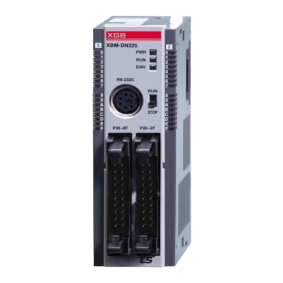
Page 20: Name And Function Of Each Part
Chapter 2 specification 2.3 Name and Function of each part XBM “S” Type XBM-DR16S XBM-DN16/32S ⑦ ⑦ ⑥ ① ⑥ ① ② ② ⑤ ⑤ ③ ④ ③ ④ ⑧ Name Purpose Input indication LED Input indication LED ① PADT connection PADT connection connector ②... - Page 21 Chapter 2 specification XBC/XEC “E” type XBC-DR10E XEC-DN10E XBC-DN10E XEC-DN14E XBC-DP10E XEC-DN20E XBC-DR14E XEC-DN30E XBC-DN14E XEC-DP10E XBC-DP14E XEC-DP14E XBC-DR20E XEC-DP20E XBC-DN20E XEC-DP30E XBC-DP20E XEC-DR10E XBC-DR30E Name Purpose Input indication LED Input indication LED ① PADT connection PADT connection RS-232C 1 channel connector ②...
- Page 22 Chapter 2 specification XBC/XEC “S/SU” type XBC-DN20S(U) XEC-DN20SU XBC-DR20SU XEC-DN30SU XEC-DN40SU XBC-DN30S(U) XBC-DR30SU XEC-DN60SU XEC-DR20SU XBC-DN40SU XBC-DR40SU XEC-DR30SU XBC-DN60SU Name Purpose Input indication LED Input indication LED ① PADT connection PADT connection USB(USB 1.1 supported) 1 channel, ② Notes 1) connector RS-232C 1 channel connector ③...
- Page 23 Chapter 2 specification XBC/XEC “H” type XBC-DR32H XEC-DN32H XBC-DN32H XEC-DN64H XBC-DR64H XEC-DP32H XBC-DN64H XEC-DP64H XEC-DR32H XEC-DR64H Name Purpose Input indication LED Input indication LED ① PADT connection PADT connection USB(USB 1.1 supported) 1 channel, ② connector RS-232C 1 channel connector ③...
- Page 24 Chapter 2 specification Extension Cnet module XBL-C41A XBL-C21A ① ① ② ③ Name Purpose LED indication Operation status indication ① RS-422/RS-485 Connector for connection with external device ② connector RS-232C connector Connector for connection with external device ③ LED name LED indication content LED status LED status content...
-
Page 25: Chapter 3 System Configuration
Chapter 3 System Configuration Chapter 3 System Configuration XGB PLC is having diverse product suitable for main system, computer link and network system configuration This chapter describes configuration method and characteristic. 3.1 XGB System Configuration System configuration of XGB PLC is as follows. Extension I/O module, in case of special module, in “S” type, up to 7 step connection and in “H”... -
Page 26: S" Type System Configuration
Chapter 3 System Configuration 3.1.2 “S” type System Configuration Main unit I/O module Special module Communication module Item Content XBM-DxxxS : 16 ~ 352 point I/O configuration point Max. 7 Digital I/O module Extension module Max. 7 connection available Analog module ... -
Page 27: Available System Configuration
Chapter 3 System Configuration 3.2 Available System Configuration Communication system by using XGB built-in communication function and Cnet module is diverse. In this chapter, it describes system configuration example. 3.2.1 1:1 Connection between PC (HMI) (No modem) PC (HMI) and Cnet I/F module is connected by RS-232C or RS-422/485 channel, PC (HMI) and PLC is connected by 1:1 without modem. - Page 28 Chapter 3 System Configuration (2) In case of using 1:1 connection with monitoring device such as XGT Panel XP series (LSIS) XGB main unit RS-485 I/F RS-232C I/F [Figure 3.2.2] 1:1 communication with HMI Wiring method (RS-232C) XGB main unit...
- Page 29 Chapter 3 System Configuration (3) In case of using 1:1 connection with XGB main unit XGB main unit XGB main unit RS-232C I/F RS-485 I/F [Figure 3.2.3] 1:1 communication between PLCs Wiring method XGB main unit XGB main unit XGB external Connection no.
-
Page 30: 1:1 Dedicated Modem Connection With Pc (Hmi)
Chapter 3 System Configuration 3.2.2 1:1 Dedicated modem connection with PC (HMI) It is 1:1 communication system connected through dedicated modem through RS-232C channel with PC (HMI). Normally, PC (HMI) acts as client station, Cnet I/F module acts as server station which respond request of PC (HMI). -
Page 31: Modem Connection With Pc And Communication Between Cnet I/F Modules
Chapter 3 System Configuration 3.3.3 Modem connection with PC and communication between Cnet I/F modules PC and Cnet #1 station is connected by modem through RS-232C channel Cnet #1 station ~ N station is communication between Cnet I/F module through RS-422 channel ... -
Page 32: Dedicated Communication With Pc (Hmi) And Different Type Rs-422 Communication
Chapter 3 System Configuration 3.2.4 Dedicated communication with PC (HMI) and different type RS-422 communication Null-modem communication by using PC (HMI) and RS-232C channel PC (HMI) acts as client station, Cnet I/F module acts as server, at this time, module setting acts as RS-232C XGT server ... -
Page 33: Optical Modem Communication For Moving Material Communication
Chapter 3 System Configuration 3.2.5 Optical modem communication for moving material communication Optical modem communication system for Cnet communication on material above moving linearly P2P communication or dedicated mode communication with monitoring device RS-232C/RS-422 communication with optical modem ... -
Page 34: Wireless Modem Communication For Communication Between Revolution Bodies
Chapter 3 System Configuration 3.2.6 Wireless modem communication for communication between revolution bodies RS-232C communication with wireless modem Communication between Cnet I/F module is dedicated/client communication RS-232C channel of Cnet I/F module is dedicated modem mode Wireless modem Wireless modem XGB PLC RS-232C... -
Page 35: Chapter 4 Basic Setting
Chapter 4 Basic Setting Chapter 4 Basic Setting 4.1 Setting Sequence of Product It describes installation of product and sequence. Install system by be operated by the following sequence. Operation sequence Equip Cnet I/F module to XGB system (It is applied in case of using external Cnet I/F module) ... -
Page 36: Plc Type Setting And How To Register Communication Module
Chapter 4 Basic Setting 4.2 PLC Type Setting and How to Register Communication Module To use Cnet I/F function, communication parameter should be written by XGP-PD. To set system about Cnet I/F module located in temporary position, register each module at XG-PD. Method on register Cnet I/F module is as follows according to On/Off line status. -
Page 37: How To Register Cnet I/F Module In Case Of Online
Chapter 4 Basic Setting [Figure 4.2.2] Cnet module registration screen 4.2.3 How to register Cnet I/F module in case of online If you register communication module at online status by using XG-PD, you should connect basic unit. After [Online]-> [Online] after doing communication setting by using “Connection setting” -> Selecting “Connection”... - Page 38 Chapter 4 Basic Setting At this time, in case registered module is different with currently connected module or type of communication module in the previous project, it shows whether it changes or not with the following message. [Figure 4.2.4] I/O information change message If you execute Read IO Information, equipped communication module like the following is indicated IO module information window.
-
Page 39: How To Set Basic Parameter
Chapter 4 Basic Setting 4.3 How to Set Basic Parameter Communication function used in Cnet I/F module is classified as followings. 1) Server mode service Without other program at PLC, you can read or write information in PLC and data. ... -
Page 40: Setting Item
Chapter 4 Basic Setting [Figure 4.3.1] Built-in communication standard setting screen 4.3.1 Setting item When setting Cnet communication parameter, the fact the user should define is as follows [Table 4.3.1] Item Setting content You can set from station 0 to station 255. Station no. -
Page 41: Setting Method
Chapter 4 Basic Setting *Parity bit Cnet I/F module can define three parity bits. Meaning of each parity bit is as follows. Parity bit type Meaning Reference None Not using parity bit Even If the number of 1 in one byte is even, parity bit becomes “0”. If the number of 1 in one byte is odd, parity bit becomes “1”. - Page 42 Chapter 4 Basic Setting [Figure 4.3.2] Communication module setting screen If standard communication parameter setting ends, download Cnet module. If you select [Online -> connection -> Write parameter], download is executed. After downloading, parameter is applied shortly. [Figure 4.3.3] Write Parameter screen...
-
Page 43: Chapter 5 Remote Connection
Chapter 5 Remote Connection Chapter 5 Remote Connection 5.1 Remote Connection 5.1.1 General In case PC executing XG500/XG-PD is far from XGB PLC, if you use remote connection function of Cnet I/F module, you can control remote PLC such as program download, upload, program debugging and monitor. - Page 44 Chapter 5 Remote Connection Remote connection sequence by using dial-up modem is as follows. (a) Cnet I/F module connected with PLC setting 1) Sets active mode of RS-232C channel of Cnet I/F as XGT server at XG-PD. 2) Sets Modem type of Cnet I/F module (RS-232C) as Dial-up modem and inputs atz in Modem Initialization.
- Page 45 Chapter 5 Remote Connection 2) Select settings of “Connection settings” and set detail of modem [Figure 5.1.4] Modem detail setting screen Note Baud rate in modem settings means communication speed between PC and modem, not communication speed of modem. Baud rate of modem means communication speed between modem and modem, it is set automatically according to quality of public line and destination modem’s speed.
- Page 46 Chapter 5 Remote Connection Remote 2 Remote 1 Communication Communication module module Public line Public line Tandem center [Figure 5.1.5] Modem remote 2 setting screen 5) Select connection on online after setting connection option, modem initialization dialog box shows and modem is initialized. 6) In case setting of COM channel of modem or connection with modem is wrong or, the error message shows.
- Page 47 Chapter 5 Remote Connection 7) If making phone call is complete, XG5000 tries remote connection. In case remote connection is complete, “Online” menu is activated. 8) This case is same with connection status where connection is established through RS-232C cable. Here you can use all function of online menu. Note After remote connection, you can use online menu of XG5000 like local connection.
- Page 48 Chapter 5 Remote Connection (2) Dedicated modem connection The following figure indicates that PC and Cent module is connected by dedicated modem through dedicated line. Dedicated line [Figure 5.1.6] XG5000 remote connection example by dedicated modem [Figure 5.1.6] is example of dedicated modem connection by dedicated line. You can use wireless modem, optical modem other than dedicated modem.
- Page 49 Chapter 5 Remote Connection 2) In case of setting depth as remote 2, set settings related with remote 1, 2 at the “Detail” window like the followings. [Figure 5.1.8] dedicated modem remote 2 setting screen 3) After completing setting, if you click connection of connection setting, XG5000 tried remote connection.
-
Page 50: Remote Connection Between Cnet I/F Modules
Chapter 5 Remote Connection 5.1.3 Remote connection between Cnet I/F modules (1) Remote connection through dedicated modem [Figure 5.1.13] indicates that XG5000 and local PLC is connected through RS-232C cable and in case RS-232C channel of Cnet I/F module equipped at local PLC communicates with Cnet I/F module of remote PLC through dedicated modem. - Page 51 Chapter 5 Remote Connection (b) Cnet I/F module setting connected at local PLC 1) Converts local connected PLC to Stop mode Note Basic parameter of remote server connected through XG5000 should be set as server. In case of remote client, it should be set as P2P client. In case there are many communications, if you try to remote connection, you may fail.
- Page 52 Chapter 5 Remote Connection b) Select depth as remote 1 and click “Settings” for detail setting. In the detail window, set station number. AS for station number, input station number set in Cnet I/F module to execute remote connection. Figure is case Cnet station number is set as 1. [Figure 5.1.13] XG5000 remote 1 connection setting screen c) XG5000 tries remote connection and in case remote connection is complete, online related function is activated.
- Page 53 Chapter 5 Remote Connection (d) In case of optical modem, wireless modem other than dedicated modem, communication media is only different, method of remote connection is same. [Figure 5.1.14] indicates remote connection by wireless modem. As for connection method, it is same with method of remote connection between Cnet I/F module by using communication.
- Page 54 Chapter 5 Remote Connection (2) Remote connection by RS-422/485 [Figure 5.1.15] indicates XG5000 and local PLC is connected into CPU module by RS-232C cable, in case RS-422/485 channel of Cnet I/F module connected at local PLC communicates, it is figure indicating remote connection example to remote PLC.
-
Page 55: Chapter 6 Server Function And P2P Service
Chapter 6 Server function and P2P service Chapter 6 Server function and P2P service 6.1 Server Modbus Service 6.1.1 General Dedicated service is built-in service in Cnet I/F module. Without specific program at PLC, you can read or write information and data from PC and other device. It acts as server at communication network and if read, write request conforming XGT dedicated protocol or Modbus protocol come, it responds. -
Page 56: Xgt Dedicated Server
Chapter 6 Server function and P2P service 6.1.2 XGT dedicated server It is used in case of communication between our products by our dedicated service, all characters are configured as ASCII code. In case of using multi drop, up to 32 stations can be connected. In case of setting station number, duplicated station number should not be set. - Page 57 Chapter 6 Server function and P2P service Max. no. of response Code Purpose Address data Read Coil Status 0XXXX 2000 Coils Read Input Status 1XXXX 2000 Coils Read Holding Registers 4XXXX 125 Registers Read Input Registers 3XXXX 125 Registers Force Single Coil 0XXXX 1 Coil Preset Single Register...
-
Page 58: P2P Service
Chapter 6 Server function and P2P service Since address of Modbus 1~9999 (decimal number), size of bit IO area is 9999/8=1249.875 byte (Namely 1249, byte should be integer unit). Also size of word IO area is 9999*2=19998 byte. In case the user set 0 as base address of bit output (0XXXX) area, Modbus bit area 00001 corresponds 0 byte 0 bit, 00002 corresponds 0... -
Page 59: P2P Parameter Configuration
Chapter 6 Server function and P2P service 6.2.2 P2P parameter configuration To use P2P service, the user executes the setting for the wanted operation at the P2P parameter window. Like the following figure, P2P parameter consists of three information. [Figure 6.2.2] P2P parameter configuration screen 1) P2P channel ... - Page 60 Chapter 6 Server function and P2P service [Figure 6.2.3] P2P channel setting screen Driver selectable in XGB Cnet and meaning are as follows. Driver Meaning None Not using P2P service User frame definition In case of transmitting/receiving user frame definition XGT client Select in case of executing read, write of XGT memory.
-
Page 61: Block Information
Chapter 6 Server function and P2P service 6.2.4 Block information If you select P2P block of each parameter at P2P parameter setting window, P2P block setting window shows. [Figure 6.2.4] P2P block setting screen You can set up to 32 independent blocks. If you select temporary block, you can designate each block operation by selecting instruction. - Page 62 Chapter 6 Server function and P2P service Setting item per each instruction and meaning are as follows. 1) Read instruction It is instruction when reading and saving temporary area of partner station. It is used equally without reference to driver. The basic configuration is as follows. [Figure 6.2.6] Variable setting screen of P2P Read instruction Item Description...
- Page 63 Chapter 6 Server function and P2P service 2) Write instruction Instruction used to write data to wanted area about destination station and this is used commonly regardless of driver type. Basic configuration is as follows. Item Description Reference Channel Designates channel to communicate Main unit built-in setting (Channel 1 : RS-232C, channel 2 : RS-485)
- Page 64 Chapter 6 Server function and P2P service Before using this instruction, you should define frame to send. [Figure 6.2.8] P2P Send instruction setting screen Item Setting content Reference Channel Designates communication channel Conditional flag Sets transmission conditional flag Frame is already registered at transmission Frame Designates transmission frame name frame...
-
Page 65: User Defined Frame Information
Chapter 6 Server function and P2P service 6.2.5 User defined frame information In case of sending frame the user wants or receiving some frame in network, you should define send/receive frame. It is available in P2P service. All frames consist of Head, Body, Tail and each can be omitted. User defined frame in XGB series is indicated group name and frame name and each meaning is as follows. - Page 66 Chapter 6 Server function and P2P service 3) Segment - Head, Body, Tail of frame consist of diverse segment, you can register to the following frame edit window. [Figure 6.2.12] Frame HEAD segment setting screen - Numerical constant, String constant, fix sized variable, variable sized variable in segment consisting frame.
- Page 67 Chapter 6 Server function and P2P service B) String Constant - Register String Constant among frame - Value of data is ASCII value. [Figure 6.2.15] Add string constant segment screen C) Fix sized variable - It is available at Body area of reception frame - Used in case of processing data as size as defined among received frame - Size is byte unit - Transmits/receives data as ASCII...
- Page 68 Chapter 6 Server function and P2P service D) Variable sized variable Available at Body area of TX/RX frame - Transmission frame ▪Used in case of changing length of frame ▪If checking “Assign memory”, it makes transmission frame by data read from PLC memory - Reception frame ▪Used in case of processing variable sized variable among received frame...
- Page 69 Chapter 6 Server function and P2P service [Figure 6.2.18] Segment variable sized variable conversion setting screen When configuring transmission frame, it uses 2 words of PLC memory M100 and in case of changing Hex to ASCII, in case h34353637 is saved M100, each segment of transmission frame changes into “h4567”.
- Page 70 Chapter 6 Server function and P2P service First, add group of transmission frame [Figure 6.2.19] Transmission frame group add screen If group edit window shows like the following, insert group name and select frame type “Transmission”. [Figure 6.2.20] transmission frame group setting screen You can register diverse frame about each group.
- Page 71 Chapter 6 Server function and P2P service By using frame edit window, you can register Head, Body, Tail [Figure 6.2.22] transmission frame edit window Only one Head and Tail exist about group but you can register many Bodies. Also you can omit Head and Tail but one Body is necessary.
- Page 72 Chapter 6 Server function and P2P service [Figure 6.2.25] Transmission frame Tail registration screen The following is screen where transmission frame registration is complete. [Figure 6.2.26] transmission frame setting complete screen 6) Reception frame In case of receiving temporary frame, first you should define reception frame. In case of receiving ACK, NAK response reception frame, registration method is as follows.
- Page 73 Chapter 6 Server function and P2P service First, to register frame, add group as “ACK”, “NAK”. [Figure 6.2.27] ACK, NAK reception group registration screen about wSB request frame ▪Adds frame registered reception frame group “ACK”. A) Head registration [Figure 6.2.28] ACK reception frame Head registration screen B) Body registration Registers at Body about data to process and instruction among reception frame [Figure 6.2.29] ACK reception frame Body registration screen...
- Page 74 Chapter 6 Server function and P2P service B) Body registration Registers at Body about data to process and instruction among reception frame In case you know size of data to save among reception frame, use fix sized variable and in case you don’t know size of data, use variable sized variable.
-
Page 75: P2P Service Operation
Chapter 6 Server function and P2P service 6.2.6 P2P service operation If P2P parameter setting ends, you should download PLC CPU parameter and start P2P service. We assume that P2P parameter to download is written and PLC is connected with CPU. 1) P2P parameter download If you select “Online”... - Page 76 Chapter 6 Server function and P2P service [Figure 6.2.36] P2P enable setting screen In the “Enable Link (HS Link, P2P)” window, select P2P parameter. Already checked P2P parameter is under operation. If you uncheck, P2P service stops. If you like to know whether P2P service is normal or not, select “Online -> System diagnosis”. For this function, refer to “Chapter 9.
-
Page 77: Chapter 7 Xgt Dedicated Protocol
XGT Dedicated Protocol 7.1.1 General XGT series dedicated protocol communication is function executing communication by our dedicated protocol. User can configure the intended communication system between our products without special setting by using reading/writing data of internal device area and monitoring function. -
Page 78: Frame Structure
Chapter 7 XGT Dedicated Protocol 7.1.2 Frame structure (1) Base format (a) Request frame (external communication device → XGB) Header Station Command Tail Frame check Command Structurized data area (ENQ) number type (EOT) (BCC) (b) ACK response frame (XGB → external communication device, when receiving data normally) Header Station Command... -
Page 79: List Of Commands
Chapter 7 XGT Dedicated Protocol (2) Command frame sequence ▪ Sequence of command request frame Stati Comma Formatted data Station Command Formatted data (PLC ACK response) Station Command Formatted data (PLC NAK response) 7.1.3 List of commands List of commands used in dedication communication is as shown below. Command Classification Main command... -
Page 80: Data Type
Chapter 7 XGT Dedicated Protocol 7.1.4 Data type It’s possible to read and write device in built-in communication. When device is used, be aware of data type. Data type of device • Available types of device - XBM-DXXXS and XBC-DXXXH Device “S”... - Page 81 Chapter 7 XGT Dedicated Protocol When device is designated, attach ‘%’ (25H) in front of the marking characters. (‘%’ is stands for starting of device.) Marking Data type Examples characters X(58H) %PX000,%MX000,%LX000,%KX000,%CX000,%TX000,%FX000 etc. Byte B(42H) %PB000,%MB000,%LB000,%KB000,%CB000,%TB000,%FB000 etc. %PW000,%MW000,%LW000,%KW000,%CW000,%TW000,%FW000, Word W(57H) %DW000 etc.
-
Page 82: Detail Of Instruction
Chapter 7 XGT Dedicated Protocol 7.1.5 Detail of instruction (1) Individual reading of device (R(r)SS (a) Purpose This is a function that reads PLC device specified in accord with memory data type. Separate device memory can be read up to 16 at a time. (b) PC request format Number Format... - Page 83 Chapter 7 XGT Dedicated Protocol (c) XGB response format (ACK response) Number Number of Frame Format name Header Station No. Command Command type data Tail of blocks data check ..Ex. of frame ACK R(r) HA9F3 ASCII value H06 H3230 H52(72) H5353 H3031 H3032 H41394633...
- Page 84 Chapter 7 XGT Dedicated Protocol (d) XGB response format (NAK response) Heade Station Error code Format name Command Command type Tail Frame check (Hex 2 Byte) Ex. of frame R(r) H1132 ASCII value H3230 H52(72) H5353 H31313332 Item Explanation When command is lowercase(r), only one lower byte of the value resulted by adding 1 Byte each to ASCII values from NAK to ETX is converted into ASCII and added to BCC.
- Page 85 Chapter 7 XGT Dedicated Protocol (2) Direct variable continuous reading (R(r)SB) (a) Purpose This is a function that reads the PLC device memory directly specified in accord with memory data type. With this, data is read from specified address as much as specified continuously. (b) PC request format Format Station...
- Page 86 Chapter 7 XGT Dedicated Protocol Item Description It means byte number of hex type, and is converted into ASCII Data type Available device Data size (Byte) BYTE(B) %(P,M,L,K,F,T,C,D,R,I,Q,W)B WORD(W) %(P,M,L,K,F,T,C,D,R,I,Q,W)W Number of data DWord(D) %(P,M,L,K,F,T,C,D,R,I,Q,W)D LWord(L) %(P,M,L,K,F,T,C,D,I,Q,W)L ※R area is supported at XBC-DXXXH ▪Example 1 When memory type included in variable name of computer request Format is W (Word), and data number of computer request Format is 03, data number of PLC ACK response after...
- Page 87 Chapter 7 XGT Dedicated Protocol For NAK response after execution of command (PC ← XGB) Format name Header Station No. Command Command type Error code Tail Frame (Example) R(r) Error code (2 Byte) ASCII value H3041 H52(72) H5342 Error code (4 Byte) 7-11...
- Page 88 Chapter 7 XGT Dedicated Protocol (3) Individual writing of device (W(w)SS) (a) Purpose This is a function that writes the PLC device memory directly specified in accord with memory data type. (b) PC request format Frame Number of Device Command ..
- Page 89 Chapter 7 XGT Dedicated Protocol (c) XGB Response format (ACK response) Tail Frame check Format name Header Station No. Command Command type Frame (Example) W(w) ASCII value H3230 H57(77) H5353 Item Description When command is lowercase (r), only one lower byte of the value resulted by adding 1 Byte each to ASCII values from ACK to ETX is converted into ASCII and added to BCC, and sent.
- Page 90 Chapter 7 XGT Dedicated Protocol (4) Continuous writing of device (W(w)SB) (a) Purpose This is a function that directly specifies PLC device memory and continuously writes data from specified address as much as specified length. (b) Request format Format Head Station Number Frame...
- Page 91 Chapter 7 XGT Dedicated Protocol (d) XGB Response format (NAK response) Format name Header Station No. Error code (Hex 2 Byte) Tail Frame check Command Command type Frame (Example) W(w) H1132 ASCII value H3130 H57(77) H5342 H31313332 Item Description When command is lowercase(r), only one lower byte of the value resulted by adding 1 Byte each to ASCII values from NAK to ETX is converted into ASCII and added to BCC, and sent.
- Page 92 Chapter 7 XGT Dedicated Protocol (5) Monitor variable register (X##) (a) Purpose Monitor register can separately register up to 16 (from 0 to 15) in combination with actual variable reading command, and carries out the registered one through monitor command after registration. (b) PC request format Head Station...
- Page 93 Chapter 7 XGT Dedicated Protocol (d) XGB Response format (NAK response) Registratio Error code Format name Header Station No. Tail Frame check Command n No. (Hex 2Byte) Frame (Example) X(x) H1132 ASCII value H3130 H58(78) H3039 H31313332 Item Description When command is one of lower case(x), only one lower byte of the value resulted by adding 1 Byte each to ASCII values from NAK to ETX is converted into ASCII and added to BCC, and sent.
- Page 94 Chapter 7 XGT Dedicated Protocol (6) Monitor execution (Y##) (a) Purpose This is a function that carries out the reading of the variable registered by monitor register. This also specifies a registered number and carries out reading of the variable registered by the number. (b) PC request format Format name Header...
- Page 95 Chapter 7 XGT Dedicated Protocol (e) Example This example supposes that registered device No. 1 of station No. 1 is read. and BCC value is checked. And it is supposed that device M000 is registered and the number of blocks is 1. 1) PC request format (PC →...
-
Page 96: Chapter 8 Ls Bus Protocol
Chapter 8 LS Bus Protocol Chapter 8 LS Bus Protocol 8.1 LS Bus Protocol LS Bus Protocol communication is function executing communication between XGB Cnet and LS Inverter. User can configure LS Bus communication system between our products without special setting by using reading/writing data of internal device area and monitoring function. -
Page 97: List Of Commands
Chapter 8 LS Bus Protocol Command frame sequence ▪ Sequence of command request frame Station Command Formatted data BCC Station Command Formatted data BCC (Inverter ACK response) Station Command Formatted data BCC (Inverter NAK response) 8.1.2 List of commands List of commands used in LS Bus communication is as shown below. Classification Command Command type... -
Page 98: Detail Of Instruction
Chapter 8 LS Bus Protocol 8.2 Detail of instruction 8.2.1 Continuous writing to inverter device (W) This command is to write PLC data in specified address of inverter. LS Bus Client Request format Format Station Device Address of Frame Header Command Data... - Page 99 Chapter 8 LS Bus Protocol Inverter Response format(ACK response) Station Format name Header Command Data Frame check Tail Frame (Example) H00E2 … ASCII value H3230 H30304532 Item Description When ASCII value of each 1byte except ENQ and EOT is summed, the lowest 1byte of the result value is BCC.
-
Page 100: Inverter Continuous Reading (R)
Chapter 8 LS Bus Protocol 8.2.2 Inverter continuous reading (R) This is a function of continuous reading of designated amount of PLC data from designated address number. PC Request format Station Address of Frame Format name Header Command Number of data Tail inverter check... - Page 101 Chapter 8 LS Bus Protocol Inverter response format (ACK response) Station Format name Header Command Data Frame check Tail Frame (Example) H00E2 … ASCII value H3230 H30304532 Item Description When ASCII value of each 1byte except ENQ and EOT is summed, the lowest 1byte of the result value is BCC.
-
Page 102: Chapter 9 Modbus Communication
Chapter 9 Modbus Communication Chapter 9 Modbus Communication 9.1 General Modbus protocol is specified open protocol used between client-server, which executes reading/writing data according to function code. Communication between devices that use Modbus protocol uses Client-server function in which only one client processes the data. 9.2 Modbus Protocol 9.2.1 Kind of modbus protocol There are two communication modes of Modbus, ASCII and RTU. - Page 103 Chapter 9 Modbus Communication In case of abnormal communication, process step is as follows. When receiving the abnormal frame from client, server transmits error code and exceptional code. Error code is function code adding 80(Hex) and exceptional code indicate the specific error content. Each code has following content.
-
Page 104: Structure Of Frame
Chapter 9 Modbus Communication 9.3 Structure of Frame 9.3.1 Structure of frame in the ASCII mode Frame structure in the ASCII mode is as follows. Classification Start Station no. Function code Data Error check Size (byte) (1) Characteristic of ASCII mode (a) In the ASCII mode, start of frame is indicated with colon (:), which is ASCII code, and end of frame is indicated with ‘CRLF’. -
Page 105: Data And Expression Of Address
Chapter 9 Modbus Communication (4) Error check area It determines if frame is normal or not by using CRC check of 2 byte. (5) Modbus address regulation Address in the data starts from 0 and it is same with value that is minus 1 from modbus memory, Modbus address 2 is same with address 1 of data. -
Page 106: Modbus Protocol
Chapter 9 Modbus Communication 9.4 Modbus Protocol 9.4.1 Reading data of bit type at the bit output (01) (1) Reading bit of output area (function code: 01) In case of reading data of bit type, request and response frame is as follows. Detail of frame is applied in case of ASCII mode. - Page 107 Chapter 9 Modbus Communication (3) Frame example Example that requests reading bit of 20~28 to station number 1 server acting as modbus RTU mode (a) Request frame Address Data size Function Classification Station no. Error check code Upper byte Lower byte Upper byte Lower byte Frame...
-
Page 108: Read Input Status (02)
Chapter 9 Modbus Communication 9.4.2 (02) Read Input Status (1) Reading bit of input area In case of reading data of bit type of input area, request and response frame is as follows. Tail of frame is applied in case of ASCII mode. (a) Request frame Station Function code... -
Page 109: Read Holding Registers (03)
Chapter 9 Modbus Communication 9.4.3 Read Holding Registers (03) (1) Reading word of output area When reading data of word type of output area, request and response frame is as follows. Tail of frame is applied in case of ASCII mode. (a) Request frame Station Function code... -
Page 110: Read Input Registers (04)
Chapter 9 Modbus Communication 9.4.4 Read Input Registers (04) (1) Reading word of input area In case of reading word of input area, request and response frame is as follows. Tail of frame is applied in case of ASCII mode. (a) Request frame Station Function code... -
Page 111: Force Single Coil (05)
Chapter 9 Modbus Communication 9.4.5 Force Single Coil (05) (1) Writing single bit of output area When writing single bit of output area, request and response frame is as follows. Tail of frame is applied in case of ASCII mode. (a) Request frame Function Frame error... -
Page 112: Preset Single Register (06)
Chapter 9 Modbus Communication 9.4.6 Preset Single Register (06) (1) Writing single word of output area In case of writing single word to output area, request and response frame is as follows. Detail of frame is applied in case of ASCII mode. a) Request frame Station Function code... -
Page 113: Force Multiple Coils (0F)
Chapter 9 Modbus Communication 9.4.7 Force Multiple Coils (0F) (1) Writing continuous bit to output area In case of writing continuous bit to output area, request and response frame is as follows. Tail of frame is applied in case of ASCII mode. (a) Request frame Frame Station... - Page 114 Chapter 9 Modbus Communication (3) Frame example Example writing 10 continuous bits starting 20 address of 1 server acting as Modbus RTU mode Ex.) Data value to write continuously Bit value Address (a) Request frame Error Address No. of output Output Classifica Station...
-
Page 115: Preset Multiple Registers (10)
Chapter 9 Modbus Communication 9.4.8 Preset Multiple Registers (10) (1) Writing word continuously to output area In case of writing word continuously to output area, request and response frame is as follows. Tail of frame is applied in case of ASCII mode. (a) Request frame Frame Station... - Page 116 Chapter 9 Modbus Communication (3) Frame example Example writing continuous 2 words starting 20 address of server 1acting as Modbus RTU mode Ex.) value to write continuously Address (a) Request frame Address No. of output Classific Station Functio Data Error Upper Lower Upper...
-
Page 117: Chapter 10 Example Program
Chapter 10 Example Program Chapter 10 Example Program 10.1 Setting of Cnet I/F module in the XG-PD Operation of XGT Cnet I/F is divided into P2P service and Server. • P2P service: acts as client (master) and request reading/writing. - XGT client - Modbus RTU/ASCII client - User frame definition •... - Page 118 Chapter 10 Example Program Sequence Procedure Setting method Selecting 1. Select active mode of server for user to use. the active 2. XGB Cnet I/F module supports XGT server, Modbus ASCII server, Modbus mode RTU server. Writing parameter 1. Select [Online] – [Write Parameter] or click icon ( 2.
-
Page 119: In Case Of Acting As P2P Service (Client)
Chapter 10 Example Program 10.1.2 In case of acting as P2P service (client) Sequence Procedure Setting method Standard 1. Step 1~3 is same as described above. settings *In case of ASCII client, data bit should be 7. Active mode 1. Select Use P2P settings as active mode. Double-click settings 1. - Page 120 Chapter 10 Example Program Sequence Procedure Setting method P2P block setting 1. P2P items are activated differently according to type of client set in the channel. 2. Write shell according to protocol * In case of user definition frame, P2P block can be set when user definition frame is written.
- Page 121 Chapter 10 Example Program Sequence Procedure Setting method Checking operation 1. Select [Online] – [System Diagnosis] or click icon ( 2. Click the right button on the relevant module and click Frame Monitor or Status By Service to check. 10-5...
-
Page 122: Dedicated Communication Example
Chapter 10 Example Program 10.2 Dedicated Communication Example Dedicated communication? • As defined protocol by LSIS, it is classified XGT client and XGT server • XGT client: requests reading/writing of data to server • XGT server: responds according to request of client We assume that system configuration of dedicated service example is as [Figure 10.2.1] and... -
Page 123: Settings Of Xgt Server
Chapter 10 Example Program 10.2.1 Settings of XGT server Setting method to operate built-in RS-232C communication channel of XBC-DN32H as server is as follows. Sequence Procedure Setting method Connection settings 1. Select [Online]-[Connection settings] and click ( 2. After setting the connection option according to user, click the ‘connection’. Reading IO Select [Online]-[Read IO Information] and click icon ( information... -
Page 124: Settings Of Xgt Client
Chapter 10 Example Program 10.2.2 Settings of XGT client To operate XBL-C21A of client as XGT client, set Cent I/F module as follows. Sequence Procedure Setting method Connection settings 1. Select [Online]-[Connection settings] or click icon ( 2. After setting the connection option according to user, click the ‘connection’. Select [Online]-[Read IO Information] and click icon ( Reading IO information... - Page 125 Chapter 10 Example Program After standard settings, P2P channel and P2P block should be set. Setting methods are as follows. Sequence Procedure Setting method P2P setting Click P2P bottom of project window. Communic ation module settings 1. Double-click of project window. (P2P 01 is fixed as built-in communication module) 2.
- Page 126 Chapter 10 Example Program Sequence Procedure Setting method Writing parameter 1. Select [Online] – [Write Parameter] or click icon ( 2. Click [OK]. 3. If writing parameter is complete After clicking [OK], changed parameter is applied automatically. Enabling the link 1.
-
Page 127: Checking The Operation
Chapter 10 Example Program 10.2.3 Checking the operation The user can analyze frame by using the frame monitor of XG-PD to check it communication is normal or not. Method of frame monitor of Cnet I/F module is same regardless of protocol. Sequence Procedure Setting method... -
Page 128: Modbus Communication Example
Chapter 10 Example Program 10.3 Modbus Communication Example We assume that system configuration of Modbus communication (Modbus RTU mode) example is as [Figure 10.3.1] and communication setting is as following table. RS-485, 38400, 8, 1, None, Modbus RTU Client Server [Figure 10.3.1] XGT Modbus communication system configuration example •... -
Page 129: Modbus Rtu Server Setting
Chapter 10 Example Program 10.3.1 Modbus RTU server setting Standard settings are as follows to act built-in RS-485 communication channel of XBC-DN32H as Modbus RTU server. Sequence Procedure Setting method Connection setting 1. Select [Online]-[Connection settings] or click icon ( 2. - Page 130 Chapter 10 Example Program Sequence Procedure Setting method Writing parameter 1. Select [Online] – [Write Parameter] or click icon ( 2. Click [OK] 3. If writing parameter is complete after clicking [OK] button, changed parameter is applied automatically. 10-14...
-
Page 131: Setting Of Modbus Rtu Client
Chapter 10 Example Program 10.3.2 Setting of Modbus RTU client Standard settings are as follows to act XBL-C41A of client as Modbus RTU client. Sequence Procedure Setting method Connection setting 1. Select [Online]-[Connection settings] or click icon ( 2. After setting the connection option according to user, click the ‘connection’. Select [Online]-[Read IO Information] and click icon ( Reading IO information... - Page 132 Chapter 10 Example Program After standard settings, P2P channel and P2P block should be set. Setting methods are as follows. Sequence Procedure Setting method P2P setting Click bottom of project window. Communic ation module setting 1. Double-click of project window. (P2P 01 is fixed as built-in communication) 2.
- Page 133 Chapter 10 Example Program Sequence Procedure Setting method Setting of writing operation (3) ▶ Write 15 bit of M2 to 2 bit of M20 of server 1. Ch., P2P function, conditional flag, destination station no.: same with step 5 2. Data type: select bit 3.
- Page 134 Chapter 10 Example Program Sequence Procedure Setting method Setting of reading operation (2) ▶ Read 4 words from P0 of server and save it at M150~M153 1. Ch., Conditional flag, Command type, Data type, Destination station no.: same with step 6 2.
- Page 135 Chapter 10 Example Program Sequence Procedure Setting method Writing parameter 1. Select [Online] – [Write Parameter] or click icon ( 2. Click [OK]. 3. If writing parameter is complete after click OK, changed parameter is applied automatically. Enabling the link 1.
-
Page 136: User Defined Communication Example
Chapter 10 Example Program 10.4 User - defined Communication Example 10.4.1 User-defined communication example system configuration When communication with device of which protocol is not supported by Cnet I/F module client, how to use user-defined communication is described in the system like [Figure 10.4.1] below •... -
Page 137: User Definition Communication Frame Structure
Chapter 10 Example Program 10.4.2 User definition communication frame structure Frame structure of PC Link, communication protocol of Han-Young used in this example, is as follows. • Frame of temperature controller is executed as ASCII character string, it can read/write defined D, I Register. -
Page 138: User Definition Communication Parameter Setting
Chapter 10 Example Program 10.4.3 User definition communication parameter setting (1) Communication standard parameter setting For standard setting, refer to setting method when acting as P2P service of 10.1.2 and configure above system [Table 10.4.1]. (2) Writing frame that requests reading data Describes how to write frame at XG-PD for user definition communication frame that requests reading data (Transmission frame) Sequence... - Page 139 Chapter 10 Example Program Sequence Setting method 1. Select Numerical constant which indicates Hex as ASCII code as Form. Input Hex value D, A which indicates CR and LF. 1. Double-click DRS.test tap and edit segment like the following. 2. Write frame requesting reading data of continuous 2 areas starting first of D register of station no.1.
- Page 140 Chapter 10 Example Program (3) Writing frame to receive response frame of temperature controller Writing response frame (Reception frame) Sequence Setting method 1. Write like step 2 of frame that request reading data. At this time, set Frame type as reception. 2.
- Page 141 Chapter 10 Example Program (4) Writing P2P transmission/reception block Write P2P TX/RX block as follows by using user definition communication segment written ahead. Sequence Setting method 1. Double-click P2P block of P2P 01. 2. Input channel selected at P2P channel (user frame definition). 3.
-
Page 142: Chapter 11 Diagnosis
Chapter 11 Diagnosis Chapter 11 Diagnosis With XG-PD used, the status of the system and the network can be checked and diagnosed. Diagnosis function is composed as described below ▶ CPU module information ▶ Communication module information ▶ Frame monitor ▶... -
Page 143: Checking Status Of Main Unit
Chapter 11 Diagnosis 11.1.1 Checking status of main unit Check list Detail result Module information 1. Select [Online] – [System Diagnosis] or click the icon ( 2. You can check the status of main unit by clicking CPU module information after clicking main unit. -
Page 144: Frame Monitor
Chapter 11 Diagnosis 11.1.3 Frame monitor The user can check whether frame is normal or not by monitoring TRX frame through Cnet I/F module by XG-PD’s frame monitor. Check list Detail result Frame monitor 1. Select [Online] – [System Diagnosis] or click the icon ( 2. -
Page 145: Status By Service
Chapter 11 Diagnosis 11.1.4 Status by service Check list Detail result Dedicated service 1. Select [Online] – [System Diagnosis] or click the icon ( 2. Click the right button on the the Cnet I/F module and click Status By Service. 3. - Page 146 Chapter 11 Diagnosis 1. Select [Online]->[System diagnosis] or click the icon ( 2. Click the right button on the the Cnet I/F module and click Status By Service. 3. Click P2P service of Status by Service 4. Click mutiple reading and check Status by Service. Classification Item Contents...
-
Page 147: Trouble Shooting By Error
Chapter 11 Diagnosis 11.2 Trouble Shooting by Error 11.2.1 Trouble shooing when P2P parameter setting error occurs in case of XG5000 connection Phenomenon Reason Trouble shooting P2P setting error warning in case of XG5000 connection 1. In Enable Link menu of In case of enabling XG5000, check P2P setting link, the user... -
Page 148: Two Response Frame Are Dealt With As Unknown When Executing Frame Monitor--11-7
Chapter 11 Diagnosis 11.2.4 Two response frame are dealt with as unknown when executing frame monitor Phenomenon Reason Trouble shooting Communication Two response frame are dealt with as unknown when type in XG-PD is Change executing frame monitor set as RS-422 communication type but output wiring as RS-485 and write... -
Page 149: Communication Is Not Normal Or Communication Is Not Executed Repeatedly
Chapter 11 Diagnosis 11.2.7 Communication is not normal or communication is not executed repeatedly Phenomenon Reason Trouble shooting 1. Execute 1:1 communication with In case of multi drop, server and check if it works More than one server properly. sends frame 2. -
Page 150: Chapter 12 Installation And Wiring
Chapter 12 Installation and Wiring Chapter 12 Installation and Wiring 12.1 Safety Instruction Danger Please design protection circuit at the external of PLC for entire system to operate safely because an abnormal output or an malfunction may cause accident when any error of external power or malfunction of PLC module. - Page 151 Chapter 12 Installation and Wiring Danger Don’t close the control line or communication cable to main circuit or power line. Distance should be more than 10mmm. It may cause malfunction by noise. In case of controlling lamp load, heater, solenoid valve, etc. in case of Off -> On, large current (10 times of normal current) may flows, so consider changing the module to module that has margin at rated current.
-
Page 152: Fail Safe Circuit
Chapter 12 Installation and Wiring 12.1.1 Fail safe circuit (1) example of system design (In case of not using ERR contact point of power module) In case of AC In case of AC . DC Power Power Check direct Trans Trans current Trans... - Page 153 Chapter 12 Installation and Wiring (2) System design circuit example (In case of using ERR contact point of power module) Power Checking Trans Trans Fuse Fuse current Signal input F0045 DC power Start stop circuit Fuse F009C Timer setting PLC RUN output which DC input Available to start as signal...
- Page 154 Chapter 12 Installation and Wiring (3) Fail safe countermeasure in case of PLC error Error of PLC CPU and memory is detected by self diagnosis but in case error occurs in IO control part, etc., CPU can detect the error. At this case, though it is different according to status of error, all contact point is on or off, so safety may not be guaranteed.
-
Page 155: Plc Heat Calculation
Chapter 12 Installation and Wiring 12.1.2 PLC heat calculation (1) Power consumption of each part (a) Power consumption of module The power conversion efficiency of power module is about 70% and the other 30% is gone with heat; 3/7 of the output power is the pure power consumption. Therefore, the calculation is as follows. - Page 156 Chapter 12 Installation and Wiring (e) Input average power consumption of input module (power consumption of simultaneous On point) • W X E X input point X simultaneous On rate (W) : input current (root mean square value in case of AC) (A) E : input voltage (actually used voltage) (V) (f) Power consumption of special module power assembly •...
-
Page 157: Attachment/Detachment Of Modules
Chapter 12 Installation and Wiring 12.2 Attachment/Detachment of Modules 12.2.1 Attachment/Detachment of modules Caution in handling Use PLC in the range of general specification specified by manual. In case of using out of range, it may cause electric shock, fire, malfunction, damage of product. Warning ... - Page 158 Chapter 12 Installation and Wiring (2) Detachment of module • Get up the hook for fixation of upper part and lower part and disconnect it. • Detach the module with two hands. (Don’t force over-applied force.) Hook for module fixation Caution ...
- Page 159 Chapter 12 Installation and Wiring (3) Module equipment location Keep the following distance between module and structure or part for well ventilation and easy detachment and attachment. 30 ㎜ or above 20 ㎜ or above 30 ㎜ or above 5 ㎜ or above 5 ㎜...
- Page 160 Chapter 12 Installation and Wiring (b) Don’t install like the following figure (5) Distance with other device To avoid radiation noise or heat, keep the distance between PLC and device (connector and relay) as far as the following figure. ㎜ or above Device installed in front of PLC: 100 ㎜...
-
Page 161: Caution In Handling
Chapter 12 Installation and Wiring 12.2.2 Caution in handling Here describes caution from open to install • Don’t drop or impact product. • Don’t disassemble the PCB from case. It may cause the error. • In case of wiring, make sure foreign substance not to enter upper part of module. -
Page 162: Wire
Chapter 12 Installation and Wiring 12.3 Wire In case using system, it describes caution about wiring. Danger When wiring, cut off the external power. If all power is cut, it may cause electric shock or damage of product. In case of flowing electric or testing after wiring, equip terminal cover included in product. It not, it may cause electric shock. - Page 163 Chapter 12 Installation and Wiring (3) Isolate the PLC power, I/O devices and power devices as follows. Main unit Main power Constant power Voltage AC220V Transformer AC100-240V IO power Main circuit device (4) If using DC24V of the power module (a) Do not connect DC24V of several power modules in parallel.
- Page 164 Chapter 12 Installation and Wiring (8) To prevent surge from lightning, use the lightning surge absorber as presented below. I/O device Surge absorber to prevent Note (1) Isolate the grounding(E1) of lightning surge absorber from the grounding(E2) of the PLC. (2) Select a lightning surge absorber type so that the max.
-
Page 165: I/O Device Wiring
Chapter 12 Installation and Wiring I/O Device wiring 12.3.2 (1) The size of I/O device cable is limited to 0.3~2 mm but it is recommended to select a size(0.3 mm ) to use conveniently. (2) Please isolate input signal line from output signal line. (3) I/O signal lines should be wired 100mm and more away from high voltage/high current main circuit cable. -
Page 166: Channel Operation During Normal Run
Chapter 12 Installation and Wiring 12.4 Channel Operation during Normal Run In case of built-in Cnet, each communication port operates independently to allow simultaneous Tx/Rx in separate transmission specifications. In case of XBL-C21A/C41A, only one channel is available. In case of built-in Cnet, transmission specifications can be set per RS-232C and RS-422 channel, and the operation is started and stopped according to channels. -
Page 167: Communication Interface Connection Method
Chapter 12 Installation and Wiring 12.5 Communication Interface Connection Method 12.5.1 RS-232C Interface (XBL-C21A) Channel RS-232C uses 9-pin connector (Female) for communication with external devices. The names and functions of pins and data directions are as shown in the figure below. Signal Direction Pin No. - Page 168 Chapter 12 Installation and Wiring (1) How to connect RS-232C connector during modem connection (XBL-C21A) This module can communicate with devices of long distance as connected with modem. Modem and RS-232C channel shall be connected as in [Figure 12.5.2] below. Cnet (9-PIN) Modem side (25-PIN) Connection No.
-
Page 169: Rs-422/485 Interface (Built-In Communication)
Chapter 12 Installation and Wiring 12.5.2 RS-422/485 interface (Built-in communication) Built-in communication channel (RS-232C/RS-485) uses 5-pin connector (Terminal Block) for communication with external devices. The names and functions of pins and data directions are as shown in [Figure 12.5.4] below Signal direction Pin no. -
Page 170: Interface (Xbl-C41A)
Chapter 12 Installation and Wiring 12.5.3 RS-422 interface (XBL-C41A) RS-422 channel use 5 pin connector (Terminal Block) for communicate with external [Figure 12.5.7] indicates function of each pin name, function and data direction. Signal direction Pin no. Name Function description (Cnet<-->External device) TX data (+) TX data (-) - Page 171 Chapter 12 Installation and Wiring Single and multi-drop connection with external device are available in XBL-C41A. [Figure 12.5.10], [Figure 12.5.11] are RS-422/RS-485 multi drop communication connection method. Master (XBL-C41A) Connecti External slave Connecti External slave device#1 device#2 Pin no. Name S.G(SG) [Figure 12.5.10] RS-422 connection Master (XBL-C41A) Connection...
-
Page 172: Cable Specifications
Chapter 12 Installation and Wiring 12.6 Cable Specifications (1) When using communication channel, RS-422 or RS-485, twisted pair cable for RS-422 shall be used in consideration of communication distance and speed. (2) [Table 12.6.1] describes recommended specifications of cable. Also when using other cable than recommended, the cable conforming to characteristics in [Table 12.6.1] shall be used. - Page 173 Chapter 12 Installation and Wiring 12.7 Terminal Resistance (In case of using RS-422/485) (1) For communication via RS-422/RS-485 channel, terminal resistance from external must be connected. (2) Terminal resistance has the function to prevent distortion of signal by reflected wave of cable for long- distance communication, and the same resistance (1/2W) as characteristic impedance of cable must be connected to terminal of network.
-
Page 174: Chapter 13 Maintenance
Chapter 13 Maintenance Chapter 13 Maintenance Be sure to perform daily and periodic maintenance and inspection in order to maintain the PLC in the best conditions. 13.1 Maintenance and Inspection The I/O module mainly consist of semiconductor devices and its service life is semi-permanent. However, periodic inspection is requested for ambient environment may cause damage to the devices. -
Page 175: Periodic Inspection
Chapter 13 Maintenance 13.3 Periodic Inspection Check the following items once or twice every six months, and perform the needed corrective actions. Corrective Check Items Checking Methods Judgment Actions Ambient 0 ~ 55 °C Adjust to general temperature -. Measure with thermometer standard Ambient Ambient Humidity... -
Page 176: Appendix
Appendix 1 Definition of Terms Appendix 1 Definition of Terms Appendix 1.1 General Terms Describes PLC general terms used in this manual (1) Module A standard element with a specific function to structure a system such as I/O board assembled to be inserted into the motherboard base Ex) CPU module, power module, I/O module (2) Unit... -
Page 177: Appendix 1.2 Serial Communication Terms
Appendix 1 Definition of Terms Appendix 1.2 Serial Communication Terms Describes serial communication term (1) Communication type (a) Simplex This is the communication type that data is transferred in a constant direction. Information can not be transferred in the reverse direction. (b) Half-Duplex Data is transferred in two ways with one cable if time interval provided, though it can’t be transferred simultaneously. - Page 178 Appendix 1 Definition of Terms (b) Parallel transmission This type is used in printer, etc., which transmits data in unit of 1 byte, so the speed is high and the accuracy of data is reliable. However, the longer the transmission distance is, the higher the cost of installation is geometrically.
- Page 179 Appendix 1 Definition of Terms (4) Protocol This is communication rule established in relation between the transmission side and the receiving side of information in order to send and accept information between two computers/terminals or more without error, effectively, and reliably. In general, this specifies call establishment, connection, structure of message exchange form, re-transmission of error message, procedure of line inversion, and character synchronization between terminals, etc.
- Page 180 Appendix 1 Definition of Terms (11) Half Duplex Communication Two-way communication is available, however simultaneous communication of transmission & receiving isn’t available. This communication type is applied to RS-485 for instance. It is used a lot for multi-drop communication type which communicates via one signal line by several stations. Half Duplex Communication results from the transmission characteristic performed by stations one by one not allowing simultaneous transmission by multi stations due to the data damage of data impact caused by the simultaneous multi-transmission of the stations.
- Page 181 Appendix 1 Definition of Terms (13) BCC (Block Check Character) As serial transmission may have signals distorted due to undesirable noise in transmission line, BCC is used as data to help receiving side to check the signals if normal or distorted and to detect errors in signals as compared with the received BCC after calculating BCC by receiving side itself using the data input to the front terminal of BCC.
- Page 182 Appendix 1 Definition of Terms (15) Frame Frame is composed of transmitted and received data as in a specified form in data communication including additional information of segments [station No., command, parameter by command], control characters [ENQ, ACK, EOT, ETX] for synchronization, parity for detecting error, and BCC. The structure of frame used for serial communication of Cnet is as follows.
-
Page 183: Appendix 2 Communication Relay List (L
Appendix 2 Communication Relay List (L) Appendix 2 Communication Relay List (L) Appendix 2.1 Communication Relay (L) List Here describes data link communication relay(L). (1) High-speed Link 1 Device IEC type Keyword Type Description High speed link parameter 1 normal operation of all station Indicates normal operation of all station according to parameter set in High speed link, and On under the condition as below. - Page 184 Appendix 2 Communication Relay List (L) (2) High-speed Link 2 Device IEC type Keyword Type Description High-speed link parameter 2 normal operation of all station. Indicates normal operation of all station according to parameter set in High-speed link and On under the condition as below. 1.
- Page 185 Appendix 2 Communication Relay List (L) (3) Common area Communication flag according to P2P service setting In case of XGB, P2P parameter is 1~3, P2P block is 0~31. Device IEC type Keyword Type Description _P2P1_NDR0 Indicates P2P parameter 1, 0 Block service L5120 %LX8192 normal end.
-
Page 186: Appendix 2.2 Network Register (N) List
Appendix 2 Communication Relay List (L) Appendix 2.2 Network Register (N) List Here describes about network register ( P2P parameter: 1~3, P2P block: 0~31 ) Device IEC type Keyword Type Description N000 _P1B00SN Word %NW000 Saves another station no. of P2P parameter 1, 00 block. _P1B00RD %NW0001 N0000~0004... -
Page 187: Appendix 3 Communication Error Code
Appendix 3 Communication Error Code Appendix 3 Communication Error Code Appendix 3.1 XGT Server Error Code Error code is displayed as hex 2 byte (4 byte as ASCII code). The user can see error by frame monitor and in case of viewing by ASCII, the user can see the following error code. Error code Error type Error details and causes... -
Page 188: Appendix 3.2 Modbus Server Error Code
Appendix 3 Communication Error Code Appendix 3.2 Modbus Server Error Code Error code is displayed as hex 1 byte (2 byte as ASCII code) and indicates type of error. Code Error type Error details and causes Illegal Function Function code error Illegal Address Address range exceeded Illegal Data Value... -
Page 189: Appendix 4 Dimension (Unit: Mm
Appendix 4 Dimension Appendix 4 Dimension (Unit : mm) (1) Stand type main unit (“S”type) -. XBM-DN16S/32S XBM-DN16S RS-232C P00~07 P20~27 -. XBM-DR16S XBM-DR16S RS-232C P00~07 P20~27 A-14... - Page 190 Appendix 4 Dimension (2) Compact type main unit (“H” type) -. XBC-DN32H / XEC-DN32H -. XBC-DR32H / XEC-DR32H A-15...
- Page 191 Appendix 4 Dimension -. XBC-DN64H / XEC-DN64H -. XBC-DR64H / XEC-DR64H A-16...
- Page 192 Appendix 4 Dimension (3) Extension type Cnet I/F module -. XBL-C41A, XBL-C21A A-17...
- Page 193 3. Since the above warranty is limited to PLC unit only, make sure to use the product considering the safety for system configuration or applications. Environmental Policy LSIS Co.,Ltd supports and observes the environmental policy as below. Environmental Management About Disposal LSIS’...
- Page 194 Address : 1st. Floor, Tupolevlaan 48, 1119NZ, Schiphol-Rijk, The Netherlands Road Jebel Aali Free Zone Dubai, United Arab Emirates Tel : +31 (0)20 654 1420/Fax : +31 (0)20 654 1429 e-mail : junshickp@lsis.com ■ Wuxi LS Industrial Systems Co., Ltd _ Wuxi, China Tel : 971-4-886-5360/Fax : 971-4-886-5361 e-mail : jungyongl@lsis.com...
Need help?
Do you have a question about the XGT Series and is the answer not in the manual?
Questions and answers