LSIS XGT Series User Manual
Programmable logic controller fnet i/f module
Hide thumbs
Also See for XGT Series:
- User manual (909 pages) ,
- Manual (48 pages) ,
- User manual (429 pages)
Table of Contents
Advertisement
Quick Links
Download this manual
See also:
User Manual
Right choice for ultimate yield
LSIS strives to maximize customers' profit in gratitude of choosing us for your partner.
Programmable Logic Controller
XGT Series
Read this manual carefully before
installing, wiring, operating, servicing
or inspecting this equipment.
Keep this manual within easy reach
for quick reference.
Fnet I/F Module
http://eng.lsis.biz
User's Manual
XGL-FMEA
Advertisement
Table of Contents

Related Manuals for LSIS XGT Series


Summary of Contents for LSIS XGT Series
- Page 1 Right choice for ultimate yield LSIS strives to maximize customers' profit in gratitude of choosing us for your partner. Programmable Logic Controller Fnet I/F Module XGT Series User’s Manual XGL-FMEA Read this manual carefully before installing, wiring, operating, servicing or inspecting this equipment.
- Page 2 Safety Instructions Before using the product … For your safety and effective operation, please read the safety instructions thoroughly before using the product. ► Safety Instructions should always be observed in order to prevent accident or risk with the safe and proper use the product. into “Warning”...
- Page 3 Safety Instructions Safety Instructions for design process Warning Please install a protection circuit on the exterior of PLC so that the whole system may operate safely regardless of failures from external power or PLC. Any abnormal output or operation from PLC may cause serious problems to safety in whole system.
- Page 4 Safety Instructions Safety Instructions for design process Caution I/O signal or communication line shall be wired at least 100mm away from a high-voltage cable or power line. Fail to follow this instruction may cause malfunctions from noise Safety Instructions on installation process Caution ...
- Page 5 Safety Instructions Safety Instructions for wiring process Warning Prior to wiring works, make sure that every power is turned off. If not, electric shock or damage on the product may be caused. After wiring process is done, make sure that terminal covers are ...
- Page 6 Safety Instructions Safety Instructions for test-operation and maintenance Warning Don’t touch the terminal when powered. Electric shock or abnormal operation may occur. Prior to cleaning or tightening the terminal screws, let all the external power off including PLC power. If not, electric shock or abnormal operation may occur.
- Page 7 Safety Instructions Safety Instructions for waste disposal Caution Product or battery waste shall be processed as industrial waste. The waste may discharge toxic materials or explode itself.
- Page 8 V 1.0 First Edition ’11. 5 V 1.1 How to enable link through flag added CH 5.2 ※ The number of User’s manual is indicated right part of the back cover. Copyright ⓒ 2005 LSIS Co., Ltd All Rights Reserved.
- Page 9 User’s Manual. The User’s Manual describes the product. If necessary, you may refer to the following description and order accordingly. In addition, you may connect our website (http://eng.lsis.biz/) and download the information as a PDF file. Relevant User’s Manuals...
-
Page 10: Table Of Contents
◎ Contents ◎ Chapter 1 Overview …………………………....…………………………………………… 1-1 ~ 1-3 1.1 Overview ......................................1-1 1.2 Characteristics of XGT Fnet I/F Module and difference from GM/MK Fnet ..................1-2 1.2.1 Characteristics of XGT Fnet I/F Module ............................. 1-2 1.2.2 Difference from GM/MK Fnet ..............................1-2 1.3 Product Information .................................... - Page 11 Chapter 4 System Configuration....…………………………………………..…………… 4-1 ~ 4-2 4.1 Network System Configuration ................................4-1 Chapter 5 High Speed Link Service ………..............………… 5-1 ~ 5-16 5.1 Outline of High Speed Link ................................. 5-1 5.2 Using XG-PD ......................................5-2 5.3 Setting-up High Speed Link ................................5-7 5.4 Read and Write High Speed Link ..............................
-
Page 12: Chapter 1 Overview
This User’s Manual describes the Fnet Module (hereinafter, shall be referred to "XGT Fnet I/F”) which is a fieldbus network of XGT series exclusively for LSIS. While the XGT Fnet I/F module operates in the same principle as the Fnet system of the conventional GM/MK series, only a portion of the functions are supported. -
Page 13: Characteristics Of Xgt Fnet I/F Module And Difference From Gm/Mk Fnet
Chapter 1 Overview 1.2 Characteristics of XGT Fnet I/F Module and difference from GM/MK Fnet 1.2.1 Characteristics of XGT Fnet I/F Module The XGT Fnet I/F module has following features. ▶ Exclusive network ▶ Convenience due to high speed link parameter setting ▶... -
Page 14: Product Information
Chapter 1 Overview 1.3 Product Information 1.3.1 Models Connection Model Description Remark Classification Cable Twist pair XGL-FMEA Fnet Master Module for XGT Mountable on base for XGT (Electric) G3L-FUEA GM3/K1000S Fnet (Electric) Mountable base GM3/K1000S G3L-FUOA GM3/K1000S Fnet (Optic) Master Twist pair G4L-FUEA GM4/K300S Fnet (Electric) -
Page 15: Chapter 2 Product Specification
Chapter 2 Product Specification Chapter 2 Product Specification 2.1 General Specifications Table 2.1 presents the general specifications of the XGT series. [Table 2.1.1] General Specifications Items Specifications Related standards Ambient 0 ~ 55 C temperature Storage 25 ~ 70 C... -
Page 16: Performance Specifications
Chapter 2 Product Specification 2.2 Performance Specifications The specifications for the Fnet I/F Module system configuration are as follows. Please refer to Table 2.2.1 below for system configuration. [Table 2.2.1] Performance Specifications Classification Specification Baudrate 1Mbps Segment Max. 750m Max. Transmission Max. -
Page 17: Structure And Features
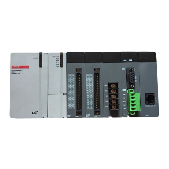
Chapter 2 Product Specification 2.3 Structure and Features ◀ LED Display ◀ Connectors [Table 2.3.1] LED Display Specification LED Display LED Status Description Normal A/S inspection required Blink Normal On/Off A/S inspection required High speed link communication in service Link trouble error, or any one of the set-up communication Blink block fails to perform normal service High speed link communication service has stopped... -
Page 18: Cable Specification
Chapter 2 Product Specification 2.4 Cable Specification 2.4.1 Electric Cable (LS Cable) [Table 2.4.1] Electric Cable Specifications LIREV-AMESB Classification Structure 2 *0.64mm 22AWG Manufacturer LS Cable Conducto Cable Type Twisted pair, shielded 59Ω/㎞ Conductor Resistance Insulator (room temperature) Withstand Voltage (DC) 500 V/Min (room temperature) Earth... -
Page 19: Terminating Resistor
Chapter 2 Product Specification 2.4.3 Terminating Resistor Install terminating resistor at both ends of line. Install terminating resistors to TRX2+ and TRX2-. XGL-FMEA Joint Cable 110,1/2W Terminating Resistor:... -
Page 20: Chapter 3 Product Installation And Test-Run
Chapter 3 Installation and Test-Run Chapter 3 Product Installation and Test-Run 3.1 Cautions for Handling 3.1.1 Cautions for Handling Following basic specifications apply to the construction of Fnet I/F module systems. Check the system requirements and select appropriate communication module. Select the cable for the communication module (make sure to use standard cable). -
Page 21: Product Setting For Operation
Chapter 3 Installation and Test-Run 3.2 Product Setting for Operation This section describes the installation and operation of the product. When the product has been installed, configure and set the system with the following procedures. Procedure Mount the Fnet I/F module on the base. →... -
Page 22: Registration Of Communication Module
Chapter 3 Installation and Test-Run 3.3 Registration of Communication Module To use an XGT Fnet I/F module, set up communication parameters with XG-PD, and register the module on the XG-PD for system setting-up of the XGT Fnet I/F module. The registration procedures of the XGT Fnet I/F XGnet I/F modules are as follows, according to the online or off-line status. -
Page 23: Online Registration
Chapter 3 Installation and Test-Run 3.3.2 Online Registration To register communication module using XG-PD in online status, conduct the steps No. 1 and 2 of the off- line registration for XGT FnetI/F module, and conduct following steps. Enter project name in the project name field, select PLC series and CPU type If unable to connect, check the connectivity with the PLC, select Online ... - Page 24 Chapter 3 Installation and Test-Run The list of the communication modules installed in the product is created in the project window.
-
Page 25: Reading Parameters From Plc
Chapter 3 Installation and Test-Run 3.3.3 Reading Parameters from PLC The default setting values and high speed link setting values saved in PLC can be loaded with following procedures. From file menu, select Open from PLC. Set up connection method and step, click Connect or OK. Enter the project name and folder path for save, click Confirm. - Page 26 Chapter 3 Installation and Test-Run You can view the default setting and high speed link setting values stored in the PLC.
-
Page 27: Module Setting Procedure
Chapter 3 Installation and Test-Run 3.3.4 Module Setting Procedure Set up the XGT Fnet I/F module as follows for operation. Procedure (1) Direct input in project window Select Online Project Window the base to be installed with the module, click mouse right button to set up the type and position of the XGT Fnet I/F module. -
Page 28: Relation Between The Menu Bar And Shortcut Icons Of Xg-Pd
Chapter 3 Installation and Test-Run 3.3.5 Relation between the Menu Bar and Shortcut Icons of XG-PD The relation between the menu bar and shortcut icons of the XG-PD are as follows. Menu bar Menu Icon Description New File Create a new file Open Open a saved file Open from PLC... - Page 29 Chapter 3 Installation and Test-Run Menu bar Menu Icon Description Register EDS File Register an EDS file Delete an EDS file Delete EDS File (Delete EDS of the module active in EIP configuration window) View EDS file in memo (Information of the module active in View EDS File EIP configuration window) User Defined...
-
Page 30: Chapter 4 System Configuration
Chapter 4 System Configuration Chapter 4 System Configuration 4.1 Network System Configuration Systems using Fnet I/F module can be configured with the XGT Fnet I/F modules only or with XGT Fnet I/F module and GM/MK Fnet I/F module. Therefore, additional configuration can be implemented to the existing systems consisted with GM/MK Fnet I/F modules. - Page 31 Chapter 4 System Configuration XGL-FMEA XGL-FMEA XGL-FMEA G0L-FREB Fnet system G6L-FUEA G4L-FUEA G3L-FUEA Optical cable G0L-FOEA G0L-FOEA G4L-FUEA G4L-FUEA [Fig. 4.1.3] System with existing GM/MK Fnet added with XGT Fnet...
-
Page 32: Chapter 5 High Speed Link Service
Chapter 5 High Speed Link Service Chapter 5 High Speed Link Service 5.1 Outline of High Speed Link High speed link is a communication method between XGT PLC communication modules, which can communicate data periodically by high speed link parameter setting. It is a data communication service where the user can set up the communication parameters for the data size, intervals, area and storage area of communication using XG-PD. -
Page 33: Using Xg-Pd
Chapter 5 High Speed Link Service 5.2 Using XG-PD For using the Fnet I/F module, the XG-PD has to be set up in following procedures. Run XG-PD 1) File -> New File Create a new XG-PD file for the Fnet I/F module (1) Project Name A) Enter Project name (2) Select PLC Series... - Page 34 Chapter 5 High Speed Link Service 4) Set up HS link communication module in the project window A) Set up communication module: Fnet - Module type, base, slot B) Set up communication intervals C) Set up emergency output data - CPU module error, CPU module stop 5) Set up HSL Block in Project Window...
- Page 35 Chapter 5 High Speed Link Service 7) Enable Link Allow communication for the installed Fnet I/F module Select “Online – Enable Link” and the pertinent HS Link, and click OK.
- Page 36 Chapter 5 High Speed Link Service * Enable Link through flag It describes “Enable Link” method through flag. The following XG5000 version, CPU OS version is needed. Item Version XG5000 V3.61 or above XGR CPU V1.91 or above XGI CPU V3.4 or above XGK CPU V3.7 or above...
- Page 37 Chapter 5 High Speed Link Service Flag Data type Device Description _HS10_REQ F10309 HS link 10 enable/disable request _HS11_REQ F1030A HS link 11 enable/disable request _HS12_REQ F1030B HS link 12 enable/disable request _HS1_REQ_NUM F10310 HS link 1 enable/disable setting _HS2_REQ_NUM F10311 HS link 2 enable/disable setting _HS3_REQ_NUM...
-
Page 38: Setting-Up High Speed Link
Chapter 5 High Speed Link Service 5.3 Setting-up High Speed Link When the XG-PD is loaded, the screen below will appear. [Initial Window] The parameters which can be set up in XG-PD are as follows. Standard Setting High Speed Link Window Window... - Page 39 Chapter 5 High Speed Link Service The window used by Fnet I/F module is high speed link window. Up to 12 high speed links can be used. Each Fnet I/F module can make use of one high speed link. Using high speed link window Select the high speed link window where the user can set up following parameters.
- Page 40 Chapter 5 High Speed Link Service Communication module setting parameter Communication module parameters can be set up as follows. Parameter Window Item Description Module Type Select Fnet Comm. Setting range: 0 ~ 7 Base No. Module Range may vary by CPU module Setting Setting range: 0 ~ 11 Slot No.
- Page 41 Chapter 5 High Speed Link Service High speed link block setting parameter Following parameters can be set up in high speed link block. Item Description Station Type Fix to Local Transmission: outbound data flow Mode reception: inbound data flow Station No. Internal/External station No.
- Page 42 Chapter 5 High Speed Link Service Edit tools for high speed link block The edit tools and their use are presented in the table below. Item Description Undo Cancel input during parameter edit Redo Do the previous input again Cut off an object Copy Copy and object Paste...
-
Page 43: Read And Write High Speed Link
Chapter 5 High Speed Link Service 5.4 Read and Write High Speed Link “Online -> Connect -> Online -> Read/Write Parameter” is used to read or write high speed link parameters. The window is described below. Window Configuration Description 1) For Fnet I/F module, up to 12 high speed links can be set up. - Max, 12 are available including other communication module using high speed link. -
Page 44: System Diagnosis
Chapter 5 High Speed Link Service 5.5 System Diagnosis System diagnosis provides the comprehensive information on the system consists of Fnet I/F module. The system diagnosis window and its content are presented below. Menu Bar System Diagnosis Window Select the module with mouse and click it with mouse right button. The menu for system diagnosis is as follows. - Page 45 Chapter 5 High Speed Link Service High speed link (HSL) Screen and configuration Standard Base No. No. of the base mounted with the product connected with HSL Info. Slot No. No. of the slot mounted with the product connected with HSL 1: after power On, HSL parameter operates normally at initial phase Run Link Total HS...
- Page 46 Chapter 5 High Speed Link Service Auto Scan Window Configuration and Description The communication characteristics of the slave module configured in HSL is represented with product structural diagram 1) During normal communication: the station No. is displayed 2) Communication stopped: no station is shown 5-15...
-
Page 47: High Speed Link (Hsl) Information
Chapter 5 High Speed Link Service 5.6 High Speed Link (HSL) Information HSL communicates data between stations. The information of its normal operation-or-not is provided by flag on station basis or for all the stations. This information can be used to check the reliability of communication data or cause of error of the system. -
Page 48: Chapter 6 Sample Program
Chapter 6 Sample Program Chapter 6 Sample Program 6.1 Application Sample in XGK-CPU In this section, high speed link parameter setting method is provided with sample programs for an XGT Fnet system as shown below Here, the high speed link parameter settings are in accordance with the XGK #1. Fnet Station no.: 7 Fnet Station no.: 4 Fnet Station no.: 0... - Page 49 Chapter 6 Sample Program In the exemplary system, the high speed link parameter can be set as follows.
-
Page 50: Example Using Xgi-Cpu
Chapter 6 Sample Program 6.2 Example using XGI-CPU In this section, high speed link parameter setting method is provided with sample programs for an XGT Fnet system as shown below Here, the high speed link parameter settings are in accordance with the XGI #1. With the Fnet system below, high speed link parameter setting method is described as below. - Page 51 Chapter 6 Sample Program The result of parameter setting in the XG-PD is as follows.
-
Page 52: Chapter 7 Max. Guarantee Time For Data Communication
(add 2 instead of 1 as safety factor). E.g.) In an XGT series with 20 transmission blocks, the 3 tokens are required for data transmission. 4) Max. Guarantee Time for Inter-Station Data Communication Transmission PLC delay time + reception PLC delay time + transmission time If the No. -
Page 53: Calculation Of The Max. Guarantee Time For Data Communication Between Stations
Stations The case below is based on; an XGT series having the station numbers and transmission blocks as presented below; program scan of each station is 10msec, and; the time required for the station 4 transmitting data to the station 1. -
Page 54: Master Switching Time
Chapter 7 Max. Guarantee Time for Data Communication 7.3 Master Switching Time Any station in the FNET can be a master station through competition for master. The station then acts as the LAS station and other stations act as slave stations. If the master is disabled for any reason, other stations compete for the mastership. This takes a little time which can be calculated as follows. -
Page 55: Appendix
APPENDIX APPENDIX А.1 Terms and Definitions Self station The Fnet I/F modules currently connected with XG-PD. Usually, of the Fnet I/F modules installed in the current PLC, those which are connected to XG-PD and monitored and diagnosed. Destination station Other F-net I/F modules connected with the self station via Fnet. Usually refers to the Fnet I/F modules installed in other PLCs, the Fnet I/F modules installed in other slots of the current PLC may in this category. - Page 56 APPENDIX CRC (Cyclic Redundancy Check) A method of error detection widely used in synchronous communication. Terminating Resistor The resistor used for impedance matching between the transmitter and receiver on a physical layer. The terminating resistor of Fnet is 110Ω,1/2 W HS (High Speed) Link A communication method applicable for Fnet communication modules only.
- Page 57 APPENDIX А.2 Flag Alarm А.2.1 HIGH SPEED LINK Flag [Table A.2.1] Communication flag according to HSL No. (HSL No. 1 ~ 12) Key word Type Description Detail Explanation All the stations are working normally according to the parameters set up in the HSL.
- Page 58 APPENDIX Note HSL No. L Area Address Remark L000500~L00099F Comparing to the HSL #1 of the [Table 1], the flag address No. of other HSL station No. can be calculated with the formula below. L001000~L00149F L001500~L00199F L Area Address No. = L000000 + 500 x (HSL No. – 1) L002000~L00249F L002500~L00299F L003000~L00349F...
-
Page 59: Appendix 3 Dimensions
APPENDIX A.3 Dimensions Unit: mm... - Page 60 LSIS provides an 18-month warranty starting from the date of production. 2. Range of warranty For problems within the terms of the warranty, LSIS will replace the entire PLC or repair the defective parts free of charge except for the following cases.
- Page 61 2 Zhongshan Liu Road.Guangzhou.P.R China Tel : 86-20-8328-6754/Fax : 86-20-8326-6287 e-mail : chenxs@lsis.com.cn ※ LSIS constantly endeavors to improve its product so that 2011. 5 information in this manual is subject to change without notice. ⓒ LSIS Co., Ltd 2011 All Rights Reserved.
Need help?
Do you have a question about the XGT Series and is the answer not in the manual?
Questions and answers