LSIS XGT Series User Manual
Bacnet/ip i/f module
Hide thumbs
Also See for XGT Series:
- User manual (909 pages) ,
- Manual (48 pages) ,
- User manual (99 pages)
Table of Contents
Advertisement
Quick Links
Right choice for ultimate yield
LSIS strives to maximize customers' profit in gratitude of choosing us for your partner.
Programmable Logic Controller
XGT Series
Read this manual carefully before
installing, wiring, operating, servicing
or inspecting this equipment.
Keep this manual within easy reach
for quick reference.
BACnet/IP I/F Module
User's Manual
XGL-BIPT
http://www.lsis.com
Advertisement
Table of Contents

Related Manuals for LSIS XGT Series


Summary of Contents for LSIS XGT Series
- Page 1 Right choice for ultimate yield LSIS strives to maximize customers' profit in gratitude of choosing us for your partner. Programmable Logic Controller BACnet/IP I/F Module XGT Series User’s Manual XGL-BIPT Read this manual carefully before installing, wiring, operating, servicing or inspecting this equipment.
- Page 2 Safety Instructions Before using the product … For your safety and effective operation, please read the safety instructions thoroughly before using the product. ► Safety Instructions should always be observed in order to prevent accident or risk with the safe and proper use the product. ►...
- Page 3 Safety Instructions Safety Instructions for design process Warning Please install a protection circuit on the exterior of PLC so that the whole system may operate safely regardless of failures from external power or PLC. Any abnormal output or operation from PLC may cause serious problems to safety in whole system.
- Page 4 Safety Instructions Safety Instructions for design process Caution I/O signal or communication line shall be wired at least 100mm away from a high-voltage cable or power line. Fail to follow this instruction may cause malfunctions from noise Safety Instructions on installation process Caution ...
- Page 5 Safety Instructions Safety Instructions for wiring process Warning Prior to wiring works, make sure that every power is turned off. If not, electric shock or damage on the product may be caused. After wiring process is done, make sure that terminal covers are ...
- Page 6 Safety Instructions Safety Instructions for test-operation and maintenance Warning Don’t touch the terminal when powered. Electric shock or abnormal operation may occur. Prior to cleaning or tightening the terminal screws, let all the external power off including PLC power. If not, electric shock or abnormal operation may occur.
- Page 7 Safety Instructions Safety Instructions for waste disposal Caution Product or battery waste shall be processed as industrial waste. The waste may discharge toxic materials or explode itself.
- Page 8 Revision History Version Data Remark Page V 1.0 ’14.05 First Edition V 1.1 ’15.01 XG5000 V4.0 UI Updated ※ The number of User’s manual is indicated right part of the back cover. Copyright ⓒ 2014 LSIS Co., Ltd All Rights Reserved.
- Page 9 User’s Manual. The User’s Manual describes the product. If necessary, you may refer to the following description and order accordingly. In addition, you may connect our website (http://www.lsis.biz/) and download the information as a PDF file. Relevant User’s Manuals Manual...
-
Page 10: Table Of Contents
Contents ◎ Contents ◎ Chapter 1 Overview 1.1 Overview------------------------------------------------------------------------------------------------------------------------------------------------- 1-1 1.2 Features-------------------------------------------------------------------------------------------------------------------------------------------- 1-2 1.3 Product Configuration----------------------------------------------------------------------------------------------------------------------------------- 1-3 1.3.1 Module name indication----------------------------------------------------------------------------------------------------------------- 1-3 1.3.2 Number of units installed by CPU------------------------------------------------------------------------------------------------------- 1-3 1.4 Software to use the product-------------------------------------------------------------------------------------------------------------------- 1-4 1.4.1 Software check point------------------------------------------------------------------------------------------------------------------- 1-4 1.4.2 XG5000 --------------------------------------------------------------------------------------------------------------------------------- 1-4 1.4.3 Check of version----------------------------------------------------------------------------------------------------------------------------- 1-5 Chapter 2 Product Specifications... - Page 11 Contents 5.3.1 XG5000 installation ---------------------------------------------------------------------------------------------------------------------------- 5-6 5.3.2 USB device driver installation(Installation in windows XP)------------------------------------------------------------------------- 5-9 5.3.3 Confirmation of installed USB device driver ------------------------------------------------------------------------------------------ 5-12 5.4 Communication Module Registration ----------------------------------------------------------------------------------------------------------- 5-18 5.4.1 Off-line registration of BACnet I/F module ----------------------------------------------------------------------------------------- 5-18 5.4.2 Online registration of BACnet I/F module ---------------------------------------------------------------------------------------- 5-20 5.4.3 How to read the parameter saved in the PLC --------------------------------------------------------------------------------------- 5-22 5.4.4 BACnet/IP I/F Module setting method -------------------------------------------------------------------------------------------------- 5-23 5.4.5 Menu bar and shortcut of XG5000 ------------------------------------------------------------------------------------------------------ 5-24...
-
Page 12: Chapter 1 Overview
Chapter1 Overview Chapter 1 Overview 1.1 Overview This User Manual provides guidance for BACnet/IP I/F Module (hereafter referred to as “BIPT Module” in this manual), a XGT PLC System network. BACnet refers to a standard communication protocol named ANSI/ASHRAE Standard 135- 1995, jointly employed and supported by American National Standard Institute (ANSI) and American Society of Heating, Refrigerating and Air-conditioning Engineers (ASHRAE). -
Page 13: Features
Chapter1 Overview 1.2 Features Features of XGT BACnet/IP I/F Module are provided below. (1) Device Profile: B-ASC + Client Function Device Profile B-ASC + Client DS-RP-A,B DS-RPM-A,B Data Sharing DS-WP-A,B DS-WPM-A,B DM-DDB-B Device & Network Management DM-DOB-B DM-DCC-A,B * Reference 5.1.1 XGL-BIPT Profile and BACnet Interoperability Building Blocks (BIBB’s) (2) Compatibility: compatible with ANSI/ASHRAE 135-1995 (3) Provides 100BASE-TX media, and supports 100Mbps/Full Duplex. -
Page 14: Product Configuration
Chapter1 Overview 1.3 Product Configuration 1.3.1 Module name indication This section describes product configuration of XGT BACnet/IP I/F module Model name Content Remarks XGL-BIPT Electrical 2-port BACnet/IP module Category 5 or higher 1.3.2 Number of units installed by CPU Up to 24 XGT BACnet/IP I/F modules can be installed on either main base or expanded base. Please install the modules on the main base to gain their maximum performance. -
Page 15: Software To Use The Product
CD-ROM for the programs. Internet Web Address : http://www.lsis.com 2) You can use RS-232C port and USB of the CPU module to program XG5000. Please see the XGT catalogue product list for the type name of the cable used (USB-301A, K1C-050A). -
Page 16: Check Of Version
Chapter1 Overview 1.4.3 Check of version Before using XGT BACnet/IP I/F module, please identify the version of the module. Identification through XG5000 You can read the information of a communication module by directly connecting to the module on-line. If interface with CPU is normal, the information shown in the figure can be obtained. (1) Run XG5000. -
Page 17: Chapter 2 Product Specifications
Chapter 2 Product Specifications Chapter 2 Product Specifications General Specifications General specifications of XGT series are as shown in Table 2.1. Items Specification Reference 0 ~ 55 °C Ambient T emp. −25 ~ +70 °C Storage T emp. Ambient humidity... -
Page 18: Performance Specifications
Chapter 2 Product Specifications 2.2 Performance Specifications The following describes system configuration specifications according to the media of BACnet/IP I/F module. Please refer to the table below for system configuration. Communication load is classified load by media interrupt per second at media of BACnet I/F module and transmission load (by Link I/F) that send to the BACnet I/F module from CPU module. -
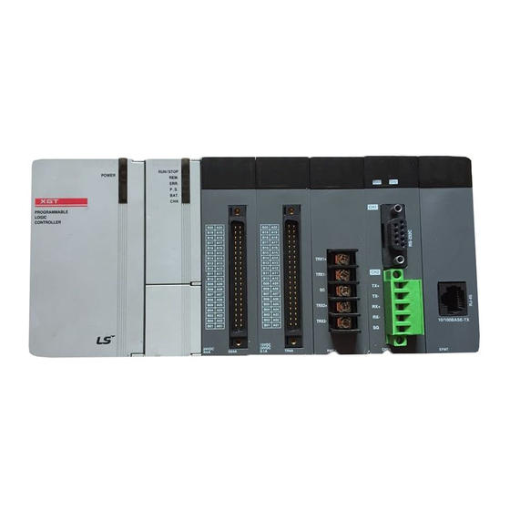
Page 19: Designations Of Parts
Chapter 2 Product Specifications 2.3 Designations of Parts Names of each part of the PLC are as follows. LED Display Station setting switch Ethernet Connector (CH 1) LOG Switch Ethernet Connector (CH 2) [Figure 2.3] Front view of PLC module ▶... - Page 20 Chapter 2 Product Specifications ▶ Log switch In case there is a need to read log in communication module and store the log, it is stored from the memory area to flash area by pressing it for more than one second. The memory area log is removed when power is turned on again, and flash area log is maintained even when power is turned on again.
-
Page 21: Cable Specifications
Chapter 2 Product Specifications 2.4 Cable Specifications 2.4.1 UTP cable UTP cable is classified into 3 types based on the following criteria. ▶ Shield: classified into 3 (UTP, FTP, STP) ▶ Frequency band used: classified into 7 (Cat. 1~7) ▶ Classification by flame retardant grade: 4 types(CMX, CM, CMR, CMP) 1) Type of cables (shield) Classification Details... - Page 22 Chapter 2 Product Specifications 2) Classification based on frequency used Frequency used Transmission Speed Classification Purpose (MHz) (Mbps) Category 1 Phonetic Frequency Phone network (2-Pair) Category 2 Multi-Pair communication cable Category 3 Phone network + Computer network 1) Computer network transmission Category 4 speed Up 2) Low-loss communication cable...
- Page 23 Chapter 2 Product Specifications 4) Example (CTP-LAN5) of Category 5 twisted-pair cable (UTP) Item Unit Value Ω/km Conductor resistance(Max) 93.5 MΩ·km Insulation resistance(Min) 2,500 Voltage endurance V/min AC 500 Ω(1~100MHz) Characteristic impedance 100 ± 15 10MHz dB/100m Attenuation 16MHz or less 20MHz 10MHz dB/100m...
-
Page 24: Chapter 3 Installation And Test Operation
Chapter 3 Installation and Test Operation Chapter 3 Installation and Test Operation 3.1 Installation Environment This product is of high reliance regardless of installation environment. However, for the sake of reliance and stability of the system, please pay attention to those precautions described below. Environmental Conditions (a) To be installed on the control panel waterproof and dustproof. -
Page 25: Precautions For Handling
Chapter 3 Installation and Test Opertation 3.2 Precaution for Handling The system configuration with RAPIEnet I/F module shall be performed under the following precautions. (1) Don’t let it dropped or shocked hard. (2) Don’t remove PCB from the case. It will cause abnormal operation. (3) Don’t let any foreign materials including wiring waste inside the top of the module when wiring. -
Page 26: Operation Sequence
Chapter 3 Installation and Test Operation 3.3 Operation Sequence The sequence of the product from installation to operation will be described below. After the product installation is complete, install and configure the system to be operated as specified in the following sequence. START Check the functions and specification to be used. -
Page 27: I/O Assignment And Device Information
Chapter 3 Installation and Test Opertation 3.4 I/O Assignment and Device Information 3.4.1 I/O assignment (1) Using XGK CPU (a) Configuration method of basic system The features of Basic system consisted by connecting the main base and expanded base by a cable are as follows. The number of steges of expanded base is limited according to the CPU type and the allocation method of I/O No. - Page 28 Chapter 3 Installation and Test Operation (d) Maximum configuration 1) Max. configuration of basic system (fixed point) Slot no.: P0000 P0040 P0080 P0120 P0160 P0200 P0240 P0280 System Configuration Main base Power Example 1 (base no.:0) P003F P007F P011F P015F P019F P023F P027F...
- Page 29 Chapter 3 Installation and Test Opertation 2) Max. configuration of basic system (variable point) Slot no.: P0000 P0010 P0020 P0030 P0040 P0050 P0060 P0070 System Main base Power Configuration (base no.:0) P000F P001F P002F P003F P004F P005F P006F P007F Example 2 Expanded cable Slot no.: - I/O variable point...
- Page 30 Chapter 3 Installation and Test Operation (2) Using XGI CPU (a) Basic system configuration Classification XGI-CPUH, CPUU, CPUU/D XGI-CPUS XGI-CPUE Max. extension stage 7 stages 3 stages 1 stage Max. number of I/O module extension 96 modules 48 modules 24 modules mounted Max.
- Page 31 Chapter 3 Installation and Test Opertation (b) Max. system configuration Slot no.: 0.0.0 0.1.0 0.2.0 0.3.0 0.4.0 0.5.0 0.6.0 0.7.0 Basi c base System Configuration Power Example 2 (Base no.:0) 0.0.16 0.1.15 0.2.15 0.3.15 0.4.15 0.5.15 0.6.15 0.7.15 - XGI-CPUU - 8 slot base Expanded cable - When installing...
-
Page 32: Installation Of The Product
Chapter 3 Installation and Test Operation 3.5 Installation of the Product 3.5.1 XGL-BIPT installation Twist pair cable RJ45 Connector [Figure 3.6.1] 100BASE-TX Installation The maximum length of 100BASE-TX segment is 100m (distance between modules) Straight cables or crass cables are used. You can reduce the time required for link connection by using cross cables to connect the communication modules. - Page 33 Chapter 3 Installation and Test Opertation How to install UTP (1) For reliable 100Mbps signal transmission using UTP cable, patch cord, line cord, patch panel and DVO (Data Voice Outlet) should all have characteristics that satisfy EIA/TIA-568A, which is a category 5 spec. (2) In a cross-connect system, the length of patch cord must not exceed 7 meters.
-
Page 34: Precaution
Chapter 3 Installation and Test Operation 3.6 Precaution 3.6.1 Precautions for system configuration When using P2P services including the module in this manual, each station must have a different IP address from all the other stations. Please use communication cables with designated specifications. Using other cables may cause severe communication problems. -
Page 35: Chapter 4 System Configuration
Chapter 4 System Configuration Chapter 4 System Configuration BACnet/IP I/F module can be installed without regard to XGT CPU module. The maximum number of units installed is 24, which includes basic base and expanded base (XGR system is restricted by a main base). Among them, 8 units can be used as P2P service, and all 24 units are available when used as a server. -
Page 36: Chapter5 Communication Parameter
Chapter 5 Communication parameter Chapter5 Communication Parameter 5.1 Overview BACnet’s communication method is based on the client-server model. A BACnet device consists of more than one object specified by ASHRAE, with each object having its properties including the ID and name. With such services as ReadProperty and WriteProperty, you can read property values of a certain object or change them. -
Page 37: Id Allocation Of Input / Output Modules
Chapter 5 Communication parameter 5.2 ID Allocation of Input / Output Modules BACnet objects provided by BIPT communication module are Analog Input, Analog Output, Binary Input, and Binary Output. Analog Input object corresponds to Analog Input Module, Analog Output object corresponds to Analog Output Module, Binary Input object corresponds to Digital Input Module, and Binary Output Object corresponds to Digital Output Module. -
Page 38: Object Id Allocation Method Of Input / Output Modules
Chapter 5 Communication parameter 5.2.2 Object ID allocation method of input / output modules In order to control input / output modules through BACnet protocol, ID’s should be allocated to BACnet objects corresponding to input / output modules. 32 ID’s per slot are allocated to analog input modules or output modules, and 64 ID’s per slot are allocated to digital input modules or output modules. - Page 39 Chapter 5 Communication parameter Analog Output Module: (1) Module Type : all output modules (2) Object ID’s of analog output module corresponding to the number of channels are sequentially mapped, starting from the object ID that is the starting object ID + 3. The figure below shows a case with 8 channels. As shown in the figure below, the data corresponding to a channel may be accessed through object ID.
- Page 40 Chapter 5 Communication parameter Digital Input / Output Module (1) Model Type: all digital input or output modules (2) As for digital input module or output module, ID’s corresponding to the number of contact points are sequentially mapped starting from the starting object ID allocated to the relevant slot. The figure below shows a case with 8 channels.
-
Page 41: Installation And Execution Of Software
Chapter 5 Communication parameter 5.3 Installation and Execution of Software In order to user the XG5000 software, you need to install the XG5000. The system specifications required for the execution are as follows. (1) Personal Computer and Memory - A set of computer with Pentium and higher CPU and 128MB and more memory. (2) COM Port - RS-232C serial port or USB port is necessary. - Page 42 Chapter 5 Communication parameter (6) Select a folder to install XG5000 into. If you want to change the folder, click Browse… button and make or select a new folder. XG5000 needs about 30M Bytes of installation space in hard disk, which will ask you to select a disk with enough capacity.
- Page 43 Chapter 5 Communication parameter (9) Installation will be started as shown below. (10) Wait a second for the installation to be complete.
-
Page 44: Usb Device Driver Installation(Installation In Windows Xp)
Chapter 5 Communication parameter 5.3.2 USB device driver installation(Installation in windows XP) (1) Ensure that Drivers folder is created in the folder where XG5000 is installed, and there are 2 driver files of GmUSBD.sys and GmUSBD.inf in the Drivers folder. If there is no folder or driver file, reinstall XG5000. (2) Turn PLC Power on and connect USB connector with PC. - Page 45 Chapter 5 Communication parameter (5) Click [Browse] button. On Browse Folder Dialog Box, select Drivers’ folder where XG5000 is installed. (6) Click [OK] button. Then, a computer starts searching for the driver files in the selected folder. (7) If the computer found the most suitable device driver, you will be asked to decide to install the selected device driver. Since USB device driver operated stably based on Windows OS, you may click [Continue Anyway] button.
- Page 46 Chapter 5 Communication parameter (8) If the device driver has been installed completely, the Installation Complete Dialog Box will be displayed as follows. Click [Finish] button to end the installation of the driver. Note If XG5000 is installed on Windows XP for the first time, It needs USB device driver installation as an additional step. USB device driver shall be also installed as described below.
-
Page 47: Confirmation Of Installed Usb Device Driver
(a) Normal case The USB device driver for XGT PLC has been installed successfully, if the list [LSIS XG Series] appears with the figure under [Universal Serial Bus Controller]. 5-12... - Page 48 Chapter 5 Communication parameter (b) Abnormal case The device driver has not been installed successfully, if the following figure is displayed. If the USB driver for XGT PLC is not installed successfully, reinstall the USB driver for XGT PLC in the following steps. [Steps] (1) On the device driver with the icon with an exclamation mark, click the right button of the mouse.
- Page 49 Chapter 5 Communication parameter (2) H/W Update Wizard Dialog Box will appear. Select the option “Installation from a list or specific location (Advanced)” and click [Next]. The next sequence is manually the same as in Installation of Device Driver. If the USB driver for XGT PLC is not installed successfully, reinstall the USB driver for XGT PLC in the following steps [Steps] (1) If the device driver has been installed incorrectly or in error, execute H/W Update Wizard.
- Page 50 Chapter 5 Communication parameter (2) On search and installation options, select [Don’t Search. I will choose the driver to install.] and click [Next] (3) Click [Have Disk…] on the Dialog Box below 5-15...
- Page 51 Chapter 5 Communication parameter (4) If Installation Dialog Box is displayed on the disk, click [Browse] button. (5) From the Browse File Dialog Box, move to the folder XG5000 is installed in. Select drivers folder to display GmUSBD.inf file. With this file selected, click [Open] button. (6) On the item of ‘Copy manufacturer’s files from’, a directory with the file of the device driver will be displayed.
- Page 52 Chapter 5 Communication parameter (7) On ‘Show compatible hardware’ list of the device driver Select Dialog Box, select “LSIS XGSeries” driver and then click [Next] button (8) Hardware Installation Dialog Box will appear. Click [Continue Anyway] to go on with the installation (9) Completing the Hardware Update Dialog Box will appear.
-
Page 53: Communication Module Registration
Chapter 5 Communication parameter 5.4 Communication Module Registration In order to use BACnet I/F module, communication parameters shall be specified in XG5000. And for system setting of BACnet I/F module positioned at an optional place, its applicable module shall be registered in XG5000. How to register the optionally positioned BACnet I/F module depends on On/Off line status as described below. - Page 54 Chapter 5 Communication parameter b) Click “Add Module” in “Select communication module” window. c) Set the communication module type, base number and slot number in “Communication Modlule Settings” window. Screen that BACnet I/F module mounted in slot3 of base 0 is as follows. 5-19...
-
Page 55: Online Registration Of Bacnet I/F Module
Chapter 5 Communication parameter 5.4.2 Online registration of BACnet I/F module Step (1), (2) of off-line registration is same and the next step is as follows. (1) Input the project name, file location and PLC type the user is using. (2) If connection fails, check the connection status. - Page 56 Chapter 5 Communication parameter (6) The list of the mounted communication module shows in the Project window. 5-21...
-
Page 57: How To Read The Parameter Saved In The Plc
Chapter 5 Communication parameter 5.4.3 How to read the parameter saved in the PLC To read the parameter saved in the PLC, follow the below sequence. (1) Select the ‘Open from PLC’. (2) The user can check the setting value of standard settings and P2P saved in the PLC. 5-22... - Page 58 Chapter 5 Communication parameter 5.4.4 Module setting method To use BACnet/IP I/F module, set as the following steps 1) Execution sequence (1) Direct input in project window [Online] – [Project Window], Double-clicks the slot number which is mounted BACnet/IP I/F module. Communication module setting window is appeared on the main window.
-
Page 59: Menu Bar And Shortcut Of Xg5000
Chapter 5 Communication parameter 5.4.5 Menu bar and shortcut of XG5000 The following is menu bar and short cut of XG5000. (The other menu, please refer to the XG5000 User’s manual). Menu bar Menu Icon Description New Project Create a new project. Open Project Open the existing project. - Page 60 Close all windows belonging to XG5000. Reset Window Layout - Reset the default layout of the project. Help Open the help for each item LSIS Home Page Connect to LSIS Home Page via the Internet. Help About XG5000 Shows XG5000 information. 5-25...
-
Page 61: Chapter 6 P2P Service
Chapter 6 P2P service Chapter 6 P2P Service 6.1 Overview A BACnet device consists of more than one object, which has a number of properties. The read / write services of data sharing defined by the BACnet specification refers to the function of reading and writing these properties. In BACnet, communication is provided based on the client-server model, and corresponds to the company’s P2P service. -
Page 62: Service Settings
Chapter 6 P2P service 6.2 Service Settings 6.2.1 Module settings After setting communication module and basic parameters using XG5000, you can start configuration by dragging the EDS file of the country that you want to communicate with. Communication Module Setting and Basic Parameter Setting Right click on “Unspecified Network”... - Page 63 Chapter 6 P2P service After registration, you should configure the channel for the BACnet device to connect with. The channel information required is the IP address and device ID of the relevant device. You can also add descriptions. [Figure 4] P2P Channel Information Once P2P channel information is set, you can begin block editing.
- Page 64 Chapter 6 P2P service In order to directly access (read/write) the CPU module memory device of BIPT server module, objects for exclusive use by LSIS have been added. Object Code Remarks LSIS-P-Device P device area LSIS-M-Device M device area...
- Page 65 Chapter 6 P2P service Read Parameter Choose ‘parameter read’ on-line. Here, you can read the configured parameter by checking the relevant parameter and then clicking the ‘Confirm’ button. [Figure 7] Read Parameter P2P Information As P2P information is provided to users using user keywords, you can use the information in the program. P2P Flag Types [Figure 8] P2P Flag Information...
-
Page 66: Start Of The Operation
Chapter 6 P2P service 6.3 Start of the Operation 6.3.1 XG5000 settings Connection settings (1) Select Online → Connection Settings or click the ( ) icon. (2) Select the connection option appropriate for the user environment, and click ‘Connect.’ [Figure 9] Connection Settings Read I/O Information Select Online →... - Page 67 Chapter 6 P2P service [Figure 10] Link Enable Operation Confirmation. (1) Select Online → System Diagnosis or click the ( ) icon. (2) Click the relevant module, and right click on frame monitoring or service statuses to see if communication is being performed normally.
-
Page 68: Status Information By Service
Chapter 6 P2P service 6.4 Status Information by Service Using XG5000, you can view status information of each service, including P2P-related data or server-related data. 6.4.1 System diagnosis to P2P service Select XG5000 → ‘Connect’ → ‘Online’ → ‘Communication module setting’ → ‘System Diagnosis.’ [Figure 12] System Diagnosis Screen Put the mouse cursor on XGL-BIPT and right click on the information you want, then you will be able to view the information as shown below. - Page 69 Chapter 6 P2P service [Figure 14] System Diagnosis – Server service...
-
Page 70: Chapter 7 Diagnosis
Chapter 7 Diagnosis Chapter 7 Diagnosis This chapter explains how to verify the status of systems, modules and networks, and how to download the O/S. System composition and status of BACnet I/F module can be verified following the procedure below. 7.1 System Diagnosis This method is used to verify the status of BACnet I/F module and system. - Page 71 Chapter7 Diagnosis [Figure 7.1.3] System Diagnosis Screen for Augmenting base [Figure 7.1.4] Module Information Window for Augmenting base...
-
Page 72: Communication Module Information
Chapter 7 Diagnosis 7.2 Communication Module Information This screen shows basic information of BACnet I/F module. On the system diagnosis screen, right-click on the BACnet I/F module of which communication module information you want to view. Then select ‘Communication Module Information’ to open the communication module information screen as shown in [Figure 7.2.1]. -
Page 73: Status By Service
Chapter7 Diagnosis 7.3 Status by Service This screen shows service status of BACnet I/F module. It shows P2P service and server information. [Figure 7.3.1] Status Screen for each Service... - Page 74 Chapter 7 Diagnosis The tables below describe the items shown in P2P service information. Item Contents Block number Displays index number of the block being serviced Channel number Displays channel number of the block being serviced Block status Displays status of the block being serviced Service status Displays the number of services per second of the block being serviced Service count...
-
Page 75: Media Information
Chapter7 Diagnosis 7.4 Media Information Select ‘Media Information’ from the diagnosis information of XG5000: it will show the information on transmitted/received frames in such categories as service, media, packet type, etc. [Figure 7.4.1] Media Information Screen... -
Page 76: Ping Test
Chapter 7 Diagnosis 7.5 Ping Test You can perform ping test at the selected module. You can configure the IP Address, number of configurations and timeouts. The result will be shown on a message window. [Figure 7.5.1] Ping Test... -
Page 77: Auto Scan
Chapter7 Diagnosis 7.6 Auto Scan This screen shows the information of BACnet devices connected to BACnet network system connected with BACnet module. You can scan within a certain range defined using Who-is and Who-has of BACnet 7.6.1 Who-is Service This shows IP address and device ID of connected BACnet devices. You can configure the range of Object ID’s you want indicated. -
Page 78: Device Communication Control
Chapter 7 Diagnosis 7.7 Device Communication Control You can enable or disable with a BACnet device. You can also select the duration of the relevant order (by minutes), or make requests using password. [Figure 7.7.1] Auto Scan Screen... -
Page 79: Troubleshooting
Chapter7 Diagnosis 7.8 Troubleshooting This section explains the cause and solutions for malfunctions or errors which may occur while operating the system. Abnormalities and details of the abnormalities of BACnet I/F module can be verified following the procedure below. Abnormality of a module should be verified in the order provided in this trouble shooting section. Do not Repair or dismantle the device on your own. -
Page 80: Identification Of Abnormalities Of The Muddle Through Xg5000
Chapter 7 Diagnosis 7.8.2 Identification of abnormalities of the muddle through XG5000 You can perform a brief monitoring to check for abnormalities of the communication module using XG5000 program. Insert the RS-232C or the USB connector into the iCPU module, and then select ‘Online’ ‘Diagnosis’ ‘PLC Error/Warnings’... -
Page 81: Identification Of Module Abnormalities By System Log
Chapter7 Diagnosis 7.8.3 Identification of module abnormalities by system log You can perform a brief monitoring to check for abnormalities of the communication module using XG5000 program. Insert the RS-232C or the USB connector into the CPU module, then right-click on BACnet I/F module on the ‘System Diagnosis’... -
Page 82: Appendix
Appendix Appendix A.1 Definition of Terms 1. IEEE 802.3 IEEE 802.3 specifies standards for CSMA/CD based Ethernet. Exactly it is a LAN based on CSMA/CD (Carrier Sense Multiple Access with Collision Detection) Ethernet designed by IEEE 802.3 group, which is classified into detailed projects as specified below; A) IEEE P802.3 - 10G Base T study Group B) IEEE P802.3ah - Ethernet in the First Mile Task Force C) IEEE P802.3ak - 10G Base-CX4 Task Force... - Page 83 Appendix The letters at the back of @ are for the domain name of specific company (school, institute,..) connected with the Internet, and the letters in front of @ are for the user ID registered in the machine. The last letters of the domain name are for the highest level. USA generally uses the following abbreviation as specified below, and Korea uses .kr to stand for Korea.
- Page 84 Appendix 16. IP (Internet Protocol) Protocol of network layers for the Internet 17. IP Address Address of respective computers on the Internet made of figures binary of 32 bits (4 bytes) to distinguish the applicable machine on the Internet. Classified into 2 sections, network distinguishing address and host distinguishing address.
- Page 85 Appendix 25. Protocol Contains regulations related with mutual information transmission method between computers connected with each other through the network. The protocol may specify detailed interface between machines in Low level (for example, which bit/byte should go out through the line) or high level of message exchange regulations as files are transferred through the Internet.
-
Page 86: Flag List
Appendix A.2 Flag List A.2.1 Special Relays List (F) Device 1 Device 2 Type Variable Function Description Mode & Status PLC mode & run status displayed. DWORD _SYS_STATE RUN status. F00000 _RUN STOP STOP status. F00001 _STOP ERROR ERROR status. F00002 _ERROR DEBUG... - Page 87 Appendix Device 1 Device 2 Type Variable Function Description System error Serious error in system reported. DWORD _CNF_ER CPU error CPU configuration error found. F00020 _CPU_ER Module type error Module type not identical. F00021 _IO_TYER Module installation Module displaced. F00022 _IO_DEER error Fuse error...
- Page 88 Appendix Device 1 Device 2 Type Variable Function Description HS link 8 HS link – parameter 8 error F0004F _HS_WAR8 HS link 9 HS link – parameter 9 error F00050 _HS_WAR9 HS link 10 HS link – parameter 10 error F00051 _HS_WAR10 HS link 11...
- Page 89 Appendix Device 1 Device 2 Type Variable Function Description WORD _LOGIC_RESULT Logic result Logic result displayed. Calculation error ON for 1 scan if calculation in error. F00110 _LER Zero flag ON if calculation result is 0. F00111 _ZERO F0011 Carry flag ON if Carry found during calculation.
- Page 90 Appendix Device 1 Device 2 Type Variable Function Description Max. scan time Max. scan time displayed F0050 WORD _SCAN_MAX Min. scan time Min. scan time displayed F0051 WORD _SCAN_MIN Present scan time Present scan time displayed. F0052 WORD _SCAN_CUR Month / Year PLC’s time information (Month/Year) F0053 WORD _MON_YEAR...
- Page 91 Appendix Device 1 Device 2 Type Variable Function Description Slot number with discordant module type F0090 WORD _IO_TYER_N Discordant slot displayed. Slot number with displaced module F0091 WORD _IO_DEER_N Displaced slot displayed. F0092 WORD _FUSE_ER_N Fuse blown slot Slot number with fuse blown displayed. Slot number with module Read/Write F0093 WORD _IO_RWER_N...
- Page 92 Appendix Device 1 Device 2 Type Variable Function Description F0128 WORD _IO_IFER_0 Module IF 0 error Main base module interface error F0129 WORD _IO_IFER_1 Module IF 1 error Added base step 1 module interface error F0130 WORD _IO_IFER_2 Module IF 2 error Added base step 2 module interface error F0131 WORD...
-
Page 93: Communication Relays List (L
Appendix A.2.2 Communication Relays List (L) 1) Special register for data link * P2P parameters : 1~8, P2P block : 0~63 Keyword Type Detail Description P2P parameter No.1, block No.00 P2P parameter No.1, block No.0 L006250 _P2P1_NDR00 service is completed normally service is completed normally P2P parameter No.1, block No.00 P2P parameter No.1, block No.0... -
Page 94: Dimension
Appendix A.3 Dimension Unit : mm XGL-BIPT A-13... - Page 95 3. Since the above warranty is limited to PLC unit only, make sure to use the product considering the safety for system configuration or applications. Environmental Policy LSIS Co., Ltd supports and observes the environmental policy as below. Environmental Management About Disposal LSIS considers the environmental preservation LSIS’...
- Page 96 109 First Floor, Park Central, Sector-30, Gurgaon- 122 002, Haryana, India Tel : +0091-124-493-0070 Fax : 91-1244-930-066 E-Mail : hwyim@lsis.com ※ LSIS constantly endeavors to improve its product so that 2014. 5 information in this manual is subject to change without notice.
Need help?
Do you have a question about the XGT Series and is the answer not in the manual?
Questions and answers