LSIS XGT Panel Series User Manual
Human machine interface
Hide thumbs
Also See for XGT Panel Series:
- User manual (909 pages) ,
- Manual (48 pages) ,
- User manual (90 pages)
Table of Contents
Advertisement
Quick Links
Right choice for ultimate yield
LSIS strives to maximize customers' profit in gratitude of choosing us for your partner.
Human Machine Interface
XGT Panel Series
Read this manual carefully before
installing, wiring, operating, servicing
or inspecting this equipment.
Keep this manual within easy reach
for quick reference.
Profibus-DP Slave
User's Manual
Profibus-DP I/F
http://eng.lsis.biz
Advertisement
Table of Contents

Subscribe to Our Youtube Channel
Related Manuals for LSIS XGT Panel Series


Summary of Contents for LSIS XGT Panel Series
- Page 1 Right choice for ultimate yield LSIS strives to maximize customers' profit in gratitude of choosing us for your partner. Human Machine Interface Profibus-DP Slave XGT Panel Series User’s Manual Profibus-DP I/F Read this manual carefully before installing, wiring, operating, servicing or inspecting this equipment.
- Page 2 Safety Precautions Before using the product… To use the product safely and effectively, please read this instruction manual thoroughly before use. ► Please keep to the safety precaution, for it is to prevent accidents and potential danger from occurring. ► Safety precaution is classified into ‘Warning’ and ‘Caution’ and their meanings are as follows. Warning Violating the instruction may result in serious personal injury or death.
- Page 3 Safety Precautions Design Precautions Warning Install a safety circuit external to the HMI to protect the whole control system in case of external power supply trouble. Serious trouble may occur to the entire system due to erroneous output/operation of the HMI. Design Precautions Caution In/output signal or communication cable should be at least 100mm apart from...
- Page 4 Safety Precautions Wiring Precautions Warning Be sure to turn off the HMI and external power before wiring. Otherwise, it may result in an electric shock or damage to the product. Caution Wire correctly by checking each of the product’s rated voltage and terminal layout. Otherwise, it may result in fire, electric shock or erroneous operation.
- Page 5 Safety Precautions Startup and Maintenance Precautions Warning Do not touch the terminals while power is on. Otherwise, it may cause electric shock or erroneous operation. Turn off the PLC and external power when cleaning or tightening the terminal. Otherwise, it may cause electric shock or erroneous operation. Do not charge, disassemble, heat, short circuit, solder, etc.
- Page 6 Revision History Revision History Version Date Contents Revised location V1.0 ’11.8 First Edition ※ The number of User’s manual is indicated the right side of the back cover. ⓒ LS Industrial Systems Co ., Ltd 2011 All Rights Reserved.
- Page 7 The following manual deals with use of the product. When necessary, read the following manuals and place an order. Otherwise you can download PDF files by signing in our company’s home page http://eng.lsis.biz/. Related Manuals Title...
-
Page 8: Table Of Contents
Contents Chapter. 1 Introduction ....................1-1~1-2 1.1 Introduction ..................................1-1 1.2 Special Feature ................................1-1 1.3 Product Configuration ..............................1-1 1.3.1 Model Name Marking ............................1-1 1.3.2 The Number of Mountable System ........................1-1 1.4 Software for Using the Product ............................ 1-2 1.4.1 XP-Builder ................................ - Page 9 Contents Chapter. 5 Profibus-DP Communication ..............5-1~5-7 5.1 Introduction ................................... 5-1 5.2 Sending/Receiving Processing of Profibus-DP Communication ................5-2 5.3 Sequence to Operate Profibus-DP Communication ....................5-3 5.4 Profibus-DP Communication Setting ........................... 5-4 5.4.1 Setting Profibus-DP on XP-Builder ........................5-4 Chapter.
-
Page 10: Chapter 1 Introduction
Chapter 1 Introduction Chapter 1 Introduction 1.1 Introduction This user manual describes Profibus-DP I/F module out of XGT PANEL system network. Profibus-DP I/F, a world-class field bus based on 12M bps high-speed communication, is responsible for communication between XGT PANEL and Profibus Master (e.g. -
Page 11: Software For Using The Product
Chapter 1 Introduction 1.4 Software for Using the Product The following section describes main programming tools and other software to use Profibus-DP I/F Module. For more accurate application of program and communication, refer to the following information and apply it to the system. -
Page 12: Chapter 2 Product Specification
• Peak acceleration: 147 m/s (15g) Shock • Duration: 11ms IEC61131-2 resistance • Half-sine, 3 times each direction per each axis Square wave AC System: ±1,500V LSIS standard Impulse noise DC System: ±1,000V Electrostatic IEC61131-2 6kV (Contact discharge) discharge IEC61000-4-2 Radiated... -
Page 13: Performance Specification
Chapter 2 Product Specification 2.2 Performance Specification This section describes the system’s configuration standard according to the media of Profibus-DP I/F Module. Refer to the following table to configure the system. 2.2.1 Performance Specification Standard Item PROFIBUS-DP Module Type PROFIBUS Option Module for XGT Panel Network Type PROFIBUS-DP Support Slave Protocol... -
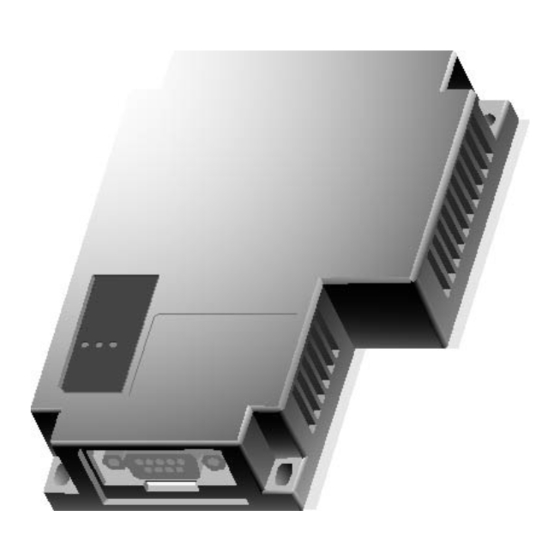
Page 14: Part Name
Chapter 2 Product Specification 2.3 Part Name Each part of Profibus-DP Module has the following name: A A A A Hole for module fixation Sector B B B B LED Sector Category Name Normal Abnormal Description PWR LED Module’s power status When it is in Data Exchange Mode, It turns ON RUN LED - Master parameter error... -
Page 15: Communication Cable Specification
Chapter 2 Product Specification 2.4 Communication Cable Specification Cables that comply with Profibus standard for Profibus-DP shall be used and the Company recommends using the cable with the following specification: 2.4.1 Profibus-DP Cable Specification 1) Cable Specification Category Specification Belden Network Cable Type: Network Components Cable Protocol: FMS-DP... - Page 16 Chapter 2 Product Specification 2) Connector’s structure and connector wire method (1) Input wire: green line is connected to A1, red line is connected to B1. (2) Output wire: green line is connected to A2, red line is connected to B2 (3) Shield is connected to connector’s clamp.
-
Page 17: Chapter 3 Installation And Trial Run
Chapter 3 Installation and Trial Run Chapter 3 Installation and Trial Run 3.1 Installation Environment (This section is as described in 10.1.1. Installation Environment of “XGT Panel User Manual.) This machine has high reliability regardless environment. But for reliability and stability, be careful the followings (1) Environment condition (a) Install at the panel which can protect this machine from water and dust. -
Page 18: Cautionary Notes
Chapter 3 Installation and Trial Run 3.2 Cautionary Notes (This section is as described in 10.1.2 Cautionary Notes of “XGT Panel User Manual”.) It describes the notice from opening to installation. • Do not drop or cause heavy impact. • Do not disassemble voluntarily. When doing this, we are not responsible for the product. •... -
Page 19: Setting Sequence
Chapter 3 Installation and Trial Run 3.3 Setting Sequence This section describes the sequence from setting the product to driving. Install and set parameters to run the system in the following sequence: Start Check functions and standard Power off HMI and mount the module to AUX slot of HMI. -
Page 20: Parameter Setting In Xp-Builder
Chapter 3 Installation and Trial Run 3.4 Parameter Setting in XP-Builder The following parameters can be set up in XP-Builder: Item Range and Content Remark Address 0 ~ 125 10 types Input Size 1 Word ~ 112 Words 10 types Output Size 1 Word ~ 112 Words 3.5 Connection of Product... -
Page 21: Trial Run
Chapter 3 Installation and Trial Run 3.6 Trial Run 3.6.1 Caution in Configuring the System 1) Use the communication cable that has specified dimensions. Using any other cable other than specified ones may cause some serious communication error. 2) Before installing the communication cable, check if the cable is disconnected or has a short circuit. 3) Fasten the communication cable connector to securely fix the cable. -
Page 22: Chapter 4 System Configuration
I/F module I/F module [Figure 4.1.1] Connection between One Master and N XPs 4.1.2 System that consists of One Master, Several XPs and other various Slaves LSIS or other company master Other company device Remote I/O XP Profibus-DP XP Profibus-DP... -
Page 23: Chapter 5 Profibus-Dp Communication
Chapter 5 Profibus-DP Communication Chapter 5 Profibus-DP Communication 5.1 Introduction Profibus-DP Communication between Profibus Master and HMI is a data transmission service that allows the user to send/receive data by setting communication parameters and to easily exchange data by setting parameters related to address and sending/receiving data size with XP-Builder. -
Page 24: Sending/Receiving Processing Of Profibus-Dp Communication
Chapter 5 Profibus-DP Communication 5.2 Sending/Receiving Processing of Profibus-DP Communication This section describes how to use Profibus-DP communication through a setting example to send/receive data between the master station and Profibus-DP I/F module (XGT Panel) of “1” Station’s. Setting is carried out as following: (a) The master station receives 32 words from the sending area (e.g. -
Page 25: Sequence To Operate Profibus-Dp Communication
Chapter 5 Profibus-DP Communication 5.3 Sequence to Operate Profibus-DP Communication Select “XGT Panel Setting XP-Builder’s “Project Property” -> “XGT Panel Setting” Window “XGT Panel Setting Window” Profibus-DP Setting Select “Maker” and “Product” as Profibus Maker, Product Setting Profibus-DP Detailed Setting1 Select one among address 0 through 125 Address Setting Profibus-DP Detailed Setting2... -
Page 26: Profibus-Dp Communication Setting
Chapter 5 Profibus-DP Communication 5.4 Profibus-DP Communication Setting For high-speed link parameters, select high-speed link parameters from XG-PD’s high-speed link screen and set relevant items, which have the following functions, as following setting sequences. 5.4.1 Setting Profibus-DP on XP-Builder (1) Executing XP-Builder If the first XP-Builder is executed and “Project Property”... - Page 27 Chapter 5 Profibus-DP Communication (2) Selecting Profibus-DP After clicking “XGT Panel Setting” from the top tab of the screen above, select “Profibus International” from Item “Maker”. Then, select “Profibus DP Slave” from Item “Product”. 5 - 5...
- Page 28 Chapter 5 Profibus-DP Communication (3) Profibus-DP Detailed Setting If “Detail Setting” is clicked from Item “Protocol” on the same screen, “Aux Card Setting” window will appear and at this time, set “address”, “ Input Size” and “Output Size” (Input/Out Size is designed to be selected among 10 types). [Figure] Profibus-DP Detailed Setting Window (4) Download After returning to the main screen of the first project by pressing ‘Confirm’...
- Page 29 Chapter 5 Profibus-DP Communication If the Download screen below appears, set connections appropriately and execute “Download”. [Figure] Download Window (5) Example of Configuration Setting on the Master The master’s configuration is set with the configuration tools provided by the master manufacturer. At this time, carefully configure in the same way as in XP-Builder to get normal communication.
-
Page 30: Chapter 6 Setting Example
Chapter 6 Setting Example Chapter 6 Setting Example 6.1 Profibus-DP Communication 6.1.1 Example System This chapter describes on how to set Profibus-DP when the user wants to communicate on the following system as seen in [Figure 6.1.1] in the way as specified in [Table 6.1.1]: XP (station 1) Master (station 0) [Figure 6.1.1] System Configuration... -
Page 31: Setting Slave (Xp) Parameter
Chapter 6 Setting Example 6.1.2 Setting Slave (XP) Parameter 1) Set “Profibus-DP ” on “Project Property”-> “XGT Panel Setting”. Click 2) Click on detailed settings on the same screen to set address and Input/Output size as specified in [Table 7.1.1]. At this time, Input/Output’s starting address is set in PI000/ PQ000 automatically. -
Page 32: Setting Master Configuration (In Case Of Sycon)
Chapter 6 Setting Example 6.1.3 Setting Master Configuration (In case of Sycon) Master Configuration for relevant slave(XP) is set with the configuration tool provided by the master manufacturer. At this time, an example is presented to show how to configure by using Sycon (Refer to other manuals for information on other configuration tools). - Page 33 Chapter 6 Setting Example 2) If the user clicks a slave, the configuration setting window will appear. - Click one from Available Slaves list to select. - At this time, the important thing is that only one Input Module and one Output Module shall be selected for configuration and also make sure to start setting one Input Module first.
-
Page 34: Xp-Builder Device Settings
Chapter 6 Setting Example 6.2 XP-Builder Device Settings 6.2.1 Editing Object To connect Profibus-DP Communication data to the relevant object when editing XP screen, 1) Click on the relevant object to open the object window. 2) Click on Device to specify “Profibus-DP Slave”, 3) Specify Data Location from Item “Device Select”. - Page 35 Chapter 6 Setting Example 6 - 6...
-
Page 36: Chapter 7 Diagnosis Function
Chapter 7 Diagnosis Function Chapter 7 Diagnosis Function This chapter describes how to check the status of the system, module and network. It is possible to check the system configuration and Profibus-DP Slave option module’s status through the procedure below. 7.1 Diagnosis Information 7.1.1 Profibus-DP Diagnosis Information Area XP Profibus-DP I/F Module provides information on the current status of Profibus-DP I/F Module and diagnosis information via... -
Page 37: Led Information
Chapter 7 Diagnosis Function 7.1.2 LED Information Since LED status is related to diagnosis information area as following, it is possible to check the system status with LED status at a glance and for further information, it is helpful to monitor DG Register and verify its status. DG001 DG002 Run LED... -
Page 38: Troubleshooting
Chapter 7 Diagnosis Function 7.2 Troubleshooting Abnormal communication Set “Maker”, “Product” as Profibus on the “XGT Panel Do you set communication setting window” option properly? Does communication cable is Connect communication cable and fasten the connected properly? connector properly XP Power Off Does Profibus-DP option Check whether connector pin for AUX module is module is installed at the body... - Page 39 Chapter 7 Diagnosis Function Is “ERR” LED on? Take measures on the corresponding error such as re- configuration, referring to the Is the configuration of the diagnostic information such as master normal? DG000, 001 Is the data exchange normal? Contact A/S center and request repair and substitute Is “ERR”...
-
Page 40: Appendix
4) SyCon Application program of Profibus Network Configuration Tool used to specify the configuration though SyCon and download the information onto the applicable module if LSIS master module (XGL-PMEA) is applied. 5) PROFICON Application program of Profibus Network Configuration Tool used to specify the configuration though PROFICON and download the information onto the applicable module if LSIS master module (XGL-PMEC) is applied. -
Page 41: Dimension
Appendix A.2 Dimension unit: mm A - 2... - Page 42 Warranty and Environmental Policy Warranty 1. Warranty Period The product you purchased will be guaranteed for 18 months from the date of manufacturing. 2. Scope of Warranty Any trouble or defect occurring for the above-mentioned period will be partially replaced or repaired. However, please note the following cases will be excluded from the scope of warranty.
- Page 43 LS values every single customers. Quality and service come first at LSIS. Always at your service, standing for our customers. http://eng.lsis.biz 10310001210 ■ HEAD OFFICE ■ LS Industrial Systems Chengdu Office _ Chengdu, China LS Tower, 127, LS-ro, Dongan-gu, Anyang-si, Gyeonggi-do, 431-848, Korea, Address : 12FL.
Need help?
Do you have a question about the XGT Panel Series and is the answer not in the manual?
Questions and answers