LSIS XGT Series User Manual
Programmable logic controller, cnet i/f module
Hide thumbs
Also See for XGT Series:
- User manual (909 pages) ,
- Manual (48 pages) ,
- User manual (278 pages)

Related Manuals for LSIS XGT Series


Summary of Contents for LSIS XGT Series
- Page 1 Programmable Logic Controller Cnet I/F Module XGT Series User’s Manual XGL-C22A XGL-C22B XGL-CH2A XGL-CH2B XGL-C42A XGL-C42B...
- Page 2 Safety Instructions Before using the product … For your safety and effective operation, please read the safety instructions thoroughly before using the product. Safety Instructions should always be observed in order to prevent accident ► or risk with the safe and proper use the product. Instructions are divided into “Warning”...
- Page 3 Safety Instructions Safety Instructions for design process Warning Please install a protection circuit on the exterior of PLC so that the whole system may operate safely regardless of failures from external power or PLC. Any abnormal output or operation from PLC may cause serious problems to safety in whole system.
- Page 4 Safety Instructions Safety Instructions for design process Caution I/O signal or communication line shall be wired at least 100mm away from a high-voltage cable or power line. Fail to follow this instruction may cause malfunctions from noise Safety Instructions on installation process Caution Use PLC only in the environment specified in PLC manual or...
- Page 5 Safety Instructions Safety Instructions for wiring process Warning Prior to wiring works, make sure that every power is turned off. If not, electric shock or damage on the product may be caused. After wiring process is done, make sure that terminal covers are ...
- Page 6 Safety Instructions Safety Instructions for test-operation and maintenance Warning Don’t touch the terminal when powered. Electric shock or abnormal operation may occur. Prior to cleaning or tightening the terminal screws, let all the external power off including PLC power. If not, electric shock or abnormal operation may occur.
- Page 7 Revision History Revision History Version Data Remark Page V 1.0 2005.03 First Edition V1.1 2005.05 Add function description V1.2 2005.09 Change available CPU device address V2.0 2007.01 Change XG-PD description 1. Adding contents (1) Production Configuration (2) Software to use the product 1-4 ~ 1-5 (3) Operation Sequence (4) I/O assignment and Device Information...
- Page 8 Revision History Version Data Remark Page (27) User interface using Visual Basic A-18 ~ A-29 (28) Dimension A-30 (29) Index A-31 ~ A-32 2. Fixing the contents (1) Introduction (2) Characteristics (3) Performance Specifications (4) Designation of Parts (5) Cable Specifications (6) Terminal Resistance (7) Channel Operation during Normal Run (8) Method of Serial Interface...
- Page 9 3. Add appearance drawing of XGL-Cx2B Appendix 4. Add repeater mode 2019.06 1. Edit phrase Entire V3.1 ※ The number of User’s manual is indicated right part of the back cover. Copyright ⓒ 2005 LSIS Co., Ltd All Rights Reserved.
- Page 10 User’s Manual. The User’s Manual describes the product. If necessary, you may refer to the following description and order accordingly. In addition, you may connect our website (http://www.lsis.com/) and download the information as a PDF file. Relevant User’s Manuals...
- Page 11 Contents ◎ Contents ◎ Chapter 1 Overview 1.1 Introduction--------------------------------------------------------------------------------------------------------------------------------------- 1-1 1.2 Characteristics----------------------------------------------------------------------------------------------------------------------------------- 1-2 1.3 Product Configuration------------------------------------------------------------------------------------------------------------------------- 1-3 1.3.1 Type name indication-------------------------------------------------------------------------------------------------------------- 1-3 1.3.2 The max. number of module by CPU---------------------------------------------------------------------------------------- 1-3 1.4 Software to use the product----------------------------------------------------------------------------------------------------------------- 1-4 1.4.1 Software check point-------------------------------------------------------------------------------------------------------------- 1-4 1.4.2 XG5000 ------------------------------------------------------------------------------------------------------------------------------- 1-4 1.4.3 Check version----------------------------------------------------------------------------------------------------------------------- 1-5 Chapter 2 Product Specifications...
- Page 12 Contents Chapter 5 System Configuration 5.1 Available System Configurations --------------------------------------------------------------------------------------------------------- 5-1 5.1.1 1:1 connection (no modem) to PC (HMI) -------------------------------------------------------------------------------------- 5-1 5.1.2 1:1 dedicated line modem connection to PC (HMI) ------------------------------------------------------------------------ 5-1 5.1.3 Modem connection to PC & Communication between Cnet I/F modules-------------------------------------------- 5-2 5.1.4 Dedicated communication with PC (HMI) &...
- Page 13 Contents Chapter 7 XGT Dedicated Communication 7.1 Summary of Protocol ------------------------------------------------------------------------------------------------------------------------- 7-1 7.1.1 Summary ------------------------------------------------------------------------------------------------------------------------------- 7-1 7.2 Frame Structure -------------------------------------------------------------------------------------------------------------------------------- 7-2 7.2.1 Frame structure ----------------------------------------------------------------------------------------------------------------------- 7-2 7.2.2 Instruction list --------------------------------------------------------------------------------------------------------------------------- 7-4 7.2.3 Writing the single direct variable (W(w)SS)------------------------------------------------------------------------------------ 7-6 7.2.4 Reading single direct variable (R(r)SS) ---------------------------------------------------------------------------------------- 7-8 7.2.5 Writing the direct variable continuously (W(w)SB)------------------------------------------------------------------------- 7-11 7.2.6 Reading direct variable continuously (R(r)SB) ----------------------------------------------------------------------------- 7-13 7.2.7 Registration and execution of monitor variable ---------------------------------------------------------------------------- 7-15...
- Page 14 Contents Chapter 9 Modbus Communication 9.1 General ------------------------------------------------------------------------------------------------------------------------------------------- 9-1 9.1.1 Procedure of Modbus communication ---------------------------------------------------------------------------------------- 9-1 9.2 Modbus Protocol ------------------------------------------------------------------------------------------------------------------------------- 9-1 9.2.1 Kind of Modbus protocol ------------------------------------------------------------------------------------------------------------ 9-1 9.2.2 Structure of Modbus protocol ------------------------------------------------------------------------------------------------------ 9-2 9.3 Frame Structure -------------------------------------------------------------------------------------------------------------------------------- 9-3 9.3.1 Frane structure in the ASCII mode --------------------------------------------------------------------------------------------- 9-3 9.3.2 Frame structure in the RTU mode ---------------------------------------------------------------------------------------------- 9-3 9.3.3 Data and expression of address ------------------------------------------------------------------------------------------------ 9-4...
- Page 15 Contents Chapter 11 Program Examples 11.1 Setting of Cnet I/F module in the XG5000 ---------------------------------------------------------------------------------------- 11-1 11.1.1 In case of acting as server -------------------------------------------------------------------------------------------------- 11-2 11.1.2 In case of acting as P2P service (client) -------------------------------------------------------------------------------- 11-4 11.2 XGT Communication -------------------------------------------------------------------------------------------------------------------- 11-7 11.2.1 Settings of XGT server ------------------------------------------------------------------------------------------------------- 11-8 11.2.2 Settings when acting as XGT client ------------------------------------------------------------------------------------- 11-10 11.2.3 Checking the operation ---------------------------------------------------------------------------------------------------- 11-14...
- Page 16 Chapter 1 Overview Chapter 1 Overview 1.1 Overview This user's manual provides a description of contents related to the interface module Computer Link (Cnet I/F module) used in the XGK/I/R PLC system. You can connect to other companypanyct to other companyse computer, exchange data or control the PLC remotely by using the Cnet I/F module.
- Page 17 (12) Remote connection while the XGT Cnet I/F modules are communicating with each other is Note 1) available. (13) The client mode (LS bus) for dedicated communication with the LSIS Co.,Ltd.'s inverter is Note 2) provided. (14) The smart server recognizes protocol (LSIS Co.,Ltd.'s dedicated communication protocol, modbus Note 2) RTU/ ASCII) automatically and operates.
- Page 18 Chapter 1 Overview Notes Note 1) The remote connection between the Cnet I/F modules can be used only when the OS version of the Cnet I/F module is V2.5 or higher. Matters related to remote connection are as follows. (1) This function is supported only when the RS-232C or RS-422 communication methods are used.
- Page 19 Chapter 1 Overview 1.3 Product configuration 1.3.1 Type of product The type of Cnet I/F module is as follows. Model name Specifications Note XGL-C22A/C22B RS-232C, two ports XGL-CH2A/CH2B RS-232C one port, RS-422 one port Twist pair shield cable XGL-C42A/C42B RS-422, two ports 1.3.2 Number of units that can be installed for each CPU Up to 24 Cnet I/F modules can be installed regardless of the default base and the extension base.
- Page 20 Check the following items for correct use of the product. 1.4.1 Prior preparation (1) Download the XG5000 from the LSIS Co., Ltd.'s homepage. Website address: http://www.lsis.co.kr/ (2) Prepare the cable necessary for connecting the XG5000 and the CPU module. The model name of the cable is as follows.
- Page 21 Chapter 1 Overview 1.4.3 Checking the product version Be sure to check the version of the relevant product before using the Cnet I/F module. (1) Method to check the version using XG5000 This is the method to connect to the CPU module and read the product information of the Cnet I/F module.
- Page 22 Chapter 2 Product specifications Chapter 2 Product specifications 2.1 General specifications The general specifications of the XGT series are as follows. Relevant Item Specifications specifications Ambient 0℃∼+55℃ temperature Storage -25℃∼+70℃ temperature 5∼95%RH, Non-condensing Ambient humidity 5∼95%RH, Non-condensing Storage humidity In case of occasional vibration...
- Page 23 Asynchronous type BYTE SUM, WORD SUM, BYTE XOR, DLE AB, DLE SIEMENS, Error detection LSIS CRC, CRC 16, BYTE SUM 2’S COMP, BYTE SUM 1’S COMP 7BIT SUM, 7BIT XOR, CRC 16 IBM, CRC 16 CCITT Possible to select among 300/600/1,200/1,800/2,400/3,600/4,800/7,200/9,600...
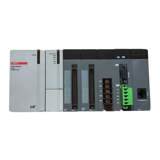
- Page 24 Chapter 2 Product specifications 2.3 Name and usage of each part (1) Front view of the product [A type Cnet I/F module] [B type Cnet I/F module] (2) Name and usage of each part Name Usage ① Indicator LED Refer to Paragraph (3) below. RS-232C or RS-422/485 connector for serial communication with the ②...
- Page 25 The following table shows the cable specifications recommended by LSIS Co., Ltd. In case of using any other cables, be sure to apply a cable that meets the characteristics shown in the following table.
- Page 26 Chapter 2 Product specifications 2.5 Terminating resistance When the RS-422 or RS-485 channel of the A type Cnet I/F module (XGL-CH2A, C42A) is used, the terminating resistance should be connected to the outside. In case of long-range communication, signal distortion occurs due to the reflected wave of the cable, and the terminating resistance prevents it. In case the cable recommended in Paragraph 2.4 is used, connect the 1/2W, 120Ω...
- Page 27 It operates as the server in the network, and either the XGT server or the modbus server can be selected. (1) XGT server: It supports the LSIS Co.,Ltd.'s dedicated communication protocol and it operates according to the client’s request. (2) Modbus server: It supports the modbus protocol, and the RTU/ASCII type can be selected.
- Page 28 Chapter 3 Performance specifications 3.2 Operation by channel Since each communication port operates independently, it can carry out transmission and reception simultaneously. Therefore, it is possible to set the transmission specifications separately for RS-232C and RS-422 channel and start and stop the operation for each channel. The data flow of each channel is as shown in the figure below.
- Page 29 Chapter 3 Performance specifications 3.3 Additional functions 3.3.1 Repeater mode The repeater mode is the function to transmit data received from each channel to another channel. (1) The repeater mode is only supported in the B type Cnet I/F module (XGL-CH2B, XGL-C42B). (2) The repeater mode does not support auto speed.
- Page 30 Chapter 3 Performance specifications 3.4 Serial connection method 3.4.1 RS-232C connection The RS-232C channel communicates with an external device using the 9-pin connector. The specifications of the RS-232C interface are as follows. Direction of signal (Cnet ↔ external Pin No. Signal name Content device) Notifies to Cnet that the external device has detected...
- Page 31 Chapter 3 Performance specifications (2) How to connect the RS-232C connector if the null modem mode is used If the null modem mode is used, connect in three lines as follows (no handshake). Computer/commun Cnet (9-pin) ication device Pin No. and direction of signal Signal Pin No.
- Page 32 Chapter 3 Performance specifications 3.4.2 RS-422/485 connection The RS-422 channel communicates with an external device using the 5-pin connector for the A type module and the 6-pin connector for the B type module. The specifications of the RS-422 interface are as follows. Direction of signal Pin No.
- Page 33 Chapter 4 Installation and trial operation Chapter 4 Installation and trial operation 4.1 Installation environment High quality level of the Cnet I/F module has been secured in order for it to be used in various environments. However, the following contents should be observed in order to guarantee the reliability and stability of this product.
- Page 34 Chapter 4 Installation and trial operation 4.2 Caution in handling A description of matters requiring caution when handling the product is provided. (1) Do not drop or impact the product. (2) Do not open the product case or disassemble the product arbitrarily. (3) When wiring, make sure that wiring waste does not enter the product.
- Page 35 Chapter 4 Installation and trial operation 4.3 Product operation method A description of contents to be executed for operating the product is provided. Operate and set the product according to the following procedure to ensure correct product operation. Start Check the function and specifications you wish to apply.
- Page 36 Chapter 4 Installation and trial operation 4.4 Contents of parameters for each communication mode Parameters that should be set in XG5000 according to the communication mode are as follows. 4.4.1 Default setting parameters Setting availability Setting range and Parameter Setting item Note menu contents...
- Page 37 Chapter 4 Installation and trial operation Notes Note 1) Response waiting time: It means the time to receive the response frame after transmitting a frame. (1) It can be set when P2P is set for the operation mode. (2) Response waiting time = Basic response waiting time + (response waiting time setting value x 100ms) + Inter- character waiting time (3) Basic response waiting time for each communication speed...
- Page 38 Chapter 4 Installation and trial operation 4.4.2 P2P setting parameter Setting availability (client) User Inverter Setting range frame Parameter Sub menu Setting item Modbus Modbus Dedicated and contents definition ASCII communic communicati ation Commun Base Possible Possible Possible Possible Possible ication module Slot...
- Page 39 Chapter 4 Installation and trial operation Notes Note 1) In the case of user-defined frame communication, the starting condition can be selected only when the P2P function is SEND. Note 2) The number of variables and the data size can be set only when the method is continuous in the XGT/modbus ASCII/modbus RTU client.
- Page 40 Chapter 4 Installation and trial operation 4.5 I/O assignment and device information 4.5.1 I/O assignment (1) When the XGK CPU is used (a) Basic system configuration method The default base and the extension base are connected using a cable, and the characteristics of the configured basic system are as follows.
- Page 41 Chapter 4 Installation and trial operation (2) When XGI CPU is used (a) Basic system configuration method XGI-CPUU / CPUH / CPUU/D Classification XGI-CPUS XGI-CPUE / CPUUN Maximum number 7 stages 3 stages 1 stage of extension stages Maximum number of I/O modules to 96 modules 48 modules...
- Page 42 Chapter 4 Installation and trial operation (3) When XGR CPU is used (a) Basic system configuration method Classification Description Configuration of Install two basic bases in the same configuration in duplicate. basic base Maximum extension Up to 31 extension bases can be installed. base Maximum number of I/O...
- Page 43 Chapter 4 Installation and trial operation 4.5.2 Device information (1) Basic setting Statio Respons Inter- Communi Communi Data Stop Parity Modem Modem Delay character cation cation type initialization addre Waiting time waiting type speed time time Null modem Disable (space) 0~31 0~50 0~255...
- Page 44 Chapter 4 Installation and trial operation (3) P2P channel setting Port of Client/ IP address of Channel Operation mode P2P driver TCP/UDP destination server destination station station XGT server XGT client User frame definition LS bus client (B type Cnet I/F Use P2P module) Modbus ASCII client...
- Page 45 Chapter 4 Installation and trial operation (5) User frame definition setting Group Frame Segment Note Up to 10 bytes Numerical constant 12345678901234567890 HEAD 1234567890 String constant (3132..30 is registered internally.) Up to 10 bytes Numerical constant 12345678901234567890 TAIL 1234567890 Transmission String constant (3132..30 is registered internally.) Up to 10 bytes...
- Page 46 Chapter 4 Installation and trial operation 4.5.3 Available device areas for each CPU type Area Range Size (word) Note Type P0~P2047 2,048 Possible to read, write and monitor M0~M2047 2,048 Possible to read, write and monitor K0~K2047 2,048 Possible to read, write and monitor Possible to read and monitor (write: possible F0~F2047 2,048...
- Page 47 Chapter 5 System configuration Chapter 5 System configuration Up to 24 Cnet I/F modules including the default base and the extension base can be installed regardless of the CPU module. Among these modules, up to 8 modules can be used for the P2P service, and all 24 modules can be used in the server mode.
- Page 48 Chapter 5 System configuration 5.1.2 Configuration case 2 (1) This system connects the PC (HMI) and the PLC in one to one through the dedicated line modem. (2) The PC (HMI) operates as the client station and the Cnet I/F module operates as the server station that responds to the request of the PC (HMI).
- Page 49 Chapter 5 System configuration 5.1.3 Configuration case 3 (1) This system connects the PC(HMI) and the PLC through the modem and PLCs communicate to each other through the Cnet I/F module. (2) PC and Cnet #1 station are connected using the modem through the RS-232C channel. (3) Cnet #1 station ~ N station carry out the communication between Cnet I/F modules through the RS- 422 channel.
- Page 50 Chapter 5 System configuration 5.1.4 Configuration case 4 (1) HMI(PC) and PLC carry out the null-modem communication using the RS-232C channel and PLC is the system that connects Smart I/O through the RS-422 channel. (2) HMI(PC) operates as the client station and the Cnet I/F module operates as the server station. At this time, the module is set as RS-232C XGT server.
- Page 51 Chapter 5 System configuration 5.1.5 Configuration case 5 (1) This is the system that communicates using the wireless modem in an application field where an object which carries out a rectilinear motion is handled. (2) HMI and PLC can carry out the dedicated mode communication or P2P communication. (3) Cnet I/F module can carry out RS-232C/RS-422 communication with the optical modem.
- Page 52 Chapter 5 System configuration 5.1.6 Configuration case 6 (1) This is the system that communicates using the wireless modem in an application field where a rotating object is handled. (2) Wireless modem and PLC carry out the RS-232C communication. (3) Cnet I/F modules carry out the dedicated server/client communication. (4) The RS-232C channel of the Cnet I/F module uses the dedicated modem mode.
- Page 53 Chapter 5 System configuration 5.1.7 Configuration case 7 (1) This is the TM/TC communication system that carries out long distance communication with the client PLC remotely using the dedicated line modem. (2) The RS-232C channel is set for the dedicated line modem mode and dedicated modem communication is carried out.
- Page 54 Chapter 5 System configuration 5.2 System configuration that cannot be applied 5.2.1 Dial-up modem communication between Cnet I/F modules (conditional) (1) The Cnet I/F module has the function to answer the phone but it does not have the dialing function. (2) Therefore, the Cnet I/F modules cannot communicate with each other using the dial-up modem.
- Page 55 Chapter 5 System configuration 5.2.2 XG5000 connection using the RS-422 channel of the Cnet I/F module (1) The XG5000 service of the Cnet I/F module is supported only for the RS-232C channel. Therefore, XG5000 cannot be connected using the RS-422 channel. (2) The remote connection of the XG5000 has no function to set the station address of the Cnet.
- Page 56 Chapter 6 Communication parameters Chapter 6 Communication parameters 6.1 Overview The communication parameters can be classified into the default setting parameters and the P2P setting parameter. 6.1.1 Default setting parameters This is the part where the media information, H/W information and basic protocol information of the Cnet I/F module are set.
- Page 57 Chapter 6 Communication parameters (1) P2P service (a) This service makes the Cnet I/F module operate as the client in the network. (b) If a prescribed event occurs, it is possible to read or write the memory of the opposing station (It can operate as the XGT client and the modbus client.).
- Page 58 Chapter 6 Communication parameters 6.1.2 P2P setting parameter This is the part for setting the communication frame. Paramet Setting range and Sub menu Setting item Content contents Communic Base 0~7(0~31:XGR) ation Set the module installation position Module Slot 0~11 setting User frame definition XGT client Modbus ASCII...
- Page 59 Chapter 6 Communication parameters 6.1.3 Transmission specifications In order to use the Cnet I/F module correctly, the various specifications including the communication speed and data format on the [Basic setting] item of the registered Cnet I/F module should be set. Basic setting value is saved to the CPU module of the PLC, and this value is maintained continuously even if the power is turned off;...
- Page 60 Chapter 6 Communication parameters 6.2 Module registration method In order to use the Cnet I/F module, the communication parameter should be set using XG5000, and the system setting can be carried out only when the relevant module is registered to the XG5000.
- Page 61 Chapter 6 Communication parameters 6.2.2 Registering in online status The method to set the module and communication parameter while connected to the PLC is as follows. (1) As explained in 6.2.1, click [New project] and specify the project name, file location and CPU type. (2) If the connection to the PLC is not made properly, check the connection status and select [Online]→[Connection setting] or click the icon ( ) and select the connection method.
- Page 62 Chapter 6 Communication parameters (3) When the connection is made normally, select [Online]→[Diagnosis]→[I/O information] while the CPU module is in stop mode. (4) Click the [I/O synchronization] button. (5) Check the contents shown in the Message window, and if there is no problem click [Yes].
- Page 63 Chapter 6 Communication parameters 6.2.3 Reading the parameter value saved on PLC The method to read the basic setting value of communication module and P2P setting value saved on PLC is as follows. (1) Select [Project] → [Open from PLC]. (2) Set [Connection method] and [Connection step] and click [Connect] or [OK].
- Page 64 Chapter 6 Communication parameters 6.3 Transmission specifications setting method In order to operate the Cnet I/F module properly, the communication parameter should be set according to the applied specifications. It can be explained as follows by considering XGL- CH2A(RS232 1port, RS422 1port) installed on No. 0 base and No. 0 slot 0 as an example. (1) Channel setting (a) Channel 1: RS-232C, 9,600 bps, 8/1/None, null modem, XGT server, station 1 (b) Channel 2: RS-422, 38,400 bps, 8/1/Odd, null modem, use P2P, station 2...
- Page 65 Chapter 6 Communication parameters (3) Write parameter 1) Select [Online]→[Write] or click the icon ( 2) Put a check mark on the module whose basic setting is completed () and click the [OK] button. (b) Check operation 1) Select [Online]→[Communication module setting]→[System diagnosis] or click icon ( 2) Click a communication module you wish to diagnose from the [System diagnosis] window and click the right mouse button.
- Page 66 Chapter 6 Communication parameters 6.4 Parameter setting method for each service 6.4.1 Dedicated service The dedicated service is the built-in function of Cnet I/F module to read or write PLC information or data using PC or an external device without a separate program in PLC. When this function is used, the Cnet I/F module operates as the server, and when PC or an external device requests for read/write memory, it responds.
- Page 67 Chapter 6 Communication parameters The modbus commands and the maximum number of response data supported by the modbus RTU/ASCII driver are as shown in the following table. The opposing client device is used within the range shown in this table. For example, Read bit can be requested for up to 2000 bits, and Write bit can be requested for up to 1968 bits (When the modbus RTU is used).
- Page 68 Chapter 6 Communication parameters 6.4.2 P2P service The P2P service is the function to operate the Cnet I/F module as the client. In GLOFA series and MASTER-K series, the parameters were set using the command block, but in XGT series, the parameters can be set simply from the [P2P parameter setting] window. The P2P commands that can be used in the Cnet I/F module are four commands including Read, Write, Send and Receive.
- Page 69 Chapter 6 Communication parameters (1) P2P parameter configuration In order to use the P2P service, each parameter should be set in the P2P parameter window. As shown in the figure below, the P2P parameter consists of three pieces of information. (a) P2P channel 1) Define a communication protocol for carrying out the P2P service.
- Page 70 Chapter 6 Communication parameters (2) P2P channel setting The Cnet I/F module provides two communication channels that operate independently, and the driver type for carrying out the P2P service can be defined for each channel. However, in order for the P2P channel to operate as the client, ‘Use P2P should be selected for the operation mode in the [Basic setting] window.
- Page 71 Chapter 6 Communication parameters (3) P2P block setting When the P2P block of the relevant parameter is selected in the [P2P parameter setting] window, the [P2P block setting] window will be displayed. The block setting window for all protocols is as shown in the figure below, and a different area which is enabled according to the protocol selected from P2P channel is displayed.
- Page 72 Chapter 6 Communication parameters 6.5 Starting operation The operation mode of the Cnet I/F module can be divided into the P2P service and the server function. The method to use each mode is as follows. 6.5.1 In case of operating as the server (1) Connection setting (a) Select [Online]→[Connection setting] or click the icon ( (b) Set the connection option that fits the user environment and click [Connect].
- Page 73 Chapter 6 Communication parameters (4) Selecting the operation mode (a) Select the operation mode of the service you wish to use. (b) The Cnet I/F module supports the XGT server, modbus ASCII server and modbus RTU server. (5) Write parameter (a) Select [Online]→[Write] or click the icon ( (b) Put a check mark on the module whose default setting is completed () and click [OK].
- Page 74 Chapter 6 Communication parameters (6) Check operation (a) Select [Online]→[Communication module setting]→[System diagnosis] or click the icon ( (b) Click a communication module whose status you wish to diagnose and click the right mouse button. (c) When the following screen is displayed, click [Frame monitor] or [Status by service] and check the operation status.
- Page 75 Chapter 6 Communication parameters 6.5.2 In case of operating as the P2P service (client) (1) Basic setting (a) The contents in Paragraph 6.6.1 and (1)~(3) are the same. * Set 7 for the data bit in case of operating as the modbus ASCII client. (b) Select ‘Use P2P’...
- Page 76 Chapter 6 Communication parameters (3) P2P block setting (a) A different P2P block setting value is enabled according to the type of client selected from the channel setting. (b) Write the content of the enabled cell according to the protocol type. * The user frame definition can be used only when the frame is written in the user frame definition.
- Page 77 Chapter 6 Communication parameters 1) Link enable through a flag The following is the method to enable the link using a flag. In order to use this function, the software version of XG5000 and CPU module should satisfy the following condition. Item name Version XG5000...
- Page 78 Chapter 6 Communication parameters Flag Data type Device Content speed link NO. 12 Request enable/disable for high speed _HS1_REQ F10300 link No. 1 Request enable/disable for high speed _HS2_REQ F10301 link No. 2 Request enable/disable for high speed _HS3_REQ F10302 link No.
- Page 79 Chapter 6 Communication parameters Flag Data type Device Content _P2P2_REQ F10321 Request enable/disable for P2P No. 2 _P2P3_REQ F10322 Request enable/disable for P2P No. 3 _P2P4_REQ F10323 Request enable/disable for P2P No. 4 _P2P5_REQ F10324 Request enable/disable for P2P No. 5 _P2P6_REQ F10325 Request enable/disable for P2P No.
- Page 80 Chapter 6 Communication parameters (6) Check operation (a) Select [Online]→[Communication module setting]→[System diagnosis] or click the icon ( (b) Click a communication module whose status you wish to diagnose and click the right mouse button. (c) When the following screen is displayed, click [Frame monitor] or [Status by service] and check the operation status.
- Page 81 Chapter 6 Communication parameters 6.6 XG5000 diagnosis function 6.6.1 Type of diagnosis function You can check the system and network status using the diagnosis function of the XG5000. Main items that can be diagnosed are as follows. CPU status ...
- Page 82 Chapter 6 Communication parameters 6.6.2 Checking the CPU status (1) CPU module information (a) Select [Online]→[Communication module setting]→[System diagnosis] or click icon ( (b) Click CPU module and click the right mouse button. (c) When you click [CPU module information], the screen where you can check the status of CPU module will be displayed as follows.
- Page 83 Chapter 6 Communication parameters 6.6.3 Communication module information (1) Communication module information (a) Select [Online]→[Communication module setting]→[System diagnosis] or click icon ( (b) Click Cnet I/F module and click the right mouse button. (c) When you click [Communication module information], the screen where you can check the status of communication module will be displayed as follows.
- Page 84 Chapter 6 Communication parameters 6.6.4 Frame monitor The user can check whether a frame transmitted or received through Cnet I/F module is normal or not by using the frame monitor of XG5000. (1) Frame monitor (a) Select [Online]→[Communication module setting]→[System diagnosis] or click icon ( (b) Click Cnet I/F module and click the right mouse button.
- Page 85 Chapter 6 Communication parameters 6.6.5 Loop-back test (1) Prior preparation (a) Be sure to set the server operation mode for the relevant module. (b) Disable the P2P link enable of the relevant module (uncheck). (c) Wire according to each communication port as shown in the figure below. 1) RS-232C communication: Connect No.
- Page 86 Chapter 6 Communication parameters 6.6.6 Status by service (1) Dedicated service (a) Select [Online]→[Communication module setting]→[System diagnosis] or click icon ( (b) Click Cnet I/F module and click the right mouse button. (c) Click [Status by service], and when the following screen is displayed, select [Dedicated service]. (d) Click [Read continuously] and check the status of each service.
- Page 87 Chapter 6 Communication parameters (3) Detailed contents of each service Classification Item Content Base position of the relevant module that uses the Base number dedicated service Basic informatio Slot position of the relevant module that uses the Slot number dedicated service Link type Type of communication module which is being used Dedicated...
- Page 88 Chapter 6 Communication parameters 6.6.7 Media information It is used to determine whether communication is normal or not by providing the media status and service status statistics of the Cnet I/F module. This function is provided by the B type Cnet I/F module.
- Page 89 Chapter 7 XGT communication 7.1 Overview of XGT protocol XGT protocol is the exclusive protocol for Cnet developed by LSIS Co., Ltd. By using this protocol, you can connect to the PLC, read or write data, register a monitor variable and carry out monitoring, and connect to a PLC a long distance away remotely, and read or write in the program.
- Page 90 Chapter 7 XGT communication 7.2 Frame structure 7.2.1 Frame structure The frame of the XGT protocol is classified into the frame where the XGT client requests read/write data and the frame where the XGT server responds to such a request. (1) Command frame sequence When the client transmits a request frame to the server, the server analyzes the received frame.
- Page 91 Chapter 7 XGT communication (3) Characteristics of frame (a) In case of numeric data of all frames, a Hex value is expressed in ASCII code, unless specified otherwise. (b) Items expressed as a Hex value are as follows. 1) Station address 2) Command type in case the command type is a number (indicates the data type) when the main command is R(r) and W(w) 3) Whole items that indicate the size of all data in the structured data area...
- Page 92 Chapter 7 XGT communication 7.2.2 XGT communication commands (1) Type of command The types of commands used in the dedicated communication are as follows. Command Classification Contents of process Main command Command type Item ASCII ASCII Read Read bit and word-type variable r(R) h72(h52) h5353...
- Page 93 Chapter 7 XGT communication (3) Available device area CPU type Area Range Size (word) Note P0~P2047 2,048 Possible to read, write and monitor M0~M2047 2,048 Possible to read, write and monitor K0~K2047 2,048 Possible to read, write and monitor Possible to read and monitor F0~F2047 2,048 (write: possible from 1025 words)
- Page 94 Chapter 7 XGT communication 7.2.3 Write direct variable individually (W(w)SS) This is the function to specify the PLC device memory to be used directly and write according to the memory data type. (1) Example of the XGT client's request frame for write individually Varia Station Comm...
- Page 95 Chapter 7 XGT communication (1) The device data type of each block should be same. (2) If the data type is bit, the data you wish to write will be expressed as hex 1 byte. In other word, h00(3030) should be set if the bit value is 0, and h01(3031) should be set if the bit value is 1.
- Page 96 Chapter 7 XGT communication 7.2.4 Write direct variable individually (R(r)SS) This is the function to specify and read the PLC device according to the data type. 16 independent device memories can be read at a time. (1) Example of XGT client's read individually request frame Comma Variabl ㆍㆍ...
- Page 97 Chapter 7 XGT communication Classification Content ▶ It indicates the number of Hex type byte, and it is converted into ASCII. ▶ This number is determined according to the data type (X,B,W,D,L) included in the name of the direct variable in the format requested by the external communication device.
- Page 98 Chapter 7 XGT communication (4) Example of usage The case of reading M0020 1 word and P0001 1word on station address No. 1 is explained as an example. (At this time, assume that h1234 is in M0020 and h5678 data is in P0001.) (a) XGT client's read individually request frame Statio Comm...
- Page 99 Chapter 7 XGT communication 7.2.5 Write direct variable continuously (W(w)SB) This is the function to write continuously as much data as the specified length, starting from the specified address of the device. (1) Example of XGT client's write continuously request frame Statio Comma Varia...
- Page 100 Chapter 7 XGT communication (4) Example of usage The case of writing 2 bytes hAA15 on D000 of No. 1 station is explained as an example. (a) XGT client’s write continuously request frame Comma Numbe Classificati Head Station Comman Variable Variable Frame r of...
- Page 101 Chapter 7 XGT communication 7.2.6 Read direct variable continuously (R(r)SB) This is the function to read continuously as much data as the specified quantity, starting from the specified address of the PLC device. (1) Example of XGT client's read continuously request frame Station Variabl Classifica...
- Page 102 Chapter 7 XGT communication (4) Example of usage The case of reading 2 words from the M000 address of station address 10 (h0A) is explained as an example. (Assume that the following data is in M000 and M001.) M000 = h1234 M001 = h5678 (a) XGT client’s read continuously request frame Station...
- Page 103 Chapter 7 XGT communication 7.2.7 Registering and executing the monitor variable (1) Registering the monitor variable (X##) Up to 32 monitor variables (from No. 0 to No. 31) can be registered individually in combination with actual read variable command, and when the variables are registered, the registered contents can be executed using the monitor command.
- Page 104 Chapter 7 XGT communication (d) Example of usage The case of registering the monitor of device M0000 in station address No. 1 with device number 01 is explained as an example. 1) XGT client's monitor variable registration frame Registration format Registrat Classificatio Head...
- Page 105 Chapter 7 XGT communication b) If the registered format of the registration number is read direct variable continuously Registrat Fram Classific Station Comman Number Header Data Tail ation address of data number check Frame Y(y) 9183AABB h393138334141424 h3130 h59(79) h3039 h3034 2) In case the NAK responds Classifi...
- Page 106 Chapter 7 XGT communication 7.2.8 Error code When the XGT client transmits the request frame to the server, the server analyzes the received request frame, and if the frame is normal, the server transmits the ACK response frame, and if the frame is abnormal, the server transmits the NAK frame with the error code attached.
- Page 107 Chapter 7 XGT communication 7.3 XGT communication function 7.3.1 Overview The XGT communication operates as either XGT server or P2P service depending on what is set for the operation mode of the Cnet I/F module. XG5000 is set for each mode. (1) XGT server (a) It allows you to read or write PLC information or data from/to PC or peripheral equipment without writing a separate program in PLC.
- Page 108 Chapter 7 XGT communication 7.3.2 Setting parameters in case of using as the XGT server (1) Connection setting (a) Select [Online]→[Connection setting]. (b) Set the connection option that fits the user environment and click [Connect]. (2) Reading I/O information Click [I/O synchronization] from the [Online]→[Diagnosis]→[I/O information] window and read the information on the module currently installed on the base.
- Page 109 Chapter 7 XGT communication (4) Select operation mode Select XGT server. (5) Write parameter (a) Select [Online]→[Write]. (b) Put a check mark on the module whose basic setting is completed from [Basic setting] and click [OK]. (c) Reset the module. (6) Check operation (a) Select [Online]→[Communication module setting]→[System diagnosis].
- Page 110 Chapter 7 XGT communication 7.3.3 Setting parameters in case of using as the XGT client (1) P2P parameter configuration In order to use the P2P service, necessary contents for operation should be set in the P2P parameter window. As shown in the figure below, the P2P parameter consists of three pieces of information.
- Page 111 Chapter 7 XGT communication (a) Operation mode The drivers that can be selected when ‘Use P2P’ is selected for the operation mode are as follows. Driver Usage It is used for transmitting or receiving a desired user defined User frame definition frame.
- Page 112 Chapter 7 XGT communication (3) P2P block setting When the P2P block of the relevant parameter is selected in the [P2P parameter setting] window, the [P2P block setting] window will be displayed. The block setting window for all protocols is as shown in the figure below, and a different area which is enabled according to the protocol selected from P2P channel is displayed.
- Page 113 Chapter 7 XGT communication 3) Basic setting a) Open the [Basic setting] window by double clicking the relevant Cnet I/F module, and set the communication type, communication speed, modem type, data bit, stop bit and station address from the connection setting menu. b) The modem can be initialized only when the modem type is the dial-up modem.
- Page 114 Chapter 7 XGT communication Number Type Block type Content The name of the setting driver changes according to the Channel driver set in the P2P driver. 1.Read: It is used for reading any data from the destination station. function 2.Write: It is used for writing any data on the destination station.
- Page 115 Chapter 7 XGT communication (c) Link enable 1) Select [Online]→[Communication module setting]→[Link enable]. 2) Put a check mark on the P2P block you wish to use and click [Write]. (d) Check operation 1) Select [Online]→[Communication module setting]→[System diagnosis]. 2) Click the relevant module and click the right mouse button. 3) Click [Frame monitor] or [Status by service] and check the operation status.
- Page 116 Chapter 7 XGT communication 7.3.4 Frame monitor When you use the frame monitoring function provided by the XG5000, you can check a frame which is actually exchanged by the client and the server. (1) Check operation (a) Select [Online]→[Communication module setting]→[System diagnosis]. (b) Click the relevant module and click the right mouse button.
- Page 117 Chapter 7 XGT communication 7.3.5 Parameter setting case (1) Setting example in case of using as the XGT client This is an example that data in the P0200 address of the XGT server is read and the frame where 1 word is saved on the M200 address of the self station PLC as the P2P parameter of XG5000 when the M00001 contact point becomes On.
- Page 118 Chapter 7 XGT communication 7.4 Remote connection 7.4.1 Overview If the PLC is remote, you can carry out program download, upload, program debugging and monitoring remotely by using the remote connection function of the Cnet I/F module. You can access PLC wherever it is by using the Cnet I/F module and the XG5000 effectively. The remote connection function can be used in a system where PLCs are connected using the Cnet I/F module and a system where the XG5000 and PLC are connected through the modem.
- Page 119 Chapter 7 XGT communication 7.4.3 Remote 1-stage connection Remote 1-stage connection refer to the connection to PLC2 station in case of a system configured as shown in the figure in Paragraph 7.4.2, and the connection method is as follows. (1) Click Connection setting and select Remote 1-stage for the connection stage. (2) General (a) Timeout time in case communication failed: It indicates the time taken until the timeout process when there is no response from the PLC even though the connection to PLC has been attempted.
- Page 120 Chapter 7 XGT communication (b) Click [Setting] and set the detailed information of the RS-232C and the remote 1-stage. (c) Detail setting of RS-232C 1) Communication port: Indicates the communication port of the computer where XG5000 is installed. 2) Communication speed: 38,400 bps and 115,200 bps are supported for the communication speed. (d) Detail setting of remote 1-stage 1) Network type: Indicates the communication module for remote connection.
- Page 121 Chapter 7 XGT communication 7.4.4 Remote 2-stage connection Remote 2-stage connection refers to the connection to PLC3 station in case of a system configured as shown in the figure in Paragraph 7.4.2, and the connection method is as follows. (1) Click Connection setting and select Remote 2-stage for the connection stage. (2) When you click [Preview], the following screen will be displayed.
- Page 122 Chapter 7 XGT communication (a) Detail setting of remote 1-stage 1) Network type: Indicates the communication module for remote connection. Select XGT Cnet. 2) Local communication module: Select the installation position of the Cnet I/F module operating as local and the channel to be used. 3) Remote 1-stage communication module: Select the station address of the Cnet I/F module that carries out the remote connection.
- Page 123 Chapter 7 XGT communication 7.5 Modem communication 7.5.1 Overview of modem communication The Cnet I/F module has a restriction in the transmission distance according to each communication type (RS-232C: 15m, RS 422/485: A type 500m, B type 1,200m). However, you can control a PLC at great distance by using the modem.
- Page 124 Chapter 7 XGT communication The connection method using the modem is as follows. (a) Set XGT server for the operation mode of the RS-232C channel in the Cnet I/F module. 1) Modem type a) Dial up modem: It is selected if the public telephone network is used. b) Dedicated modem: It is selected in case of 1:1 connection to the modem using the dedicated line.
- Page 125 Chapter 7 XGT communication (d) Select the [Setting] button and set the modem-related detailed information. 1) Modem a) Dial up: It is selected if the public telephone network is used. b) Dedicated: It is selected in case of 1:1 connection to the modem using the dedicated line. 2) Modem setting a) Port number: It indicates the communication port of the modem that is used.
- Page 126 Chapter 7 XGT communication [Modem remote 2-stage setting screen] f) When you select the connection from Online after setting the connection option, the modem initialization dialog box will be displayed, initializing the modem. [Telephone connection screen] g) If the port number of the modem is set incorrectly, or the connection to the modem is not made correctly, the following error message will be displayed.
- Page 127 Chapter 7 XGT communication Notes (1) The transmission speed set from the connection option is not the communication speed of the modem, but the communication speed between the PC and the modem. The communication speed of the modem refers to the communication speed between modems, and it is set automatically according to the call quality of the public network line and the speed of the destination station modem.
- Page 128 Chapter 7 XGT communication 7.5.3 Communication procedure between the PLC and the dial-up modem The Communication procedure between the PLC (PC) and the dial-up modem is as shown in the figure below. Notes • Dial up modem initialization command may vary by modem manufacturer. Check the relevant user's manual.
- Page 129 Chapter 7 XGT communication 7.6 Communication command 7.6.1 XGK command (1) P2PSN Available area Flag Command Step Error Zero Carry PMK F Z D.x R.x (F110) (F111) (F112) P2PSN COMMAND P2PSN P2PSN (a) Area setting Operand Description Data size P2P number ( 1 ~8 ) Word Block number( 0 ~ 63 ) Word...
- Page 130 Chapter 7 XGT communication (2) P2PWRD Available area Flag Command Step Error Zero Carry D.x R.x stan (F110) (F111) (F112) P2PWRD COMMAND P2PWRD P2PWRD (a) Area setting Operand Description Data size P2P number ( 1 ~ 8 ) Word Block number( 0 ~ 63 ) Word Variable number ( 1 ~ 4 ) Word...
- Page 131 Chapter 7 XGT communication (3) P2PWWR Available area Flag Command Step Error Zero Carry D.x R.x stan (F110) (F111) (F112) P2PWWR COMMAND P2PWWR P2PWWR (a) Area setting Operand Description Data size P2P number ( 1 ~ 8 ) Word Block number( 0 ~ 63 ) Word Variable number ( 1 ~ 4 ) Word...
- Page 132 Chapter 7 XGT communication (4) P2PBRD Available area Flag Command Step Error Zero Carry D.x R.x stan (F110) (F111) (F112) P2PBRD COMMAND P2PBRD P2PBRD (a) Area setting Operand Description Data size P2P number ( 1 ~ 8 ) Word Block number( 0 ~ 63 ) Word Variable number ( 1 ~ 4 ) Word...
- Page 133 Chapter 7 XGT communication (5) P2PBWR Available area Flag Command Step Error Zero Carry D.x R.x stan (F110) (F111) (F112) P2PBWR COMMAND P2PBWR P2PBWR (a) Area setting Operand Description Data size P2P number ( 1 ~ 8 ) Word Block number ( 0 ~ 63 ) Word Variable number ( 1 ~ 4 ) Word...
- Page 134 Chapter 7 XGT communication 7.6.2 XGI command (1) P2PSN Function block Description P2PSN Input : Request the execution of function block BOOL DONE BOOL P_NUM : P2P number P_NUM USINT BOOL BL_NUM : Block number STAT : Station address USINT BL_NUM USINT Output...
- Page 135 Chapter 7 XGT communication (2) P2PRD Function block Description P2PRD Input REQ : Request the execution of function BOOL BOOL DONE block P_NUM : P2P number P_NUM USINT USINT STAT BL_NUM : Block number BL_NUM USINT VAL_NUM : Variable number VAL_SIZE : Variable size VAL_NUM USINT...
- Page 136 Chapter 7 XGT communication (3) P2PWR Function block Description P2PWR Input REQ Request the execution of function block BOOL BOOL DONE P_NUM : P2P number USINT P_NUM STAT USINT BL_NUM : Block number VAL_NUM : Variable number USINT BL_NUM VAL_SIZE : Variable size USINT VAL_NUM : device (Only a direct valuable can be...
- Page 137 Chapter 8 LS bus protocol 8.1 LS bus protocol The LS bus protocol is the function provided for carrying out communication with the LSIS Co., Ltd.'s inverter. The PLCs and inverter manufactured by LSIS Co.,Ltd. can be connected easily using the data read and write function in various internal device areas and the monitoring function without special settings.
- Page 138 Chapter 8 LS bus protocol (2) Command frame sequence ▪ Sequence of command request frame Stat Comm Formatted data ress Stat Comm Formatted data (Inverter Station Formatted Command BCC EOT address data (Inverter 8.1.2 List of commands The type of command used in the LS bus protocol is as follows. Command Command type Contents of process...
- Page 139 Chapter 8 LS bus protocol 8.2 Command details 8.2.1 Write inverter continuously (W) This is the command to specify an address to the inverter address directly and write data in word units. (1) Format requested by LS bus client Format Station Comman Data...
- Page 140 Chapter 8 LS bus protocol (2) Inverter response format (when the ACK responds) Heade Station Comma Format name Data … Frame check Tail address Frame H00E2 (example) ASCII value H3230 H30304532 Classification Description Converts only one lower byte of the value obtained by adding one byte into the ASCII value, except for ENQ and EOT values to ASCII.
- Page 141 Chapter 8 LS bus protocol 8.2.2 Read inverter continuous (R) This is the function to read continuously as much data as the specified quantity, starting from the specified address of the device. (1) Format requested by PLC Format Station Comman Number of Frame Header...
- Page 142 Chapter 8 LS bus protocol (4) Example of usage The case of writing data 1 word on the 1230 address of inverter station address 1 is explained as an example. (a) Format requested by Cnet (Cnet → inverter) Format Heade Station Comman Inverter...
- Page 143 Chapter 9 Modbus communication Chapter 9 Modbus communication 9.1 Overview The modbus protocol is the open-type protocol used when the client and the server communicate with each other. It functions to read or write data according to the function code. The communication system using the modbus protocol uses the client-server function to process one client only.
- Page 144 Chapter 9 Modbus communication 9.2 Modbus protocol 9.2.1 Type of protocol There are two modbus communication modes including ASCII and RTU. Characteristics ASCII mode RTU mode Sign system ASCII code 8 bit binary code Start bit Number of Data bit data per Parity bit Even, Odd, None...
- Page 145 Chapter 9 Modbus communication 9.2.2 Protocol structure The modbus protocol consists of the PDU which consists of the function code and data, and the ADU where the destination station address and error check are added to the PDU. If the modbus communication is normal, the server operates as follows. If the modbus communication is abnormal, the server transmits the response, including the error code, to the client, as shown in the figure below.
- Page 146 Chapter 9 Modbus communication 9.3 Frame structure 9.3.1 Frame structure in case of ASCII mode The frame structure in case of modbus ASCII mode is as follows. Station Function Classification Start Data Error check address code Size (Byte) (1) Characteristics (a) The start of the frame is a colon (:) which is 1 byte ASCII code and the end of the frame is ‘CRLF’.
- Page 147 Chapter 9 Modbus communication 9.3.2 Frame structure in case of RTU mode. The frame structure in case of modbus RTU mode is as follows. Station Function Classification Start Data Error check address code Size (Byte) Idle time Idle time (1) Characteristics (a) Communicates using a Hex number.
- Page 148 Chapter 9 Modbus communication 9.3.3 Data and address expression method The method to express data and the address of modbus protocol is as follows. (1) Hex data is used as the default type. (2) In ASCII mode, hex data is used after it is converted into ASCII code. (3) In RTU mode, hex data is used.
- Page 149 Chapter 9 Modbus communication 9.3.4 Read bit data from bit output area (01) (1) Read bit from the output area (function code: 01) The frame structure in the case of reading bit data from the bit output area is as follows. Tail of the frame only applies in the case of ASCII mode.
- Page 150 Chapter 9 Modbus communication (3) Example of frame This is an example in the case of reading bit data from 20 to 38 from No. 1 server that operates in modbus RTU mode. (a) Request frame Stati Address Data size Functio Classificati Error check...
- Page 151 Chapter 9 Modbus communication 9.3.5 Read bit data from bit input area (02) (1) Read bit from the input area The frame structure in the case of reading bit data from the bit input area is as follows. Tail of the frame only applies in the case of ASCII mode. (a) Request frame Station Function...
- Page 152 Chapter 9 Modbus communication (3) Example of frame This is an example in the case of reading bit data from 20 to 39 from No. 1 server station that operates in modbus RTU mode. (a) Request frame Stati Address Data size Classifi Function Error check...
- Page 153 Chapter 9 Modbus communication 9.3.6 Read word data from the word output area (03) (1) Read words from the output area The frame structure in the case of reading word data from the word output area is as follows. Tail of the frame only applies in the case of ASCII mode. (a) Request frame Station Function...
- Page 154 Chapter 9 Modbus communication (3) Example of frame This is an example in the case of reading word data from 108 to 110 from No. 1 server station that operates in modbus RTU mode. (a) Request frame Stati Address Data size Classifi Function Error check...
- Page 155 Chapter 9 Modbus communication 9.3.7 Read word data from the word input area (04) (1) Read words from the input area The frame structure in the case of reading word data from the word input area is as follows. Tail of the frame only applies in the case of ASCII mode. (a) Request frame Station Function...
- Page 156 Chapter 9 Modbus communication (a) Request frame Stati Address Data size Classifi Function Error check cation addr code Upper byte Lower byte Upper byte Lower byte Frame (b) Response frame (When a normal frame is received) Stati Classifi Function Number of Data Error check cation...
- Page 157 Chapter 9 Modbus communication 9.3.8 Write bit data on bit output area individually (05) (1) Write bit on the output area individually The frame structure in case of writing bit data on the bit output area individually is as follows. Tail of the frame only applies in the case of ASCII mode.
- Page 158 Chapter 9 Modbus communication (3) Example of frame This is an example in the case of setting On for the 9th bit of output area from No. 1 server station that operates in modbus RTU mode. (a) Request frame Stati Address Output value Classifi...
- Page 159 Chapter 9 Modbus communication 9.3.9 Write word data on the word output area individually (06) (1) Write word on the output area individually The frame structure in the case of writing word data on the word output area individually is as follows.
- Page 160 Chapter 9 Modbus communication (3) Example of frame This is an example in the case of writing 0003(hex) on the 9th output area of word type in No. 1 server station that operates in modbus RTU mode. (a) Request frame Stati Address Output value...
- Page 161 Chapter 9 Modbus communication 9.3.10 Write bit data on the bit output area continuously (0F) (1) Write bit on the output area continuously The frame structure in the case of writing bit data on the bit output area continuously is as follows. Tail of the frame only applies in the case of ASCII mode.
- Page 162 Chapter 9 Modbus communication (3) Example of frame This is an example in the case of writing 10 bit values continuously, beginning with 20th address in No. 1 server that operates in modbus RTU mode. (a) Data value to write continuously Bit value Address (b) Request frame...
- Page 163 Chapter 9 Modbus communication 9.3.11 Write word data on the word output area continuously (10) (1) Write word on output area continuously The frame structure in the case of writing word data on the word output area continuously is as follows.
- Page 164 Chapter 9 Modbus communication (3) Example of frame This is an example in the case of writing 2 words continuously, beginning with 20th address in No. 1 server that operates in modbus RTU mode. (a) Data value to write continuously Address (b) Request frame Number of...
- Page 165 Chapter 9 Modbus communication 9.4 Modbus server It is used when the destination device you wish to communicate with operates as the modbus client. Both the ASCII mode and RTU mode of modbus are supported, and each operation mode can be set from the [Basic setting] window.
- Page 166 Chapter 9 Modbus communication (4) Selecting the operation mode Select Modbus ASCII server. (5) Modbus setting (a) When you select Modbus ASCII server for the operation mode, [Modbus setting] will be enabled. (b) Start address of the read bit area: It indicates the start address of the read bit area. It consists of 5 digits.
- Page 167 Chapter 9 Modbus communication (7) Check operation (a) Select [Online]→[Communication module setting]→[System diagnosis]. (b) Click the relevant module and click the right mouse button. (c) When the following screen is displayed, click [Frame monitor] or [Status by service] and check the operation status.
- Page 168 Chapter 9 Modbus communication 9.4.2 How to use the modbus ASCII server in the XGI/XGR system (1) Connection setting (a) Select [Online]→[Connection setting]. (b) Set the connection option that fits the user environment and click [Connect]. (2) Reading I/O information Click [I/O synchronization] from the [Online]→[Diagnosis]→[I/O information] window and read the information on the module currently installed on the base.
- Page 169 Chapter 9 Modbus communication (4) Selecting the operation mode Select Modbus ASCII server. (5) Modbus setting (a) When you select Modbus ASCII server for the operation mode, [Modbus setting] will be enabled. (b) Start address of the read bit area: It indicates the start address of the read bit area. Example) %MX100: It is in the case where the 100th bit in the M device area is set as the start address of the read bit area.
- Page 170 Chapter 9 Modbus communication (7) Check operation (a) Click [Online]→[Communication module setting]→[System diagnosis]. (b) Click the relevant module and click the right mouse button. (c) When the following screen is displayed, click [Frame monitor] or [Status by service] and check the operation status.
- Page 171 Chapter 9 Modbus communication 9.4.3 How to use the modbus RTU server in the XGK system (1) Connection setting (a) Select [Online]→[Connection setting]. (b) Set the connection option that fits the user environment and click [Connect]. (2) Reading I/O information Click [I/O synchronization] from the [Online]→[Diagnosis]→[I/O information] window and read the information on the module currently installed on the base.
- Page 172 Chapter 9 Modbus communication (4) Select operation mode Select Modbus RTU server. (5) Modbus setting (a) When you select Modbus RTU server for the operation mode, [Modbus setting] will be enabled. (b) Start address of the read bit area: It indicates the start address of the read bit area. It consists of 5 digits.
- Page 173 Chapter 9 Modbus communication (7) Check operation (a) Select [Online]→[Communication module setting]→[System diagnosis]. (b) Click the relevant module and click the right mouse button. (c) When the following screen is displayed, click [Frame monitor] or [Status by service] and check the operation status.
- Page 174 Chapter 9 Modbus communication 9.4.4 How to use the modbus RTU server in the XGI/XGR system (1) Connection setting (a) Select [Online]→[Connection setting]. (b) Set the connection option that fits the user environment and click [Connect]. (2) Reading I/O information Click [I/O synchronization] from the [Online]→[Diagnosis]→[I/O information] window and read the information on the module currently installed on the base.
- Page 175 Chapter 9 Modbus communication (4) Selecting the operation mode Select Modbus RTU server. (5) Modbus setting (a) When you select Modbus RTU server for the operation mode, [Modbus setting] will be enabled. (b) Start address of the read bit area: It indicates the start address of the read bit area. (c) Example) %MX100: It is in the case where the 100th bit in the M device area is set as the start address of the read bit area.
- Page 176 Chapter 9 Modbus communication (7) Check operation (a) Select [Online]→[Communication module setting]→[System diagnosis]. (b) Click the relevant module and click the right mouse button. (c) When the following screen is displayed, click [Frame monitor] or [Status by service] and check the operation status.
- Page 177 Chapter 9 Modbus communication 9.5 Modbus RTU/ASCII client 9.5.1 Basic setting (1) Connection setting (a) Select [Online]→[Connection setting] (b) Set the connection option that fits the user environment and click [Connect]. (2) Reading I/O information Click [I/O synchronization] from the [Online]→[Diagnosis]→[I/O information] window and read the informationon the module currently installed on the base.
- Page 178 Chapter 9 Modbus communication (4) Selecting the operation mode ‘Use P2P’ should be selected in the case of using the product as the client. (5) P2P channel setting (a) Double click the P2P channel and select the protocol for each channel. (b) User frame definition, XGT client, LS bus client and modbus RTU/ASCII client are supported for the P2P driver.
- Page 179 Chapter 9 Modbus communication 9.5.2 Setting P2P parameter The modbus RTU/ASCII client provides the Read command which is used for reading the data of the destination station, and the Write command which is used for writing data on the destination station. The parameter setting methods for the modbus RTU client and modbus ASCII client are the same.
- Page 180 Chapter 9 Modbus communication Number Type Block type Content It is checked automatically. If you click it one Destination more time to remove the check mark, the station relevant block will not operate. It indicates the station address of the Destination destination station.
- Page 181 Chapter 9 Modbus communication 9.5.2 Write parameter (1) Write parameter (a) Select [Online]→[Write]. (b) Click the module and P2P whose basic setting and P2P parameter setting are completed, and click [OK]. (c) When parameter writing is completed after clicking the [OK] button, reset each relevant module. (2) Link enable (a) Select [Online]→[Communication module setting]→[Link enable].
- Page 182 Chapter 9 Modbus communication 9.6 Frame monitor When you use the frame monitor function of the XG5000, you can check a frame which has actually been exchanged by the client and the server. (1) Check operation (a) Select [Online]→[Communication module setting]→[System diagnosis]. (b) Click the relevant module and click the right mouse button.
- Page 183 Chapter 10 User frame definition communication Chapter 10 User frame definition communication 10.1 Overview Since there are various types of communication protocol, it is impossible to load all protocols on one communication module. Therefore, the Cnet I/F module provides the user frame definition communication function for solving such problems.
- Page 184 16-bit IBM CRC error detection method CRC 16 CCITT 16-bit CCITT CRC error detection method Dedicated LSIS CRC Error detection method used in the LSIS Co., Ltd.’s PLC communicati DLE AB Allen Bradley's DF1 Protocol error detection method error DLE SIEMENS...
- Page 185 Chapter 10 User frame definition communication If BCC is classified as the dedicated communication method when setting it, it is not necessary to set the BCC setting range and display method, but if it is classified as universal communication, the BCC setting range and display method should be set.
- Page 186 Chapter 10 User frame definition communication 10.3 Writing frame 10.3.1 Basic setting In order to carry out the user frame definition communication, ‘Use P2P’ should be set for the operation mode just as operating as the client. Sequ Setting Setting method ence process Connect...
- Page 187 Chapter 10 User frame definition communication Seque Setting Setting method process Basic setting 1. Open the [Basic setting] window by double clicking the relevant Cnet I/F module. 2. Set the communication type, communication speed, modem type, data bit, stop bit and station address from the basic setting menu.
- Page 188 Chapter 10 User frame definition communication 10.3.2 Writing transmission frame The method to write a transmission frame is as follows. Sequ Setting content Setting method ence Create a user frame 1. Select User frame definition. 2.Click the right mouse button and select [Add item]→[Add group]. Edit group 1.
- Page 189 Chapter 10 User frame definition communication Sequ Setting content Setting method ence Register HEAD 1. When you double click HEAD, the Editor screen will be displayed. 2. Select Type. (1) Numerical constant (a) Define a part fixed to a constant in the frame (b) The value of data item is Hex (2) String constant (a) Register a string constant in the frame...
- Page 190 Chapter 10 User frame definition communication 10.3.3 Writing a reception frame The method to write a reception frame is as follows. Setting content Setting method Create a user frame 1. Select User frame definition. 2.Click the right mouse button and select [Add item]→[Add group]. Edit group 1.
- Page 191 Chapter 10 User frame definition communication uenc Setting content Setting method Register HEAD 1. When you double click HEAD, the Editor screen will be displayed. 2. Double click the Editor screen or click the right mouse button and select Add segment. 3.
- Page 192 Chapter 10 User frame definition communication 10.3.4 Setting parameters Parameters should be set through the P2P block in order to transmit or receive data using the frame written using the XG5000. The parameter setting method is as follows. Numb Type Block type Content The name of the setting driver changes according to the driver set in the...
- Page 193 Chapter 10 User frame definition communication 10.3.4 Write parameter Sequ Setting Setting method ence process Write paramete 1. Select [Online]→[Write]. 2. Click the module and P2P whose basic setting and P2P parameter setting are completed, and click [OK]. 3. Click the [OK] button, and after writing the parameter, reset each relevant module. Check operation 1.
- Page 194 Chapter 10 User frame definition communication 10.4 Frame monitor When you use the frame monitor function of the XG5000, you can check a frame which has actually been exchanged by the client and the server. Setting Setting method process Check operation 1.
- Page 195 Chapter 10 User frame definition communication 10.5 UDATA command 10.5.1 XGI command (1) SEND_UDATA SEND_UDATA Availability Flags XGI, XGR User defined data send Function Block Description Input REQ: requires to execute the function block BASE : base number SLOT: slot number CH: channel(1 or 2) DATA: data area to send SIZE: data size to send...
-
Page 196: Initial Status
Chapter 10 User frame definition communication (b) Error STAT Status information Content Initial status Status before a command is executed No error Normal operation If the module is not installed on the relevant base slot or it is not Module setting error the Cnet I/F module Channel setting error If the input range (1, 2) has been exceeded... - Page 197 Chapter 10 User frame definition communication (2) RCV_UDATA Availability Flags RCV_UDATA User defined data send XGI, XGR Function Block Description Input REQ: requires to execute the function block BASE : base number SLOT: slot number CH: channel(1 or 2) DATA: data area to save Output DONE: maintains 1 after operation STAT: completion and ERR info...
- Page 198 Chapter 10 User frame definition communication (3) SEND_DTR Availability Flags SEND_DTR DTR signal send XGI, XGR Function Block Description Input REQ: requires to execute the function block BASE : base number SLOT: slot number CH: channel(1 or 2) DTR: 0 or 1 Output DONE: maintains 1 after operation STAT: completion and ERR info...
- Page 199 Chapter 10 User frame definition communication (4) SEND_RTS Availability Flags SEND_RTS RTS signal send XGI, XGR Function Block Description Input REQ: requires to execute the function block BASE : base number SLOT: slot number CH: channel(1 or 2) RTS: 0 or 1 Output DONE: maintains 1 after operation STAT: completion and ERR info...
- Page 200 Chapter 10 User frame definition communication 10.5.2 XGK command (1) SNDUDATA Applicable area Flag Command Step Error Zero Carry D.x R.x stan (F110) (F111) (F112) SNDUDATA COMMAND SNDUDATA SNDUDATA [Area setting] Operand Description Data type Base number and slot number where the Cnet I/F module is installed Word Channel information (No.
- Page 201 Chapter 10 User frame definition communication (b) Error If sl value does not match with base number or slot number where the Cnet I/F module is installed, the error flag (F110) will be set. (c) Status information Status code Status information Content Initial status Status before a command is executed...
- Page 202 Chapter 10 User frame definition communication (2) RCVUDATA Applicable area Flag Command Step Error Zero Carry D.x R.x stan (F110) (F111) (F112) RCVUDATA COMMAND R C V U D A T A RCVUDATA [Area setting] Operand Description Data type Base number and slot number where the Cnet I/F module is installed Word Channel information (No.
- Page 203 Chapter 10 User frame definition communication (c) Status information Status Status information Content code Initial status Status before a command is executed Complete If the command has been executed normally If sl value is set for the base or slot where the Cnet I/F Module setting error module is not installed Channel setting error...
- Page 204 Chapter 10 User frame definition communication (3) SENDDTR Applicable area Flag Command Step Error Zero Carry D.x R.x stan (F110) (F111) (F112) SENDDTR COMMAND SENDDTR SENDDTR [Area setting] Operand Description Data type Base number and slot number where the CNET module is installed Word Channel information (No.
-
Page 205: Dtr Level Setting Error
Chapter 10 User frame definition communication (c) Status information Status Status information Content code Initial status Status before a command is executed DONE If the command has been executed normally If ssl value is set for the base or slot where the Cnet I/F Module setting error module is not installed Channel setting error... - Page 206 Chapter 10 User frame definition communication (4) SENDRTS Applicable area Flag Command Step Error Zero Carry D.x R.x stan (F110) (F111) (F112) SENDRTS COMMAND SENDRTS SENDRTS [Area setting] Operand Description Data type Base number and slot number where the Cnet I/F module is installed Word Channel information (No.
-
Page 207: Table Of Contents
Chapter 10 User frame definition communication (c) Status information Statu Status information Content code Initial status Status before a command is executed Complete If the command has been executed normally If sl value is set for the base or slot where the Cnet I/F Module setting error module is not installed Channel setting error... - Page 208 Chapter 11 Example program Chapter 11 Example program 11.1 Setting method for each operation mode The operation mode of the Cnet I/F module is classified into the P2P service and the server function. ▶ P2P service: Operates as the client (master). It requests reading or writing data from the destination station.
- Page 209 Chapter 11 Example program 11.1.1 When operating as the server Sequ Setting Setting method ence process Connecti on setting 1. Select [Online]→[Connection setting] or click the icon ( 2. Set the connection operation that fits the user environment and click [Connect]. Reading Click the [I/O synchronization] button from the [Online]→[Diagnosis]→[I/O information] menu, read the information of the module currently installed on the...
- Page 210 Chapter 11 Example program Seque Setting Setting method process Selecting 1. Select the operation mode of the service which will be used by the user. 2. XGT server, modbus ASCII server and modbus RTU server are supported operation for the Cnet I/F module. mode Write parameter...
- Page 211 Chapter 11 Example program 11.1.2 In case of operating as the P2P service (client) Setting Sequence Setting method process Basic Procedures No.1 ~ 3 for the case of setting as the server are the same. setting * Set 7 for the data bit in case of using as the modbus ASCII client. Operation mode Select Use P2P.
- Page 212 Chapter 11 Example program Setting uenc Setting method process block setting 1. A different P2P block setting value is enabled according to the type of client selected from the channel setting. 2. Write the content of the enabled cell according to the protocol type. * The user frame definition can be used only when the frame is written in the user frame definition.
- Page 213 Chapter 11 Example program Setting uenc proces Setting method Link enable 1. Select [Online]→[Communication module setting]→[Link enable] or click the icon( 2. Put a check mark on the P2P whose setting is completed and click [Write]. Check operati 1. Select [Online]→[Communication module setting]→[System diagnosis] or click the icon 2.
- Page 214 11.2 XGT communication What is the XGT communication service? ▶ It is the protocol defined by LSIS Co., Ltd. and it is classified into the XGT client and the XGT server. ▶ XGT client: Requests read/write date to the server side.
- Page 215 Chapter 11 Example program 11.2.1 Server side setting Set the server in the system shown above as follows. Sequ Setting Setting method ence process Connect setting 1. Select [Online]→[Connection setting] or click the icon ( 2. Set the connection option that fits the user environment and click [Connect]. Click the [I/O synchronization] button from the [Online]→[Diagnosis]→[I/O Read I/O information] window, read the information of the module currently installed on the...
- Page 216 Chapter 11 Example program Setting Sequence Setting method process Write parameter 1.Select [Online]→[Write] or click the icon ( 2. Put a check mark on the basic setting of the module which operates as the XGT server and click [OK]. 3. Click the [OK] button, and after writing the parameter, reset the relevant module. 11-9...
- Page 217 Chapter 11 Example program 11.2.2 Client side setting Set the client in the system shown above as follows. Setting uenc Setting method process Connect setting 1. Select [Online]→[Connection setting] or click the icon ( 2. Set the connection operation that fits the user environment and click [Connect]. Click the [I/O synchronization] button from the [Online]→[Diagnosis]→[I/O Read information] window, read the information of the module currently installed on the...
- Page 218 Chapter 11 Example program When [Basic setting] is completed, [P2P channel] and [P2P block] should be set. The setting method is as follows. Setting uenc Setting method process Commun ication module setting 1. In the project window, click Cnet I/F module with the right mouse button and select [Add item]→[P2P communication].
- Page 219 Chapter 11 Example program Sequ Setting Setting method ence process Read operation setting 1. Channel, starting condition, method, data type, number of variables, destination station address: It is the same as setting the write operation. 2.P2P function: Select READ since the reading operation is carried out. 3.
- Page 220 Chapter 11 Example program Sequence Setting Setting method process Link enable 1. Select [Online]→[Communication module setting]→[Link enable] or click the icon( 2. Put a check mark on the P2P whose setting is completed and click [Write]. 11-13...
- Page 221 Chapter 11 Example program 11.2.3 Checking the operation status The communication status of the Cnet I/F module can be checked through the frame monitoring of XG5000. The frame monitoring method is the same as follows regardless of protocol type. Sequ Setting Setting method ence...
- Page 222 Chapter 11 Example program 11.3 Mode bus communication The method to use the modbus RTU mode is explained as an example. ▶ System configuration ▶ Install XGL-CH2A on No. 0 slot of each PLC ▶ Modbus communication in channel 2 of the Cnet I/F module which is installed on each PLC ▶...
- Page 223 Chapter 11 Example program Modem type None Station address Read bit Write bit Start Read address word Write word 11-16...
- Page 224 Chapter 11 Example program 11.3.1 Server side setting Set the server in the system shown above as follows. Sequ Setting Setting method ence process Connectio n setting 1. Select [Online]→[Connection setting] or click the icon ( 2. Set the connection option that fits the user environment and click [Connect]. Click the [I/O synchronization] button from the [Online]→[Diagnosis]→[I/O informatio information] window, read the information of the module currently installed...
- Page 225 Chapter 11 Example program Sequ Setting Setting method ence process Modbus setting 1. Start address of read bit area: P00000 2. Start address of write bit area M00000 2. Start address of read word area: P0000 4. Start address of word area: M0000 * If the XGK CPU is used, the top 4 digits from the address on Read/Write bit area is the word address, and the bottom digit is the bit address.(P00110: 0th bit of P11th word) Write...
- Page 226 Chapter 11 Example program 11.3.2 Client side setting Set the client in the system shown above as follows. Setting Setting method process Connectio n setting 1. Select [Online]→[Connection setting] or click the icon ( 2. Set the connection operation that fits the user environment and click [Connect]. Click the [I/O synchronization] button from the [Online]→[Diagnosis]→[I/O Read information] window, read the information of the module currently installed on...
- Page 227 Chapter 11 Example program When [Basic setting] is completed, [P2P channel] and [P2P block] should be set. The setting method is as follows. Seque Setting Setting method process Commu nication module setting 1. In the project window, click Cnet I/F module with the right mouse button and select [Add item]→[P2P communication].
- Page 228 Chapter 11 Example program Sequ Setting Setting method ence process Write operation setting (2) ▶ Save 4 words from the D0 address on the client side to the write word area from the M2 address to the M5 address on the server side 1.Channel, P2P function, starting condition, destination station address: The sequence is the same as No.
- Page 229 Chapter 11 Example program Setting Sequence Setting method process Write operation setting (4) ▶ Save the value from the 0th bit value to the 15th bit value from the M2 address on the client side to the bits from the 0th bit to the 15th bit of the M21 address on the server size write bit area.
- Page 230 Chapter 11 Example program Setting Sequence Setting method process Reading operation setting (3) ▶ Save the 1st bit value of the P2 address in the read bit area on the server side to the 1st bit of the M170 address on the client side. 1.
- Page 231 Chapter 11 Example program Setting Sequence Setting method process Write parameter 1.Select [Online]→[Write] or click the icon ( 2. Put a check mark on basic setting and P2P for the module set as the modbus RTU client and click the [OK] button. 3.
- Page 232 Chapter 11 Example program 11.4 User frame definition communication 11.4.1 In the case of communicating with another company's product The communication method using the user frame definition communication is explained as an example. ▶ System configuration ▶ Connect the PLC and the temperature controller using the Cnet I/F module CPU module XGI-CPUU Temperature controller of...
- Page 233 Chapter 11 Example program ▶ PC Link frame structure The frame of the temperature controller is configured with ASCII string and you can read and write the contents of the defined D and I registers. The protocol includes the STD standard protocol and SUM protocol where check sum is added to the standard protocol, and each protocol is selected as the parameter.
- Page 234 Chapter 11 Example program ▶ Basic setting Carry out the basic setting according to this system by referring to 11.1.2. ▶ Writing read data request frame The method to write a frame in XG5000 is as follows. Writing request frame (transmission frame) Sequence Setting method 1.
- Page 235 Chapter 11 Example program Sequence Setting method 1. When you double click HEAD, the setting screen for the segment called DRS.HEAD will be displayed. 2. Name of segment setting screen varies by frame. (frame name. name of head/tail/body) 3. Select [numerical constant] for the type and select Hex value [02] that indicates STX for Data in the segment setting window as shown in the figure above.
- Page 236 Chapter 11 Example program ▶ Write temperature controller response reception frame Write response frame (reception frame) Sequence Setting method 1. Write the frame in the same way as writing sequence 2 of read data request frame. 2.The frame name is DRS_RECE. 1.
- Page 237 Chapter 11 Example program ▶Writing a frame Sequen Setting method 1. Double click [P2P block in P2P 01. 2.Enter the channel (user frame definition) selected from the P2P channel on Channel. 3. Select SEND in the case of the transmission frame or select RECEIVE in the case of the reception frame for the P2P function.
- Page 238 Chapter 11 Example program 11.4.2 In the case of communication using the P2P complete flag as the starting condition ▶ What is the P2P flag? The P2P flag is the flag created when Use P2P is set for the operation mode and the frame reception according to each block of 8 P2P has been completed.
- Page 239 Chapter 11 Example program ▶P2P flag number P2P 02 P2P 03 Name of flag Device address Name of flag Device address _P2P2_NDR00 L10090 _P2P3_NDR00 L13930 _P2P2_NDR01 L10150 _P2P3_NDR01 L13990 _P2P2_NDR02 L10210 _P2P3_NDR02 L14050 ▶Frame structure The user frame definition communication is available only when the transmission frame and the reception frame have the same structure.
- Page 240 Chapter 11 Example program Seque Setting method 1.Click send1[Transmit] and click the right mouse button. 2. Click Add frame, select BODY for Type and enter the body name on Name. 1. When you double click Body, the setting screen for the segment called send1.a will be displayed.
- Page 241 Chapter 11 Example program ▶P2P block setting Setting from PLC 1 side Sequenc Setting method 1. Double click [P2P block in P2P 02. 2.Enter the channel (user frame definition) selected from the P2P channel on Channel. 3. Select [SEND] in the case of the transmission frame, or select [RECEIVE] in the case of the reception frame for the P2P function.
- Page 242 In the above system, LSIS Co.,Ltd.'s XP50 and SV-iG5A are used for the HMI and inverter. ▶ It is possible to request HMI(XP50) to monitor the status of a sub device through the Cnet I/F module.
- Page 243 Seque Setting method 1. Select XP50 for [XP Panel model]. 2. Set LSIS-XGT(LINK) for the controller which operates as the communication module and click [Close]. 3. For contents related to creation setting, refer to the user's manual of XP builder.
- Page 244 (3)I61 (communication speed setting): No. 4 (19,200[BPS]) (4)I65 (parity/stop bit setting): 0 (no parity), stop bit (1)) For detailed contents related to the inverter, refer to the user's manual for SV-iG5A from the download center of our homepage http://www.lsis.com. 11-37...
- Page 245 Chapter 11 Example program ▶ Set XGL-CH2A as follows. Sequ Setting method ence 1. Set Channel 1 according to the operation standard of the example system. 2. Set Channel 2 according to the operation standard of the example system. Enter K1, K2 and K3 that are the starting conditions of each station for the inverter. 1.The start address of the area where control data of inverter No.
- Page 246 Chapter 11 Example program ▶ Set XGL-C42A as follows. Sequence Setting method Set Channel 1 according to the operation standard of the example system. 11-39...
- Page 247 Chapter 11 Example program ▶ The PLC program written using the XG5000 is as follows. Sequence Program 11-40...
- Page 248 Chapter 11 Example program Sequence Program 11-41...
- Page 249 Chapter 11 Example program 11.6 SMS transmission method using the CDMA modem SMS can be transmitted using the CDMA modem by using the UDATA function of the Cnet I/F module. This function can be used when the OS version satisfies the following condition. ...
- Page 250 Chapter 11 Example program ▶ The communication parameter values are as follows. BSM-856R RCU-890 Communication RS-232C RS-232C type Communication 115,200 115,200 speed Data bit Stop bit Parity bit None None Note 1) 115,200 is set as the default communication speed of the BSM-856R and RCU-890 at the time of shipping.
- Page 251 Chapter 11 Example program ▶ Set DTR/RTS as follows. Some CDMA modems use a modem signal for the RS-232 communication. Therefore, in case of communicating with the modem, DTR/RTS should be set. For detailed contents, refer to the user’s manual related to the relevant CDMA modem. Sequence DTR/RTS setting [XGI command]...
- Page 252 Chapter 11 Example program ▶ The program that transmits SMS using the XGI command is as follows. Sequence Program example (BSM-856R SMS transmission) 1. Create an AT command for BSM-856R SMS transmission as shown above. (”4098,,,,” at the back of the caller's number is the BSM-856R modem command for SMS transmission.) 2.
- Page 253 Chapter 11 Example program Sequence Program example (BSM-856R SMS transmission) Transmit the created AT command through the CDMA modem connection port. 1. Receive ‘OK’ string using RCV_UDATA. When the AT command is delivered to the modem successfully using SEND_UDATA, the modem will transmit ‘OK’.
- Page 254 Chapter 11 Example program Sequence Program example (RCU-890 SMS transmission) 1. Create the AT command for RCU-890 SMS transmission just as the example program in Sequence 1. 2. The example program is the command to transmit the string ‘TESTMSG’. Enter the string to be transmitted in ASCII value for RCU-890.
- Page 255 Chapter 11 Example program Sequence Program example (RCU-890 SMS transmission) 1. Receive‘*SKT*PRIMO:0’ and ‘OK’ string through RCV_UDATA. When the AT command is delivered to the modem normally using SEND_UDATA, the modem will transmit ‘*SKT*PRIMO:0’ and ‘OK’. 2. Execute the RCV_UDATA command again and receive the ‘*SKT*MOACK:0,1’ string. When it is received normally, the SMS transmission completed will be displayed.
- Page 256 Chapter 11 Example program ▶ The program that transmits SMS using the XGK command is as follows. Sequ Program example (BSM-856R SMS transmission) ence Check if the modem is normal. “AT”+ 0x0D(ASCII character CR): 3 bytes Set 129 which is the data mode for the modem mode. “AT + CRM = 129”+0x0D(ASCII character CR): 11 bytes 1.
- Page 257 Chapter 11 Example program Sequenc Program example (BSM-856R SMS transmission) <Transmit from Slot 1> <Receive from Slot 2> Data transmission and reception: Slot 1 Transmit “0123456789” 10 bytes from Slot 1 and check if it is received by Slot 2. 11-50...
- Page 258 Chapter 12 Diagnosis function Chapter 12 Diagnosis function You can check the system and network status using the diagnosis function of the XG5000. Main items that can be diagnosed are as follows. ▶ CPU status ▶ Communication module information ▶ Frame monitor ▶...
- Page 259 Chapter 12 Diagnosis function ▶ Communication module information Contents Detail result to check Communic ation module informatio 1. Select [Online]→[Communication module setting]→[System diagnosis] or click the icon ( 2. Click the Cnet I/F module and click the right mouse button. 3.When you click [Communication module information], you can check the status of the communication module.
- Page 260 Chapter 12 Diagnosis function ▶ Frame monitor The user can check whether a frame transmitted or received through Cnet I/F module is normal or not by using the frame monitor of XG5000. Contents to Detail result check Frame monitor 1. Select [Online]→[Communication module setting]→[System diagnosis] or click the icon ( 2.
- Page 261 Chapter 12 Diagnosis function ▶ Loop-back test Check Detail result point Module Wiring method (XGL- CH2B) 1. Be sure to set the server operation mode for the module you wish to test. 2. In case of RS-422/485 communication, set RS-422 for the basic parameter. 3.
- Page 262 Chapter 12 Diagnosis function ▶ Status by service Check Detail result point Dedicated service 1. Select [Online]→[Communication module setting]→[System diagnosis] or click the icon ( 2. Click the Cnet I/F module and click the right mouse button. 3. Click [Status by service] and click [Dedicated service]. 4.
- Page 263 Chapter 12 Diagnosis function ▶ Detailed contents of each service Classification Item Content Base position of the relevant module that uses the Base number dedicated service Basic informati Slot position of the relevant module that uses the Slot number dedicated service Link type Type of communication module which is being used Dedicated service...
- Page 264 Chapter 12 Diagnosis function 12.2 Error code by protocol The following contents are related to the error code according to the protocol ▶XGT client/server Error Example of frame with an Type of error Contents and cause of error code error Block number excess If the number of blocks is larger than 16 when 0003...
- Page 265 Chapter 12 Diagnosis function 12.3 Troubleshooting by the symptoms of an error 12.3.1 In case P2P parameter setting error warning occurs when connecting to XG5000 Symptom Cause Solution P2P setting error warning occurred 1. Turn off the power and when connecting to XG5000. If the Cnet I/F module check if the module has whose P2P setting is...
- Page 266 Chapter 12 Diagnosis function response time + data transfer time (2) Reception time: CPU scan time + communication module response time + data transfer time 1. Increase the delay time from If the response time of the the basic setting of the XG5000. communication module that - Since the response time varies operates as the server is...
- Page 267 Chapter 12 Diagnosis function 12.3.7 If it is not clear whether a communication problem is attributable to the client or the server Symptom Cause Solution 1. Check the Cnet I/F module. If it is not clear whether a (1) Check the installation status of communication problem is the module.
- Page 268 Appendix Appendix 1. Description of terms (1) Communication method (a) Simplex communication This is the communication method to transmit information in only one predefined direction. Information cannot be transmitted in the opposite direction. (b) Half-duplex communication One cable is used in this communication method, so when one side is transmitting, the other side can only receive.
- Page 269 Appendix (b) Parallel transmission This is the method to transmit data by 1 byte, and the transmission speed is fast and the data accuracy is high, but the installation cost increases significantly as the transmission distance increases. This method is frequently used in printers. Send Receive (3) Asynchronous communication...
- Page 270 Appendix (5) bps (Bits per second) and cps (Characters per second) bps is the unit that indicates bit number transmitted in 1 second, and cps is the unit that indicates the number of characters transmitted in 1 second. Generally, 1 character is 1 byte (8 bit), so cps is the number of bytes that can be transmitted in one second.
- Page 271 Appendix (11) Half-duplex communication This is the communication method in which bidirectional communication is available, but transmission and reception cannot be carried out at the same time. The RS-485 method falls under this communication method. Since transmission and reception are carried out using one signal line, it is frequently used for the multi-drop communication method.
- Page 272 Appendix (13) BCC(Block Check Character) In serial transmission, an incorrect signal may be delivered since the communication line is affected by noise, so the reception side needs a method in order to detect an error. BCC is the character added to allow the reception side to judge whether the received signal is normal or not. The reception side can calculate BCC by itself using the data received by the front terminal of BCC and check for an abnormality by comparing it with the received BCC.
- Page 273 Appendix 2. List of flags 2.1 List of system flags (F) Word/do uble Variable Function Description word _SYS_STATE Mode and state Display PLC mode and operation state. F00000 _RUN RUN status. F00001 _STOP STOP Stop state. F00002 _ERROR ERROR Error status. F00003 _DEBUG DEBUG...
- Page 274 Appendix Word/do uble Variable Function Description word _CNF_ER System error Reports the status of a system failure. F00020 _CPU_ER CPU error There is an error in the CPU configuration. F00021 _IO_TYER Module type error The module type does not match. Module detachment F00022 _IO_DEER...
- Page 275 Appendix Word/do uble Variable Function Description word F0004F _HS_WAR8 High speed link 8 High speed link– parameter 8 or more F00050 _HS_WAR9 High speed link 9 High speed link– parameter 9 or more F00051 _HS_WAR10 High speed link 10 High speed link - parameter 10 or more F00052 _HS_WAR11 High speed link 11...
- Page 276 Appendix Word/do uble Variable Function Description word _LOGIC_RESUL Logic result Indicates the logical result. F00110 _LER Operation error On operation error On during 1 scan F00111 _ZERO Zero flag If the operation result is On. F0011 F00112 _CARRY Carry flag On when a carry occurs during operation F00113 _ALL_OFF...
- Page 277 Appendix Word/do uble Variable Function Description word F0050 _SCAN_MAX Maximum scan time Indicates maximum scan time. F0051 _SCAN_MIN Minimum scan time Indicates minimum scan time. F0052 _SCAN_CUR Current scan time Indicates current scan time. F0053 _MON_YEAR Month / Year Indicates month and year data of PLC. F0054 _TIME_DAY Time / Day...
- Page 278 Appendix Word/d ouble Variable Function Description word F0090 _IO_TYER_N Mismatch slot Module type mismatch slot number display Display the slot number where the module F0091 _IO_DEER_N Detached slot has been detached Fuse disconnection Indicates the slot number where the fuse F0092 _FUSE_ER_N slot...
- Page 279 Appendix Word/do uble Variable Function Description word Extension base 2-stage module read/ write F0122 _IO_RWER2 Module RW 2 error error. Extension base 3-stage module read/ write F0123 _IO_RWER3 Module RW 3 error error. Extension base 4-stage module read/ write F0124 _IO_RWER4 Module RW 4 error error.
- Page 280 Appendix Word/do uble Variable Function Description word _RBLOCK_WR_FL F0162 Write on flash On when writing flash N block data _RBLOCK_ER_FL An error occurred during flash N block F0164 Flash error service. Available contact _USER_WRITE_F Contact point available in program. point F10240 _RTC_WR RTC RW...
- Page 281 Appendix 2.2 List of communication relay (L) (1) List of communication flags according to high speed link number: High speed link number 1~12 Number Keyword Type Content Description Indicates that all stations operate normally as per the parameter set from the high speed link. It becomes On in the following conditions.
- Page 282 Appendix k is the block number and the information of 128 blocks from 000 to 127 is shown as a total of 8 words, including 1 word for every 16 blocks. For example, in case of mode information (_HS1MOD), the information of block 0 to block 15 is shown in L00010, and the information of block 16~31, 32~47, 48~63, 64~79, 80~95, 96~111 and 112~127 is shown in L00011, L00012, L00013, L00014, L00015, L00016 and L00017 respectively.
- Page 283 Appendix 2.3 List of link devices (N) This device specifies the size and contents of P2P number and block number. P2P number: 1~8, P2P block: 0~63 Keyword Type Content Description Save the destination station number Of block P2P parameter No. 1 block No.
- Page 284 Appendix Number Keyword Type Content Description N00047 _P1B01R Device P2P parameter No.1 block Save the read area device 1 Of block No. 1 of structure No.1 read area device 2 P2P parameter 1. N00050 P2P parameter No. 1 No. _P1B01R Saves the read area size 2 in block No.1 of N00051 Word...
- Page 285 Appendix 3. External dimension (Dimension unit: mm) XGL-C22A/C22B/CH2A/CH2B/C42A/C42B <A type Cnet I/F module> <A type Cnet I/F module> <B type Cnet I/F module> (H/W below V2.0) (H/W V2.0) Appen dix-...
- Page 286 (2) Any trouble attributable to products manufactured by other companies. (3) If the product is modified or repaired in any other place that is not LSIS Co., Ltd. or not designated by LSIS Co., Ltd. (4) If the product is not used in the intended way.
- Page 287 Tel : 1-800-891-2941 Fax : 1-847-383-6543 P.R. China Tel : 86-510-8534-6666 Fax : 86-510-8534-4078 ※ LSIS constantly endeavors to improve its product so that information in this manual is subject to change without notice. 2019. 03 ⓒ LSIS Co., Ltd. 2018...
Need help?
Do you have a question about the XGT Series and is the answer not in the manual?
Questions and answers