
Subscribe to Our Youtube Channel
Related Manuals for LSIS XEC-DN32U


Summary of Contents for LSIS XEC-DN32U
- Page 1 Programmable Logic Controller Ultimate Performance XGB Unit XGT Series XEC-DN32U XEC-DN32UP XEC-DN32UA XEC-DR28U XEC-DR28UP XEC-DR28UA...
- Page 2 Revision History Version Date Remark Page 1. First Edition V 1.0 2014.12 ※ The number of User’s manual is indicated the right side of the back cover. ⓒ LSIS Co.,Ltd. 2010 All Rights Reserved.
- Page 3 Safety Instruction Before using the product … For your safety and effective operation, please read the safety instructions thoroughly before using the product. ► Safety Instructions should always be observed in order to prevent accident or risk with the safe and proper use the product. ►...
- Page 4 Safety Instruction Safety Instructions when designing Warning Please, install protection circuit on the exterior of PLC to protect the whole control system from any error in external power or PLC module. Any abnormal output or operation may cause serious problem in safety of the whole system.
- Page 5 Safety Instruction Safety Instructions when designing Caution I/O signal or communication line shall be wired at least 100mm away from a high-voltage cable or power line. If not, it may cause abnormal output or operation. Safety Instructions when designing Caution ...
- Page 6 Safety Instruction Safety Instructions when wiring Warning Prior to wiring, be sure that power of PLC and external power is turned off. If not, electric shock or damage on the product may be caused. Before PLC system is powered on, be sure that all the covers of ...
- Page 7 Safety Instruction Safety Instructions for test-operation or repair Warning Don’t touch the terminal when powered. Electric shock or abnormal operation may occur. Prior to cleaning or tightening the terminal screws, let all the external power off including PLC power. If not, electric shock or abnormal operation may occur.
- Page 8 User’s Manual. The Use’s Manual describes the product. If necessary, you may refer to the following description and order accordingly. In addition, you may connect our website(http://www.lsis.com/) and download the information as a PDF file.
-
Page 9: Table Of Contents
◎ Contents ◎ Part1. System Chapter 1 Introduction ..................... 1-1~1-17 1.1 Guide to Use This Manual ..................... 1-1 1.2 Features ........................1-3 1.3 Terminology ........................1-5 Chapter 2 System configuration ..................2-1~2-12 2.1 Table of Products Configuration ..................2-1 2.2 Classification and Type of Product Name ..............2-3 2.3 High performance XGB’s System Configuration ............ - Page 10 Part2. Basic Functions Chapter 1 Program Configuration and Operation Method ..........1-1~1-32 1.1 Programming Basics ..................... 1-1 1.2 Operation mode......................1-24 1.3 Memory ........................1-27 Chapter 2 CPU Function ..................... 2-1~1-32 2.1 Type Setting ........................2-1 2.2 Parameter Setting ......................2-2 2.3 Self-Diagnosis Function .....................
- Page 11 Chapter 5 Data Log Function .................... 5-1~5-102 5.1 Overview ........................5-1 5.2 Performance Specifications ................... 5-6 5.3 Specific Functions ....................... 5-8 5.4 Regular Save ....................... 5-25 5.5 Trigger Save ........................ 5-31 5.6 Event Save ........................5-53 5.7 Additional Functions ....................5-77 5.8 CSV File Structure .......................
- Page 12 Chapter 3 Operation Order and Installation ................ 3-1~3-20 3.1 Operation Order ........................ 3-1 3.2 Installation ........................3-2 3.3 Notices in Wiring ....................... 3-20 Chapter 4 Positioning Parameter & Operation Data ............4-1~4-33 4.1 Parameter & Operation data ....................4-1 4.2 Basic Parameter ......................4-2 4.3 Extended Parameter ....................
- Page 13 Chapter 7 Program ......................7-1~7-47 7.1Example of Programming ....................7-1 Chapter 8 Functions ......................8-1~8-161 8.1 Homing ..........................8-1 8.2 Positioning Control ......................8-11 8.3 Manual Operation Control ....................8-100 8.4 Synchronous Control ..................... 8-107 8.5 Modification Function of Control ................... 8-126 8.6 Auxiliary Function of Control ...................
- Page 14 Part4. Embedded Analog Chapter 1. Embedded Analog Function ................1-1~1-58 1.1 Setting Sequence before Operation ................1-1 1.2 Name of Each Part and Functions ................1-4 1.3 Characteristic of I/O Conversion ................... 1-5 1.4 Accuracy ........................1-10 1.5 Embedded Functions ....................1-12 1.6 Wiring ........................
- Page 15 Chapter 2 Built-in Cnet Communication ................2-1~2-128 2.1 General .......................... 2-1 2.2 Specification ........................2-2 2.3 Cnet Communication System Configuration ............... 2-10 2.4 Basic Setting for Communication ................2-18 2.5 Server Function and P2P service ................2-26 2.6 XGT Dedicated Protocol ....................2-50 2.7 LS Bus Protocol ......................
- Page 16 Appendix 4 How to make the user page ................App4-1~56 Appendix 4.1 Device monitoring parameter ..............App 4-1 Appendix 4.2 Individual exercise related to the user page ......... App 4-7 Appendix 4.3 Integrated exercise for the user page : Temperature control system .. App 4-45...
-
Page 17: Part1. System
Chapter 1 Introduction Part 1. System Chapter 1 Introduction 1.1 Guide to this Manual This manual includes specifications, functions and handling instructions for XGB series PLC. This manual is divided up into chapters as follows Title Contents Describes configuration of this manual, unit’s features and Chapter 1 Introduction terminology. - Page 18 Chapter 1 Introduction Chapter 6 Built-in PID Function Describes Built-in PID Function Describes the specification, method to use each positioning Chapter 1 Overview function, programming and the wiring with external equipment of embedded positioning function. Chapter 2 Specifications Describes general specifications of Positing function. Describes the Operation order in case of positioning operation by Chapter 3 Operation Order and Installation...
-
Page 19: Features
(Unit : ㎜) Type Model Size (W * H * D) Remarks XEC-DN32U/DR28U 150 * 90 * 64 ‘ Basic unit XEC-DN32UP/DR28UP 185 * 90 * 64... - Page 20 Chapter 1 Introduction 1.3.3 Powerful Embedded Functions (1) Embedded high-speed counter function - The high-speed counter with up to 100kpps 8 channels(based on 1 phase 1 input 1 multiplication) is embedded. - Various additional functions such as comparative readout, comparative task, frequency measurement, revolutions per hour, etc.
-
Page 21: Terminology
Chapter 1 Introduction 1.3 Terminology 1.3.1 General term The following table gives definition of terms used in this manual. Terms Definition Remark Example) Expansion module, A standard element that has a specified function which configures the Module Specialmodule, system. Devices such as I/O board, which inserted onto the mother board. Communication module Example) - Page 22 Chapter 1 Introduction Terms Definition Remark Current flows from the switch to the PLC input terminal if a input signal turns on. Z: Input Sink Input − impedance Current flows from the PLC input terminal to the switch after a input signal turns on.
- Page 23 Chapter 1 Introduction 1.3.2 Serial communication term (1) Communication type (a) Simplex This is the communication type that data is transferred in a constant direction. Information can not be transferred in the reverse direction. (b) Half-Duplex Data is transferred in two ways with one cable if time interval provided, though it can’t be transferred simultaneously. (c) Full-Duplex Data is simultaneously transferred and received in two ways with two cables.
- Page 24 Chapter 1 Introduction (b) Parallel transmission This type is used in printer, etc., which transmits data in unit of 1 byte, so the speed is high and the accuracy of data is reliable. However, the longer the transmission distance is, the higher the cost of installation is geometrically. 송신...
- Page 25 Chapter 1 Introduction (4) Protocol This is communication rule established in relation between the transmission side and the receiving side of information in order to send and accept information between two computers/terminals or more without error, effectively, and reliably. In general, this specifies call establishment, connection, structure of message exchange form, re-transmission of error message, procedure of line inversion, and character synchronization between terminals, etc.
- Page 26 Chapter 1 Introduction (11) Half Duplex Communication Two-way communication is available, however simultaneous communication of transmission & receiving isn’t available. This communication type is applied to RS-485 for instance. It is used a lot for multi-drop communication type which communicates via one signal line by several stations. Half Duplex Communication results from the transmission characteristic performed by stations one by one not allowing simultaneous transmission by multi stations due to the data damage of data impact caused by the simultaneous multi-transmission of the stations.
- Page 27 Chapter 1 Introduction (13) BCC (Block Check Character) As serial transmission may have signals distorted due to undesirable noise in transmission line, BCC is used as data to help receiving side to check the signals if normal or distorted and to detect errors in signals as compared with the received BCC after calculating BCC by receiving side itself using the data input to the front terminal of BCC.
- Page 28 Chapter 1 Introduction (15) Frame Frame is composed of transmitted and received data as in a specified form in data communication including additional information of segments [station No., command, parameter by command], control characters [ENQ, ACK, EOT, ETX] for synchronization, parity for detecting error, and BCC. The structure of frame used for serial communication of Cnet is as follows.
- Page 29 Chapter 1 Introduction 1.3.3 Ethernet term This chapter describes about the general terminology of FEnet I/F module. For more detail, refer to professional book on the Ethernet IEEE 802.3 IEEE 802.3 specifies standards for CSMA/CD based Ethernet. Exactly it is a LAN based on CSMA/CD (Carrier Sense Multiple Access with Collision Detection) Ethernet designed by IEEE 802.3 group, which is classified into detailed projects as specified below;...
- Page 30 Chapter 1 Introduction E-mail Address The address of the user with login account for the specific machine connected via the Internet. Usually user’s ID @ domain name (machine name) is assigned. In other words, it will be like hjjee@microsoft.com, where @ is called as ‘at’...
- Page 31 Chapter 1 Introduction (17) IP Address Address of respective computers on the Internet made of figures binary of 32 bits (4 bytes) to distinguish the applicable machine on the Internet. Classified into 2 sections, network distinguishing address and host distinguishing address. The network address and the host address is respectively divided into class A, B and C based on the bits allotted.
- Page 32 Chapter 1 Introduction example, which bit/byte should go out through the line) or high level of message exchange regulations as files are transferred through the Internet. (26) Router A device used to transfer the data packet between the networks. It sends the data packet to its final destination, waits if the network is congested, or decides which LAN is good to connect to at the LAN junction.
- Page 33 Chapter 1 Introduction (31) Token Ring As short-distance network using Token to connect to network having physical ring structure, one of the Node connection methods at network. If node sending data gets Token, then node gets right to send message packet. Realistically structured examples are IEEE 802.5, ProNet-1080 and FDDI. Terms called Token is used as IEEE 802.5 Token passing Token...
-
Page 34: Chapter 2 System Configuration
The available configurations of for the high performance small-sized PLC system are as below table. Types Model Description Remark XEC-DN32U AC100-220V power supply, DC24V input 16 point, Transistor output 16 point XEC-DR28U AC100-220V power supply, DC24V input 16 point, Relay output 12 point AC100-220V power supply, DC24V input 16 point, Transistor output 16 point... - Page 35 Chapter 2 System Configuration Types Model Description Remark XBF-RD04A RTD (Resistance Temperature Detector) input 4 channel, Pt100, Jpt100 XBF-RD01A RTD (Resistance Temperature Detector) input 1 channel, Pt100, Jpt100 Temperature XBF-TC04S TC (Thermocouple) input 4 channel XBF-PD02A Position 2Axis, Line Drive type, Max 2Mpps Positioning XBF-HD02A High Speed Counter 2 channel, Line Drive Type...
-
Page 36: Classification And Type Of Product Name
Module type basic unit (M) Source type transistor output (P) Compact type basic unit(C) DC input Classification Name DC input Relay output Transistor output Power XEC-DN32U 16 point None 16 point XEC-DR28U 16 point 12 point None XEC-DN32UP 16 point... - Page 37 Chapter 2 System Configuration 2.2.2 Classification and type of expansion module Name of expansion module is classified as follows. No. of I/O point XGB series Relay output(RY) Transistor output (TN/TP) I/O expansion module(E) Digital input (DC) Expansion special module(F) Digital input+ sink type transistor output (DN) Expansion communication Digital input+ source type transistor output (DP) module(L)
- Page 38 Chapter 2 System Configuration 2.2.3 Classification and type of special module Special module is classified as follows Non-insulation type (A) Insulation type (S) XGB series RTD input (RT) TC input(TT) No. of IO point Analog input (AD) Analog voltage output (DC) Analog current output (DV) I/O expansion module(E) RTD input (RD)
- Page 39 Chapter 2 System Configuration 2.2.4 Classification and type of communication module Name of communication module is classified as follows. C21A Cnet 1 channel (RS-232C): C21A Cnet 1 channel (RS-422/485): C41A XGB series FEnet 1 channel: EMTA RAPIEnet 1 channel: EIMT I/O expansion module(E) Expansion special module(F) Expansion communication...
-
Page 40: High Performance Xgb's System Configuration
I/O module Special module Communication Basic unit Items Description • XEC-DN32U, XEC-DN32UP, XEC-DN32UA :32 points ~ 352 points Number of I/O configuration points • XEC-DR28U, XEC- DR28UP, XEC- DR28UA :28 points ~ 348 points Digital I/O • Up to 10 EA module •... - Page 41 Chapter 2 System Configuration 2.3.2 Instructions for System Configuration (1) high speed expansion I/F module The high performance XGB PLC supports the high speed expansion I/F to enhance the expansion module processing speed. This section describes the instructions to configure the system by using the high speed expansion I/F modules and the existing expansion modules.
- Page 42 -In the case of the high performance XGB PLC, the embedded special functions (built-in positioning or analog) occupies No.1 slot. Accordingly, No.2 slot is allocated for the first expansion module. -In the case of the high performance XGB basic type(XEC-DN32U/DR28U) that cannot support the embedded special functions, the empty slot is allocated for No.1.
- Page 43 XGB basic unit. 1:1 connection with the HMI by using the basic unit’s embedded RS-232C or RS-485 port XEC-DN32U RS-232C / RS-485 (2) Communication with the other PLC through the basic unit’s embedded RS-485 port/ 1:1 connection with the HMI...
- Page 44 Chapter 2 System Configuration (3) Configuring 1:N communication system with the maximum 32 stations by using the basic unit’s embedded RS- 485port Notice For detailed specificaitons of the high performance XGB’s embedded Cnet communication, refer to Chap.5 Embedded Communication of this manual. For detailed specificaitons of the expansion Cnet communication module, refer to “XGB Cnet I/F”...
- Page 45 CSMA/CD and builds up the network easily, furthermore, can collect high-capacity data. (1) Ethernet system’s block diagram Notice For more details on how to the above LSIS’s network system configuration and Enet system configuration, refer to Chap.5 Embedded Communication and “XGB FEnet I/F ” of this manual. 2-12...
-
Page 46: Chapter 3 Specifications
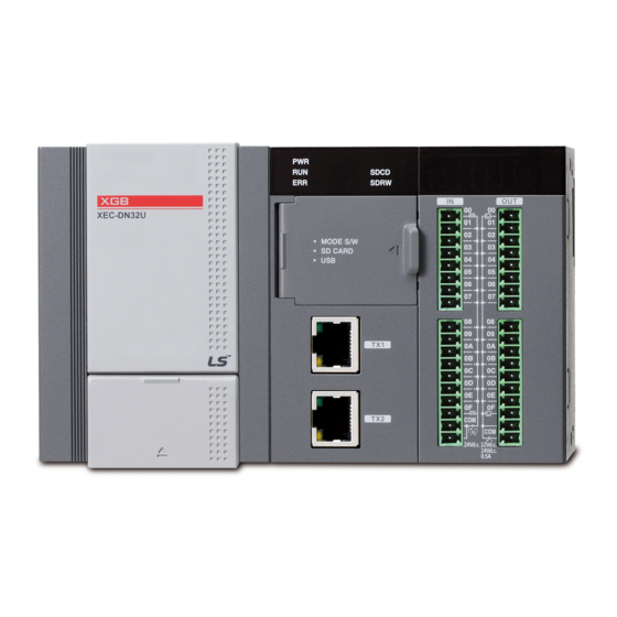
Chapter 3 Specifications Chapter 3 Specifications 3.1 Names and Functions of Each Part 3.1.1 Basic Type ⑫ ⑥ ① ⑤ ⑦ XBC-DN32U ② ⑧ ③ ④ ⑩ ⑪ ⑨ Names Purposes ① LED for displaying input, output ■ Displays the On/Off status of input, output contacts ■... - Page 47 Chapter 2 System Configuration ■ Terminal block(lower part of the product) for the embedded RS-232C/485 Terminal block for the ⑨ embedded communication communication ■ Terminal block (AC 100 ~ 240V) for power supply ⑩ Power terminal block ■ Terminal block with DC 24V output ⑪...
- Page 48 Chapter 3 Specifications embedded Enet communication ■ Terminal block(lower part of the product) for the embedded RS-232C/485 Terminal block for the ⑨ embedded communication communication ■ Terminal block (AC 100 ~ 240V) for power supply ⑩ Power terminal block ■ Terminal block with DC 24V output ⑪...
- Page 49 Chapter 2 System Configuration 3.1.3 Positioning Type ⑫ ⑥ ① ⑬ ⑤ ⑦ ② ⑧ ③ ④ ⑭ ⑮ ⑩ ⑪ ⑨ Names Purposes LED for displaying input, ■ Displays the On/Off status of input, output contacts output ■ Connector(USB 1channel) to access to XG5000 ②...
- Page 50 Chapter 3 Specifications ■Displays the operation status by positioning axes. LED displaying axial • Green light On: During the corresponding axial operation ⑬ operation • Green light Off: Stop of the corresponding axial operation • Flickering red light: Occurrence of errors from the corresponding axial operation ■...
-
Page 51: General Specifications
• Peak acceleration : 147 m/s (15G) • Duration : 11ms Shocks • Pulse wave type : Half-sine (3 times each direction per each axis) AC: ±1,500 V Square wave LSIS standard DC: ±900 V impulse noise Electrostatic IEC61131-2 Voltage: 4kV (Contact discharge) discharge... -
Page 52: Power Specifications
Chapter 3 Specifications 3.3 Power specifications This section describes the high performance XGB PLC basic unit’s power specifications. Items Specification Note Input volatage AC85V ~ AC264V range Rated input AC100V ~ AC240V voltage 50/60 ± 3 ㎐(47 ~ 63 ㎐) Input frequency 1.2A or less (AC110V, max load) - Page 53 Chapter 2 System Configuration 3.3.1 Consumption current (Unit : ㎃) Consumption current Type Model XEC-DN32U XEC-DR28U XEC-DN32UP 1250 Main unit XEC-DR28UP 1550 XEC-DN32UA XEC-DR28UA 1040 XBE-DC32A XBE-DC16A/B XBE-DC08A XBE-RY16A Expansion I/O module XBE-RY08A/B XBE-TN32/16/08A 80/50/40 XBE-DR16A XBE-TP32/16/08A 80/50/40 XBF-AD04A XBF-AD08A...
- Page 54 Consumption of current/voltage is calculated as follows. Internal 5V consumption Type Model Unit No. Remark current (Unit : ㎃) Main unit XEC-DN32U In case all contact points are On. XBE-DC32A (Maximum consumption current) XBE-TN32A Expansion module XBF-AD04A All channel is used. XBF-DC04A (Maximum consumption current)
-
Page 55: Battery
Chapter 2 System Configuration 3.4 Battery 3.4.1 Battery specifications Items Specifications Nominal voltage / current DC 3.6V / 800 mAh Warranty term 3 years(at room temperature) Purpose Program and data backup, RTC operation during the blackout Backup time 3years Specifications Lithium battery, 3.6V φ14.5 X 26 mm Appearance Size (mm) - Page 56 Chapter 3 Specifications 3.4.3 How to replace a battery The battery used for backup in case of power failure of programs and data requires the periodic replacement. Although the battery is removed, the program and data electrostatic holding data are maintained by the Super Capacitor for about 30 minutes, however, it should be replaced as soon as possible.
-
Page 57: Performance Specifications
Chapter 2 System Configuration 3.5 Performance specifications 3.5.1 Common performance specifications for CPU The high performance XGB basic unit’s common performance specifications for CPU are as below. Specifications Items XEC- XEC- XEC- XEC- XEC- XEC- Remark DN32U DR28U DN32UA DR28UA DN32UP DR28UP Cyclic execution of stored program, Time-driven interrupt,... - Page 58 Chapter 3 Specifications Internal device task Max 16 High Speed Max 8 Counter task Operation mode RUN, STOP, DEBUG Self-diagnosis function Detects errors of scan time, memory, I/O and power supply Program port USB 1 channel Back-up method Latch area setting in basic parameter Internal consumption current 700㎃...
- Page 59 Chapter 2 System Configuration 1-phase : 100 ㎑ 8 channels Performance 2-phase : 50 ㎑ 4 channels 4 counter modes are supported based on input pulse and INC/DEC method • 1 pulse operation Mode : INC/DEC count by program Counter •...
- Page 60 Chapter 3 Specifications 3.5.3 Specifications for Embeded Analog The specifications for Embeded Anlalog are as below. Items Specifications Remark Channels 4channels (current/voltage) Voltage: 1~5V, 0~5V, 0~10V, -10~10V Current: 4~20㎃,0~20㎃ Input Range Current input or Voltage input can be selected through the external terminal wiring setting.
-
Page 61: Chapter 4 Installation And Wiring
Chapter 4 Installation and wiring Chapter 4 Installation and wiring 4.1 Parameter & Operation data Danger Please design protection circuit at the external of PLC for entire system to operate safely because an abnormal output or an malfunction may cause accident when any error of external power or malfunction of PLC module. (1) It should be installed at the external side of PLC to emergency stop circuit, protection circuit, interlock circuit of opposition action such as forward /reverse operation and interlock circuit for protecting machine damage such as upper/lower limit of positioning. - Page 62 Chapter 4 Installation and wiring Danger Don’t close the control line or communication cable to main circuit or power line. Distance should be more than 100mm. It may cause malfunction by noise. In case of controlling lamp load, heater, solenoid valve, etc. in case of Off -> On, large current (10 times of normal current) may flows, so consider changing the module to module that has margin at rated current.
- Page 63 Chapter 4 Installation and wiring 4.1.1 fail safe circuit (1) example of system design (When ERR contact point of power module is not used) In case of AC In case of AC . DC Power Power Trans Trans Trans Fuse Fuse Fuse DC power...
- Page 64 Chapter 4 Installation and wiring (2) Fail Safe Measures in case of PLC failures Failures of the PLC CPU and memory are detected by self-diagnosis but if there are some problems with I/O control part, etc, the failure may not be detected from the CPU. In this case, it can be different depending on the failure status, all contacts may be On or Off so normal operation or safety of the controlled subject cannot be guaranteed.
- Page 65 Chapter 4 Installation and wiring 4.1.2 PLC heat calculation (1) Power consumption of each part (a) Power consumption of module The power conversion efficiency of power module is about 70% and the other 30% is gone with heat; 3/7 of the output power is the pure power consumption.
- Page 66 Chapter 4 Installation and wiring (e) Input average power consumption of input module (power consumption of simultaneous On point) • W X E X input point X simultaneous On rate (W) : input current (root mean square value in case of AC) (A) E : input voltage (actually used voltage) (V) (f) Power consumption of special module power assembly •...
-
Page 67: Attachment/Detachment Of Modules
Chapter 4 Installation and wiring 4.2 Attachment/Detachment of Modules 4.2.1 Attachment/Detachment of modules Caution in handling Use PLC in the range of general specification specified by manual. In case of usage out of range, it may cause electric shock, fire, malfunction, damage of product. Remark ... - Page 68 Chapter 4 Installation and wiring (2) Detachment of module • Get up the hook for fixation of upper part and lower part and disconnect it. • Detach the module with two hands. (Do not apply excessive force) Hook for module fixation Remark ...
- Page 69 Chapter 4 Installation and wiring (3) Installation of module XGB PLC has a hook for DIN rail (rail width: 35mm) so that cab be installed at DIN rail. (a) In case of installing at DIN rail • Pull the hook as shown below for DIN rail at the bottom of module and install it at DIN rail •...
- Page 70 Chapter 4 Installation and wiring (4) Module equipment location Keep the following distance between module and structure or part for ventilation, easy detachment and attachment. 30㎜ or above 20㎜or above 30㎜or above 5㎜ or above 5㎜ or above *1 : In case height of wiring duct is less than 50 mm (except this 40mm or more) *2 : In case of equipping cable without removing near module, 20mm or more *3 : In case of connector type, 20mm or above (5) Module equipment direction...
- Page 71 Chapter 4 Installation and wiring (6) Distance with other device To avoid radiation noise or heat, keep the distance between PLC and device (connector and relay) as far as the following figure. Device installed in front of PLC: 100 ㎜ or more Device installed beside PLC: 50 ㎜...
- Page 72 Chapter 4 Installation and wiring 4.2.2 Caution in handling Here describes caution from open to install • Don’t drop or impact product. • Don’t disassemble the PCB from case. It may cause an error. • In case of wiring, make sure foreign substance not to enter upper part of module.
-
Page 73: Wire
Chapter 4 Installation and wiring 4.3 Wire In case using system, it describes caution about wiring. Danger When wiring, cut off the external power. If all power is cut, it may cause electric shock or damage of product. In case of flowing electric or testing after wiring, equip terminal cover included in product. It not, it may cause electric shock. Remark ... - Page 74 Chapter 4 Installation and wiring (3) Isolate the PLC power, I/O devices and power devices as follows. Main unit Main power power Constant AC220V Voltage Transformer AC100-240V IO power Main circuit device (4) If using DC24V of the main unit (a) Do not connect DC24V of several power modules in parallel.
- Page 75 Chapter 4 Installation and wiring (8) When noise penetration coure use an insulated shielding transformer or noise filter. (9) Wiring of each input power should be twisted as short as possible and the wiring of shielding transformer or noise filter should not be arranged via a duct.
- Page 76 Chapter 4 Installation and wiring 4.3.2 I/O Device wiring (1) The size of I/O device cable is limited to 0.3~2 mm but it is recommended to select a size(0.3 mm ) to use conveniently. (2) Please isolate input signal line from output signal line. (3) I/O signal lines should be wired 100mm and more away from high voltage/high current main circuit cable.
- Page 77 Chapter 4 Installation and wiring (6) Example of input module. External Load (7) Example of output module. External Load 4-17...
- Page 78 Chapter 4 Installation and wiring 4.3.3 Grounding wiring (1) The PLC contains a proper noise measure, so it can be used without any separate grounding if there is a large noise. However, if grounding is required, please refer to the followings. (2) For grounding, please make sure to use the exclusive grounding.
-
Page 79: Chapter 5 Maintenance
Chapter 5 Maintenance Chapter 5 Maintenance Be sure to perform daily and periodic maintenance and inspection in order to maintain the PLC in the best conditions. 5.1 Maintenance and Inspection The I/O module mainly consist of semiconductor devices and its service life is semi-permanent. However, periodic inspection is requested for ambient environment may cause damage to the devices. -
Page 80: Daily Inspection
Chapter 5 Installation and wiring 5.2 Daily Inspection The following table shows the inspection and items which are to be checked daily. Corrective Check Items Check Points Judgment Actions Connection conditions of Retighten Check the screws. Screws should not be loose. base Screws. -
Page 81: Chapter 6 Troubleshooting
Chapter 6 Troubleshooting Chapter 6 Troubleshooting The following explains contents, diagnosis and corrective actions for various errors that can occur during system operation. 6.1 Basic Procedure of Troubleshooting System reliability not only depends on reliable equipment but also on short downtimes in the event of fault. The short discovery and corrective action are needed for speedy operation of system. - Page 82 Chapter 6 Trouble Shooting 6.2.1 Troubleshooting flowchart used when the PWR (Power) LED turns Off The following flowchart explains corrective action procedure used when the power is supplied or the power LED turns Off during operation. Power LED is turned Off. Is the power supply Supply the power.
- Page 83 Chapter 6 Troubleshooting 6.2.2 Troubleshooting flowchart used with when the ERR (Error) LED is flickering The following flowchart explains corrective action procedure used when the power is supplied starts or the ERR LED is flickering during operation. STOP LED goes flickering Check error code,...
- Page 84 Chapter 6 Trouble Shooting 6.2.3 Troubleshooting flowchart used with when the RUN , STOP LED turns Off. The following flowchart explains corrective action procedure to treat the lights-out of RUN LED when the power is supplied, operation starts or is in the process. RUN, STOP LED is Off.
- Page 85 Chapter 6 Troubleshooting 6.2.4 Troubleshooting flowchart used when the I/O part doesn’t operate normally. The following flowchart explains corrective action procedure used when the I/O module doesn’t operate normally. When the I/O module doesn’t work normally. Is the output LED of SOL1 Replace the connector of Correct wiring.
- Page 86 Chapter 6 Trouble Shooting Continue Are the indicator LED of the switch 1 and 2 on? Check voltage of switch 1,2 by Check voltage of switch 1,2 by tester tester Is the Is the measured value Is the measured value terminal screw tighten normal? normal?
-
Page 87: Troubleshooting Questionnaire
Chapter 6 Troubleshooting 6.3 Troubleshooting Questionnaire If any problem occurs during the operation of XGB series, please write down this Questionnaires and contact the service center via telephone or facsimile. For errors relating to special or communication modules, use the questionnaire included in the User’s manual of the unit. 1. -
Page 88: Troubleshooting Examples
Chapter 6 Trouble Shooting 6.4 Troubleshooting Examples Possible troubles with various circuits and their corrective actions are explained. 6.4.1 Input circuit troubles and corrective actions The followings describe possible troubles with input circuits, as well as corrective actions. Corrective Actions Cause Condition ... - Page 89 Chapter 6 Troubleshooting Use only one power supply. Sneak current due to the use of two different power Connect a sneak current prevention diode. Input signal doesn’t turn off. supplies. DC input DC input E1 > E2, sneaked. 6.4.2 Output circuit and corrective actions The following describes possible troubles with output circuits, as well as their corrective actions.
- Page 90 Chapter 6 Trouble Shooting Leakage current by surge absorbing circuit, which is Drive the relay using a contact and drive the C-R type When the load is C-R type timer, connected to output element in parallel. timer using the since contact. ...
- Page 91 Chapter 6 Troubleshooting transistor output. To suppress the surge current make the dark Output Surge current of the white lamp on. transistor current of 1/3 to 1/5 rated current flow. destroyed. Output Output Sink type transistor output Output A surge current of 10 times or more when turned Source type transistor...
-
Page 92: Error Code List
Chapter 6 Trouble Shooting 6.5 Error Code List Error code Action Operation Diagnosis Error cause (restart mode after taking an action) status status point (Dec) Program to execute is 0.5 second Start after reloading the program Warning RUN mode abnormal Flicker Start after reloading I/O parameter, Reset... - Page 93 Chapter 6 Troubleshooting Error code Action Operation Diagnosis Error cause (restart mode after taking an action) status status point (Dec) Scan time of program during operation After checking the scan watchdog time designated While exceeds the scan 0.5 second by parameter, modify the parameter or the Warning running the watchdog time...
-
Page 94: Chapter 7 Emc Standard
XGB series. The details of these precautions are based on the requirements and the applicable standards control. However, LSIS will not guarantee that the overall machinery manufactured according to the these details conforms to the below-described directives. The method of conformance to the EMC directive and the judgment on whether or not the machinery conforms to the EMC Directive must be determined finally by the manufacturer of the machinery. - Page 95 Chapter 7 EMC Standard 7.1.2 Control Panel The PLC is an open type device (device installed to another device) and must be installed in a control panel. This is needed to prevent electric shock by touching XGB PLC and reduce the PLC-generated noise. Install the XGB PLC in a metallic panel to reduce PLC-generated EMI (Electro-magnetic interference), The specifications for the control panel are as follows: (1) Control panel...
- Page 96 Chapter 7 EMC Standard (2) Connection of power and earth wires Earthing and power supply wires for the PLC system must be connected as described below. ferrite core (a) Earth the control panel with a thick wire so that a low impedance connection to ground can be ensured even at high frequencies. (b) The function of LG (Line Ground) and FG (Frame Ground) terminals is to pass the noise generated in the PLC system to the ground, so an impedance that is as low as possible must be ensured.
-
Page 97: Requirement To Conform To The Low-Voltage Directive
The described contents in this manual are based on the requirements and the applicable standards control. However, LSIS will not guarantee that the overall machinery manufactured according to the these details conforms to the above regulation. The method of conformance to the EMC directive and the judgment on whether or not the machinery conforms to the EMC Directive must be determined finally by the manufacturer of the machinery. -
Page 98: Part2. Basic Functions
Chapter 1 Configuration and Operation Mode of Programs Part 2 Basic Functions This Chapter covers the details of programming and operations, monitoring of the high performance XGB basic unit (XBC-DN32UX) Chapter 1 Program Configuration and Operation Method 1.1 Programming Basics 1.1.1 Programming Method The XBC high performance basic unit supports programming method of repetitive operation interrupt operation, fixed operation. - Page 99 Chapter 1 Configuration and Operation Mode of Programs (2) Interrupt operation mode (fixed cycle, external interrupt, internal device start, high speed counter) It is the mode that suspends the currently executed scan program operation and handles the interrupt program immediately when urgent priority matter occurs during execution of the PLC scan program. The signals that inform the CPU of such interrupt occurrence is called ‘interrupt signal’...
- Page 100 Chapter 1 Configuration and Operation Mode of Programs 1.1.2 Execution processing in case of instantaneous interruption If the input power voltage supplied to XGB basic unit is lower than the specification, the PLC will detect instantaneous interruption. When the PLC detects instantaneous interruption, the following execution processing will run. Blackout time Execution processing (1) Execution is interrupted, maintaining output state of when...
- Page 101 Chapter 1 Configuration and Operation Mode of Programs 1.1.3 Scan Time The scan time is the time that takes to complete a single control operation from step 0 of the full scan program to step 0 of the next scan; it is directly connected to the system’s control performance. (1) Scan time formula The scan time is the sum of the process time of the scan program and interrupt program written by a user and the PLC’s internal END processing time;...
- Page 102 Items Basic unit SLOT2 SLOT3 SLOT4 SLOT5 SLOT6 SLOT7 SLOT8 Product XBL- XEC-DN32U XBE-DC32A * 3EA XBF-AD04A * 2EA XBL-EMTA name C41A Operating 200 Byte per module, 32kStep conditions 1 block Scan time= Ladder running time + system processing time + digital I/O processing time + analog I/O processing time + communication module processing time + XG5000 Service processing time = 9.7 + 0.8 + 0.3*3 + 2.0*2 + 0.8*2 +0.1㎲...
- Page 103 Chapter 1 Configuration and Operation Mode of Programs WORD Flag Name Name Description Maximum scan The longest scan time (update in case of occurrence only), in %FW50 _SCAN_MAX time 0.1ms The shortest scan time (update in case of occurrence only), in %FW51 _SCAN_MIX Minimum scan time...
- Page 104 Chapter 1 Configuration and Operation Mode of Programs 1.1.5 Interrupt (1) Interrupt processing flow chart It describes the PLC’s operation flow chart, giving you the example of setting the interrupt program as below. • Interrupt setting Interrupt type Interrupt Name Priority Task No.
- Page 105 Chapter 1 Configuration and Operation Mode of Programs (2) Types and operation standards of tasks The types and operation standards of tasks that are available for the high performance small-sized PLC are as below. Type Fixed cycle task External contact task Internal contact task High speed counter task Spec.
- Page 106 Chapter 1 Configuration and Operation Mode of Programs (d) Relation between the initialization, scan program and the task program When executing the initialization task program, the fixed cycle, external contact, high speed counter, internal contact task cannot be started. The scan program has the lowest priority so when the task occurs, the scan program will be suspended and the task program will be executed preemptively.
- Page 107 Chapter 1 Configuration and Operation Mode of Programs (5)Example of program configuration and processing The example of the program execution sequence is given under the registered tasks and programs as below. • Registered task programs Interrupt source Interrupt Name Priority Task No.
- Page 108 Chapter 1 Configuration and Operation Mode of Programs time (㎳) Executed details 25~30 The program 2 runs. The request on 10㎳_fixed cycle interrupt occurs and the 10㎳_fixed cycle has higher priority so the 30~32 program 2 is interrupted and the program 1 runs. 32~34 The execution of the program 1 is completed and the program 2 that was interrupted is finished.
- Page 109 Chapter 1 Configuration and Operation Mode of Programs (c) Click on the right mouse button on the registered task and click 『Add Items』-『Program』. (d) Make the necessary initialization program and make sure to include the INIT_DONE command to the initialization task program. (If the operation conditions of INIT_DONE runs, the initialization task is ended and the scan program runs.) 1-12...
- Page 110 Chapter 1 Configuration and Operation Mode of Programs 1.1.7 Fixed cycle task (1) How to set up the task (a) Adding tasks: Select 『Project』–『Add Items』–『Task』 or after clicking with the right mouse button on the project name of the project tree, select 『Add Items』-『Task』 as shown in the below figure. (b) The screen for registering the task will be displayed.
- Page 111 Chapter 1 Configuration and Operation Mode of Programs (c) Click on the right mouse button on the registered task and click 『Add Items』-『Program』. (d) Register the task program name and comment. (e) If the program window for writing the task program is displayed, you can make the task program here. 1-14...
- Page 112 Chapter 1 Configuration and Operation Mode of Programs (2) Instructions to use the fixed cycle task The corresponding task program with fixed cycle runs at every set time interval (running cycle) and keep the below instructions in mind. • When the specific task program with the fixed cycle runs currently or stands by for execution, if the request on running the same task program occurs, the newly occurred task will be ignored.
- Page 113 Chapter 1 Configuration and Operation Mode of Programs (b) The screen for registering the task will be displayed. Click 『External contact』in the execution conditions and after entering the task name, input the items required for setting as below. Items Input range Description Priority Designates the priority of tasks.
- Page 114 Chapter 1 Configuration and Operation Mode of Programs (d) Register the task program name and comment. (e) If the program window for writing the task program is displayed, you can make the task program here. (3) Instructions to use the external contact task When the rising, falling or transition conditions occur in the set input contact, the corresponding external contact task program runs and keep the below instructions in mind.
- Page 115 Chapter 1 Configuration and Operation Mode of Programs 1.1.9 Internal device task (1) How to set up the task (a) Adding tasks: Select 『Project』–『Add Items』–『Task』 or after clicking with the right mouse button on the project name of the project tree, select 『Add Items』-『Task』 as shown in the below figure. (b) The screen for registering the task will be displayed.
- Page 116 Chapter 1 Configuration and Operation Mode of Programs (c) Click on the right mouse button on the registered task and click 『Add Items』-『Program』. (d) Register the task program name and comment. 1-19...
- Page 117 Chapter 1 Configuration and Operation Mode of Programs (e) If the program window for writing the task program is displayed, you can make the task program here. (2) Instructions to use the internal device task The internal contact task detects the startup conditions of the internal device set by the scan END and runs the relevant internal device task program.
- Page 118 Chapter 1 Configuration and Operation Mode of Programs 1.1.10 High speed counter task (1) How to set up the task (a) Adding tasks: Select 『Project』–『Add Items』–『Task』 or after clicking with the right mouse button on the project name of the project tree, select 『Add Items』-『Task』 as shown in the below figure. (b) The screen for registering the task will be displayed.
- Page 119 Chapter 1 Configuration and Operation Mode of Programs (c) Click on the right mouse button on the registered task and click 『Add Items』-『Program』. (d) Register the task program name and comment. (e) If the program window for writing the task program is displayed, you can make the task program here. (2) Instructions to use the high speed counter task •...
-
Page 120: Operation Mode
Chapter 1 Configuration and Operation Mode of Programs 1.2 Operation mode The high performance XGB PLC has 3 operation modes; RUN mode, STOP mode, DEBUG mode. This section describes the execution processing of each operation mode. 1.2.1 RUN mode It is the mode executing the program normally. (1) When changing the mode from other into RUN Initialize the data area at the beginning stage and check the validity of the program to determine whether it can be executed or not. - Page 121 Chapter 1 Configuration and Operation Mode of Programs (c) Communication services are executed with other internal processing. 1.2.2 STOP Mode It is the mode of block state without operations of the program. In STOP mode, you can write the programs and parameters through XG5000.
- Page 122 Chapter 1 Configuration and Operation Mode of Programs 1.2.4 Change of operation modes (1) How to change operation modes You can change the operation mode with the below methods. (a) Change by the mode key of the basic unit (b) Change by connecting the programming tool (XG5000) to the PLC (c) Changing the operation mode of the other basic unit connected to network with XG5000 accessed to the basic unit 1 (remote access) (d) Change by using XG5000, HMI, communication module connected to the network...
-
Page 123: Memory
Chapter 1 Configuration and Operation Mode of Programs 1.3 Memory The high performance XGB basic unit has two types of memory for a user. One is the program memory saving the user program that is made by a user to build up the system; another is the data memory providing the device area that saves the data during operation. - Page 124 Chapter 1 Configuration and Operation Mode of Programs (1) Memory block diagram 1-27...
- Page 125 Chapter 1 Configuration and Operation Mode of Programs 1.3.3 Data retain area setting In case you want to keep the data necessary for operation and the data made during operation when PLC stops and restarts, Default(automatic) Variable Retain is used and some area of M area can be set as Retain area through parameter setting The following is characteristic table about the device available for Retain setting Retain Device...
- Page 126 Chapter 1 Configuration and Operation Mode of Programs For holding of retain area data or reset (clear) operation according to PLC operation, refer to the following table. Classification Retain M area Retain R area Reset Hold previous value Hold previous value Hold previous value Overall reset Initialized as ‘0’...
-
Page 127: Chapter 2 Cpu Function
Chapter 2 CPU Function Chapter 2 CPU Function 2.1 Type Setting This section descries setting XGB PLC models. CPU Type Language Description Remarks Name Economic : XEC-R10/14/20/30E XGB-XECE IEC language XEC-DN10/14/20/30E, Compact type XE-DP10/14/20/30E Deluxe: XEC-DR32/64H, XEC-DN32/64H XGB-XECH IEC language Compact type XEC-DP32/64H Standard : XE-DR20/30/40/60SU,... -
Page 128: Parameter Setting
Chapter 2 CPU Function 2.2 Parameter Setting This section describes XGB PLC’s parameter setting. 2.2.1 Basic parameter setting If you click the basic parameter in the project window, the below screen will be displayed. You can set up 3 items; ‘Basic operation setting’, ‘Device area setting’, ‘Error operation setting’. Classification Items Descriptions... - Page 129 Chapter 2 CPU Function 2.2.2 I/O parameters Setting It is the function to set up and reserve the information for each I/O. If you click 『I/O Parameter』in the project window, the below setting window will be displayed. If you click the 『Module』in the 『slot』 position, the list of each module will be displayed. Then, choose the module that is matched with the actual system to be configured.
- Page 130 Chapter 2 CPU Function If you press 『In Detail』button on the slot image or the relevant slot position in the base window as below, the window for setting the filter, emergency output will be displayed. Notice • In case each set details are different from the actually accessed I/O module, ‘Module Type Mismatch Error’ occur and the error will be displayed.
-
Page 131: Self-Diagnosis Function
Chapter 2 CPU Function 2.3 Self-Diagnosis Function The Self-Diagnosis function is the function for the CPU part to diagnose the PLC system for defects. In case errors occur during supplying the power to the PLC system or during operation, it detects errors to prevent malfunction of the system and preventive maintenance. - Page 132 Chapter 2 CPU Function 2.3.2 Function to save error history When errors occur, the high performance XGB basic unit records the error history to clean up causes easily. If you click 『Online』-『Error/Warning』, you can see the current errors and the history. Remove the causes of errors referring to the details and corrective measures of each error item.
- Page 133 Chapter 2 CPU Function (2) Operation mode in case of failures In case failures occur, the PLC system records the failure details in the special flag (F area) and determines whether resuming the operation based on the failure mode. • In case of the PLC hardware’s failure In case there are problems with the CPU, power, etc.
- Page 134 Chapter 2 CPU Function %FX44 _PGM_ER Program error There are some errors with the program. There are some errors with the program %FX45 _CODE_ER Code error code. %FX46 _SWDT_ER System Watch dog The system Watchdog works. %FX48 _WDT_ER Scan Watch dog The scan Watchdog works.
- Page 135 Chapter 2 CPU Function Information on the Displays the information on the external %FW202 _ANC_ERR external device’s device’s failure failure Information on the Displays the information on the external %FW203 _ANC_WAR external device’s minor device’s minor failure failure Notice • For more details on the whole flags, refer to the Appendix 1 Flag Table of the Outline of this manual. 2.3.4 Function to check the battery voltage It is the function to detect and inform the fact that the battery voltage is lower than the memory backup voltage.
- Page 136 Chapter 2 CPU Function (3) How to detect the external device’s serious failures The following programming is used to detect the external device’s serious failures. (a) Save the error code that can be distinguished by external device’s serious failures in %FW202 (_ANC_ERR) through the MOVE command as below.
- Page 137 Chapter 2 CPU Function - When the device 1 is disconnected, %IX0.5.2 is ON. The error code is the value saved in _device1 disconnected. • In the above programming, when %IX0.5.0 is On (In case of sensor failure), the value of D000 is saved in %FW202 (_ANC_ERR) and%FX3202 (_CHK_ANC_ERR) will be On.
- Page 138 Chapter 2 CPU Function < Example of the system configuration and program > • In this example, assume that the input signal to detect the external device’s minor failures is connected to the input module of No.5 slot in the system configuration as below. - In case of the sensor warning, %IX0.5.0 is ON.
-
Page 139: Rtc Function
Chapter 2 CPU Function 2.4 RTC Function The high-performance XGB basic unit has the embedded clock (RTC) function that keeps running by battery backup even when the power is off. The time data of the embedded RTC can be used for time management such as the system’s operating history or failure history, etc. - Page 140 Chapter 2 CPU Function (c) Example of modifying clock data through the program A user can set up the clock data through the program using RTC-SET function blocks as below. Function block I/O variable Description It executes the function block in rising edge. DATA Time data to input (Refer to the below table.) DONE...
-
Page 141: Remote Functions
Chapter 2 CPU Function 2.5 Remote Function In the high performance XGB basic unit, you can change the operation mode through the key switch attached to the module or through communication. For remote operation, put the basic unit’s mode change switch on STOP position. (1) The kinds of remote operations are as below. -
Page 142: I/O Forced On/Off Functions
Chapter 2 CPU Function 2.6 I/O forced On/Off Functions The forced I/O function is used to turn On/Off I/O areas by force regardless of the results of program execution. 2.6.1 Forced I/O setting method Click『Online』-『 Forced I/O setting 』. The below table represents the items related to the forced I/O setting. Item Description Remarks... -
Page 143: Direct I/O Operation Function
Chapter 2 CPU Function forced set data, and then, they are output. Accordingly, in contrast with the forced input, in the case of the forced output, the data of the output image area shows the same data with the program operation results but the actual output changes by the forced output On/Off settings. - Page 144 Chapter 2 CPU Function (1) Input base number 0 and slot number 4 where output module is equipped (2) Since data to output is 16 bit during scan, enable lower 16 bit among value of MASK_L (16#FFFF0000) (3) If execution condition (%IX0.0.0) is On, DIREC_O (Immediate refresh of output module) is executed and data of output module is set as 2#0111_0111_0111_0111.
-
Page 145: Function Saving The Operation History
Chapter 2 CPU Function 2.8 Function saving the operation history There are 4 types of operation history; error history, mode conversion history, power down history and system history. The occurrence time, frequency, operating details of each event are saved in the memory and you can conveniently monitor the data through XG5000. -
Page 146: How To Allocate I/O No
Example of allocating I/O No. based on the system configuration Slot No. Model I/O allocation Remakrs input : %IX0.0.0 ~ %IX0.0.63 Actua linput : %IX0.0.0 ~ %IX0.0.15 XEC-DN32U output : %QX0.0.0 ~ %QX0.0.63 Actual output : %QX0.0.0 ~ %QX0.0.15 Embedded special input : %IX0.1.0 ~ %IX0.1.63 functions output : %QX0.1.0 ~ %QX0.1.63... -
Page 147: Program Modification During Operation (Modification During Run)
Chapter 2 CPU Function 2.10 Program Modification during operation (Modification during RUN) You can modify the programs and communication parameters without stopping control operations during running the PLC. The below describes the basic modification method. For more details on Modification during RUN, refer to the XG5000 manual. - Page 148 Chapter 2 CPU Function (3) Then, the background color of the program window changes and it is converted into the mode of modification during RUN. (4) You can modify the program. (5) When the modification of the program is completed, click 『Online』-『Write Modification During RUN』 2-22...
- Page 149 Chapter 2 CPU Function (6) When Write Program is completed, click 『Online』-『End Modification During RUN』. (7) The background color of the program window changes into the original one and modification during RUN is completed. Notice • For Modification of communication parameters during RUN, after changing the network configuration items of XG5000 in the RUN status without going into the Modification during RUN menu, click 『Online』-『Write』...
-
Page 150: Read I/O Information
Chapter 2 CPU Function 2.11 Read I/O information It is the function to monitor each module’s information comprising the XGB PLC system. (1) If you click 『Online』-『I/O Information』, the information of each module of connected systems will be monitored. (2) If you click ‘Detailed Information’ after choosing the module, the details on the module will be displayed. 2-24... - Page 151 Chapter 2 CPU Function 2.12 Monitoring Functions It is the function to monitor the XGB PLC system’s general information. (1) If you click 『Monitor』, the submenu will be displayed as below. (2) The below table provides the descriptions on each item. Items Descriptions Remarks...
- Page 152 Chapter 2 CPU Function (b) Device monitor It is the monitoring function by device. (c) Monitor suspension setting It is the function to stop monitoring when the set device value is matched. (d) Trend Monitor It is the function to represent the set device value in a graphic form. The value represented on the graph is not the data collected by the PLC at the right timing but the value read from XG5000 through the communication function.
- Page 153 Chapter 2 CPU Function (e) Custom event 1) It is the function to monitor the detailed information when the event set by a user occurs. Register the user event additionally. 2-27...
- Page 154 Chapter 2 CPU Function 2) Establish the basic settings and related device. In case the rising edge of %Mx0 device occur, the Alarm message “Tank 1 Error-> Please Confirm” is recorded with the then values of %MW100 and “DATA”. 3) Set up the associated device. 4) It monitors the user event history.
- Page 155 Chapter 2 CPU Function Notice • For more details on the monitor, refer to the XG5000 manual. 2-29...
-
Page 156: Function To Delete All Of The Plc
Chapter 2 CPU Function 2.13 Function to delete all of the PLC The function to delete all of PLC is the initialization function to delete all programs, parameters, passwords, data stored in the PLC. (1) How to delete all of PLC (a) Click『Online』-『Delete all of PLC 』. -
Page 157: Chapter 3 Input/Output Specifications
Chapter 3 Input/Output Specifications Chapter 3 Input/Output Specifications 3.1 Introduction Here describes the notices when selecting digital I/O module used for XGB series. (1) For the type of digital input, there are two types such as current sink input and current source input. (2) The number of max. - Page 158 Chapter 3 Input/Output Specification (7) Relay life of Relay output module is shown as below. Max. life of Relay used in Relay output module is shown as below. AC 125V Resistive load DC 30V Resistive load AC 250V Resistive load Open/Close current (A)
- Page 159 Chapter 3 Input/Output Specifications (8) A clamped terminal with sleeve can not be used for the XGB terminal strip. The clamped terminals suitable for terminal strip are as follows (JOR 1.25-3:Daedong Electricity in Korea). 6.0mm or less 6.0mm or less (9) The cable size connected to a terminal strip should be 0.3~0.75 ㎟...
- Page 160 Chapter 3 Input/Output Specification (a) Setting input filter 1) Click I/O Parameter』in the project window of XG5000 2) Click『Module』 at the slot location.
- Page 161 Chapter 3 Input/Output Specifications 3) Set I/O module really equipped. 4) After setting I/O module, click Input Filter.
- Page 162 Chapter 3 Input/Output Specification 5) Set filter value. (b) Setting output status in case of error 1) Click Emergency Out in the I/O parameter setting window.
- Page 163 Chapter 3 Input/Output Specifications 2) Click Emergency Output. If it is selected as Clear, the output will be Off and if Hold is selected, the output will be kept.
-
Page 164: Main Unit Digital Input Specifications
Chapter 3 Input/Output Specification 3.2 Main Unit Digital Input Specifications 3.2.1 XEC-DN32U 16 point DC24V input Model Main unit XEC-DN32U/XEC-DN32UP/XEC-DN32UA Specification XEC-DR28U/XEC-DR28UP/XEC-DR28UA 16 point Input point Photo coupler insulation Insulation method DC24V Rated input voltage About 4㎃ (Contact point 0~3: about 7㎃) Rated input current DC20.4~28.8V (within ripple rate 5%) -
Page 165: Main Unit Digital Output Specifications
Chapter 3 Input/Output Specifications 3.3 Main Unit Digital Output Specifications 3.3.1 XEC-DN32U 16 point transistor output (Sink type) Model Main unit Specification XEC-DN32U/XEC-DN32UP/XEC-DN32UA 16 point Output point Photo coupler insulation Insulation method DC 12/24V Rated load voltage Operation load voltage DC 10.2 ~ 26.4V... - Page 166 Chapter 3 Input/Output Specification 3.3.2 XEC-DR28U 12 point relay output Model Main unit Specification XEC-DR28U/XEC-DR28UA/XEC-DR28UP 16 point Output point Relay insulation Insulation method DC24V 2A (Resistive load) / AC220V 2A (COSΦ = 1), Rated load voltage/current 2A/COM(P20~23),5A/COM(P24~2B) DC5V / 1㎃ Min.
-
Page 167: Digital Input Specifications
Chapter 3 Input/Output Specifications 3.4 Digital Input Specifications 3.4.1 8 point DC24V input module (Source/Sink type) Model DC input module XBE-DC08A Specification 8 point Input point Photo coupler insulation Insulation method DC24V Rated input voltage About 4㎃ Rated input current DC20.4~28.8V (ripple rate <... - Page 168 Chapter 3 Input/Output Specification 3.4.2 16 point DC24V input module (Sink/Source type) Model DC input module Specification XBE-DC16A XBE-DC16B Input point 16 point Insulation method Photo coupler insulation Rated input voltage DC24V DC12/24V Rated input current About 4㎃ About 4/8㎃ DC20.4~28.8V Operation voltage range DC9.5~30V (ripple rate <...
- Page 169 Chapter 3 Input/Output Specifications 3.4.3 32 point DC24V input module (Source/Sink type) Model DC input module Specification XBE-DC32A 32 point Input point Photo coupler insulation Insulation method DC24V Rated input voltage About 4㎃ Rated input current DC20.4~28.8V (ripple rate < 5%) Operation voltage range Refer to Derating diagram Input Derating...
-
Page 170: Digital Output Specifications
Chapter 3 Input/Output Specification 3.5 Digital Output Specifications 3.5.1 8 point relay output module Model Relay output module Specification XBE-RY08A 8 point Output point Relay insulation Insulation method DC24V 2A (Resistive load) / AC220V 2A (COSΨ = 1), 5A/COM Rated load voltage / Current DC5V / 1㎃... - Page 171 Chapter 3 Input/Output Specifications 3.5.2 8 point relay output module (Independent point) Model Relay output module Specification XBE-RY08B 8 point Output point Relay insulation Insulation method DC24V 2A (Resistive load) / AC220V 2A (COSΨ = 1), 2A/COM Rated load voltage / Current DC5V / 1㎃...
- Page 172 Chapter 3 Input/Output Specification 3.5.3 16 point relay output module Model Relay output module Specification XBE-RY16A Output point 16 point Insulation method Relay insulation Rated load voltage/ current DC24V 2A (Resistive load) / AC220V 2A (COSΨ = 1), 5A/COM Min. load voltage/current DC5V / 1㎃...
- Page 173 Chapter 3 Input/Output Specifications 3.5.4 8 point transistor output module (Sink type) Model Transistor output module Specification XBE-TN08A Output point 8 point Insulation method Photo coupler insulation Rated load voltage DC 12 / 24V Load voltage range DC 10.2 ~ 26.4V Max.
- Page 174 Chapter 3 Input/Output Specification 3.5.5 16 point transistor output module (Sink type) Model Transistor output module Specification XBE-TN16A Output point 16 point Insulation method Photo coupler insulation Rated load voltage DC 12 / 24V Load voltage range DC 10.2 ~ 26.4V Max.
- Page 175 Chapter 3 Input/Output Specifications 3.5.6 32 point transistor output module (Sink type) Model Transistor output module Specification XBE-TN32A 32 point Output point Photo coupler insulation Insulation method DC 12 / 24V Rated load voltage DC 10.2 ~ 26.4V Load voltage range 0.2A / 1 point, 2A / 1COM Max.
- Page 176 Chapter 3 Input/Output Specification 3.5.7 8 point transistor output module (Source type) Model Transistor output module Specification XBE-TP08A 8 point Output point Photo coupler insulation Insulation method DC 12 / 24V Rated load voltage DC 10.2 ~ 26.4V Load voltage range 0.5A / 1 point Max.
- Page 177 Chapter 3 Input/Output Specifications 3.5.8 16 point transistor output module (Source type) Model Transistor output module Specification XBE-TP16A Output point 16 point Insulation method Photo coupler insulation Rated load voltage DC 12 / 24V Load voltage range DC 10.2 ~ 26.4V Max.
- Page 178 Chapter 3 Input/Output Specification 3.5.9 32 point transistor output module (Source type) Model Transistor output module Specification XBE-TP32A 32 point Output point Photo coupler insulation Insulation method DC 12 / 24V Rated load voltage DC 10.2 ~ 26.4V Load voltage range 0.2A / 1 point, 2A / 1COM Max.
-
Page 179: Combined Digital I/O Module Input Specification
Chapter 3 Input/Output Specifications 3.6 Combined Digital I/O module Input Specification 3.6.1 8 point DC24V input (Source/Sink type) Model DC input module Specification XBE-DR16A 8 point Input point Photo coupler insulation Insulation method DC24V Rated input voltage About 4㎃ Rated input current DC20.4~28.8V (within ripple rate 5%) Operation voltage range DC19V or higher / 3㎃... -
Page 180: Combined Digital I/O Module Output Specification
Chapter 3 Input/Output Specification 3.7 Combined Digital I/O module Output Specification 3.7.1 8 point relay output Model Relay output module Specification XBE-DR16A 8 point Output point Relay insulation Insulation method Rated load DC24V 2A (Resistive load) / AC220V 2A (COSΨ = 1), 5A/COM voltage / Current DC5V / 1㎃... -
Page 181: I/O Modules' Functions
Chapter 3 Input/Output Specifications 3.8 I/O modules’ Functions 3.8.1 Input filter function The XGB PLC’s input modules have the input filter function to prevent the external noise signal flowed into the input signal. For more details on the input filter function, refer to the below. (1) Purposes and Operations of the input filter function Under the environment with serious noise or in the case of the equipment that is greatly affected by the input signal’s pulse width, the system may receive incorrect input depending on the input signal status. - Page 182 Chapter 3 Input/Output Specification 3.8.2 Emergency output function The XGB PLC’s output module supports the emergency output function to determine whether maintaining the output status of the output module or clearing it when the PLC is stopped due to errors. You can set the emergency output by 8 points.
- Page 183 Chapter 3 Input/Output Specifications 3.8.3 Pulse Catch Function The XGB PLC basic unit has the input contacts (P0008 ~ P000F) for Pulse Catch with 8 points. Through these contacts, it is possible to receive the very short pulse signal that cannot be recognized by the normal digital input. (1) Purposes and Operations of the Pulse Catch function The PLC’s input data is refreshed in a lump once every scan.
- Page 184 Chapter 3 Input/Output Specification 2) Select [Main] in slot. 3) Select Module. 4)Double Click I/O Module. Select Pulse Catch output 3-28...
-
Page 185: Chapter 4 Built-In High-Speed Counter Function
Chapter 4 Built-in High-speed Counter Function Chapter 4 Built-in High-speed Counter Function XGB series have built-in function of High-speed counter in main unit. This chapter describes specifications and usage of High- speed counter’s function High-speed Counter Specifications 4.1.1 Performance Specifications (1) Performance specifications Classification Spcification... - Page 186 Chapter 4 Built-in High-speed Counter Function Classification Spcification Output points 2 point/channel (for each channel):use output contact point of main unit External Selects single-compared (>, >=, =, =<, <) or section-compared output (included or Type output excluded) (program setting) Output type Transistor output Count Enable To be set through program (count available only in enable status)
- Page 187 Chapter 4 Built-in High-speed Counter Function 4.1.2 Designation of Parts (1) Designation of parts Terminal Names Usage 1-phase 2-phase 1-phase 2-phase %IX0.0.0 Ch0 counter input Ch0 A-phase input counter input terminal A-phase input terminal %IX0.0.1 Ch1 counter input Ch0 B-phase input counter input terminal B-phase input terminal %IX0.0.2...
- Page 188 Chapter 4 Built-in High-speed Counter Function (2) Interface with external devices Signal Name On/Off Terminal Internal circuit Operation Guaranteed 1-phase 2-phase voltage 20.4~28.8V Ch 0 %IX0.0.0 pulse input A-phase input 4.7 kΩ 6V or less 20.4~28.8V Ch 1 Ch 0 %IX0.0.1 pulse input B-phase input...
- Page 189 Chapter 4 Built-in High-speed Counter Function 4.1.3 Functions of High-speed Counter (1) Counter mode (a) High Speed counter function can count High Speed pulses which can not be processed by CPU module’s counter instructions (CTU, CTD, CTUD, etc.), up to binary value of 32 bits (-2,147,483,648 ~ 2,147,483,647). (b) Available input is 1-phase input, 2-phase input and CW/ CCW input.
- Page 190 Chapter 4 Built-in High-speed Counter Function b) Increasing/decreasing count operation by B-phase input signal • 1-phase 2-input 1-multiplication operation mode A-phase input pulse counts at rising and increasing/decreasing will be decided by B-phase. A-phase input pulse rising A-phase input pulse falling Increasing/Decreasing classification B-phase input pulse Off Increasing count...
- Page 191 Chapter 4 Built-in High-speed Counter Function (2) Counter mode 2 types of count (Linear counter, Ring counter) can be selected for the applicable use based on functions. • Counter mode is saved at the following special K area. Area per each channel (word) Mode Ref.
- Page 192 Chapter 4 Built-in High-speed Counter Function (b) Ring count Set Ring Counter Min. Value and Max. value. Preset value and compared set value should be in range of ring counter min. value and max. value. Ring counter max. and min value is saved at the following special K area. Area per each channel (Double word) type Ref.
- Page 193 Chapter 4 Built-in High-speed Counter Function 2) During decreasing count Even if count value exceeds user-defined minimum value during decreasing count, Borrow only occurs and count does not stop differently to Linear Count. Count Ring count max value Count start Input pulse : Not included : Included...
- Page 194 Chapter 4 Built-in High-speed Counter Function 4) Operation when setting Ring Count based on present count value (during decreasing count) • If present count value exceeds user-defined range when setting Ring Count - Error (code no. 27) is occurred and it operates linear counter. If the present count value goes into the ring count range, it operates ring counter.(The error code is not cleared.) •...
- Page 195 Chapter 4 Built-in High-speed Counter Function (3) Compared output (a) High Speed counter module has a compared output function used to compare present count value with compared value in size to output as compared. (b) Available compared outputs are 2 for 1 channel, which can be used separately. (c) Compared output conditions are 7 associated with >, =, <...
- Page 196 Chapter 4 Built-in High-speed Counter Function • In order to output the compared output signal, compared output enable flag set to ‘1’ after compared output condition set. Area per channel Classification Operation Ch. 0 Ch. 1 Ch. 2 Ch. 3 Ch.
- Page 197 Chapter 4 Built-in High-speed Counter Function (e) Detail of comparator output It describes detail of comparator output (based on comparator output 0) 1) Mode 0 (Present value < Compared value) If counted present value is less than the minimum value of compared output 0, output is sent out, and if present value increases to be equal to or greater than the minimum value of compared output 0, output is not sent out.
- Page 198 Chapter 4 Built-in High-speed Counter Function 4) Mode 3 (Count value ≥ Compared value) If present count value is greater than or equal to the minimum set value of compared output 0, output is sent out, and if count value decreases to be less than the minimum set value of compared output 0, output is not sent out. Count 123456 123457...
- Page 199 Chapter 4 Built-in High-speed Counter Function 7) Mode 6 (Count value ≤ Min. set value of Compared Output 0 or Count value ≥ Max. set value of Compared Output 0) If present count value is less than or equal to the minimum set value of compared 0 and greater than or equal to the maximum set value of compared 0, output is sent out, and if count value increases/decreases to exceed compared value’s range, output is not sent out.
- Page 200 Chapter 4 Built-in High-speed Counter Function (6) Revolution/Unit time While the Flag about the number of revolution per unit time is On, it counts the number of input pulses for the specified unit time so that the number of revolution per unit time is calculated. (a) Setting 1) Set the unit time and the number of pulse per 1 revolution.
- Page 201 Chapter 4 Built-in High-speed Counter Function (b) Count function of Revolution/Unit time is used to count the number of pulses for a specified time while auxiliary mode enable signal is On so that the number of revolution per unit time is calculated as follow. ×...
- Page 202 Chapter 4 Built-in High-speed Counter Function (8) Preset function It changes the current value into preset value. There are two types of preset function, internal preset and external preset. External preset is fixed as input contact point of main unit(P0008~P000F). •...
- Page 203 Chapter 4 Built-in High-speed Counter Function (9) Frequency measurement function The function measures and displays the frequency for every measurement cycle when frequency measurement enable flag is On. (a) Setting 1) Set up Frequency Measure mode. Setting value is saved at the following special K area and user can designate directly. Device per each channel (Word) Class Operation...
- Page 204 Chapter 4 Built-in High-speed Counter Function 4) Frequency input mode can be specified as below, whose update cycle and resolution will be decided based on the applicable mode. Frequency unit setting Unit[Hz] Updated cycle[ms] 1000 1000 5) In case of setting up the frequency unit to 1Hz, the operation of frequency measurement function is as show below.
-
Page 205: Installation And Wiring
Chapter 4 Built-in High-speed Counter Function 4.2 Installation and Wiring 4.2.1 Precaution for Wiring Pay attention to the counteractions against wiring noise especially for high-speed counter input. (1) Make sure of using separate cables for the power line and external I/O signal line of high-speed counter module so that it is not affected from surge or induced noise from power line. -
Page 206: Internal Memory
Chapter 4 Built-in High-speed Counter Function 4.3 Internal Memory 4.3.1 Special Area for High-speed Counter Parameter and operation command area of built-in high-speed counter use special K devices. If values set in parameter are changed, it works with the changed values. (1) Parameter setting area Description Device area per channel... - Page 207 Chapter 4 Built-in High-speed Counter Function Description Device area per channel Parameter Ch 0 Ch 1 Ch 2 Ch 3 Remark Value Setting Ch 4 Ch 5 Ch 6 Ch 7 HFFFF No use h0000 P0020 h0001 P0021 h0002 P0022 h0003 P0023 %KW320...
- Page 208 Chapter 4 Built-in High-speed Counter Function (b) Operation command Device area per channel (Bit) Parameter Ch 0 Ch 1 Ch 2 Ch 3 Ch 4 Ch 5 Ch 6 Ch 7 %KX3488 %KX3504 %KX3520 %KX3536 %KX4160 %KX4320 %KX4480 %KX4640 Counter enabling %KX3488 %KX3504 %KX3520...
- Page 209 Chapter 4 Built-in High-speed Counter Function 4.3.2 Error code It describes errors of the built-in high-speed counter. • Error occurred is saved in the following area. Device area per channel Category Remark %KW266 %KW276 %KW286 %KW296 %KW2186 %KW2196 %KW2206 %KW2216 Error code Word ▪...
-
Page 210: Example Of Using High-Speed Counter
Chapter 4 Built-in High-speed Counter Function 4.4 Example of Using High-speed Counter It describes examples of using high-speed counter. (1) Setting high-speed counter parameter How to set types of parameters to operate a high-speed counter is described as follows. (a) Set 『Internal Parameters』 in the basic project window. (b) Selecting high-speed counter opens a window to set high-speed counter parameters as follows. - Page 211 Chapter 4 Built-in High-speed Counter Function (c) Turn ‘ON’ the high-speed counter Enable signal (CH0:%KX4160) in the program. (d) To use additional functions of the high-speed counter, you needs to turn on the flag allowing an operation command. * Refer to <4.3.1 Special Area for High-speed Counter> For instance, turn on K2605 bit if among additional functions in order to use revolution time per unit time function.
- Page 212 Chapter 4 Built-in High-speed Counter Function (b) Clicking 『Monitor』 shows monitor and test window of high-speed counter. Item Description FLAG Monitor Show flag monitoring and command window of high-speed counter Start Monitoring Start monitoring each item (special K device area monitor). Write each item setting to PLC.
- Page 213 Chapter 4 Built-in High-speed Counter Function (d) Clicking『FLAG Monitor』 shows the monitor of each flag in high-speed counter, in which you may direct operation commands by flags (clicking commands reverse turn). 4-29...
-
Page 214: Chapter 5 Data Log Function
Chapter 5 Datalog Function Chapter 5 Data Log Function 5.1 Overview XGB PLC comes with built-in data log function. This chapter describes the specifications and usage of the data log function. 5.1.1 Features Using the high-performance XGB internal data log function, you can collect run data of PLC and save them into a SD memory card in the CSV (Comma-Separated Values) format just with a simple parameter configuration. - Page 215 Chapter 5 Data Log Function 5.1.2 System Composition When using the data log function, the system composition is as follows. (1) Enter parameter values using XG5000, then perform data log function. (2) Data saved by the PLC is saved into the SD memory in CSV format. (3) The saved files can be remotely read through FTP.
- Page 216 Chapter 5 Datalog Function 5.1.3 Part Names The names of parts related to data log function are as follows. (1) Part Names ① Names Description ② Status LED Indicates run status of SD memory and data log. SD memory mounting slot A slot where SD memory is mounted.
- Page 217 Chapter 5 Data Log Function 5.1.4 Operation Sequence Data log is performed in the following sequence. Note (1) The SD memory should be formatted in FAT 32 format to be used for high-performance XGB data log function. (2) The maximum storage of SD memory supported is 16GB.
- Page 218 Chapter 5 Datalog Function 5.1.5 Control Signal Flow The data log function saves the PLC device values into the SD memory or exchanges the value with external device or software, in accordance with the following data flow.
-
Page 219: Performance Specifications
Formatting Type Quick Format (PADT formatting recommended) Formatting Cluster Size 2G ~ 8G : 4096Byte, 16G : 8192Byte Function Volume Label LSIS (fixed) Power Input 2.7 ~ 3.6VDC Card Size 32mm * 24mm * 2.1mm SD memory Maximum Capacity Up to 16GB... - Page 220 Chapter 5 Datalog Function Note (1) SanDisk, Transcend SD memories are recommended for internal data log. Use of SD memory from other manufacturer may result in unexpected run. Please choose your SD memory card with caution.
-
Page 221: Specific Functions
Chapter 5 Data Log Function 5.3 Specific Functions Data log function refers to storing device values of PLC CPU at a set interval or when the trigger condition occurs. Thus collected data are saved into the SD memory card in CSV format. 5.3.1 Data Type and Device You can save device memories using XGB’s data log function. - Page 222 Chapter 5 Datalog Function Data Type Output Size (including ‘,’ BYTE) -3.402823466e+038 ~ -1.175494351e-038 REAL or 0 or 1.175494351e-038 ~ 3.402823466e+038 -1.7976931348623157e+308 ~ -2.2250738585072014e-308 LREAL or 0 or 2.2250738585072014e-308 ~ 1.7976931348623157e+308 Fixed Character (up to 32 characters STRING ASCII Code ASCII Code ASCII Code ASCII Code...
- Page 223 Chapter 5 Data Log Function (3) Calculates data unit when saving buffer The basic unit for data saving supported by internal data log is WORD. Therefore, operation of data that accumulates inside the buffer during data collection is performed as follows. (Unit: WORD) Type Calculation Unit...
- Page 224 Chapter 5 Datalog Function Note If the data are saved using the LINT type, the following may not be represented when verifying the data through Excel. ☞ Actual save data ☞ Data verified through Excel In such cases, you can view the normal data by reading the data using Word Pad. Note Float conversion, such as REAL type, supports IEEE754 standards as follows.
- Page 225 Chapter 5 Data Log Function 5.3.2 Data Save Method The data log function saves data using one of the three methods that follows. (1) Regular Save Regular Save refers to saving data at each scan or at a set interval That is, data at the time of save condition are saved, without considering the status before or after the save condition.
- Page 226 Chapter 5 Datalog Function (3) Event Save Event Save refers to monitoring the device value collected, and saving the the present data when a certain event condition is satisfied. This method is useful for analyzing fluctuation of event values and timing by saving data from the event occurrence to the event termination.
- Page 227 Chapter 5 Data Log Function 5.3.3 Data Save Condition The data log function classifies the data save conditions and intervals as follows, depending on the parameter setting. (1) Regular Save The following are condition setting items for Regular Save. Setting Operation Note Save at every scan...
- Page 228 Chapter 5 Datalog Function (2) Trigger Save Save data in the preset number of collection data. The following are condition setting items for Regular Save. Trigger Device Occurrence Set Condition Operation Note Condition Elevation Saves data at elevation edge of set device bit value Condition Descent Saves data at descent edge of set device bit value...
- Page 229 Chapter 5 Data Log Function (3) Event Save Event Save runs with similar conditions to Trigger Save. Event Save refers to saving data when the event occurs, until the conditions are not satisfied. Event Device Release Occurrence Set Condition Operation Value Condition Setting...
- Page 230 Chapter 5 Datalog Function 5.3.4 Save Folder Structure Data saved by data log are saved in the following file structure. (1) Folder Name: Folder name is fixed. Creating additional folder other than the structures show in in the Figure below in the SD memory, data log function does not show normal function.
- Page 231 Chapter 5 Data Log Function 5.3.5 CSV File Format CSV files generated by data log function follow the following specifications Items Description Separation Character Comma (,) Line Change Code CR, LF(0x0D, 0x0A) Character Code ASCII Code Field Data Decimal, Hexadecimal, Exponent, character string File Size Up to 16Mbyte Header...
- Page 232 Chapter 5 Datalog Function (2) Data File Structure The internal structure of data log files saved in the SD memory is as follows Note (1) Index indicates the number of saved data (2) Data 0, Data 1, …, Data 31 indicate data names 5-19...
- Page 233 Chapter 5 Data Log Function (3) Data File Item Description 1) First Data Line String Output Size (Word) Name Temporary Indicates date and time with fixed characters String Index Indicates index name String Data Outputs the data name designated at data setting String 2) Data Row Repeat Column...
- Page 234 Chapter 5 Datalog Function 5.3.6 How to Save CSV Files High-performance XGB collects data every time the sampling condition occurs, saves them into the temporary buffer of the SD memory, and saves them as CSV files when data log conditions occurs. When the data is saved as CSV files, PLC generates a new file in the SD memory card to perform data saving.
- Page 235 Chapter 5 Data Log Function 5.3.7 Buffer Memory High-performance XGB has an internal buffer memory for data log function. Buffer memory refers to a volatile memory which temporarily stores collected data before saving them into the temporary file in the SD memory. In accordance with the set sampling condition, the collected data are stored in the buffer memory first and then saved in to the temporary memory of the SD memory card when data log condition occurs.
- Page 236 Chapter 5 Datalog Function 5.3.8 Data Omission Data omission refers to situation where normal data collection is not possible. If data collection interval is set too short, data sampling might not be performed at every set interval, which in turn might cause data omission. Cases include the following. (1) Buffer Excess If data sampling condition is set too fast or too much data are being sampled, the speed of saving buffer memory values into the temporary file in the SD memory may be slower than the data collection speed, which causes the buffer storage...
- Page 237 Chapter 5 Data Log Function 5.3.9 Files Backup Cycle Data collected by data log are not directly saved into the SD memory. They are saved into the designated buffer, and later saved in to the SD memory when a certain volume (4Kbyte) has been collected. When the data save interval is long and the volume of data to collect is not large, it takes a lot of time to save data into the SD memory.
-
Page 238: Regular Save
Chapter 5 Datalog Function 5.4 Regular Save Among internal data log functions of high-performance XGB, Regular Save runs in two methods: Scan Save and Save at Designated Interval Scan Saves refer to saving data at each scan, and Save at Designated Interval refers to saving data at an interval set by the user. - Page 239 Chapter 5 Data Log Function 3) Choose [Save at Every Scan] at the [Data Collection Method] 4) Set the path, history setting and file conversion point at [Save Setting] 5) Set the data conversion type, storage device and name 5-26...
- Page 240 Chapter 5 Datalog Function 6) Connect the SD memory card, and turn on the Data Log Enable Flag (K40000) when the DL RDY (K40010) Flag is On to activate the function. Data log will not be activated if the Enable Flag is ON while DL RDY (K40010) Flag is OFF.
- Page 241 Chapter 5 Data Log Function 5.4.2 Save at Designated Interval (1) Description Save at Designated Interval refers to saving data at intervals set by the user. It is different from Scan Save in that the former collects data at certain intervals, and is capable of saving data that change at certain intervals at more accurate points.
- Page 242 Chapter 5 Datalog Function 1) Set save interval at [Data Collection Method] (Range: 1~32,767ms) Note Setting too fast interval (faster than data log save performance) may cause data loss ☞ data log: 4 words /10ms ☞ data log + FTP(web server): 4 words /20ms ☞...
- Page 243 Chapter 5 Data Log Function 4) Connect the SD memory card, and turn on the Data Log Enable Flag (K40000) when the DL RDY (K40010) Flag is On to activate the function. Data log will not be activated if the Enable Flag is ON while DL RDY (K40010) Flag is OFF. The following are Enable Flags for each data log group Item Type...
-
Page 244: Trigger Save
Chapter 5 Datalog Function 5.5 Trigger Save Trigger Save refers to saving a set number of data before and after the relevant point: the number of data is set by parameter. This method is useful when you want to view data from a certain period before and after a certain event. When Event Save method is used, data are saved after END of each scan where the set bit condition occurred. - Page 245 Chapter 5 Data Log Function 5.5.1 Trigger Condition Trigger Save function runs under Single Condition, Multiple Condition. The setting item for single/multiple conditions are as follows. Multiple Condition runs by connecting Single Condition using AND, OR. Up to 4 Single Conditions can be set to form a condition.
- Page 246 Chapter 5 Datalog Function 3) Condition Description Trigger Device Occurrence Set Condition Operation Note Condition Elevation Saves data at elevation edge of set device bit value Condition Descent Saves data at descent edge of set device bit value Saves data at the elevation edge of the relevant bit, when the set word Elevation device value is smaller than the input set value small...
- Page 247 Chapter 5 Data Log Function (2) Multiple Condition Multiple Condition refers to setting up to 4 single conditions and operating by performing the operations that fit the conditions At least two Single Conditions should be set. Trigger Save begins when operation with the set single conditions satisfy the result.
- Page 248 Chapter 5 Datalog Function 1) AND Calculation Trigger occurs when all relevant conditions are satisfied at a single scan. The following figure shows an example of trigger save activated by trigger elevation and descent occuring at one scan. ☞ When setting only with BIT condition Trigger Occurrence Condition Set Device...
- Page 249 Chapter 5 Data Log Function ☞ When setting with combination of BIt and WORD conditions Comparison Trigger Occurrence Condition Set Value Set Device Condition Condition Condition 0 Word < %MW10 Elevation Condition 1 %MX15 5-36...
- Page 250 Chapter 5 Datalog Function 2) OR Calculation Trigger occurs when even one condition is satisfied at a single scan. After selecting Trigger Save, if the Trigger Condition is again satisfied before data saving is complete, the new trigger is ignored and the trigger reoccurrence flag value increases.
- Page 251 Chapter 5 Data Log Function ☞ When setting with combination of BIt and WORD conditions Comparison Trigger Occurrence Condition Set Value Set Device Condition Condition Condition 0 Word < %MW10 Elevation Condition 1 %MX15 5-38...
- Page 252 Chapter 5 Datalog Function 5.5.2 Trigger Sample Block Calculation During Trigger Save, data collection progresses for each sample block. Sample block refers to the unit of collected data set by the data log parameter, where sample refers to each data value. The number of trigger sample blocks and the total number of samples are calculated as follows.
- Page 253 Chapter 5 Data Log Function 5.5.3 Trigger Sample Calculation The item that can be set at the parameter is the total number of trigger sample blocks and the number of sample blocks before trigger condition. The number of sample blocks after trigger is determined by the two input values Total Number of Trigger = Number of Samples before Number of Samples after Trigger Condition...
- Page 254 Chapter 5 Datalog Function 5.5.6 Setting Method (1) Single BIT Condition 1) Choose XG5000 –[Project Window] - [internal parameter] - [data log] This activates the data log parameter setting window. 2) Set the group to use on the data log parameter window. 3) Select [Trigger Logging] at [Data Collection Method] to activate [Setting] menu on the left.
- Page 255 Chapter 5 Data Log Function Upon selection, the following window is activated for trigger setting. Select [Single Condition] as the Trigger Condition. Select either [Elevation] or [Descent] as the Trigger Occurrence Condition. 5) Select the condition setting menu to activate the following setting window. Select [BIT Condition], and input device values into the device window in BIT types.
- Page 256 Chapter 5 Datalog Function 6) Select Trigger Occurrence Condition value. 7) Input sampling interval, total number of samples and number of samples after trigger, then finish Trigger setting. See [5.5.2 Trigger Sample Block Calculation] for operation of number of sample blocks. 8) Device values set at the Data Log Basic Setting window are collected, and saved into the SD memory after type conversion.
- Page 257 Chapter 5 Data Log Function (2) Single WORD Condition 1) Choose XG5000 –[Project Window] - [internal parameter] - [data log] This activates the data log parameter setting window. 2) Set the group to use on the data log parameter window. 3) Select [Trigger Logging] at [Data Collection Method] to activate [Setting] menu on the left.
- Page 258 Chapter 5 Datalog Function 4) Upon selection, the following window is activated for trigger setting. Select [Single Condition] as the Trigger Condition. Select either [Elevation] or [Descent] as the Trigger Occurrence Condition. 5) Select the condition setting menu to activate the following setting window. Select [Word Condition], and input device values into the device window in BIT types, and input comparison condition and comparison values ☞...
- Page 259 Chapter 5 Data Log Function 6) Select Trigger Occurrence Condition value. 7) Input sampling interval, total number of samples and number of samples after trigger, then finish Trigger setting. See [5.5.2 Trigger Sample Block Calculation] for operation of number of sample blocks. 8) Device values set at the Data Log Basic Setting window are collected, and saved into the 3 after type conversion.
- Page 260 Chapter 5 Datalog Function (3) Multiple AND Condition 1) Choose XG5000 –[Project Window] - [internal parameter] - [data log] This activates the data log parameter setting window. 2) Set the group to use on the data log parameter window. 3) Select [Trigger Logging] at [Data Collection Method] to activate [Setting] menu on the left. Then, select the [Setting] menu on the left.
- Page 261 Chapter 5 Data Log Function 4) Upon selection, the following window is activated for trigger setting. Select [Multiple Condition] as Trigger Condition, Select either [Elevation] or [Descent] as the Trigger Occurrence Condition. 5) Select [Trigger Condition] and [Multiple Condition] to activate the condition setting window which allows for up to 4 inputs.
- Page 262 Chapter 5 Datalog Function When setting is complete, the window closes and the conditions initially set at the Trigger Setting Condition menu are displayed as follows. If only one [Condition Setting] is input after selecting Calculation Condition before finishing the setting, the following phrase is displayed and the setting is not complete.
- Page 263 Chapter 5 Data Log Function (4) Multiple OR Condition [Trigger Setting] is identical to the [Multiple OR Calculation] above. 1) Select each condition setting menu one by one, inputting specific set values. [Multiple Condition] activates Trigger Condition by combining [Single Conditions] through operation to save data. As described below, the basic setting method is the same as that of Single Condition.
- Page 264 Chapter 5 Datalog Function If only one [Condition Setting] is input after selecting Calculation Condition before finishing the setting, the following phrase is displayed and the setting is not complete. 2) Input sampling interval, total number of samples and number of samples after trigger, then finish Trigger setting. 3) Device values set at the Data Log Basic Setting window are collected when the Trigger Condition occurs, converted into the set type, and saved into the SD memory.
-
Page 265: Event Save
Chapter 5 Data Log Function 5.6 Event Save Event Save refers to monitoring the device value collected, and saving the present data when a certain event condition is satisfied. This method is useful for analyzing fluctuation of event values and timing by saving data from the event occurrence to the event termination. - Page 266 Chapter 5 Datalog Function 5.6.1 Event Condition Event Save function runs under Single Condition, Multiple Condition. The setting item for single/operation conditions are as follows. Multiple Condition runs by connecting Single Condition using operation. Up to 4 Single Conditions can be set to form a condition.
- Page 267 Chapter 5 Data Log Function 3) Release Value Setting Among Event Save functions, release value setting can be done only in WORD Condition. It affects data save interval and frequency. Once the release value is set, the condition after event occurrence saves data until the release value is satisfied.
- Page 268 Chapter 5 Datalog Function 4) Condition Description Device Release Set Condition Value Occurrence Operation Release Condition Value Setting Elevation Saves data at elevation edge of set device bit value Descent Saves data at descent edge of set device bit value Transfer Saves data when set device bit value is transferred Condition...
- Page 269 Chapter 5 Data Log Function (2) Multiple Condition Multiple Condition refers to setting up to 4 single conditions and operating by performing the runs that fit the conditions Event condition occurs when operation with the set condition satisfies the result Setting Operation Note...
- Page 270 Chapter 5 Datalog Function ☞ When setting with combination of BIt and WORD conditions (no release value set) Comparis Release Event Occurrence Condition Set Value Set Device on Condition Value Condition Condition 0 Word < %MW100 Elevation Condition 1 %MX15 5-57...
- Page 271 Chapter 5 Data Log Function ☞ When setting with combination of BIT and WORD conditions (release value set) Comparison Release Event Occurrence Condition Set Value Set Device Condition Value Condition Condition 0 Word < %MW100 Elevation Condition 1 %MX15 5-58...
- Page 272 Chapter 5 Datalog Function 2) OR Calculation Event occurs when even one condition is satisfied at a single scan. After selecting Trigger Save, if the Trigger Condition is again satisfied before data saving is complete, and the trigger reoccurrence flag value increases. ☞...
- Page 273 Chapter 5 Data Log Function ☞ When setting with combination of BIT and WORD conditions (no release value set) Comparison Release Event Occurrence Condition Set Value Set Device Condition Value Condition Condition 0 Word < %MW10 Elevation Condition 1 %MX15 5-60...
- Page 274 Chapter 5 Datalog Function ☞ When setting with combination of BIT and WORD conditions (release value set) Comparison Release Event Occurrence Condition Set Value Set Device Condition Value Condition Condition 0 Word < %MW10 Condition 1 %MW15 5-61...
- Page 275 Chapter 5 Data Log Function 5.6.2 Setting Method (1) Single BIT Condition 1) Choose XG5000 –[Project Window] - [internal parameter] - [data log] This activates the data log parameter setting window. 2) Set the group to use on the data log parameter window. 3) Select [Event Logging] at [Data Collection Method] to activate [Setting] menu on the left.
- Page 276 Chapter 5 Datalog Function 4) Upon selection, the following window is activated for event setting. Select [Single Condition] as the Event Condition. 5) Select the condition setting menu to activate the following setting window. Select [BIT Condition], and input device values into the device window in BIT types. When setting is complete, the window closes and the conditions initially set at the Event Setting Condition menu are displayed as follows.
- Page 277 Chapter 5 Data Log Function 6) Select the timing of data saving at the Event Occurrence Condition. The number and timing of data change depending on the set value. 7) Mail Transmission allows the user to receive the relevant information via e-mail. Select [Mail Transmission] to enable the mail address box.
- Page 278 Chapter 5 Datalog Function Single WORD Condition 1) Choose XG5000 –[Project Window] - [internal parameter] - [data log] This activates the data log parameter setting window. 2) Set the group to use on the data log parameter window. 3) Select [Event Logging] at [Data Collection Method] to activate [Setting] menu on the left. Then, select the [Setting] menu on the left.
- Page 279 Chapter 5 Data Log Function 4) Upon selection, the following window is activated for event setting. Select [Single Condition] as the Event Condition. 5) Select the condition setting menu to activate the following setting window. Select [WORD Condition], and input device values into the device window in BIT types. When setting is complete, the window closes and the conditions initially set at the Event Setting Condition menu are displayed as follows.
- Page 280 Chapter 5 Datalog Function 6) Select the timing of data saving at the Event Occurrence Condition. The number and timing of data change depending on the set value. 7) Mail Transmission allows the user to receive the relevant information via e-mail. Select [Mail Transmission] to enable the mail address box.
- Page 281 Chapter 5 Data Log Function Multiple AND Condition 1) Choose XG5000 –[Project Window] - [internal parameter] - [data log] This activates the data log parameter setting window. 2) Set the group to use on the data log parameter window. 3) Select [Event Logging] at [Data Collection Method] to activate [Setting] menu on the left. Then, select the [Setting] menu on the left.
- Page 282 Chapter 5 Datalog Function 5) Select the timing of data saving at the Event Occurrence Condition. The number and timing of data change depending on the set value. 6) Select each condition setting menu one by one, inputting specific set values. [Multiple Condition] activates Event Condition by calculating [Single Conditions] using the set run method.
- Page 283 Chapter 5 Data Log Function 7) When setting is complete, the window closes and the conditions initially set at the Event Setting Condition menu are displayed as follows. If only one [Condition Setting] is input after selecting Calculation Condition before finishing the setting, the following phrase is displayed and the setting is not complete.
- Page 284 Chapter 5 Datalog Function Multiple OR Condition 1) The same sequence as [AND Calculation Condition] applies up to the [Event Setting] menu. 2) Select [Event Logging] at [Data Collection Method] to activate [Setting] menu on the left. Then, select the [Setting] menu on the left. 5-71...
- Page 285 Chapter 5 Data Log Function 3) Select [Event Condition] and [Multiple Condition] to activate the condition setting window which allows for up to 4 inputs. 4) Select the timing of data saving at the Event Occurrence Condition. The number and timing of data change depending on the set value.
- Page 286 Chapter 5 Datalog Function 6) When setting is complete, the window closes and the conditions initially set at the Event Setting Condition menu are displayed as follows. If only one [Condition Setting] is input after selecting Calculation Condition before finishing the setting, the following phrase is displayed and the setting is not complete.
-
Page 287: Additional Functions
Chapter 5 Data Log Function 5.7 Additional Functions This section provides detailed description of additional functions of internal data log 5.7.1 File Save History Setting When the maximum number of files are saved into the data log, file save changes depending on whether [Overwrite with Latest History] or [Maintain First History] is chosen at the [History Setting] Overwrite with the latest history Maintains the initial history... - Page 288 Chapter 5 Datalog Function Do not change data log parameter if file is overwritten after selecting [Overwrite the latest history] Changing the parameter changes the data save format, causing error. If error occurs after change, perform formatting using the SD memory. 5.7.2 E-mail Transmission Internal data log allows for receiving information at the pre-entered E-mail address when the event set at [Event Save] occurs.
- Page 289 2GByte ~ 16Byte Allotted Cluster Size 4096Byte (512 Sector * 8) 8192Byte (for 16G) Volume Label LSIS (fixed) PLC Operation Mode STOP (REMOTE available) Formatting Mode Fast Formatting 1) File System: Rules of Saving Files into Disk 2) Supported SD memory Capacity: MMC card not supported, 2GByte~ 16GByte SD memory supported (SD, SDHC supported) Micro SD not supported.
- Page 290 Chapter 5 Datalog Function 2) Before executing SD memory formatting, cautions for formatting process are activated.. After reviewing the cautions, press [Yes] to proceed to the next stage. Caution Detaching the SD memory with force, power off or reset during formatting may cause internal damage of the connected card, which may not show normal run afterwards.
- Page 291 Chapter 5 Data Log Function (3) Formatting Complete and Error Codes 1) Status Information F Area Address Flag Name Description %FW0032 _SD_FMT_INFO SD memory formatting information %FX0512 _SD_FMT_RUN SD memory formatting in progress %FX0513 _SD_FMT_DONE SD memory formatting complete %FX0514 _SD_FMT_NG SD memory formatting failed %FW0033...
- Page 292 Chapter 5 Datalog Function 5.7.4 Diagnosis Function Data log provides SD memory diagnosis function. SD memories that do not comply with the following cannot be used. Data log function will not be excuted when such memories are connected. (1) FAT32 File System Diagnosis ☞...
-
Page 293: Csv File Structure
Chapter 5 Data Log Function 5.8 CSV File Structure 5.8.1 File Save Format The name of CSV files are created in the following form. Name .CSV File Name Group Description Extension File Number Number Fixed Value Fixed Range 000 ~ 255 Value The first 3 characters are fixed as ‘FILE,’... - Page 294 Chapter 5 Datalog Function 5.8.3 Parameter Change during File Saving During data log function run, parameter can be changed under the following conditions. ☞ Files are saved into the SD memory for the first time (Rollover-Cnt is 0) ☞ The set data type and number are the same Changing the parameter under the above conditions will not perform a separate file conversion: files are saved after the existing saved files.
-
Page 295: Sd Memory Card
Chapter 5 Data Log Function 5.9 SD Memory Card 5.9.1 SD Memory Specifications To use data log function, the SD memory used should satisfy the following specifications. Items Description Memory Up to 16 GB (supports SPI MODE, SD, SDHC) Capacity: File System FAT32 Voltage Range... - Page 296 Chapter 5 Datalog Function 5.9.2 SD Memory Part Names ⑧ ①② ③④⑤⑥⑦ ① Number Name Description A signal line through which response data of the SD memory is ② transmitted upon request from PLC ③ Signal Ground ④ SCLK Sync CLK signal of DO/DI signal ⑤...
- Page 297 Chapter 5 Data Log Function 5.9.3 Caution Please pay attention to the following when using data log function with SD memory card. (1) Power Off during SD Memory Writing 1) Power off or PLC reset during writing of data collected by high-performance XGB into the SD memory may damage the file system of the memory card.
- Page 298 Chapter 5 Datalog Function 2) Power off or reset during data log run may cause abnormal data saving. Also, the file system may be damaged and not recognized the SD memory and the files. In cases of power off during data saving, the SD memory diagnosis function is activated, and other PLC functions are not performed during that time (approximately 15 seconds).
- Page 299 Chapter 5 Data Log Function (4) Use of Cover to Prevent SD Memory Detachment When connecting SD memory to the high-performance PLC, se the direction properly. Also, please use a cover to prevent SD memory detachment due to vibration 5-86...
- Page 300 Chapter 5 Datalog Function 5.9.4 SD Memory Usage Data log uses only 90% of the total storage of the connected memory. The purpose of this restriction is to reduce the time required for SD memory access SD Memory Capacity (Actual Capacity) Capacity Used by Data Log 2G (1.83G) About 1.5GByte...
-
Page 301: Flag List
Chapter 5 Data Log Function 5.10 Flag List 5.10.1 Common Flag Address Data Type Variable Function Description Data Log Setting Flag : Sets the BIT that corresponds to the set group _DL_En Data Log Setting %KW4000 WORD Ex) Group 3 in use Bit 3 ON Group 3 not in use ... - Page 302 Chapter 5 Datalog Function File Save Size : The first created file has the same size Group 0 File Files Save %KD2012 DWORD _DL_0_File_Pointer as the saved file. After rollover, the size is Pointer the same as that of the previously saved file.
- Page 303 Chapter 5 Data Log Function 5.10.3 Error Code and Solution Error codes related to data log function is as follows. Items Error Code Error Name Solution Note 0x0000 No Error Please check the data log parameter setting. Parameter errors are indicated as errors also in the group where they occurred, and subsequent groups are not checked.
- Page 304 Chapter 5 Datalog Function Please check the data log parameter setting. In case of parameter errors, subsequent groups are not checked, and it is indicated as error in the overall error code. Group 0x0001 (‘Use’ setting is selected but the set data do not exist; ‘Trigger’ Parameter Error setting is selected and trigger is not allowed or no condition is set;...
-
Page 305: Data Processing Time
Chapter 5 Data Log Function 5.11 Data Processing Time This section describes the data storage time of data log function. The processing times described in this section do not represent absolute values, but actual measurement of each example. The actual processing time varies depending on the scan time, volume of collected data, format of the collected data, type and storage of SD memory and number of files in the SD memory. - Page 306 Chapter 5 Datalog Function 5.11.3 Save Performance of Each Function Setting (1) Set Condition Item Description Note Scan Time Function Applied Data Log, FTP, Web Server Buffer Size 500kByte Sampling Method Designated Interval Data M Area, Type Word Data Log Setting CSV Output Time, Index information included...
- Page 307 Chapter 5 Data Log Function 5.11.4 Impact of Maximum Data Setting on Scan 1) Measurement Condition Condition Set Value Set Group Configuration Data 32 Data File Save History Setting Maintains the initial history SD Memory Storage 4GByte (TLC type) 2) Results Item Scan Time Data Collection...
- Page 308 Chapter 5 Datalog Function 5.11.5 Save Process Time Verification Date log function does not guarantee saving of all data under any setting. It performs the maximum operation that PLC is capable of at the time when data log condition occurs. That is, since data log processing time may fluctuate depending on the parameter setting, sampling data amount, scan time and run state of PLC’s other functions such as internal communication and position determination, it may not run as specified by the set collection condition in some cases.
- Page 309 Chapter 5 Data Log Function (2) Verification of Data Collection Processing Time This section explains how to verify whether high-performance XGB is collecting the data as per properly set conditions. It should be verified whether all data are being properly collected using Regular Save. Verification methods and solution to possible issues follow.
-
Page 310: Chapter 6 Built-In Pid Function
Chapter 6 Built-in PID Function Chapter 6. Built-in PID Function 6.1 Features of Built-in PID Function Here describes built-in PID (Proportional Integral Derivative) function. When there is plant (target of control), Control means that the user changes the status such as velocity, temperature, position, voltage, current etc. as the user wishes. Here describes PID control that is most frequently used among diverse control methods. -
Page 311: Basic Theory Of Pid Control
Chapter 6 Built-in PID Function The built-in PID control functions of ultimate performance XGB feature as follows. (1) Since operations are executed within CPU part, it can be controlled by PID parameters and PLC program without PID module. (2) A variety of controls can be selected ▪... - Page 312 Chapter 6 Built-in PID Function PID control operation expressions of XGB series are more complicate than expression (6.2.1) ~ (6.2.5) mathematically but those are based on the above expression. The followings describe the characteristics of control process with an example that controls the output temperature of heating system in figure 6.1.
- Page 313 Chapter 6 Built-in PID Function If P control is executed for 10 seconds, output temperature will be as table 6.2. If this is expressed with graph, it will be as Figure 6.2. Proportional Time Target temp. Output temp. Error coefficient 44.98 5.02 53.08...
- Page 314 Chapter 6 Built-in PID Function (c) Offset is an unavoidable error when only P control is executed. Offset decreases proportional to P coefficient but overshoot increases proportional to P coefficient. Table 6.3 and Figure 6.3 is simulation of offset and overshoot according to P coefficient. Target Time Kp = 5...
- Page 315 Chapter 6 Built-in PID Function (4) Proportional Integral Control (PI Control) In I control, it yields the output proportional to error accumulated according to time. And the expression is as follows. ∫ (6.2.9) (a) In the expression 6.2.9, Ti means the time takes for MVi, output by I control, to be added into real output. (b) Generally, I control is used with P control.
- Page 316 Chapter 6 Built-in PID Function (e) But in this case, convergence time is longer than that of P control and overshoot is larger. Generally, as integral time increases, overshoot decrease. About this, refer to the Figure 6.5. < Figure 6.4 Temp.- time graph > <...
- Page 317 Chapter 6 Built-in PID Function (a) In the expression 6.2.11, Td means the time takes for MVd output by I control, to be added into real output. (b) Generally, D control is not used solely but with PD control. So PID control is expressed as expression 6.2.12. ∫...
-
Page 318: Functional Specifications Of Pid Control
Chapter 6 Built-in PID Function 6.3 Functional Specifications of PID Control The performance specifications of the built-in PID control function in XGB series are summarized in the below table. Item Specifications No. of loops 16 Loop Proportional constant(P) Real number (0 ~ 3.40282347e+38) Scope of setting PID Integral constant(I) -
Page 319: Usage Of Pid Control Functions
Chapter 6 Built-in PID Function 6.4 Usage of PID Control Functions 6.4.1 PID Control Parameter Setting To use the built-in PID control function of XGB series, it is necessary to set PID control parameters by loops in the parameter window and operate it though the commands. Here, it explains parameters to use PID control functions and how to set them. (1) PID parameter settings Follow the steps below to set the PID control function parameters of XGB series. - Page 320 Chapter 6 Built-in PID Function (c) Input items The items to set in the built-in PID function parameter window and the available scope of them are summarized in below table. Items Description Scope RUN mode Set the operation mode of PID control. Auto/manual operation RUN direction Set the operation direction of PID control.
- Page 321 Chapter 6 Built-in PID Function (c) Prevention of dual integral accumulation It makes dual integral accumulation function enabled/disabled. To understand integral accumulation prevention function, it is necessary to explain the phenomenon of integral accumulation first of all. Every drive has a limit. That is, a motor is limited to the speed and a valve can become status overcoming the complete open/close.
- Page 322 Chapter 6 Built-in PID Function MV = 5000 MV = 7000 0.5sec 0.5sec 0.3sec 0.7sec P20 output (%QX0.0.0 output) Time Output cycle = 1sec Output cycle = 1sec [ Figure 6.10 Relation between PWM output cycle and MV ] (e) Set value It sets the target of a loop in question, that is, the target status a user wishes to control.
- Page 323 Chapter 6 Built-in PID Function (k) Limiting change of MV (ΔMV function) It limits the max. size that control output, which is output by PID operation is changed at a time. The output MV in this operation cycle is not changed more than the max. change limit set in the previous operation cycle. The function has an effect to prevent a drive from operating excessively due to sudden change of output by preventing sudden change of output resulting from instantaneous change of set value.
- Page 324 Chapter 6 Built-in PID Function (o) Differential Filter Value Setting It sets the coefficient of differential filter. Since differential control outputs in proportion to gradient of error and gradient of PV change, it may suddenly change MV as it generates a large response to instantaneous noise or disturbance. To prevent it, XGB series uses a value to which PV is filtered mathematically for differential control.
- Page 325 Chapter 6 Built-in PID Function 6.4.2 PID Flags The parameter set by the XGB series built-in PID control function is saved into the flash memory of the basic unit. Such parameters are moved to K area for the built-in PID function as soon as PLC turns from STOP to RUN mode. PID control operation by PID control command is executed through K area data for PID functions.
- Page 326 Chapter 6 Built-in PID Function Data Loop K area IEC type Symbol Default Description type K1230 %KW1230 _PID00_PV_old PID PV of previous cycle K1231 %KW1231 _PID00_MV PID MV K1232 %KD616 _PID00_ERR DINT PID control error PID MV proportional value K1234 %KD617 _PID00_MV_p REAL...
- Page 327 Chapter 6 Built-in PID Function (2) PID flag function Each function of K area flags for XGB series built-in PID control function is summarized as follows. (a) Common bit area The area is a flag collecting operation setting and information consisting of bits to each 16 loop. Each bit of each word device represents the information of each loop.
- Page 328 Chapter 6 Built-in PID Function 5) _PID_REM_RUN (PID remote operation setting) Flag name Address IEC type address Unit Setting _PID_REM_RUN K1204n %KX19264 + n Available (PID remote run setting) XGB series built-in PID function can be started by both run from command’s start junction and remote run bit setting. That is, XGB starts PID control if PIDRUN command’s start junction is on or remote run setting bit is on.
- Page 329 Chapter 6 Built-in PID Function generates warning, it is on; if normal, it is off. When an error occurs, PID control stops and MV is output as the min. output set in parameter. Also, if an error occurs, the error code is indicated in the error code area of a loop. For more information about type of error codes and measures, refer to 6.5.
- Page 330 Chapter 6 Built-in PID Function 4) _PIDxx_T_i (PID xx Loop Integral time) Flag name Address IEC type address Unit Scope _PIDxx_T_i K1220+16*xx %KD610+20*xx REAL Real number (PID xx Loop integral time) It sets/indicates integral time of PID control of ‘xx’ th loop. The available scope is real number. If it is set as 0 and lower, it does not execute integral control.
- Page 331 Chapter 6 Built-in PID Function 8) _PIDxx_MV_max, _PIDxx_MV_min, _PIDxx_MV_man (max. MV, min. MV, manual MV) Flag name Address IEC type address Unit Scope _PIDxx_MV_max (max. MV) K1226+16*xx %KW1226+16*xx -32,768 ~ 32,767 _PIDxx_MV_min (min. MV) K1227+16*xx %KW K1227+16*xx _PIDxx_MV_man (manual MV) K1228+16*xx %KW K1228+16*xx It sets the max.
- Page 332 Chapter 6 Built-in PID Function 12) _PID00_ERR (Present error) Flag name Address IEC type address Unit Scope _PID00_ERR K1232+16*xx %KW1232+16*xx DINT Unavailable (present error) The areas shows the current error of ‘xx’ th PID control loop. It is also used as an indicator about how much gap the present status has with a desired status and if an error is 0, it means the control system reaches a desired status exactly.
- Page 333 Chapter 6 Built-in PID Function 16) _PIDxx_PWM (PWM output junction setting) Flag name Address IEC type address Unit Scope _PID00_PWM K1242+16*xx %KW1242+16*xx WORD H’20 ~ H’3F (PWM output junction setting) It sets the junction to which PWM output of ‘xx’ th loop is output. PWM output junction is valid only between H’20 ~ H’3F. If any other value is entered, PWM output does not work.
- Page 334 Chapter 6 Built-in PID Function 21) _PIDxx_ALM_CODE (Warning code) Flag name Address IEC type address Unit Scope _PIDxx_ALM_CODE K1248+16*xx %KW1248+16*xx WORD Unavailable (Warning code) It indicates warning code if a warning occurs during ‘xx’ th loop run. The flag, as a dedicated monitoring, is updated although a user directly enters it.
-
Page 335: Pid Instructions
Chapter 6 Built-in PID Function control is 4. 6.5 PID Instructions (1) P IDRUN PIDRUN is used to execute PID control by loops. - Operand S means the loop no. to execute PID control and avaiable only for constant(0~15). - PID_STAT, only supported on IEC type, indicates status of PID operation. For meaning of inidcation data, refer to indication contents of PID STATE. - Page 336 Chapter 6 Built-in PID Function (2) P IDCAS PIDCAS is a command to execute CASCADE control. - Operand M and S mean master loop and slave loop respecively and available only for constant(0~15). - If start junction is on, cascade control is executed through master loop and slave loop. - In case of IEC type, PIDCAS function block is used for cascade control.
- Page 337 Chapter 6 Built-in PID Function (1) PIDHBD PIDHBD is a command to execute the mixed forward/reverse E control. - Operand F and R represent forward operation loop and reverse operation loop and available only for constant(0~15). - If start junction is on, it starts the mixed forward/reverse operation from the designated forward/reverse loops. - In case of IEC type, combined operation is executed by using PIDHBD function block The mixed forward/reverse control is called a control method to control forward operation control output and reverse operation control operation alternatively to a single control process.
-
Page 338: Pid Auto-Tuning
Chapter 6 Built-in PID Function PID Auto-tuning 6.6.1 Basic Theory of PID Auto-tuning It describes the function of PID auto-tuning. The performance of PID controller is very different according to P, I, D coefficient. Generally, It is very difficult and takes long time to predict the system and set P, I, D coefficient because of non-periodical disturbance, interference of other control loop, dynamic characteristic of control system though the engineer is good at handling the PID controller. - Page 339 Chapter 6 Built-in PID Function 6.6.2 PID Auto-tuning Function Specifications The specifications of the XGB series built-in PID auto-tuning function are summarized as in Table. Item Specifications Scope of SV INT (-32,768 ~ 32,767) Scope of PV INT (-32,768 ~ 32,767) Scope of MV INT (-32,768 ~ 32,767) Normal: error flag off...
- Page 340 Chapter 6 Built-in PID Function (b) If selecting auto-tuning, it shows the parameter setting window as seen in Figure 6.17. <Figure 6.17 Built-in auto-tuning function parameter setting window> (c) Input items Table shows the items to set in auto-tuning parameter window and the available scopes. Items Description Scope...
- Page 341 Chapter 6 Built-in PID Function (c) SV It sets the auto-tuning SV of a loop in question. Similar to PID control, physical values (temperature, flow rate, pressure and etc) of an object to control is not meaningful and instead, it should use the physical amount of an object to control after converting them into numerals.
- Page 342 Chapter 6 Built-in PID Function 6.6.4 Auto-tuning Flags The parameters set in the XGB series auto-tuning function are saved to the flash memory of basic unit. Such parameters are moved to K area for auto-tuning function as soon as PLC enters to RUN mode from STOP. Auto- tuning operation using auto-tuning command is achieved by data in K area.
- Page 343 Chapter 6 Built-in PID Function (2) Auto-tuning flag function Each function of K area flags for XGB series auto-tuning is summarized as follows. A) Common bit area The area is a flag collecting operation setting and information consisting of bits to each 16 loop. Each bit of each word device represents the information of each loop.
- Page 344 Chapter 6 Built-in PID Function 2) _ATxx_T_s (Auto-tuning xx Loop operation cycle) Flag name Address IEC type address Unit Scope _PIDxx_T_s K1861+16*xx %KW1861+16*xx WORD 100 ~ 65,535 (Auto-tuning xx Loop operation cycle) It sets/indicates the operation cycle of ‘xx’ th loop auto-tuning. The available scope is 100 ~ 65,535. 3) _ATxx_MV_max, _ATxx_MV_min(max.
- Page 345 Chapter 6 Built-in PID Function 7) _ATxx_STATUS (Auto-tuning status) Flag name Address IEC type address Unit Scope _ATxx_STATUS K1867+16*xx %KW1867+16*xx WORD Unavailable (Auto-tuning status) It indicates the auto-tuning status of ‘xx’ th loop. If auto-tuning is in operation, it is 1; if completed, it is 128.
- Page 346 Chapter 6 Built-in PID Function 6.6.5 Auto-tuning Instructions The commands used in XGB series auto-tuning are as follows. 1) PIDAT PIDAT is a command to execute auto-tuning by loops. - Operand S means the loop no. to execute auto-tuning and avaiable only for constant(0~15). - If start signal contact is on, the PID control of a loop starts.
-
Page 347: Example Programs
Chapter 6 Built-in PID Function Example Programs The paragraph explains example programs regarding the directions of XGB built-in PID function. The example programs are explained with water level system as illustrated in 6.17. Water level sensor Tank 수통 Tank Pump 0~10V RS-232C XG5000... - Page 348 Chapter 6 Built-in PID Function (4) Water Level Sensor A water level sensor plays a role to deliver the PV of an object to control to XGB by measuring the water level of a pail and outputting it within 0 ~ 10V. Since the types and output scope of water level sensors varies, the output scope of a sensor should be identical with that of A/D input module’s input scope.
- Page 349 Chapter 6 Built-in PID Function • Max. MV: 4000 - Max. MV is set as 4000. If MV is 4000, XBF-DV04A outputs 10V. • Min. MV: 0 - Min. MV is set as 0. If MV is 0, XBF-DV04A outputs 0V. •...
- Page 350 Chapter 6 Built-in PID Function (c) Check A/D Module operation parameter and click OK. The example is set as follows. • RUN CH: CH0 RUN - The example receives the water level sensor input as CH0. • Input scope: 0 ~ 10V - Set XBF-AD04A input scope as 0 ~ 10V so that it should be identical with the output scope of water level sensor.
- Page 351 Chapter 6 Built-in PID Function 4) Example of PID Auto-tuning program The example of PID auto-tuning program is illustrated as Figure 6.21. < Figure 6.21 Auto-tuning example program > (a) Devices used Device Data type Application %FX153 It is always on, so it readily operates once PLC is RUN. %UX0.2.16 It starts operation of CH0 of Slot 2 A/D input module.
- Page 352 Chapter 6 Built-in PID Function (c) Monitoring and changing PID control variables using K area In XGB series built-in auto-tuning, it can monitor and change RUN status of auto-tuning by using K area allocated as fixed area by loops. 1) Variable registration If selecting “Register in Variable/Description”...
- Page 353 Chapter 6 Built-in PID Function (5) Observing RUN status by using trend monitor function Since it is possible to monitor the operation status of XGB series built-in auto-tuning graphically, it is useful to monitor the operation status of auto-tuning clearly. (a) If selecting Monitor –...
- Page 354 Chapter 6 Built-in PID Function 6.7.3 Stand-alone Operation After PID Auto-tuning Here, with example, it explains how to execute PID control followed by PID auto-tuning. (1) PID auto-tuning parameter setting ▪ PID auto-tuning parameters are set as same as examples of 6.4.2 Example of PID Auto-tuning. (2) Setting parameters of A/D input module and D/A output module ▪...
- Page 355 Chapter 6 Built-in PID Function • SV: 1000(2.5V) - It shows an example in which XBF-AD04A is set as the voltage input of 0~10V • Operation cycle: 1000 - In the example, it is set that PID control is executed every 100ms. •...
- Page 356 Chapter 6 Built-in PID Function ) Example of PID control program after PID auto-tuning The program example for PID auto-tuning is illustrated as Figure 6.27. [Figure 6.27 Example program of PID control after auto-tuning] 1) Devices used Device Data type Application F0099 It is always on, so it readily operates once PLC is RUN.
- Page 357 Chapter 6 Built-in PID Function 2) Program explanation a) Since F0099 (always on) is ON if PLC is converted form STOP to RUN, CH0 of A/D and D/A starts operating. b) Once M0000 junction is on, the auto-tuning of loop 0 starts. At the moment, PV entered to CH0 is moved to K1875, the PV input device of loop 0 and saved accordingly.
-
Page 358: Error / Warning Codes
Chapter 6 Built-in PID Function Error / Warning Codes It describes error codes and warning codes of the XGB built-in PID function. The error codes and warning codes that may occur during use of the XGB built-in PID function are summarized as table. If any error or warning occurs, remove potential causes of the error by referring to the tables. - Page 359 Chapter 6 Built-in PID Function 6.8.2 Warning Codes Error Indications Measures codes H’0001 PV_MIN_MAX_ALM It occurs when the set PV is beyond the min./max. PV. It occurs when PID operation cycle is too short. It is desirable to H’0002 PID_SCANTIME_ALM set PID operation cycle longer than PLC scan time.
-
Page 360: Part3. Embedded Positioning
Chapter 1 Overview Part 3. Embedded Positioning Chapter 1 Overview Part 3 describes the specification, method to use each positioning function, programming and the wiring with external equipment of embedded positioning function. 1.1 Characteristics The characteristics of positioning module are as follows. (1) The positioning function is embedded in XBC-DN32UP PLC. - Page 361 Chapter 1 Overview e) Various Homing Control Function. 1) 7 methods are available for Homing. a) Origin detection after DOG Off b) Origin detection after deceleration in case of DOG On c) Origin detection by the HOME and upper/lower limit d) Origin detection by DOG e) High speed Origin detection f) Origin detection by upper/lower limit...
-
Page 362: Purpose Of Positioning Control
Chapter 1 Overview 1.2 Purpose of Positioning Control The purpose of positioning is to transfer the objects (tools etc.) with setting speed from the current position and stop them on the setting position correctly. And high precision positioning is available by positioning pulse string signal as it is connected to various control driving devices such as servo driving devices or stepping motor. -
Page 363: Signal Flow Of Embedded Positioning
Chapter 1 Overview 1.3 Signal Flow of Embedded Positioning The flow of PLC system using the embedded positioning is as follows. Writing XG5000 sequence Program Encoder Setting for control External - Operation X□C-DN32UP Signal XG-PM parameter - Operation data Upper/Lower Limit, DOG, - Cam data HOME, EMG/STP - Common... -
Page 364: Function Overview Of Embedded Positioning
Chapter 1 Overview 1.4 Function overview of embedded positioning Describe Representative functions of APM module (Coordinate & Linear Interpolation, Circular Interpolation & Stop) briefly. 1.4.1 Position Control Execute positioning control for the designated axis from the starting position(current position) to goal position(the position to move to). - Page 365 Chapter 1 Overview [ Example ] ■ Starting Position : 5000 ■ Goal Position : -7000 In this condition, it moves reversely and stops at -2000. 5000 -2000 Reverse positioning control(movement value -7000) Goal Position Starting Poiton 1.4.2 Interpolation Control Linear Interpolation Control Execute linear interpolation control with designated axis at start position (Current position).
- Page 366 Chapter 1 Overview (b) Linear Interpolation by incremental coordinates 1) Goal value becomes movement value 2) Moving direction depends on movement value is positive or negative. ■ Positive value (+ or 0) : Positioning operation with forward direction ■ Negative value (-) : Positioning operation with reverse direction Y axis Forward direction Y axis Starting position(X1, Y1)
- Page 367 Chapter 1 Overview Circular Interpolation Control Execute interpolation operation along the trace of circle with 2 axes in direction that already designated for each axis. Circular interpolation has 3 types according to auxiliary point, Middle point method passing auxiliary point, Center point method using auxiliary point as center of circle and Radius method using auxiliary point as radius of circle.
- Page 368 Chapter 1 Overview 2) If the goal position is same as starting position, it is available to have an operation like a circle that has distance from starting point to auxiliary point as its radius Forward Direction Operating by circular interpolation Center point of the circle Starting position...
- Page 369 Chapter 1 Overview Helical Interpolation (1) Moves along the designated trace of circular arc depending on circular arc interpolation setting and executes linear interpolation synchronously. (2) It is available to execute helical interpolation of more than 360°depending on ‘Circular interpolation turns’ setting. (3) The combination of axis that used for helical interpolation control is unlimited, 3 axes among axis1 ~ 4 are used.
- Page 370 Chapter 1 Overview 1.4.3 Speed Control (1) It is executed by positioning operation start command (Direct start, Indirect start, Synchronous start) and keeps operating with designated speed until Dec. stop command. (2) Speed control has forward operation and reverse operation. (a) Forward operation : Position value >= 0 (b) Reverse operation : Position value <...
- Page 371 Chapter 1 Overview 1.4.4 FEED Control (1) After executed by positioning start, reset the current position as 0 and start positioning as much as movement value already set. (2) Movement direction is decided by movement value. (3) Feed control has forward direction operation and reverse direction operation. (a) Forward direction : Position value >= 0 (b) Reverse direction : Position value <0 (4) Operation timing is as follows.
-
Page 372: Chapter 2 Specifications
Chapter 2 Specifications Chapter 2 Specifications 2.1 Performance Specifications The following table shows the performance specifications of Embedded Positioning. Model XBC-DN32UP Items No. of control axis ▪2/3/4 axis linear interpolation ▪2 axis circular interpolation Interpolation function ▪3 axis helical interpolation Position control, Speed control, Speed/Position control, Position/Speed control, Feed control Control method Pulse, ㎜, inch, degree... - Page 373 Chapter 2 Specifications Model XBC-DN32UP Items 1 ㎳, (5 ㎳ when continuous operation is used) Control Period 2 Mpps (PHASE : 2500kpps) Max. output speed Max. connection distance Indicated by LED Error indication 40 Pin connector * 2EA Connector AWG #24 Size of use cable Max.
-
Page 374: External Interface I/O Specifications
Chapter 2 Specifications 2.2 External Interface I/O Specifications Here describes the I/O interface for external equipment. 2.2.1 Input Specifications Rated input Input Response Signal name Voltage range voltage/ voltage/current resistance time voltage/ current current ≥ ≤ ≤ DC 24V/5mA DC 20.4~26.4V DC 16V/3mA DC 4V/1mA Approx. - Page 375 Chapter 2 Specifications 2.2.2 Output Specifications Rated load Available Max. load current Max. voltage drop Leakage Response Signal voltage load voltage range / Inrush current (On) current (Off) Time ▷ Differential Line Driver based on SN75ALS192 ▷ CW/ CCW type, PLS/DIR type, PHASE type can be selected from pulse output mode of basic parameter for program and XG-PM S/W Package.
- Page 376 Chapter 2 Specifications 2.2.3 External Equipment and Interface Specifications (1) Pin Array of Connector Pin no. Signal direction Trigger Pin Array Signal Name PLC-Ext. Equipment condition MPG A+ Manual pulse generator/Encoder A+ input MPG A- Manual pulse generator/Encoder A- input MPG B+ ...
- Page 377 Chapter 2 Specifications (2) ACT 40P I/O Link connection - Model: TG7-1H40S(Samwon ACT) - Cable: C40HH-□PH-XBI Signal Name Encoder Internal circuit of connector Pulse output Pin No. Internal circuit Signal AX4 AX3 AX2 AX1 Line Driver output 18D 18C 18B 18A Pulse F+(CW/PLS/Phase A) 17D 17C 17B 17A Pulse F-(CW/PLS/Phase A)
- Page 378 Chapter 2 Specifications External Output Signal(Open Collector Output) Pin No. Internal Signal AX4 AX3 AX2 AX1 circuit SVON Servo On output ARMRST Servo Alarm Reset output SVON/RST COM Servo On output/ Alarm Reset Common Manual pulse generator input/encoder input (Low-Active) Classification Pin No.
-
Page 379: The Name Of Each Part
Chapter 2 Specifications 2.3 The Name of Each Part ① ② Name Description 1. Operating indication ▶On : during operation of the corresponding axis ▶Off : when the corresponding axis stops Indication LED ① 2. Error indication (AX1 ~ AX4) ▶On or Off : No Error ▶Blinking : error of the corresponding axis (LED of axis having error would be blinking) -
Page 380: Chapter 3 Operation Order And Installation
Chapter 3 Operation Order and Installation Chapter 3 Operation Order and Installation 3.1 Operation Order This chapter describes the Operation order in case of positioning operation by embedded positioning. Start Fix positioning operation method and control unit. Upper limit signal Lower limit signal Install XG5000 and XG-PM to your computer. -
Page 381: Installation
Chapter 3 Operation Order and Installation 3.2 Installation 3.2.1 Installation Environment This machine has a good reliability regardless of installation environment but cares should be taken in the following items to guarantee the reliability and safety of the system. (1) Environment Condition - Install the control panel available for water-proof, anti-vibration. -
Page 382: Notices In Wiring
Chapter 3 Operation Order and Installation 3.3 Notices in Wiring 3.3.1 Notices in Wiring 1) The length of connecting cable between positioning module and drive machine shall be as short as possible (Max. 10m). 2) For alternating current and external I/O signal of positioning module, it is required to use the separate cables to avoid the surge or induction noise generated from the alternating current. - Page 383 Chapter 3 Operation Order and Installation 3.3.2 Connection Example of Servo and Stepping Motor Drive Machine Notes ▶ Connection example is applied when the input signal parameter of PLC is set as follows Upper limit signal, lower limit signal, Emergency/Dec. stop signal : B contact, DOG signal, Home signal, Servo On output signal, Servo Alarm Reset output signal : A contact, (1) MITSUBISHI (a) MR-H□A Connection (Line Driver)
- Page 384 Chapter 3 Operation Order and Installation (b) MR-J2/J2S-□A Connection HC-MF HA-FF Series motor MR-J2S- A TE11 Power 3phase 200VAC CTE2 24VDC Electronic brake CN1A Cutoff by OFF alarm signal Within 10m of Servo ON signal Detecto X□C-DN32UP DR_COM HOME +5V HOME COM Personal Upper Limit...
- Page 385 Chapter 3 Operation Order and Installation (c) MR-J3- A Connection MR-J3- A Motor Power 3phase 200VAC TE11 N (- P (+) 24VDC Within 10m Electronic brake Cutoff by OFF alarm signal of Servo ON signal Interface Detector DICOM DC 24V X□C-DN32UP DOCOM DR_COM...
- Page 386 Chapter 3 Operation Order and Installation (d) MR-J□A Connection (Line Driver) Regenerative option Servo Motor N C P MR-J A Power 3 phase AC200V Detector Wi t hi n 10m X□C-DN32UP Upper Limit Lower Limit SVON ALMRST EMG/DEC stop Torque l i m i t EMG/STOP DC24V Forward l i m i t...
- Page 387 Chapter 3 Operation Order and Installation (e) MR-C□A Connection (Line Driver) Regenerative Option HC-PQ Series motor Power Single phase 200VAC (A type) or Single phase 100VAC (A1 type) MR-C A or MR-C A1 24VDC Electronic brake Cutoff by OFF alarm signal Detector of Servo ON signal Within 10m...
- Page 388 Chapter 3 Operation Order and Installation (2) PANASONIC (a) A Series Connection (Line Driver) Max. 10m X□C-DN32UP MINAS A PULSE2 PULSE1 SIGN2 SIGN1 HOME +5V HOME COM S-RDY+ S-RDY- SRV-ON MPG A+ CCWL MPG A- Manual pulse generator MPG B+ COM+ MPG B- Upper Limit...
- Page 389 Chapter 3 Operation Order and Installation (3) VEXTA (a) UDX2107 Connection Max. 10m VEXTA UDX2107 X□C-DN32UP CCW+ CCW- 2.2㏀, 1/4W HOME +5V H OFF+ HOME COM H OFF- TIMING Upper l i m i t Connect when required Lower Limit EMG/DEC stop EMG/STOP P24V...
- Page 390 Chapter 3 Operation Order and Installation (b) UPD Connection Max. 10m X□C-DN32UP VEXTA UPO CCW+ CCW- 2.2㏀, 1/4W HOME +5V H OFF+ HOME COM H OFF- TIMING Connect when required MPG A+ MPG A- MPG B+ MPG B- Upper l i m i t Lower l i m i t EMG/DEC stop EMG/STOP...
- Page 391 Chapter 3 Operation Order and Installation (c) FX Connection Max. 10m X□C-DN32UP VEXTA-FX CCW+ CCW- HOME +5V H.OFF+ HOME COM H.OFF- ENC A ENC B Upper Limit ENC Z Lower Limit P.END ALARM P24V EMG/DEC stop ENC A EMG/STOP ENC B ENC Z P.END ALARM...
- Page 392 Chapter 3 Operation Order and Installation (4) Higen Motor (a) FDA-5000/6000/7000 AC Servo Drive Connection Max. 10m FDA-5000/6000 X□C-DN32UP PPFIN PFIN PPRIN PRIN PZO+ HOME +5V PZO- HOME COM INPOS 0 SPEED Upper Limit BRAKE Lower Limit ALARM A_CODE0 P24V EMG/DEC stop A_CODE1 EMG/STOP...
- Page 393 Chapter 3 Operation Order and Installation (5) YASKAWA (a) CACR (R Series) Connection (Line Driver) Max. 10m CACR (R Series) X□C-DN32UP Servopack PULS *PULS SIGN *SIGN HOME +5V 2.2k,1/4W HOME COM PCOT S-ON ALM RST SVON ARM_RST N-OT SVON/RST_COM P-OT Upper Limit +24VIN Lower Limit...
- Page 394 Chapter 3 Operation Order and Installation (b) SGDA-□□□P Connection Power Single phase 200VAC (A type) or Single phase 100VAC (B type) SGDA- BP Within 10m X□C-DN32UP PULS *PULS SIGN *SIGN *CLR HOME +5V *PCO HOME COM +24V Servo On Upper Limit S-ON Lower Limit Forward Limit...
- Page 395 Chapter 3 Operation Order and Installation (c) ∑-Ⅱ Series SGDH AC Servo Drive Connection Max. 10m SGDH X□C-DN32UP PULS BAT (+) /PULS BAT (-) SIGN /SIGN /CLR P24V ALO1 HOME +5V ALO2 HOME COM ALO3 V-CMP+ (/COIN+) Upper Limit V-CMP- (/COIN-) Lower Limit /TGON+ /PAO...
- Page 396 Chapter 3 Operation Order and Installation (d) ∑-Ⅲ Series SGDS AC Servo Drive Connection (Line Driver) Max. 10m SGDS X□C-DN32UP PULS BAT (+) /PULS BAT (-) SIGN /SIGN /CLR P24V ALO1 HOME +5V ALO2 HOME COM ALO3 V-CMP+ (/COIN+) Upper Limit V-CMP- (/COIN-) Lower Limit /TGON+...
- Page 397 Chapter 3 Operation Order and Installation (6) LS Mecapion (L7) Within 10m SGDH X□C-DN32UP Digital output ZSPD BRAKE INPOS ALO0 PULCOM ALO1 ALO2 P24V PCON GND24 GAIN2 HOME +5V GND24 T_LMT HOME COM MODE ABS_RQ TLMT ZCLAMP VLMT Upper Limit SPD3 INSPD Lower Limit...
- Page 398 Chapter 3 Operation Order and Installation 3.3.3 Encoder Input (DC 5V Voltage Output) Wiring Example When Pulse Generator is a Voltage Output type, wiring example of positioning module is as follows In case that pulse generator is totem-pole output which is used as voltage output, wiring method is same with above. Pulse Generator X□C-DN□□UP Twisted shield cable...
- Page 399 Chapter 3 Operation Order and Installation 3.3.4 Encoder Input (5V Line Driver Output) Wiring Example Pulse generator X□C-DN□□UP Twisted shield cable OUTA+ A Phase+ OUTA- A Phase- OUTB+ B Phase+ OUTB- B Phase- 5V DC Notes Before Wiring, please consider maximum output distance of pulse generator. 3-20...
-
Page 400: Chapter 4 Positioning Parameter & Operation Data
Chapter 4 Positioning Parameter & Operation Data Chapter 4 Positioning Parameter & Operation Data This chapter describes parameter and operation data to be set by software package with embedded positioning. Item of Parameter and operation data should be set for each axis(But common parameter shall be applied to all axis) 4.1 Parameter &... -
Page 401: Basic Parameter
Chapter 4 Positioning Parameter & Operation Data 4.2 Basic Parameter Here describes about basic parameter of embedded positioning. 4.2.1 Basic parameter Item Setting range ㎜ : 1 ∼ 2,147,483,647 [X10 ㎜/min] : 1 ∼ 2,147,483,647 [X10 Inch Inch/ min] Speed limit 1) degree : 1 ∼... - Page 402 Chapter 4 Positioning Parameter & Operation Data 4.2.2 Basic parameter setting Unit (a) You can set the command unit for positioning control according to control object. The command unit (mm, inch, pulse, degree) can be set for each axis separately. (b) In case of changing the unit setting, as the value of other parameter and operation data does not change, the value of parameter or operation data should be set within the setting range of the unit to be changed.
- Page 403 Chapter 4 Positioning Parameter & Operation Data Speed Limit, Acceleration Time, Deceleration Time (a) Speed Limit The Speed limit means available maximum speed of positioning operation All of the operating speed in positioning operation should be set to be lower than speed limit. (b) Acceleration Time Acceleration Time is the time required to reach the limit speed which is set by parameter from zero speed(stop state).
- Page 404 Chapter 4 Positioning Parameter & Operation Data Pulse Output Mode Because the input method of each servo drive is different it is required to select pulse output mode of positioning according to the servo drives. CW/CCW mode Forward pulse and reverse pulse are outputted from different terminal. The following figure shows pulse output diagram in case Active-low mode.
- Page 405 Chapter 4 Positioning Parameter & Operation Data Bias Speed Because the stepping motor has unstable torque near zero speed, 0~bias speed is skipped in operation to smooth the rotation of motor and reduce the positioning time.. (a) The setting range is 0 ∼ 2,000,000[pps] in case of pulse unit. If the Unit parameter is not "Pulse", The bias speed should be not less than 1 when converted to "pulse unit"...
-
Page 406: Extended Parameter
Chapter 4 Positioning Parameter & Operation Data 4.3 Extended Parameter It describes about extended parameter of positioning module. 4.3.1 Contents of extended parameter Extended parameter Items Setting Range ㎜ :-2,147,483,648 ~ 2,147,483,647[X10 ㎜] Software upper limit ㎛]) (-2,147,483,648 ~ 2,147,483,647[X10 Inch:-2,147,483,648 ~ 2,147,483,647[X10 Inch] degree:-2,147,483,648 ~ 2,147,483,647[X10... - Page 407 Chapter 4 Positioning Parameter & Operation Data Extended parameter Items Setting Range Speed/Position switching coordinate (bit 9) 0: Incremental, 1: Absolute Reserved (bit 10 ~ 11) Infinite running repeat (bit 12) 0: Disable, 1: Enable Control Interpolation continuous operation Type (bit 13) 0 : Pass target position, 1 : Pass near position word Arc insertion in 2-axis linear interpolation...
- Page 408 Chapter 4 Positioning Parameter & Operation Data Infinite running repeat position (a) When using “Infinite running repeat” mode, it sets the repeated position value. (b) This is applied when “Infinite running repeat” in the extended parameter is “1: Enable”. When this parameter setting value is “0: Disable”, command position and current position is expressed within position expression range according to value set in “Unit”...
- Page 409 Chapter 4 Positioning Parameter & Operation Data (d) As presented in the following figure, if the position moved 1m to the right and again 1m to the left, it is not possible to reach the original position by backlash. At this time, it is required to add backlash compensation amount. Gear 1m movement right side (Forward) 1m movement left side (Reverse)
- Page 410 Chapter 4 Positioning Parameter & Operation Data Notes In case backlash compensation is bigger than Max. Pulse (Speed limit ⅹ Control cycle) for one control cycle, progress is as shown below. For example, in case that Speed limit is 100000 and backlash is 250, backlash compensation is bigger than Max.
- Page 411 Chapter 4 Positioning Parameter & Operation Data (d) The action of Keep operation mode is as follows : Speed Dwell Time Dwell Time Time Start Busy Position Completion Position Completion time (e) The action of Continuous operation mode is as follows. Speed Dwell Time Time...
- Page 412 Chapter 4 Positioning Parameter & Operation Data Pulse output direction (a) This is used to set machine’s actual movement direction according to pulse output direction (rotation direction of motor) of positioning function. (b) If pulse output direction is set as “CW” and machine moves forward direction in case of forward direction op eration, it is set correctly.
- Page 413 Chapter 4 Positioning Parameter & Operation Data (7) M Code Output (a) M code mode set by parameter shall be applied to all positioning data of the corresponding axis. (b) Available to set M code number differently at each operation step no. of positioning data. (c) M code number setting range : 1 ∼...
- Page 414 Chapter 4 Positioning Parameter & Operation Data 2) After mode It turns on the M code signal and outputs M code number after completion of positioning [indirect start, direct start and simultaneous start]. Speed Dwell time Dwell time Keep operation End operation Time Indirect start...
- Page 415 Chapter 4 Positioning Parameter & Operation Data (11) Acceleration/Deceleration Pattern (a) There are 2 kinds of Acceleration/Deceleration operation pattern: Trapezoid operation and S-Curve operation. (b) In case of positioning operation, it is available to select operation pattern (either trapezoid operation or S-Curve operation) at the section of acceleration and de deceleration.
- Page 416 Chapter 4 Positioning Parameter & Operation Data (13) Linear interpolation positioning method In case control method is linear interpolation or circular interpolation and operation method is continuous operation, positioning control will be different in accordance with the value set in “Int continuous opr. Type”. The two method types of interpolation control continuous operation are as follows;...
- Page 417 Chapter 4 Positioning Parameter & Operation Data (16) Position-specified speed override coordinate Position-specified speed override command is the command changing the operation speed when the object reaches the specified position. At this time, operation may be different according to the type of position value. Position value can be absolute position value or incremental position value.
-
Page 418: Manual Operation Parameter
Chapter 4 Positioning Parameter & Operation Data 4.4 Manual Operation Parameter Here describes Manual operation parameter of embedded positioning. Manual operation parameter use in event that operation of JOG, Inching is used 4.4.1 Manual Operation Parameter Manual operating parameter item Setting range ㎜... -
Page 419: Homing Parameter
Chapter 4 Positioning Parameter & Operation Data 4.5 Homing Parameter Here is describes about homing parameter of embedded positioning. Homing parameter is needed when positioning module return to origin. 4.5.1 Homing Parameter Homing Parameter option Setting range ㎜ : -2147483648 ∼ 2147483647 [X10 ㎜] (-2147483648 ∼... - Page 420 Chapter 4 Positioning Parameter & Operation Data 4.5.2 Homing parameter setting (1) Homing Method (a) There are 7 kinds of Homing method. Homing method XG-PM Software package indication 0: DOG/origin(OFF) Origin detection after DOG OFF Origin detection after deceleration when DOG ON 1: DOG/origin(ON) 2: High/low limit/origin Origin detection by the origin and Upper/Lower limit...
- Page 421 Chapter 4 Positioning Parameter & Operation Data (4) Origin compensation amount (a) If the machine origin is deviated slightly – the difference between the setting value and the actual transfer amount caused by the mechanical tolerance - at the origin detection (Z phase input), this is used to compensate the tolerance. (b) If origin compensation amount is set, PLC outputs additional pulses as much as data amount set as origin compensation amount after detecting origin.
- Page 422 Chapter 4 Positioning Parameter & Operation Data (7) Homing restart waiting time (a) It is standby time until restart "Homing" automatically in case that can't complete "Homing" by detection of high/low limit during homing operation. (b) Motor do not move while it was set by reset time. (b) Motor do not move while this time.
-
Page 423: I/O Signal Parameter
Chapter 4 Positioning Parameter & Operation Data 4.6 I/O Signal Parameter Here describes using input/output signal parameter in embedded positioning. Input/output signal parameter use to decide active level of input signal. 4.6.1 I/O Signal Parameter Input/output signal parameter Item Setting range High limit signal Low limit signal DOG signal... -
Page 424: Common Parameter
Chapter 4 Positioning Parameter & Operation Data 4.7 Common Parameter Here describes common parameter of embedded positioning. The parameter which was related with embedded positioning is applied to all of the parameter. 4.7.1 Common parameter Common Parameter Item Setting range Pulse output level 0: Low Active, 1: High Active 0:CW/CCW 1 multiplication... - Page 425 Chapter 4 Positioning Parameter & Operation Data 4.7.2 Common Parameter Setting Encoder pulse input mode (a) If you want to use by signal of a manual pulse generator or encoder, can select suitable signal of a manual pulse generator or encoder for using. (b) Should select and set one from among CW/CCW 1 multiplier, PULSE/DIR 1 multiplier, PHASE A/B 4 multiplier, as a encoder input signal.
- Page 426 Chapter 4 Positioning Parameter & Operation Data 3) PHASE A/B 4 multiplier A-phase input pulse and B-phase input pulse count at rising. If A-phase input is antecedent to B-phase input, increasing operation starts, and if B-phase input is antecedent to A-phaseinput, decreasing operation starts Increase Decrease (2) Max/Min value of encoder...
- Page 427 Chapter 4 Positioning Parameter & Operation Data (4) Continuous Operarion (a) The embedded positioning function generate speed profile for each predetermined period. If continuous operation is disabled, Speed profile will be generated every 1ms and will be generated every 5ms if enabled (b) if Continuous Operation parameter is disabled, Continuous operation command can not be executed (Error Code 160 occurs)
-
Page 428: Operation Data
Chapter 4 Positioning Parameter & Operation Data 4.8 Operation Data Here describes Operation Data of positioning module. Can set 400 operation data per each axis, operation of circular interpolation and Linear interpolation act in accordance with information of operation data. 4.8.1 Operation Data Operation data item Setting range... - Page 429 Chapter 4 Positioning Parameter & Operation Data 4.8.2 Operation Data Setting (1) Step No (a) The setting range of positioning data as serial no. is 0 ∼ 400. (b) The first Starting step of operation data is no.1 step. Notes In case of designating step number as ‘0’...
- Page 430 Chapter 4 Positioning Parameter & Operation Data [Example] ■ When current position : 5000 , Goal position : -7000, the positioning shall be done at –2000 position. -2000 5000 Reverse positioning control (transfer amount -7000) Goal position Current position (3) Control Method (a) Select the control method: single-axis position control, single-axis Speed control, single-axis Feed control, linear interpolation, circular interpolation.
- Page 431 Chapter 4 Positioning Parameter & Operation Data (7) M Code (a) M code is applied to the whole axis in a bundle by M code mode set by positioning parameter and is given to each operation step no. as a Number within the setting range to use at Program. (b) The setting range is 1 ∼...
- Page 432 Chapter 4 Positioning Parameter & Operation Data (14) Circular interpolating direction (a) This is an option for setting direction of drawing circle from circular interpolating operation when the operation starts. (b) Circular interpolation direction is based on drawing circular interpolation when the principal axis is axis ‘X’ and the axis of ordinates is axis ‘Y’.
-
Page 433: Chapter 5 Internal Memory And I/O Signal
Chapter 5 Internal Memory and I/O Signal Chapter 5 Internal Memory and I/O Signal 5.1 Internal Memory Here describes the internal memory used for positioning module if XGB Main unit Internal memory is used when executing direct Data read/write between positioning module and PLC CPU by using PUP(PUTP), GET(GETP) command instead of using the dedicated command. - Page 434 Chapter 5 Internal Memory and I/O Signal 5.1.2 Teaching Data (1) Memory Address of Teaching Data Memory Address Description 1 axis 2 axis 3 axis 4 axis Teaching Data1(LOWER) Teaching Data1(UPPER) Teaching Data2(LOWER) Teaching Data2(UPPER) Teaching Data3(LOWER) Teaching Data3(UPPER) Teaching Data4(LOWER) Teaching Data4(UPPER) Teaching Data5(LOWER) Teaching Data5(UPPER)
- Page 435 Chapter 5 Internal Memory and I/O Signal 5.1.3 Step Data of Simultaneous Start (1) Step Data of Simultaneous Start Memory Address Memory Address Description 1 axis 2 axis 3 axis 4 axis Simultaneous Start 1axis Step Number Simultaneous Start 2axis Step Number Simultaneous Start 3axis Step Number Simultaneous Start 4axis Step Number (2) Setting...
- Page 436 Chapter 5 Internal Memory and I/O Signal 5.1.4 Status Information (1) Memory Address of Status Information XSRD Memory Address Command Description Device Offset axis axis axis axis Operation state bit information (Lower) Operation state bit information (Upper) Axis information External I/O signal state Current Position ( LOWER) Current Position ( UPPER) Current Position ( LOWER)
- Page 437 Chapter 5 Internal Memory and I/O Signal (e) Status Information details 1) Operation State Bit Information (Lower) Memory Address Information 1 axis 2 axis 3 axis 4 axis Operation State bit Information (LOWER) Bit 0 In Operation [0: Stop, 1: In Operation] Bit 1 Error [0: No Error, 1: Error]...
- Page 438 Chapter 5 Internal Memory and I/O Signal 2) Operation State Bit Information (Upper) Memory Address Information 1 axis 2 axis 3 axis 4 axis Operation State Bit Information (UPPER) [0: Axis 1 Position not in control, Axis 1 Position Bit 0 1: Axis 1 Position in control] Controlling Axis1 Speed...
- Page 439 Chapter 5 Internal Memory and I/O Signal 3) Axis Information Memory Address Information 1 axis 2 axis 3 axis 4 axis Axis Information Bit 0 Bit 1 1 ~ 4: Axis1 ~ Axis4 Master Axis 9: Encoder Information Bit 2 Bit 3 [0: Slave Axis, Bit 4...
- Page 440 Chapter 5 Internal Memory and I/O Signal 4) External I/O Signal State Memory Address Information 1 axis 2 axis 3 axis 4 axis External I/O Signal State External Emergency/ [0: External Emergency Bit 0 Deceleration Stop Stop/Deceleration Stop Signal OFF, Signal 1: External Emergency Stop/Deceleration Stop ON]...
-
Page 441: I/O Signal
Chapter 5 Internal Memory and I/O Signal 5.2 I/O Signal Here describes the contents and functions of I/O signal for the exchange of data between Positioning module and XGB CPU. 5.2.1 Contents of I/O Signal (1) I/O signal of positioning module uses input: 16 bits and output: 16 bits. (2) Embedded Positioning ready signal (U01.00.F) becomes “ON”... - Page 442 Chapter 5 Internal Memory and I/O Signal (4) Input Signal This is the Signal which transfers to PLC CPU from Positioning. Pos itioning Module Signal Direction: PLC CPU Axis Input Signal Description Uxx.00.0 No use Uxx.00.1 No use Uxx.00.2 No use Uxx.00.3 No use Uxx.00.4...
- Page 443 Chapter 5 Internal Memory and I/O Signal 5.2.2 Usage of I/O Signal (1) JOG Operation (a) Forward/Reverse Jog Signals show the direction of Jog Operation. The Jog operation shall be divided into Forward/Reverse direction according to the On/Off signals. When Forward Jog Signal is On, it starts Forward Operation and When Jog Signal is Off, it starts Reverse Operation.
-
Page 444: Chapter 6 Function Block
Chap.6 Commands Chap.6 Function block It describes the function blocks used for the high-performance XGB embedded positioning. 6.1 Common items of function blocks The common I/O variables used for the positioning function blocks are as follows. Data type Details Variable Name Request for executing function blocks BOOL -If the conditions connected to this area are established during executing the program and it... - Page 445 Chap.6 Commands (2) The setting ranges of the position and speed of the positioning function blocks are as follows. In this manual, pulse and speed are based on the unit of pulse/sec. Area Setting unit Setting range pulse -2,147,483,648 ~ 2,147,483,647[pulse] -2,147,483,648 ~ 2,147,483,647[x 10 Positi inch...
-
Page 446: Positioning Module Function Block
Chap.6 Commands 6.2 positioning module function block Name Description Operating conditions Refer to XPM_ORG Homing start-up Edge 6.5.1 XPM_FLT Floating origin point setup Edge 6.10.1 XPM_DST Direct start-up Edge 6.5.2 XPM_IST Indirect start-up Edge 6.5.3 XPM_SST Simultaneous start-up Edge 6.5.5 XPM_VTP Speed/position control switching Edge... - Page 447 Chap.6 Commands Notice 1. Dedicated commands for the embedded positioning can be divided into; the command that works on the rising edge, namely, when input conditions are “On”, it performs operations only once. To perform operations again, input conditions should be “Off”...
-
Page 448: Function Blocks Related To Reading Module Information
Chap.6 Commands 6.3 Function blocks related to reading module information 6.3.1 Reading operating data (XPM_CRD) Function Block Type Details Input REQ : Request for executing function blocks BASE : Setting up the numbers of the bases where modules are equipped SLOT : Setting up the numbers of slots where XPM_CRD modules are equipped... - Page 449 Chap.6 Commands 6.3.2 Reading bit information of the current operating status (XPM_SRD) Function Block Type Details Input REQ : Request for executing function blocks BASE : Setting up the numbers of the bases where modules are equipped XPM_SRD SLOT : Setting up the numbers of slots where modules BOOL DONE BOOL...
- Page 450 Chap.6 Commands Description Description During operation(0:Stop, Origin determination 1:BUSY) state(0:undetermined, 1:determined) Error state Completion of positioning Stop state M code On signal(0:Off, 1:On) Detection of the external upper During acceleration limit Detection of the external lower At constant speed limit Emergency Stop state During deceleration Direction(0:forward, 1:reverse)
- Page 451 Chap.6 Commands Description Description Major axis data Axis state(0:minor axis, 1: major 1 ~ 4: 1axis ~ 4axis axis) 9: encoder Flash Busy Emergency Stop/deceleration External upper limit signal Stop signal External lower limit signal Origin signal Approximate origin signal Servo On output signal Servo alarm reset signal Drive ready signal...
-
Page 452: Function Blocks Related To Parameters/Changing Operating Data
Chap.6 Commands 6.4 Function blocks related to parameters/changing operating data 6.4.1 Teaching basic parameters (XPM_SBP) Function Block Type Details Input REQ : Request for executing function blocks BASE : Setting up the numbers of the bases where modules are equipped SLOT : Setting up the numbers of slots where modules XPM_SBP are equipped... - Page 453 Chap.6 Commands (1) The command for setting up the basic parameters is sent to the specified axis in AXIS of the embedded positioning. (2) The parameter value that is set as “0” in RAM/ROM and changed by the basic parameter teaching commands is valid only while the power is On.
- Page 454 Chap.6 Commands 6.4.2 Teaching extended parameters (XPM_SEP) Function Block Type Details Input REQ : Request for executing function blocks BASE : Setting up the numbers of the bases where modules are equipped SLOT : Setting up the numbers of slots where modules XPM_SEP are equipped BOOL...
- Page 455 Chap.6 Commands (1) The command for teaching extended parameters is sent to the axis specified as AXIS of the embedded positioning. (2) The parameter value that is set as “0” in RAM/ROM and changed by the extended parameter setting commands is valid only while the power is On.
- Page 456 Chap.6 Commands Repetition of Infinite length 0: Prohibited, 1: Allowed Speed/position switching coordinate 0: Relative coordinate, 1: Relative coordinate Seleciton of interpolation speed 0: Major axis speed 1: Resultant speed (6) If you change the data through ROM teaching, it will be saved to the FLASH together with the previous parameters changed by RAM teaching including the parameters changed by the current commands.
- Page 457 Chap.6 Commands 6.4.3 Homing parameters teaching (XPM_SHP) Function Block Type Details Input REQ : Request for executing function blocks BASE : Setting up the numbers of the bases where modules are equipped SLOT : Setting up the numbers of slots where modules are XPM_SHP equipped BOOL...
- Page 458 Chap.6 Commands Homing restart-up time 0 ~ 65,535[ms] 0:Approximate origin/origin(Off), 1:Approximate origin/origin(On), Homing mode 2:Upper·lower limit/origin, 3:Approximate origin, 4:High speed origin, 5:Upper·lower limit, 6:Origin Homing direction 0:Forward, 1:Reverse (6) If you change the data through ROM teaching, it will be saved to the FLASH together with the previous parameters changed by RAM teaching including the parameters changed by the current commands.
- Page 459 Chap.6 Commands JOG acceleration time 0 ~ 2,147,483,647 [ms] JOG deceleration time ㎜ : 1 ∼ 65,535[X10 ㎜/minute] : 1 ∼ 65,535[X10 Inch Inch/minute] Inchingspeed degree : 1 ∼ 65,535[X10 degree/minute] pulse : 1 ∼ 65,535[pulse/second] (6) If you change the data through ROM teaching, it will be saved to the FLASH together with the previous parameters changed by RAM teaching including the parameters changed by the current commands.
- Page 460 Chap.6 Commands 6.4.5 I/O signal parameters teaching (XPM_SIP) Function Block Type Details Input REQ : Request for executing function blocks BASE : Setting up the numbers of the bases where modules are equipped SLOT : Setting up the numbers of slots where modules XPM_SIP are equipped BOOL...
- Page 461 Chap.6 Commands 6.4.6 Common parameters teaching (XPM_SCP) Function Block Type Details Input REQ : Request for executing function blocks BASE : Setting up the numbers of the bases where modules are equipped XPM_SCP SLOT : Setting up the numbers of slots where modules are equipped BOOL DONE...
- Page 462 Chap.6 Commands 6.4.7 Operating data teaching(XPM_SMD) Function Block Type Details Input REQ : Request for executing function blocks BASE : Setting up the numbers of the bases where modules are equipped XPM_SMD SLOT : Setting up the numbers of slots where modules BOOL DONE BOOL...
- Page 463 Chap.6 Commands (5) You can set up the values for operating data items No. as below. Item Setting range value ㎜ : -2147483648 ∼ 2147483647 [X10 ㎜] : -2147483648 ∼ 2147483647 [X10 Inch Inch] Target position degree : -2147483648 ∼ 2147483647 [X10 degree] pulse : -2147483648 ∼...
- Page 464 Chap.6 Commands 6.4.8 Multiple teaching(XPM_ATEA) Function Block Type Details Input REQ : Request for executing function blocks BASE : Setting up the numbers of the bases where modules are equipped SLOT : Setting up the numbers of slots where modules are equipped XPM_ATEA AXIS : Specifying the axis to give commands...
- Page 465 Chap.6 Commands 6.4.9 Reading variable data (XPM_VRD) Function Block Type Details Input REQ : Request for executing function blocks BASE : Setting up the numbers of the bases where modules are equipped SLOT : Setting up the numbers of slots where XPM_VRD modules are equipped BOOL...
- Page 466 Chap.6 Commands 6.4.10 Writing variable data (XPM_VWR) Function Block Type Details Input REQ : Request for executing function blocks BASE : Setting up the numbers of the bases where modules are equipped XPM_VWR SLOT : Setting up the numbers of slots where modules BOOL DONE BOOL...
- Page 467 Chap.6 Commands 6.4.11 Saving parameters/operating data(XPM_WRT) Function Block Type Details Input REQ : Request for executing function blocks BASE : Setting up the numbers of the bases where modules are equipped XPM_WRT SLOT : Setting up the numbers of slots where modules are equipped BOOL DONE...
-
Page 468: Function Blocks Related To Start-Up And Stop
Chap.6 Commands 6.5 Function blocks related to Start-up and Stop 6.5.1 Homing start-up(XPM_ORG) Function Block Type Details Input REQ : Request for executing function blocks BASE : Setting up the numbers of the bases where XPM_ORG modules are equipped BOOL DONE BOOL SLOT : Setting up the numbers of slots where modules... - Page 469 Chap.6 Commands 6.5.2 Direct start-up(XPM_DST) Function Block Type Details Input : Request for executing function blocks BASE : Setting up the numbers of the bases where modules are equipped SLOT : Setting up the numbers of slots where modules are equipped AXIS : Specifying the axis to give commands XPM_DST 1 ~ 4: 1 ~ 4axis...
- Page 470 Chap.6 Commands 6.5.3 Indirect start-up(XPM_IST) Function Block Type Details Input REQ : Request for executing function blocks BASE : Setting up the numbers of the bases where modules are equipped XPM_IST SLOT : Setting up the numbers of slots where modules BOOL DONE BOOL...
- Page 471 Chap.6 Commands 6.5.4 Ellipse interpolation (XPM_ELIN) Function Block Type Details Input REQ : Request for executing function blocks BASE : Setting up the numbers of the bases where modules are equipped XPM_ELIN SLOT : Setting up the numbers of slots where modules BOOL DONE BOOL...
- Page 472 Chap.6 Commands 6.5.5 Synchronous start-up(XPM_SST) Function Block Type Details Input REQ : Request for executing function blocks XPM_SST BASE : Setting up the numbers of the bases where modules are equipped BOOL DONE BOOL SLOT : Setting up the numbers of slots where modules BASE USINT STAT...
- Page 473 Chap.6 Commands 6.5.6 Point operation (XPM_PST) Function Block Type Details Input REQ : Request for executing function blocks BASE : Setting up the numbers of the bases where modules are equipped SLOT : Setting up the numbers of slots where modules XPM_PST are equipped BOOL...
- Page 474 Chap.6 Commands 6.5.7 Deceleration Stop(XPM_STP) Function Block Type Details Input REQ : Request for executing function blocks BASE : Setting up the numbers of the bases where modules are equipped XPM_STP SLOT : Setting up the numbers of slots where modules BOOL DONE BOOL...
- Page 475 Chap.6 Commands 6.5.8 Emergency Stop (XPM_EMG) Function Block Type Details Input REQ : Request for executing function blocks BASE : Setting up the numbers of the bases where XPM_EMG modules are equipped BOOL DONE BOOL SLOT : Setting up the numbers of slots where modules are equipped BASE STAT...
- Page 476 Chap.6 Commands 6.5.9 Restart-up(XPM_RSTR) Function Block Type Details Input REQ : Request for executing function blocks BASE : Setting up the numbers of the bases where XPM_RSTR modules are equipped BOOL DONE BOOL SLOT : Setting up the numbers of slots where modules are equipped BASE STAT...
-
Page 477: Function Blocks Related To Manual Operation
Chap.6 Commands 6.6 Function blocks related to manual operation 6.6.1 JOG Operation(XPM_JOG) Function Block Type Details Input REQ : Request for executing function blocks BASE : Setting up the numbers of the bases where modules are equipped SLOT : Setting up the numbers of slots where modules XPM_JOG are equipped BOOL... - Page 478 Chap.6 Commands 6.6.2 Inching Operation (XPM_INC) Function Block Type Details Input REQ : Request for executing function blocks BASE : Setting up the numbers of the bases where modules are equipped XPM_INC SLOT : Setting up the numbers of slots where modules are equipped BOOL DONE...
- Page 479 Chap.6 Commands 6.6.3 Returning to the position of pre-manual operation (XPM_RTP) Function Block Type Details Input REQ : Request for executing function blocks BASE : Setting up the numbers of the bases where XPM_RTP modules are equipped BOOL DONE BOOL SLOT : Setting up the numbers of slots where modules BASE USINT...
-
Page 480: Function Block Related To Synchronous Operation
Chap.6 Commands 6.7 Function block related to synchronous operation 6.7.1 Position synchronization (XPM_SSP) Function Block Type Details Input REQ : Request for executing function blocks BASE : Setting up the numbers of the bases where modules are equipped SLOT : Setting up the numbers of slots where modules are equipped XPM_SSP AXIS : Specifying the axis to give commands... - Page 481 Chap.6 Commands 6.7.2 Speed synchronization (XPM_SSS) Function Block Type Details Input REQ : Request for executing function blocks BASE : Setting up the numbers of the bases where modules are equipped XPM_SSS SLOT : Setting up the numbers of slots where modules BOOL DONE BOOL...
- Page 482 Chap.6 Commands 6.7.3 Positioning speed synchronization(XPM_SSSP) Function Block Type Details Input REQ : Request for executing function blocks BASE : Setting up the numbers of the bases where modules are equipped SLOT : Setting up the numbers of slots where modules XPM_SSSP are equipped BOOL...
- Page 483 Chap.6 Commands 6.7.4 CAM Operation(XPM_CAM) Function Block Type Details Input REQ : Request for executing function blocks BASE : Setting up the numbers of the bases where modules are equipped XPM_CAM SLOT : Setting up the numbers of slots where modules BOOL DONE BOOL...
- Page 484 Chap.6 Commands 6.7.5 CAM Operation with specifying the major axis’s offset(XPM_CAMO) Function Block Type Details Input REQ : Request for executing function blocks BASE : Setting up the numbers of the bases where modules are equipped SLOT : Setting up the numbers of slots where modules are equipped AXIS : Specifying the axis to give commands 1 ~ 4: 1axis ~ 4axis...
-
Page 485: Function Blocks Related To Changes
Chap.6 Commands 6.8 Function blocks related to changes 6.8.1 Position override (XPM_POR) Function Block Type Details Input REQ : Request for executing function blocks BASE : Setting up the numbers of the bases where modules are equipped XPM_POR SLOT : Setting up the numbers of slots where modules BOOL DONE BOOL... - Page 486 Chap.6 Commands 6.8.2 Speed override(XPM_SOR) Function Block Type Details Input REQ : Request for executing function blocks BASE : Setting up the numbers of the bases where XPM_SOR modules are equipped BOOL DONE BOOL SLOT : Setting up the numbers of slots where modules BASE USINT STAT...
- Page 487 Chap.6 Commands 6.8.3 Positioning speed override(XPM_PSO) Function Block Type Details Input REQ : Request for executing function blocks BASE : Setting up the numbers of the bases where XPM_PSO modules are equipped BOOL DONE BOOL SLOT : Setting up the numbers of slots where modules BASE STAT UINT...
- Page 488 Chap.6 Commands 6.8.4 Position/speed switching control(XPM_PTV) Function Block Type Details Input REQ : Request for executing function blocks BASE : Setting up the numbers of the bases where XPM_PTV modules are equipped BOOL DONE BOOL SLOT : Setting up the numbers of slots where modules BASE USINT STAT...
- Page 489 Chap.6 Commands 6.8.5 Speed/position switching control(XPM_VTP) Function Block Type Details Input REQ : Request for executing function blocks BASE : Setting up the numbers of the bases where XPM_VTP modules are equipped BOOL DONE BOOL SLOT : Setting up the numbers of slots where modules BASE USINT STAT...
- Page 490 Chap.6 Commands 6.8.6 Positioning speed/position switching control(XPM_VTPP) Function Block Type Details Input REQ : Request for executing function blocks BASE : Setting up the numbers of the bases where modules are equipped SLOT : Setting up the numbers of slots where modules are equipped AXIS : Specifying the axis to give commands 1 ~ 4: 1axis ~ 4axis...
- Page 491 Chap.6 Commands 6.8.7 Skip Operation (XPM_SKP) Function Block Type Details Input REQ : Request for executing function blocks BASE : Setting up the numbers of the bases where XPM_SKP modules are equipped BOOL DONE BOOL SLOT : Setting up the numbers of slots where modules BASE USINT STAT...
- Page 492 Chap.6 Commands 6.8.8 Continuous operation(XPM_NMV) Function Block Type Details Input REQ : Request for executing function blocks BASE : Setting up the numbers of the bases where XPM_NMV modules are equipped BOOL DONE BOOL SLOT : Setting up the numbers of slots where modules BASE USINT STAT...
- Page 493 Chap.6 Commands 6.8.9 Change of start-up step (XPM_SNS) Function Block Type Details Input REQ : Request for executing function blocks BASE : Setting up the numbers of the bases where XPM_SNS modules are equipped BOOL DONE BOOL SLOT : Setting up the numbers of slots where modules BASE are equipped USINT...
- Page 494 Chap.6 Commands 6.8.10 Change of repetitive step No. (XPM_SRS) Function Block Type Details Input REQ : Request for executing function blocks BASE : Setting up the numbers of the bases where XPM_SRS modules are equipped BOOL DONE BOOL SLOT : Setting up the numbers of slots where modules BASE USINT STAT...
- Page 495 Chap.6 Commands 6.8.11 Change of the current position (XPM_PRS) Function Block Type Details Input REQ : Request for executing function blocks BASE : Setting up the numbers of the bases where XPM_PRS modules are equipped BOOL DONE BOOL SLOT : Setting up the numbers of slots where modules BASE are equipped USINT...
- Page 496 Chap.6 Commands 6.8.12 Encoder Value Preset (XPM_EPRE) Function Block Type Details Input REQ : Request for executing function blocks BASE : Setting up the numbers of the bases where modules are equipped SLOT : Setting up the numbers of slots where modules XPM_EPRE are equipped BOOL...
-
Page 497: Function Blocks Related Errors
Chap.6 Commands 6.9 Function blocks related errors 6.9.1 Error reset(XPM_RST) Function Block Type Details Input REQ : Request for executing function blocks BASE : Setting up the numbers of the bases where modules are equipped XPM_RST SLOT : Setting up the numbers of slots where modules BOOL DONE BOOL... - Page 498 Chap.6 Commands 6.9.2 Error history reset(XPM_HRST) Function Block Type Details Input REQ : Request for executing function blocks BASE : Setting up the numbers of the bases where XPM_HRST modules are equipped BOOL DONE BOOL SLOT : Setting up the numbers of slots where modules BASE STAT UINT...
- Page 499 Chap.6 Commands 6.10 Function blocks related errors 6.10.1 Setting the floating origin point (XPM_FLT) Function Block Type Details Input REQ : Request for executing function blocks BASE : Setting up the numbers of the bases where modules are XPM_FLT equipped BOOL DONE BOOL...
- Page 500 Chap.6 Commands 6.10.2 Clearing M code (XPM_MOF) Function Block Type Details Input REQ : Request for executing function blocks BASE : Setting up the numbers of the bases where XPM_MOF modules are equipped BOOL DONE BOOL SLOT : Setting up the numbers of slots where modules BASE USINT STAT...
- Page 501 Chap.6 Commands 6.11 Function blocks related to Servo Drive 6.11.1 Servo-On(XPM_SVON) Function Block Type Details Input REQ : Request for executing function blocks BASE : Setting up the numbers of the bases where XPM_SVON modules are equipped BOOL DONE BOOL SLOT : Setting up the numbers of slots where modules are BASE USINT...
- Page 502 Chap.6 Commands 6.11.2 Servo-Off(XPM_SVOFF) Function Block Type Details Input REQ : Request for executing function blocks BASE : Setting up the numbers of the bases where XPM_SVOFF modules are equipped BOOL DONE BOOL SLOT : Setting up the numbers of slots where modules are BASE USINT STAT...
- Page 503 Chap.6 Commands 6.11.3 Servo error reset(XPM_SRST) Function Block Type Details Input REQ : Request for executing function blocks BASE : Setting up the numbers of the bases where XPM_SRST modules are equipped BOOL DONE BOOL SLOT : Setting up the numbers of slots where modules are BASE STAT UINT...
- Page 504 Chap.6 Commands 6.11 Function blocks related to Servo Drive 6-61...
-
Page 505: Chapter 7 Program
Chapter 7 Program Chapter 7 Program Here we supposed the positioning Module is installed at the 3 slot of the 0 base. In the real usage, you need to change its value according to your actual set up. 7.1 Example of Programming 7.1.1 General description In this chapter, all program are XPM positioning module. - Page 506 Chapter 7 Program in %MB0 ~ % MB6. For the detail description about the device saved, refer to “7.3.2 Current Operation State Bit Information Reading”. Bit information which saved in a device is available to be used to execute another command. For example, if you need to use In-operation-signal of axis1, just set as %MB0.0.
- Page 507 Chapter 7 Program occurred, “0” will be outputted. (f) Error State This is the area that output error no. if there are errors in operation of function block. (3) Encoder value Reading (a) Module’s ready After Turn On, if there is no error occurred in Positioning Module, it is “ON,” meaning that modules are ready to operate. (b) Address of Positioning Module In this example, Positioning Module is fixed at the 1 slot of 0 bases.
- Page 508 Chapter 7 Program 7.1.3 Operation Test (1) Floating Origin Setting Decide origin of current motor’s position without set a machinery origin. (a) This is the condition for running a Floating Origin Setting It only works with XFLT command. (b) Operating state by axis According to exercise from “Chapter 7.1.2 Current State Reading,”...
- Page 509 Chapter 7 Program (2) Jog Operation (a) This is the condition for Jog Operation This is the condition for Jog Operation Command (b) Operating state by axis Jog Operation can only be working when the state of axis set as Jog Operation. In this example above, specific axis set as Jog Operation otherwise it is not operating.
- Page 510 Chapter 7 Program Set the speed of Jog operation. If Input value is 0, it will execute low speed Jog operation. If Input value is 1, it will execute high speed Jog operation. Operating speed can be changed in operation. (j) State of Operation complete If function block is completed without error, “1”...
- Page 511 Chapter 7 Program (h) Error Status This is the area that output error no. if there are errors in operation of function block. (4) Return to the position before Manual Operation (a) This is the condition for Return to the position before Manual Operation This is the condition for Return to the position before Manual Operation Command (XPM_RTP) (b) Operating state by axis According to exercise from “Chapter 7.1.2 Current State Reading,”...
- Page 512 Chapter 7 Program manual operation.” 7.1.4 Parameter and Operation Data Setting (1) Parameter Setting...
- Page 513 Chapter 7 Program (a) This is the condition for Parameter Setting Command This is the condition for Parameter Setting Command (XPM_SBP, XPM_SEP, XPM_SHP, XPM_SMP, XPM_SIP, XPM_SCP) (b) Operating state by axis According to exercise from “Chapter 7.1.2 Current State Reading,” it is a signal of “Operating” for each axis. It turns on when it is operating.
- Page 514 Chapter 7 Program as 1 means Rom saved, and sets as 0 means Ram saved. There is no limitation of saving parameters in the Rom since parameter of Positioning Module saved in the FRAM. (i) Execution content of each function block is as follows. XPM_SBP : RAM Setting Acc.
- Page 515 Chapter 7 Program (2) Operating Data Setting This is the condition for Operating Data Setting Command This is the condition for Operating Data Setting Command (SMD) (b) Operating state by axis According to exercise from “Chapter 7.1.2 Current State Reading,” it is a signal of “Operating” for each axis. It turns on when it is operating.
- Page 516 Chapter 7 Program (g) Operation data value to change Set the value of operation data to change. (h) List of Changing Parameter You need to set a list for parameter (h) changing from set command. Once operating is working, this value will change to parameter (h).
- Page 517 Chapter 7 Program (3) Operation Data Teaching Array (a) This is the condition for Teaching Array Condition Teaching Array Command (XPM_ATEA) (b) Operating state by axis According to exercise from “Chapter 7.1.2 Current State Reading,” it is a signal of “Operating” for each axis. It turns on when it is operating.
- Page 518 Chapter 7 Program sets as 1 means Rom saved, and sets as 0 means Ram saved. There is no limitation of saving parameters in the Rom since parameter of Positioning Module saved in the FRAM. (h) List of Teaching You can set a data with Teaching Method among the Operating Data. Both “Goal Position” and “Operating Speed” can be changed by Teaching Array.
- Page 519 Chapter 7 Program (4) Saving Current Data (a) This is the condition for Saving Current Data This is the condition for Saving Current Data Command (XPM_WRT). When current saving data operated, those values of module parameter and operating data would be saved in FRAM. Therefore configuration of Ram or Ram Teaching would be constantly saved whether power is on or not.
- Page 520 Chapter 7 Program 7.1.5 Positioning Operation (1) Homing (a) This is the condition for Homing This is the condition for Homing Command (SPM_ORG) (b) Operating state by axis According to exercise from “Chapter 7.1.2 Current State Reading,” it is a signal of “Operating” for each axis. It turns on when it is operating.
- Page 521 Chapter 7 Program (2) Direct Start (a) This is the condition for Direct Start This is the condition for Direct Start Command (XPM_DST) (b) Operating state by axis According to exercise from “Chapter 7.1.2 Current State Reading,” it is a signal of “Operating” for each axis. It turns on when it is operating.
- Page 522 Chapter 7 Program also change it with “real numbers,” which data type is “DINT.” (H) Speed of Direct Start Decide goal speed of Direct Start. In this example above, the initialized value is “device,” but you can also change it with “real numbers,”...
- Page 523 Chapter 7 Program (3) Indirect Start (a) This is the condition for Indirect Start This is the condition for Indirect Start Command (XPM_IST) (b) Operating state by axis According to exercise from “Chapter 7.1.2 Current State Reading,” it is a signal of “Operating” for each axis. It turns on when it is operating.
- Page 524 Chapter 7 Program (4) Ellipse Interpolation (a) This is the condition for Ellipse Interpolation This is the condition for Ellipse Interpolation Command (XELIN) (b) Operating state by axis According to exercise from “Chapter 7.1.2 Current State Reading,” it is a signal of “Operating” for each axis. It turns on when it is operating.
- Page 525 Chapter 7 Program If function block is completed without error, “1” will be outputted and maintain “1” until the next operation. If error occurred, “0” will be outputted. (k) Error State This is the area that output error no. if there are errors in operation of function block. (l) The function block used in the example is as follows.
- Page 526 Chapter 7 Program (d) Ready signal for each axis According to exercise from “Chapter 7.1.2 Current State Reading,” it is a signal of “Drive Ready” for each axis. This command only works when this is the condition for Drive Ready is on. If it is not set as “ON,” the “error 295” would be appeared.
- Page 527 Chapter 7 Program (6) Point Operation (a) This is the condition for Point Operation This is the condition for Point Operation Command (XPM_PST). (b) Operating state by axis According to exercise from “Chapter 7.1.2 Current State Reading,” it is a signal of “Operating” for each axis. It turns on when it is operating.
- Page 528 Chapter 7 Program Value Device No. Point Operating Step Data Device + 0 Point Operating Step Data 1 Device + 1 Point Operating Step Data 2 Device + 2 Point Operating Step Data 3 Device + 3 Point Operating Step Data 4 Device + 4 Point Operating Step Data 5 Device + 5...
- Page 529 Chapter 7 Program (7) Speed Synchronization (a) This is the condition for Speed Synchronization This is the condition for Speed Synchronization Command (XPM_SSS) (b) Operating state by axis According to exercise from “Chapter 7.1.2 Current State Reading,” it is a signal of “Operating” for each axis. It turns on when it is operating.
- Page 530 Chapter 7 Program Set value for Ratio of Subordinate Axis to execute a Speed Synchronization. In this example above, the ratio of main and subordinate axis is 2:1. Meaning that operational speed ratio of those axis is 2 to 1. So, if main axis is operating in speed of 10000, subordinate axis will be operating in speed of 5000.
- Page 531 Chapter 7 Program (8) Position Assign Speed Synchronization (a) This is the condition for Position Assign Speed Synchronization This is the condition for Position Assign Speed Synchronization Command (XPM_SSSP) (b) Operating state by axis According to exercise from “Chapter 7.1.2 Current State Reading,” it is a signal of “Operating” for each axis. It turns on when it is operating.
- Page 532 Chapter 7 Program (i) Ratio of Subordinate Axis Set value for Ratio of Subordinate Axis to execute a Speed Synchronization. In this example above, the ratio of main and subordinate axis is 2:1. Meaning that operational speed ratio of those axes are 2 to 1. So, if main axis is operating in speed of 10000, subordinate axis will be operating in speed of 5000.
- Page 533 Chapter 7 Program (9) Synchronous Start by Position (a) This is the condition for Synchronous Start by Position This is the condition for Synchronous Start by Position Command (XPM_SSP) (b) Operating state by axis According to exercise from “Chapter 7.1.2 Current State Reading,” it is a signal of “Operating” for each axis. It turns on when it is operating.
- Page 534 Chapter 7 Program (f) Axis of command execution You can set an axis for Parameter Setting. UP type supports for 4 axes. In the “execution of axis” from the configuration of Parameter Setting, you can set a value for axis1 through axis4. (g) Step of Subordinate Axis Set step number for Subordinate Axis to execute a Speed Synchronization.
- Page 535 Chapter 7 Program (10) CAM Operation (a) This is the condition for CAM Operation This is the condition for CAM Operation Command (XPM_CAM) (b) Operating state by axis According to exercise from “Chapter 7.1.2 Current State Reading,” it is a signal of “Operating” for each axis. It turns on when it is operating.
- Page 536 Chapter 7 Program (11) Deceleration Stop (a) This is the condition for Deceleration Stop This is the condition for Deceleration Stop Command (XPM_STP) (b) Operating state by axis According to exercise from “Chapter 7.1.2 Current State Reading,” it is a signal of “Operating” for each axis. It turns on when it is operating.
- Page 537 Chapter 7 Program (12) Emergency Stop (a) This is the condition for Emergency Stop This is the condition for Emergency Stop Command (XEMG) (b) Address of Positioning Module In this example, Positioning Module is fixed at the 1 slot of 0 bases. (c) Axis of command execution You can set an axis for Parameter Setting.
- Page 538 Chapter 7 Program (13) M code Cancellation (a) This is the condition for M code Cancellation This is the condition for M code Cancellation (XPM_MOF). Once M code Cancellation command executed, number of M code would be change to “0,” and signal of M code to “Off.” (b) M code state for each axis According to exercise from “Chapter 7.1.2 Current State Reading,”...
- Page 539 Chapter 7 Program 7.1.6 Operation Setting Change while Operating (1) Speed Override (a) This is the condition for Speed Override This is the condition for Speed Override Command (XPM_SOR) (b) Operating state by axis According to exercise from “Chapter 7.1.2 Current State Reading,” it is a signal of “Operating” for each axis. It turns on when it is operating.
- Page 540 Chapter 7 Program (2) Position Override (a) This is the condition for Position Override This is the condition for Position Override Command (XPM_POR) (b) Operating state by axis According to exercise from “Chapter 7.1.2 Current State Reading,” it is a signal of “Operating” for each axis. It turns on when it is operating.
- Page 541 Chapter 7 Program (3) Position Assign Speed Override (a) This is the condition for Position Assign Speed Override This is the condition for Position Assign Speed Override Command (XPM_PSO) (b) Operating state by axis According to exercise from “Chapter 7.1.2 Current State Reading,” it is a signal of “Operating” for each axis. It turns on when it is operating.
- Page 542 Chapter 7 Program (j) The function block in the example above is as follows. Axis1 Positioning Speed Override : When the current position of axis1 become the same position as the position saved in %MD100, the speed value will be changed to the speed saved in %MD92.
- Page 543 Chapter 7 Program (5) Position Specified Speed/Position Switching Control (a) Condition to perform “position-specified speed/position switching control” Condition to perform control command (XPM_VTPP) for position-specified speed/position switching (b) Operation state for each axis In case that an example program of“7.1.2 Read Current State” is applied, it is a signal showing that each axis is “operating.”...
- Page 544 Chapter 7 Program (f) Axis to make a command Decide an axis that will execute the control command. UP type can control up to four axes and assign 1 through 4 referring to 1-axis through 4-axis for this item. (g) Transfer amount After the control command for position specified speed/position control switching is executed, convert from speed control to position control and moves by transfer amount.
- Page 545 Chapter 7 Program (6) Position/ Speed Switching Control (a) This is the condition for Position/ Speed Switching Control This is the condition for Position/ Speed Switching Control Command (XPM_PTV) (b) Operating state by axis According to exercise from “Chapter 7.1.2 Current State Reading,” it is a signal of “Operating” for each axis. It turns on when it is operating.
- Page 546 Chapter 7 Program (7) Skip Operation (a) This is the condition for Skip Operation This is the condition for Skip Operation Command (XPM_SKP) Once Skip Operation is executed, current operation step is stop and will go to operate with next step. (b) Operating state by axis According to exercise from “Chapter 7.1.2 Current State Reading,”...
- Page 547 Chapter 7 Program (8) Continuous Operation (a) This is the condition for Continuous Operation This is the condition for Continuous Operation Command (XPM_NMV). Once Continuous Operation is executed, current operation step and next operation step would be operated continuously. (b) Operating state by axis According to exercise from “Chapter 7.1.2 Current State Reading,”...
- Page 548 Chapter 7 Program (9) Current Step Change (Start Step Number Change) (a) This is the condition for Current Step Change This is the condition for Current Step Change Command (XPM_SNS). Once Current Step Change is executed, current operation step will move set step. (b) Operating state by axis According to exercise from “Chapter 7.1.2 Current State Reading,”...
- Page 549 Chapter 7 Program (10) Repeat Step No. Change (a) This is the condition for Repeat Step No. Change This is the condition for Repeat Step No. Change Command (XSRS). Once Repeat Step No. Change is executed, current operation step will move set step. It will execute a operation when set of Operation Method is “Repeat.” (b) Error state for each axis According to exercise from “Chapter 7.1.2 Current State Reading,”...
- Page 550 Chapter 7 Program (11) Current Position Preset (a) This is the condition for Current Position Preset This is the condition for Current Position Preset Command (XPM_SNS). Once Current Position Preset is executed, current operation step will move to set step. If the origin has not set yet, the origin would be set to origin decided. (b) Operating state by axis According to exercise from “Chapter 7.1.2 Current State Reading,”...
- Page 551 Chapter 7 Program (12) Encoder Preset (a) This is the condition for Encoder Preset This is the condition for Encoder Preset Command (XEPRS). Once Encoder Preset is executed, current operation step will move to set step. (b) Address of Positioning Module In this example, Positioning Module is fixed at the 1 slot of 0 bases.
- Page 552 Chapter 7 Program 7.1.7 Error (1) Error Reset (a) This is the condition for Error Reset This is the condition for Error Reset Command (XPM_RST). Once Error Reset is executed, it erases errors of module form each axis. (b) Error state for each axis According to exercise from “Chapter 7.1.2 Current State Reading,”...
- Page 553 Chapter 7 Program (2) Error History Reset (a) This is the condition for Error History Reset This is the condition for Error History Reset Command (XPM_HRST). Once Error Reset is executed, it erases history of generated errors of module. UP type has ten error histories by each axis. It will be saved to FRAM, remain still even there is no power.
-
Page 554: Chapter 8 Functions
Chapter 8 Functions Chapter 8 Functions 8.1 Homing Homing is carried out to confirm the origin of the machine when applying the power. In case of homing, it is required to set homing parameter per axis. If the origin position is determined by homing, the origin detection signal is not recognized during positioning operation. - Page 555 Chapter 8 Functions 8.1.3 Origin Detection after DOG Off (0: DOG /HOME(Off)) This is the method using the DOG and HOME signal and the action by homing command is as follows. (1) Operation (a) Accelerates to the setting homing direction and acts by homing high speed. (b) At the rising edge DOG signal it decelerates and acts by homing low speed.
- Page 556 Chapter 8 Functions NOTE 1. While DOG signal maintains “On”, the origin will not be determined by HOME signal. That is, when DOG signal changes from “Off” to “On”(acceleration section -> homing high speed) , from “On” to “Off” (deceleration section -> homing low speed) and then when the HOME changes from “Off” to “On”, the origin will be determined.
- Page 557 Chapter 8 Functions 8.1.4 Origin Detection after Deceleration when DOG On(1: DOG /HOME(On)) This is the method using the DOG and HOME signal and the action by homing command is as follows. (1) Operation (a) Accelerates to the setting homing direction and acts by homing high speed. (b) At the rising edge DOG signal it decelerates and acts by homing low speed.
- Page 558 Chapter 8 Functions 8.1.5 Origin Detection by Origin and High/Low Limit (2: U.L Limit/Home) This is the method using the DOG and HOME and the action by homing command is as follows. (1) Operation (a) Accelerates to the setting homing direction and acts by homing high speed. (b) If Upper/Lower signal is entered, it transferred to opposite direction and acts by homing low speed.
- Page 559 Chapter 8 Functions 8.1.6 Origin Detection by DOG signal (3: DOG) This is used when determines the origin only by using the DOG signal. (1) Operation (a) Accelerates to the setting homing direction and acts by homing high speed. (b) If DOG signal is entered, it decelerates and transferred to opposite direction acts by homing high speed. (c) When it operates in opposite direction, if DOG is entered again, it decelerates and transferred to opposite direction and acts by homing low speed.
- Page 560 Chapter 8 Functions 8.1.7 High Speed Homing (4: High Speed) High speed origin detection is one of the homing methods that returns to the origin determination position without detection of external signal (DOG, HOME, Upper/Lower limit) when returning to the mechanical origin position after completion of the mechanical homing.
-
Page 561: Homing
Chapter 8 Functions 8.1.8 Origin Detection by Upper/Lower Limit (5: Upper/Lower Limit) This is the homing method using the Upper/Lower limit signal and is used when not using the HOME or DOG signal . (1) Operation (a) It accelerates to the setting homing direction and acts by homing high speed. (b) If Upper/Lower limit signal is entered, it transferred to opposite direction and acts by homing low speed. - Page 562 Chapter 8 Functions 8.1.9 Origin Detection by HOME (6: Home) This is used when determines the origin only by using the HOME signal. (1) Operation (a) It accelerates to the setting homing direction and acts by homing high speed. (b) In this case, if HOME signal is entered, it decelerates and transferred to opposite direction acts by homing high speed.
- Page 563 Chapter 8 Functions Note 1. If “ON” time of DOG is longer than deceleration time, the action is as follows Forward Homing at high speed Homing at low speed Time Origin decided Turn the direction at the falling edge of Dec.
-
Page 564: Positioning Control
Chapter 8 Functions 8.2 Positioning Control Positioning control execute using data which set on the 「Operation Data」. Positioning Control includes Single-axis Position control, Single-axis Speed Control, Single-axis Feed Control, Interpolation control, Speed/Position Switching control, Position/Speed Switching control. Positioning Control Control Method Operation Single-axis Specified axis executes positioning control from... - Page 565 Chapter 8 Functions 8.2.1 Operation Data for Positioning Control Describe the Operation data and Setting to execute positioning control. Operation Data Setting Control Method Set the Type of control and Standard coordinates of Positioning control. Operation Method Set the control method of continuous operation data. Goal Position Set the absolute target position or distance of positioning control.
- Page 566 Chapter 8 Functions 8.2.2 Operation mode of Positioning Control Operation mode describes various configurations for how to operate the positioning data using several operation step no. and how to determine the speed of position data. Operation mode types are as follows Operation Operation Control Method...
- Page 567 Chapter 8 Functions Note 1. Operation mode shall be set from PLC Program or Operation data of XG-PM. 2. Operation data can be set up to 400 from operation step no. 1 ∼ 400 at each axis. 3. With one time start command, positioning operation method by one operation step positioning data and positioning operation method by several operation step in order shall be determined by operation mode of each positioning data set.
- Page 568 Chapter 8 Functions 2) Abnormal Operation Patterns When moving amount is very small. When Acc. time = 0, Dec. time = 0 Speed Speed Dwell time Dwell time Time Time Start Start command command operation operation In acc. In acc. constant constant speed...
- Page 569 Chapter 8 Functions [ Example ] - When indirect start command is executed[when Step No. of command is set to 0]. - Starting command execute total four times. ■ Setting of XG-PM Operation Goal Position Operation Decel Step NO. Control Method Accel NO.
- Page 570 Chapter 8 Functions (2) End Operation (Repeat) (a) With one time start command, the positioning to the goal position is executed and the positioning shall be completed at the same time as the dwell time proceeds. (b) The operation pattern of Repeat operation mode is same as that of Single operation but the different thing is to determine next operation by operation step no.
- Page 571 Chapter 8 Functions [ Example 2] - When indirect start command is executed[when Step No. of command is set to 0]. - After the first starting command, change repeat operation step number as “3” by Change repeat step number」 command(XSRS). - Execute starting command 3 times more.
- Page 572 Chapter 8 Functions (3) Keep Operation (a) With one time Start command, the positioning to the goal position of operation step is executed and the positioning shall be completed at the same time as dwell time proceeds and without additional start command, the positioning of operation step for (current operation step no.
- Page 573 Chapter 8 Functions (4) Continuous Operation (a) Continuous Operation Overview 1) With one time Start command, the positioning for operation step set by continuous operation mode is executed to the goal position without stop and the positioning shall be completed at the same time as dwell time proceeds.
- Page 574 Chapter 8 Functions Note 1. When operation method is continuous, sometimes it can be changed to next operation step speed before reaching the amount of movement current step's goal position. This is operation to change operating speed continuously, The remained moving amount of current step is operated in next step. (The remaining distance is less than the distance can be moved within 1 control cycle at current speed) 2.
- Page 575 Chapter 8 Functions (c) Continuous operation of interpolation control When control method is linear or circular interpolation and operation method is Continuous, positioning operation is different according to the setting value by extended parameter of 「Continuous interpolation positioning method」. There are two methods of interpolation. One is「Passing Goal Position」which passes through the specified goal position and the other is「Near Passing」which proceed to the next step at near position not to exceed a specified goal position.
- Page 576 Chapter 8 Functions 2) Near Passing Continuous Operation It changes to the next step at near position not exceeding goal position of current step. This is the way to eliminate discontinuous operating speed which occurs by remaining amount of movement data at the last of current step. Next, describing the principle of「Near Passing」Continuous operation.
- Page 577 Chapter 8 Functions (d) Deceleration Stop of Continuous Operation Continuous operation control is decelerating and positioning completed during the 'End' operation step. However, next time, it keeps next step operation after decelerating as bias speed 1) When the moving direction of current executing operation step and the moving direction of next step is different (the case of single positioning control only) ■...
- Page 578 Chapter 8 Functions ■ Operation Pattern Speed Operation mode : Singular, Continuous 1ttt Operation step no. : 2 Deceleration Stop Operation mode : Operation mode : Singular, Continuous Singular, End Operation step no. : 1 Operation step no. : 3 Time Start command...
- Page 579 Chapter 8 Functions Note During Continuous Operation of Linear interpolation or circular interpolation, because the PLC does not check the direction of movement, does not deceleration stop even if the moving direction is changed. Therefore, if there is opposite direction of goal position set on operation data, it may cause damages to machine because of rapid direction changing.
- Page 580 Chapter 8 Functions 8.2.3 Single-axis Positioning Control After executed by the start positioning operation command (「Direct start」, 「Indirect start」, 「Simultaneous start」), positioning control from specified axis (the current stop position) to goal position (the position to move). (1) Control by Absolute method (Absolute coordinate) (「Absolute, Single-axis Positioning Control」) (a) Positioning control from start position to goal position (the position assigned by positioning data).
- Page 581 Chapter 8 Functions (2) Control by Incremental method (Relative coordinate) (「Relative, Single-axis Positioning Control」) (a) Positioning control as much as the goal transfer amount from start position. Unlike the absolute coordinates of goal position, it is not a value of specified on goal position; it is a moving amount of current position. (b) Transfer direction shall be determined by the sign of transfer amount.
- Page 582 Chapter 8 Functions 8.2.4 Single-axis Speed Control After executed by the start positioning operation command (「Direct start」, 「Indirect start」, 「Simultaneous start」), this controls the speed by the setting speed until deceleration stop command is entered. (1) Features of Control (a) Speed control contains 2 types of start : Forward direction start and Reverse direction start. ▷Forward direction : when position value is positive number (+) (“0”...
- Page 583 Chapter 8 Functions (c) Speed control of software upper/lower limit checking change according to the setting of the speed control of software upper/lower limit check. Item Setting Value Contents During Speed Control, do not operate to check the range of 0 : Not Detect upper/lower limit of software During Speed Control...
- Page 584 Chapter 8 Functions 8.2.5 Single-axis Feed Control After executed by the start positioning operation command (「Direct start」, 「Indirect start」, 「Simultaneous start」), change current stop position as ‘0’, positioning control until setting goal position. (1) Features of control (a) The value set on goal position is moving amount. That is, moving direction is decided by the code of setting goal position.
- Page 585 Chapter 8 Functions 8.2.6 Linear Interpolation Control with 2 axes After executed by positioning operation start command (「Indirect start」, 「Synchronous start」), then executing interpolation control from starting position to the goal position with interpolation axis set as the main axis and sub axis. (1) Linear interpolation control with absolute coordinates (「Absolute, Linear Interpolation」) (a) Execute linear interpolation from starting position to the goal position designated on positioning data.
- Page 586 Chapter 8 Functions (d) Setting example of operating data Items Main-axis setting Sub-axis setting Description When linear interpolation control is executed by the Control Absolute, Linear method of absolute coordinates, set「Absolute, Linear method interpolation interpolation」on the main axis Operating Singular, End Set the operating method to execute linear interpolation method Goal...
- Page 587 Chapter 8 Functions [Example] axis1 and axis2 are main and sub axis each. Execute linear interpolation by the setting as follows ■ Starting position (1000, 4000), Goal position (10000, 1000) : In this condition, the operation is as follows. ■ Setting example of XG-PM ▪...
- Page 588 Chapter 8 Functions (2) Linear interpolation control with relative coordinates (「Relative, Linear Interpolation」) (a) Execute 2 axes linear interpolation from starting position to the goal position. Positioning control is on basis of the current stop position. (b) Moving direction depends on the sign of the goal position (Moving amount) ■...
- Page 589 Chapter 8 Functions Note In linear interpolation start, more than 2 axes operate synchronously. Need users to pay attention. (1) Auxiliary operations may be used are as follows. ▪ Speed override, Dec. stop, Emergent stop, Skip operation, Continuous operation (2) The commands may not be used in linear interpolation are as follows. ▪...
- Page 590 Chapter 8 Functions (3) Speed in 2 axes linear interpolation control Operating speed in linear interpolation is according to the method of main-axis designating. After operating speed is set on command axis (main), the designated axis for interpolation is operated by PLC’s calculating each moving amount.
- Page 591 Chapter 8 Functions ■ Speed in 2 axes linear interpolation(when Synthetic speed is selected) Position of Y Goal position (X2, Y2) Moving amount (Speed of Sub-axis) of Y (S Action by linear interpolation (Speed of main-axis) Starting position (X1, Y1) Position of X Moving amount of X(S Interpolating speed(F) = Operating speed of main axis...
- Page 592 Chapter 8 Functions Note (1) Speed limit for Sub-axis When using linear interpolation control and moving distance of main < moving distance of sub, it is possible that sub-axis speed calculated by PLC exceeds 「Speed limit」of basic parameter. In this case, error (error code : 261) arises and sub-axis speed is recalculated, then sub-axis continues to operate.
- Page 593 Chapter 8 Functions (4) 2 axes linear interpolating continuous operation with circular arc interpolation When the operation method is set as “continuous” and the direction of movement changes rapidly, machine is possible to be damaged. When it does not have to position to the goal position, user may interpolate ‘circular interpolating operation’...
- Page 594 Chapter 8 Functions (c) Restrictions Circular interpolation is not executed in the case below but linear interpolation is executed to the goal position. ▪ Operating method of operation data is “End” or “Continue” ▪ Position of circular arc interpolating is bigger than linear trace 1, 2 (Error code : 262) ▪...
- Page 595 Chapter 8 Functions ■ Description about action When executing operation step no.1, execute linear interpolation to original goal position (0,1000) without circular arc interpolation because position to interpolate circular arc(2000) is bigger than the length of line 1(1000). When finishing linear interpolation to goal position of operation step no.1 and executing operation step no.2, because position to interpolate circular arc(2000) is smaller than line length of step no.2(5000) and no.3(3000), so recalculate the starting position (Goal position of linear trace no.1) and the goal position (Starting position of linear trace no.2) of circular interpolation.
- Page 596 Chapter 8 Functions 8.2.7 Linear Interpolation Control with 3 axes After executed by positioning operation start command (「Indirect start」, 「Synchronous start」), then executing interpolation control from starting position to the goal position with interpolation axis set as the main axis and sub axis. (1) Linear interpolation control with absolute coordinates (「Absolute, Linear Interpolation」) (a) Execute linear interpolation with 3 axes from starting position to the goal position designated on positioning data.
- Page 597 Chapter 8 Functions (d) Setting example of operating data Main-axis setting Sub-axis Sub-axis Setting items Description (axis1) setting(axis2) setting(axis3) When linear interpolation control is executed by the Control Absolute, Linear method of absolute coordinates, set「Absolute, Linear method interpolation interpolation」on the main axis Operating Singular, End Set the operating method to execute linear interpolation...
- Page 598 Chapter 8 Functions [Example] axis1 is main axis, axis2 and axis3 are sub axis. Execute linear interpolation by the setting as follows. ■ Starting position (2000, 1000, 1000), Goal position (5000, 6000, 4000) In this condition, the operation is as follows. ■...
- Page 599 Chapter 8 Functions (2) Linear interpolation control with relative coordinates (「Relative, Linear Interpolation」) (a) Execute 3 axes linear interpolation from starting position to the goal position. Positioning control is on basis of the current stop position. (b) Moving direction depends on the sign of the goal position (Moving amount) ■...
- Page 600 Chapter 8 Functions (d) Setting example of operating data Main-axis setting Sub-axis Sub-axis Setting items Description (axis1) setting(axis2) setting(axis3) When linear interpolation control is executed Control Absolute, Linear by the method of absolute coordinates, method interpolation set「Absolute, Linear interpolation」on the main axis Operating Set the operating method to execute linear...
- Page 601 Chapter 8 Functions [Example] axis1 and axis2 are main and sub axis each. Execute linear interpolation by the setting as follows ■ Starting position (2000, 1000, 1000), Goal position (5000, 6000, 4000) : In this condition, the operation is as follows. ■...
- Page 602 Chapter 8 Functions (3) Speed in 3 axes linear interpolation control Operating speed in linear interpolation is according to the method of main-axis designating. After operating speed is set on command axis (main), the designated axis for interpolation is operated by embedded positionig module’s calculating each moving amount.
- Page 603 Chapter 8 Functions Note (1) Speed limit for Sub-axis When using linear interpolation control and moving distance of main < moving distance of sub, it is possible that sub-axis speed calculated by embedded positionig module exceeds 「Speed limit」of basic parameter. In this case, error (error code : 261) arises and sub-axis speed is recalculated, then sub-axis continues to operate.
- Page 604 Chapter 8 Functions 8.2.8 Linear Interpolation Control with 4 axes After executed by positioning operation start command (「Indirect start」, 「Synchronous start」), then executing interpolation control from starting position to the goal position with interpolation axis set as the main axis and sub axis. Combination of interpolation axis is unlimited and maximum 4 axes linear interpolation control is available.
- Page 605 Chapter 8 Functions 8.2.9 Designate Midpoint of Circular Interpolation It was progressed by start command of positioning operation (「Indirect start」, 「direct start」) and operate interpolation following the path of circular which is through midpoint that is set by 2 axes. And, Can progress circular interpolation of over 360 degrees by the set number of circular interpolation.
- Page 606 Chapter 8 Functions Note Have to be careful, because 2 axes work both in the circular interpolation maneuver. (1) Available auxiliary operation is as follows ; ▪ Speed override, Deceleration stop, Emergency stop, Skip operation (2) Operation of circular interpolation unavailable command is as follows ; ▪...
- Page 607 Chapter 8 Functions [Example] Operate circular interpolation of designating midpoint and absolute coordinate (main axis; axis 1, sub axis; axis 2) ■ In case of Start position (0, 0), Target position (10000, 6000), Auxiliary point (2000, 6000), operation is as follows; ■...
- Page 608 Chapter 8 Functions (2) Circular interpolation by relative coordinates, the method of designating midpoint (Relative, circular interpolation) (a) Operate circular interpolation from start position and go through midpoint to target position as amount of set movement. (b) Midpoint position is the incremented position as set value on 「the circular interpolation auxiliary point」 from current stop position.
- Page 609 Chapter 8 Functions (f) Example of operation data setting Main axis(axis 1) Sub axis(axis Setting item Contents setting 2) setting Relative, Circular When control circular interpolation by relative coordinates, Control method set 「relative, circular interpolation」on main axis. interpolation Set operation method for circular interpolation. Operation method Singleness, End Set target position as a amount of increment of stop...
- Page 610 Chapter 8 Functions [ Example ] Operate circular interpolation of method of designating relative coordinate midpoint with axis 1 (main axis), with axis 2 (sub axis) ■ Start position : (1000, 1000) Target position (amount of movement) setting : (8000, 4000) Auxiliary point (amount of movement) setting : (5000, 5000) In this case operation is as follows: ■...
- Page 611 Chapter 8 Functions 8.2.10 Circular interpolation control of designating midpoint Operate interpolation up to trace of the circle after operate by starting command of positioning operation (「indirect start」, 「Start at a time」). And then, Midpoint is center of circle and it is move to rotation direction of circular interpolation. 「The number of rotations of circular interpolation」can operate circular interpolation which is over 360 degrees with setting value.
- Page 612 Chapter 8 Functions (c) If target position is same with start position, can progress circular interpolation. And the circle radius is distance from midpoint to starting position (=target position) Forward of sub axis Acting by circular interpolation Midpoint Starting position = Target position Reverse...
- Page 613 Chapter 8 Functions (e) Example of operation data setting Main axis(axis1) Sub axis(axis2) Setting item Contents setting setting Absolute, Circular When control circular interpolation by relative coordinates, Control set 「relative, circular interpolation」on main axis. interpolation method Operation Singleness, End Set operation method for circular interpolation. method Set target position as a amount of increment of stop Target...
- Page 614 Chapter 8 Functions [Example] Operate circular interpolation of designating midpoint and absolute coordinate (main axis; axis 1, sub axis; axis 2) ■ In case of Start position (0, 0), Target position (0, 0), Auxiliary point (1000, 1000), direction of rotation :CW operation is as follows;...
- Page 615 Chapter 8 Functions (2) Circular interpolation control by the method of relative coordinate, designating center-point (「Relative, Circular interpolation」) (a) Start operating at starting position and then execute circular interpolation by moving amount already set, along the trace of the arc which has a distance between starting position and designated mid-point as radius. 「Circular interpolation auxiliary point」means the moving amount between the current position and mid-point.
- Page 616 Chapter 8 Functions (d) Condition ■ User cannot progress circular interpolation of midpoint designation method with following cases. ▪「Sub axis setting」disorder (Error code: 279) - In case of the value of 「Sub axis setting」 of main axis operation data is no setting axis, - In case of the value of 「Sub axis setting」...
- Page 617 Chapter 8 Functions Note Circular interpolation of method of designating midpoint is depends on item that it is set on operation data of main axis command axis). There is no effect to circular interpolation operation except for 「Target position」and「Circular interpolation auxiliary point」, when operate circular interpolation of method of designating midpoint.
- Page 618 Chapter 8 Functions (3) Circular interpolation control which radius of starting point is different with radius of ending point. (「Relative, Circular interpolation」) (a) According to set value of target position, distance A which it is distance from start point to center point is different with distance B which it is distance from target position to center point (End point, Radius) on circular interpolation control of the method of designating center point.
- Page 619 Chapter 8 Functions Absolute coordinate function of the number of circular interpolation’s rotation (a) In case of circular interpolation setting exceed 1 on circular interpolation control of the method of absolute coordinate, designating center point. To set of the number of circular interpolation’s rotations operate the number of rotations at the absolute coordinate of first start.
- Page 620 Chapter 8 Functions 8.2.11 Circular interpolation control with designated radius After being executed by positioning operation start (「Indirect start」, 「Sync. start」), then it operates along the trace of the circle made by circular interpolation with 2 axes. According to「The turn no. of circular interpolation」, circular interpolation which is bigger than 360°...
- Page 621 Chapter 8 Functions (b) Restrictions ■ Circular interpolation with designating radius method may not draw an exact circle that the starting position and ending position are same. If user wants to draw an exact circle, use circular interpolation with center point method. ■...
- Page 622 Chapter 8 Functions (c) Setting example of Operating data Items Main-axis setting Sub-axis setting Description When executing circular interpolation with absolute coordinates, Control Absolute, Circular Method interpolation set「Absolute, Circular interpolation」on main Operating Singular, End Set the method to execute circular interpolation Method Goal 10000...
- Page 623 Chapter 8 Functions [Example] Axis1 is main-axis and Axis2 is sub-axis. Execute circular interpolation with relative coordinates and designated radius. ■ Starting position (1000, 1000), Goal position (9000, 1000), Auxiliary point (5000, 0) Moving direction of arc : CCW, Size of arc : Arc >= 180° The action is as follows in the condition above ■...
- Page 624 Chapter 8 Functions (2) Circular interpolation by method of relative and designating radius (「Relative, Circular interpolation」) (a) Start operating from starting position and then execute circular interpolation by increment set on goal position along the trace of the circle which has the value set on circular interpolation auxiliary point of main-axis operation data as a radius. Circular arc depends on the moving direction of「Circular interpolation mode」(CW, CCW) and setting of arc size(Arc<180°, Arc>=180°) Circular interpolation mode...
- Page 625 Chapter 8 Functions (b) Restrictions ■ Circular interpolation with designating radius method may not draw an exact circle that the starting position and ending position are same. If user wants to draw an exact circle, use circular interpolation with center point method. ■...
- Page 626 Chapter 8 Functions Note (1) Circular interpolation control of Radius designation method is executed on the basis of the items set on operating data. When it is executed, only「Goal position」can affect circular interpolation. In other words, whatever value is set as, it does not affect the action and no errors arise.
- Page 627 Chapter 8 Functions 8.2.12 Helical Interpolation Control After executed by positioning operation start command (Indirect, Synchronous), 2 axes move along the circular arc, an axis execute linear interpolation synchronizing with circular interpolation. It may execute helical interpolation of bigger scale than 360° Combinations of axis to use are not limited and 3 axes are used among axis1~axis4.
- Page 628 Chapter 8 Functions Note If executing helical interpolation, 3 axes will operate at the same time. Need user to pay attention. (1) Auxiliary operations may be used are as follows. ▪ Speed override, Dec. stop, Emergent stop, Skip operation. (2) The commands may not be used in circular interpolating operation are as follows. ▪...
- Page 629 Chapter 8 Functions [Example] Execute helical interpolation of absolute coordinates, center point designating method and axis1, axis2, axis3 are main, sub, helical axis. ■ The action in the case (Starting point (650, 400, 0), Goal position (400, 1200, 350), Auxiliary point (800, 400)) is as follows.
- Page 630 Chapter 8 Functions 8.2.13 Ellipse Interpolation Control Execute ellipse interpolation at ellipse rate and the moving angle of circular interpolation operating data and ellipse interpolation command. Combinations of axis to be used in ellipse interpolation control are unlimited and 2 axes from axis1~4 are used. (1) Characteristics of Control (a) Ellipse interpolation is set with circular interpolation of center-designated method and the rate and size of ellipse is set with auxiliary data of “ellipse interpolation command”...
- Page 631 Chapter 8 Functions (d) When executing ellipse interpolation, the radius changes continuously and composing speed also changes depending on the ratio of ellipse. When the ratio of ellipse is bigger than 100%, operating speed of sub axis and composing speed get faster.
- Page 632 Chapter 8 Functions Note Need user to heed the synchronous operation of 2 axes in ellipse interpolation start. 1. Auxiliary operations available are as follows. ▪ Speed override, Dec. stop, Emergent stop, Skip operation 2. The commands unavailable in ellipse interpolating operation are as follows. ▪...
- Page 633 Chapter 8 Functions [Example] Execute ellipse interpolation with 20% of ellipse ratio, 360°of movement degree and relative coordinates ■ Starting position (100, 100), Setting of goal position : (0, 0) Setting of auxiliary point : (500, 200) Direction of operation : CW ■...
- Page 634 Chapter 8 Functions 8.2.14 Speed/Position Switching Control The setting axis by positioning start carries out the speed control and is switched from speed control to position control when speed/position switching signal is entered to the positioning module inside or outside, and then carries out the positioning as much as goal transfer amount.
- Page 635 Chapter 8 Functions (3) Restrictions (a) Operation pattern of speed control has to be set as “End” or “Go on”. If “Continuous” is set as, error (error code:236) arises and speed control may not be executed. (b) If the value of goal position is 0, speed/position switching command may not be executed. In this case, it continues to operate with speed control.
- Page 636 Chapter 8 Functions 8.2.15 Position specified Speed/Position Switching Control The setting axis by positioning start carries out the speed control and is switched from speed control to position control when speed/position switching signal is entered to the positioning module, and then carries out the positioning by transfer amount.
- Page 637 Chapter 8 Functions (3) Restrictions (a) Operation pattern of speed control has to be set as “End” or “Go on”. If “Continuous” is set as, error (error code:236) arises and speed control may not be executed. (b) If the value of goal position is 0, position specified speed/position switching command may not be executed. In this case, it continues to operate with speed control.
- Page 638 Chapter 8 Functions 8.2.16 Position/Speed Switching Control The setting axis by positioning start carries out the position control and is switched from position control to speed control when position/speed switching signal is entered to the positioning module inside, and then it stops by deceleration stop or SKIP operation or continues next operation.
- Page 639 Chapter 8 Functions (3) Restrictions (a) Position/speed switching command is not inputted before positioning to the goal position, it stops by deceleration and finishes the positioning. (b) After position/speed switching, software high/low limit check depends on “Soft high/low limit in speed control” of extended parameter.
- Page 640 Chapter 8 Functions 8.2.17 Start of Positioning In case of stop in action of dynamic positioning, can positioning by restart. Three Starting types are general start, Simultaneous start, point operation. Operating signal is have to “OFF”, when it start. (1) Direct start (a) Do not use operating data, directly input positioning data by auxiliary data and perform positioning control.
- Page 641 Chapter 8 Functions (3) Simultaneous start (a) According to axis information and setting step, Simultaneous start positioning operation data of axis 2 ~ axis 4. (b) When Input stop command, only it decelerates and stops on the corresponding axis. In case of Simultaneous start setting step number is current operating step number.
- Page 642 Chapter 8 Functions ■ Operation pattern Speed Operation step No. of Axis 1 : 1 1000 Operation step No. of Axis 1 : 2 Only its axis Operation step No. of Axis 2 : 3 decelerate and stop Operation step No. of Axis 3 : 10 Dwell time =1ttms Time...
- Page 643 Chapter 8 Functions (4) Point operation (a) Point maneuvering is a positioning drive also called ptp drive. Which processes the sequential data of user defined steps in order (b) It can be appointed 20 steps by point operation. (c) Start point as much as the number of set points from setting step (point1), irrespective of end, maneuvers continue, automatic operation mode.
- Page 644 Chapter 8 Functions 8-91...
- Page 645 Chapter 8 Functions 8.2.18 Positioning stop Here describes factor which are stop axis during operation. Stop command and Stop factor Command & Stop factor of stop positioning operating is as follows; (a) It will stop, when stop command is “On” or there are some stop factors at each axis. But, interpolation control (linear interpolation, Circular interpolation, helical interpolation, elliptic interpolation) In case of there is stop command or stop factor on main axis, operation axes of interpolation control will stop.
- Page 646 Chapter 8 Functions (2) Deceleration Stop (a) If meet emergency stop while operate indirect start, direct start, simultaneous start, start operation, homing operation, inching operation, it will sudden stop. (b) Deceleration stop command not different at these sections: acceleration section, constant section, deceleration section. (c) If it is decelerated and stopped by deceleration stop command, will not be completed positioning operation as set target position.
- Page 647 Chapter 8 Functions (g) Movement Timing Internal deceleration stop command External stop command Speed Speed Speed limit Speed limit Deceleration stop as deceleration time Setting Setting Deceleration stop of deceleration stop speed speed command as setted time Time Time Deceleration time of command Deceleration of Deceleration of...
- Page 648 Chapter 8 Functions Emergency Stop (a) It will be decelerated, stopped and occurred error as set time in「deceleration time when it is suddenly stopped」during indirect start, direct start, start at the same time, synch. operation, homing operation, jog operation, inching operation, when it be emergency stopped during operation.
- Page 649 Chapter 8 Functions (4) Stop hardware by high/low limit (a) When positioning control, if the signal of hardware high/low limit is inputted, then stop positioning control and it will be decelerated and stopped as set time at「deceleration time when it is suddenly stopped」, and error will be occurred. (b) In case of external input stroke high limit error, error 492 will occur and in case of external input stroke low limit error, error 493 will occur.
- Page 650 Chapter 8 Functions (5) Stop by software high/limit (a) When positioning control, if value of current command position out of set value of expansion parameter in「software high limit」and「software low limit」, it will promptly be stopped without outputting value of command position. (b) If value of command position to be out of software high limit range, will occur error 501, and if it to be out of software low limit range, will occur error 502.
- Page 651 Chapter 8 Functions (6) The priority of stop process The priority of stop process of positioning module is as follows: Deceleration stop < Sudden stop When encounter factor of sudden stop in deceleration stop of positioning, it will be suddenly stopped. In case of sudden top deceleration time bigger than deceleration stop time, it will be decelerated and stopped as set deceleration stop time.
- Page 652 Chapter 8 Functions (7) Stop command under interpolation operation (a) If encounters stop command during interpolation operation (linear interpolation, circular interpolation, helical interpolation, elliptic interpolation), it carries out the deceleration stop. It depends on the trace of wheels of origin. (b) When it restarts after deceleration stop, indirect start command carries out operation to target position of positioning.
-
Page 653: Manual Operation Control
Chapter 8 Functions 8.3 Manual Operation Control Manual control is a function that execute random positioning according to user’s demand without operation data Manual operations include Jog operation, Manual pulse generator operation, inching operation, previous position movement of manual operation etc. 8.3.1 Jog Operation (1) Characteristic of Control (a) Jog Operation is... - Page 654 Chapter 8 Functions Speed Jog High Speed accelerating decelerating Jog Low Speed Time Forward Jog Signal Jog low/high speed Signal operation Stopped but not be ON Signal of Positioning complete Note Notices for setting Jog speed are as follows. Jog Low Speed ≤ Jog High Speed ≤ Speed Limit Speed Speed Limit Jog High Speed...
- Page 655 Chapter 8 Functions (4) Jog Operation Start Jog operation start consists of Start by XG-PM and Start by Sequence program. The start by sequence program is that execute Jog operation with output contact of CPU. Direction of Signal : CPU -> Positioning module Axis Output Signal Description...
- Page 656 Chapter 8 Functions [Example] Execute Jog start in the order as follows. ■ Forward Jog Low speed Operation -> Forward Jog High speed Operation -> Stop Reverse Jog High speed Operation -> Reverse Jog Low speed Operation -> Stop Speed Change to Jog High Speed Jog High Speed Jog Low Speed...
- Page 657 Chapter 8 Functions 8.3.2 Inching Operation This is a kind of manual operation and executing positioning at the speed already set on manual operation parameter as much as the amount of movement already set on the data of inching operation command. (1) Characteristics of Control (a) While the operation by ON/OFF of Jog signal is difficult in moving to the correct position as the operation starts and stops according to the command, the inching command enables to set the desired transfer amount easily and reach the goal...
- Page 658 Chapter 8 Functions (2) Operation Timing Accelerating at Jog acc. time Speed Inching Speed Decelerating at Jog dec. time Amount of Inching Time Inching operation command In operation Positioning complete Signal 8-105...
- Page 659 Chapter 8 Functions 8.3.3 Returning to the previous position of manual operation This positioning control function is used to return to the position address that the positioning is completed before manual operation when the position is changed by manual operation (Jog operation, inching operation). (1) Characteristic of Control (a) Direction of moving depends on the current position and the previous position of manual operation.
-
Page 660: Synchronous Control
Chapter 8 Functions 8.4 Synchronous Control This is the command that control the operation synchronizing with the main axis or operating of encoder. 8.4.1 Speed Synchronous Control This is the command that synchronize with sub axis in speed and control operation depending on speed synchronous rate already set when main axis starts. - Page 661 Chapter 8 Functions (2) Operation Timing Speed Ratio of Main Axis : m Speed of Main Axis Speed of Ratio of Sub Axis : n Sub Axis Time Main axis start command Sub axis speed sync. command Main axis in operation Sub axis in operation...
- Page 662 Chapter 8 Functions [Example] axis1 is main axis, axis2 is sub axis. Operate at “ratio of main axis : ratio of sub axis = 2 : 1” at the beginning and then execute speed sync. control changing the ratio to “ratio of main axis : ratio of sub axis = 1 : 2”...
- Page 663 Chapter 8 Functions (4) Speed synchronous control with encoder (a) Set encoder as the main axis of speed sync. and execute positioning control by ratio of speed sync. that consists of pulse speed from encoder, ratio of main axis and ratio of sub axis. (b) This command is used in the case that executing thorough positioning manually.
- Page 664 Chapter 8 Functions [Example] Execute speed sync. control with encoder (main axis), axis2(sub axis) at “the ratio of main axis : the ratio of sub axis = 1 : 2”. (Hypothesize that the input speed of encoder is 1Kpps) When the direction of encoder is forward, the operating direction of sub axis is reverse. When the direction of encoder is reverse, the operating direction of sub axis is forward.
- Page 665 Chapter 8 Functions (5) Positioning speed sync. control (a) The basic operation of positioning speed sync. control is similar to speed synchronization. After executing positioning speed sync. command, start and stop are repeated depending on operation of main axis. The direction of sub axis and the direction of main axis are same.
- Page 666 Chapter 8 Functions 8.4.2 Position synchronous control Start positioning with step no. and operation data when the current position of main axis is same as the position set in position sync. (1) Characteristics of control (a) Synchronous Start by Position (SSP) command is carried out only in case that the main axis is in the origin determination state.
- Page 667 Chapter 8 Functions (2) Operation timing Speed Speed of main axis Speed of Dwell Time sub axis Time Position Position of main axis Position for position sync. Time Position of sub axis Start command for main axis Position sync. command for sub axis Main axis in operation...
- Page 668 Chapter 8 Functions [Example] Axis1 is main axis, axis2 is sub axis. The position of main axis for position sync. is 1000, execute position sync. with operation data no.10. ■ The current position of axis1 : 0 The current position of axis2 : 0 ■...
- Page 669 Chapter 8 Functions 8.4.3 CAM Operation CAM axis control synchronizing with the position of main motor. (1) Characteristics of Control (a) Replace existing mechanical work of CAM with software CAM operation CAM data Servo motor (b) You may write max. 9 CAM data blocks and apply it to each axis. (c) Each block consists of 2048 CAM data.
- Page 670 Chapter 8 Functions (2) CAM Parameter The table below describes the parameter items for writing CAM data. Item Setting Range Description Unit pulse, mm, inch, degree Set unit of main/sub axis Transfer distance Set the transfer distance of Main/Sub axis Depending on Unit per 1 rotation main/sub axis per 1 rotation...
- Page 671 Chapter 8 Functions (b) CAM control mode setting 1) Control method Set the form of CAM repeat pattern. “Repeat mode” and “Increase mode” may be set. ▪ Repeat (Two-way mode) Execute round-trip motion repeatedly in the range already set from starting position of sub axis to ending position according to the position of main axis in 1 rotation.
- Page 672 Chapter 8 Functions 2) Point unit Set the resolution ranging from starting position of main axis to ending position of main axis on each step data of CAM block data setting. When CAM data is created, calculate the position of sub axis corresponding to the position of main axis from the starting position of main axis by point unit.
- Page 673 Chapter 8 Functions (c) CAM block data setting 20 data sections may be set in a CAM block and every section may have specific curve. 1) Starting position of main axis Set the starting position of main axis in designated section. Starting position of main axis is the same as the ending position of main axis in previous section.
- Page 674 Chapter 8 Functions ■ Characteristic of CAM curve Position Speed Acc. Jerk Name Acc. type Straight Line 1.00000 0.00000 0.00000 0.00000 Constant Acceleration 1.00000 2.00000 4.00000 0.00000 Simple Harmonic 1.00000 1.57076 4.93409 2.46735 No-Dwell Simple Harmonic 1.00000 1.57076 4.93409 2.46735 Double Harmonic 1.00000 2.04047...
- Page 675 Chapter 8 Functions (3) Principle of CAM operation (a) When CAM operation command is executed, the current position of main axis is recognized as 0. (b) When the main axis starts operating, “the current position in 1rotation of main axis” increase to “no. of pulse per 1rotation (-1)”...
- Page 676 Chapter 8 Functions (4) Operation timing (a) General CAM command Position of main axis Goal position Starting position Time Position in 1rotation of main axis Transfer distance per 1rotation of main axis Time Position of sub axis Transfer distance per 1rotation of sub axis Time 1 cycle...
- Page 677 Chapter 8 Functions (a) Master axis offset designated CAM command Position of Master Axis Goal Posr CAM operation Offset starting Posr Master Axis starting Posr Time Position in 1rotation of main axis Transfer distance per 1rotation of main axis Time Position of sub axis Sub Axis starting Posr...
- Page 678 Chapter 8 Functions 8.4.4 User CAM Operation User CAM operation, like CAM operation, executes CAM axis control in which CAM data shown as CAM curve synchronize with position of the motor set as main-axis. The difference with CAM operation is that user sets up CAM data not in XG-PM but in PLC program (XG5000), and the number of CAM data is 30.
-
Page 679: Modification Function Of Control
Chapter 8 Functions 8.5 Modification Function of Control 8.5.1 Floating Origin Setting This is used to force to set the current position as the origin without carrying out the homing action of the machine. (1) Characteristic of Control (a) Modify the current position into “Homing end position” of homing parameter and become Origin-decided status. (b) After floating origin setting command is executed, the current position is changed to “The position of homing completion”... - Page 680 Chapter 8 Functions 8.5.2 Continuous Operation Execute positioning control changing the current operation step no. to the next one. (1) Characteristics of Control (a) When continuous operation command is executed, operating speed is changed into the speed of next operation step directly.
- Page 681 Chapter 8 Functions (3) Restrictions In the cases below, continuous operation is not executed and previous operation is being kept. (a) Acc./Dec. pattern of extended parameter is “S-curve operation”. (error code : 390) (b) It is in dwell. (error code : 392) (c) The current control is not single axis position control or linear interpolation.
- Page 682 Chapter 8 Functions 8.5.3 Skip Operation Decelerate and stop the current operation step and change to the operation data of next operation step no., then execute positioning control. (1) Characteristics of Control (a) SKIP operation command stops the operation and carries out the operation of next step after executing the command other than Continuous operation command (Next Move).
- Page 683 Chapter 8 Functions (3) Restrictions In the cases below, skip operation is not executed and previous operation is being kept. (a) Execute skip operation command on the sub axis of linear interpolation. (error code:332) Skip operation in linear interpolation operation must be executed on main axis. (b) Execute skip operation command on the sub axis of sync.
- Page 684 Chapter 8 Functions 8.5.4 Position Override This is used to change the goal position during positioning operation by positioning data. (1) Characteristics of Control (a) Position override command is used in the operation pattern (Acceleration, Constant speed, Deceleration section) and the available operation mode is End operation, Keep operation, Continuous operation.
- Page 685 Chapter 8 Functions ■ The case that override position is smaller than decelerating stop position. Override position is smaller Speed than decelerating stop position, so the operating direction is reverse. Setting Speed Position Goal position Current position Override position Setting speed Start command Position override (3) Restrictions...
- Page 686 Chapter 8 Functions [Example] Execute position override on axis1 operating by absolute, single axis positon control. ■ Current position of axis1 : 0 ■ Setting example in XG-PM ▪ Operation data of axis1 Operation Operation speed Step no. Control method Goal position [pls] Acc.no.
- Page 687 Chapter 8 Functions 8.5.5 Speed Override When user wants to change the operation speed of positioning control, user may change the speed with speed override command. (1) Characteristics of Control (a) Speed override command is available in acc./steady speed area and available operation modes are “end”, “go on” and “continuous”.
- Page 688 Chapter 8 Functions (3) Restrictions In the cases below, speed override is not executed and previous operation is being kept. (a) Value of speed override exceeds speed limit of basic parameter. (error code:372) Speed value of Speed override must be below speed limit. Override speed of linear interpolation for each axis need to be below speed limit.
- Page 689 Chapter 8 Functions 8.5.6 Position designated Speed Override This is the command to operate by the changed operation speed if it reaches the setting position during positioning operation. (1) Characteristics of Control (a) This command is used only in Acceleration and Constant speed section from operation pattern and the available operation mode is End, Keep, Continuous operation.
- Page 690 Chapter 8 Functions (2) Operation timing Speed Override speed Speed override is not executed here Setting speed Position Starting Goal position Position of speed override position Start command Positioning speed override In operation Positioning complete (3) Restrictions In the cases below, positioning speed override is not executed and previous operation is being kept. (a) Current operation is not positioning (single axis position control, Inching operation) control.
- Page 691 Chapter 8 Functions [Example] Execute positioning speed override at 4000 [pls/s] at 2000(position of speed override) on axis1 operating by absolute, single axis position control. ■ Current position of axis1 : 0 「Speed override」of common parameter : Speed setting 「Speed limit」of basic parameter : 5000 [pls/s] 「Coordinates of positioning speed override」of extended parameter : Absolute ■...
- Page 692 Chapter 8 Functions 8.5.7 Current Position Preset This command is for changing the current position value to the value at user’s pleases. (1) Characteristics of Control (a) If user uses this command, the origin-undecided status becomes origin-decided status. (b) When the current position is changed by position changing command, the mechanical origin position is changed. If user wants to use the mechanical origin again, has to execute homing command.
- Page 693 Chapter 8 Functions 8.5.8 Encoder Preset This command is for changing the value of current encoder position to the value at user’s pleases. (1) Characteristics of Control (a) User may change the current position value. (b) If there is an encoder being main axis, the speed of sub axis is possible to be changed dramatically, so encoder preset command may not be executed.
- Page 694 Chapter 8 Functions 8.5.9 Start Step no. Change This command is for changing the current step no. when executing indirect start command. (1) Characteristics of Control (a) When starting with setting step no. as 0 in indirect start command, current operation step no. is executed. The current step no.
- Page 695 Chapter 8 Functions 8.5.10 Repeat Operation Step no. Change This command is for changing the repeat operation step no will be executed next. (1) Characteristics of Control (a) In case of repeat operation mode setting (End, Keep, Continuous operation), the current operation step no. will be changed automatically to operate the step no.1 when repeat operation mode setting step completes the positioning operation but if start step no.
- Page 696 Chapter 8 Functions (3) Restrictions In the case below, repeat operation step no. change command is not executed. (a) Step no. to change is out of 0 ~ 400. (error code:442) If the step no. is 0, keep the previous step no. [Example] Execute repeat operation step no.
-
Page 697: Auxiliary Function Of Control
Chapter 8 Functions 8.6 Auxiliary Function of Control 8.6.1 High/Low limit Positioning module includes Hardware high/low limit and Software high/low limit. (1) Hardware High/Low Limit (a) This is used to stop the positioning module promptly before reaching Stroke limit/Stroke End of the Driver by installing the stroke limit of positioning module inside Stroke limit/Stroke end of the Driver. - Page 698 Chapter 8 Functions (2) Software High/Low Limit (a) This command is for setting the movable range of machine as software high/low limit. If it is out of the range in operation, stop emergently within dec. time for emergency. In other words, this command is for preventing errors, malfunctions and being out of range.
- Page 699 Chapter 8 Functions Note (1) It does not detect software high/low limit in origin-undecided state (2) Not to detect software high/low limit If the value of current position becomes 2147483647 in forward operation, the current position becomes -2147483646 and keeps operating in forward direction. If the value of current position becomes -2147483647 in reverse operation, the current position becomes 2147483646 and keeps operating in reverse direction.
- Page 700 Chapter 8 Functions 8.6.2 M code This is used to confirm the current operation step no. and carry out the auxiliary work (Clamp, Drill rotation, Tool change etc.) by reading M Code from the program. (1) Characteristics of Control (a) M code should be set in the M code item of operation data.(Setting range : 0~ 65535) (b) If M code is set as “0”, M code signal will not occur.
- Page 701 Chapter 8 Functions [Example] Set M code no. in operation data as follows and execute absolute, single axis positioning control. ■ Current position of axis1 : 0 M code mode of basic parameter : With ■ Setting example in XG-PM ▪...
- Page 702 Chapter 8 Functions 8.6.3 Infinite running repeat function This is used to repeat operation between "0" and "infinite running repeat position-1". t is activated when the infinite running repeat parameter is "enabled". (1) Characteristics of Control (a) infinite running repeat position can be designated between 1~2,147,483,647. ■...
-
Page 703: Data Modification Function
Chapter 8 Functions 8.7 Data Modification Function This function is for changing operation data and operation parameter of embedded positionig module 8.7.1 Teaching Array User may change the operating speed and the goal position of the step user designated with teaching command but without XG-PM. - Page 704 Chapter 8 Functions (2) Restrictions Teaching array command may not be executed in the case as follows. (a) The number of teaching array is out of the range (1~16). (Error code: 462) (b) Teaching step no. is out of the range (1~400). (Error code: 465) Total number (Teaching step no.
- Page 705 Chapter 8 Functions 8.7.2 Parameter Change from Program User may modify the operation parameter set on XG-PM with teaching command for each parameter. (1) Characteristics of Control (a) There are 6 kinds of parameter teaching command. (Basic, Extended, Manual operation, Homing, External signal, common parameter teaching) (b) Parameter teaching is not available in operation.
- Page 706 Chapter 8 Functions (2) Basic Parameter Teaching (a) Change the setting value of designated item from basic parameter of module into teaching data. (b) Auxiliary data setting of basic parameter teaching command Item Setting value Description Set the teaching value of parameter selected Teaching data Refer to “setting range”...
- Page 707 Chapter 8 Functions (3) Extended Parameter Teaching (a) Change the setting value of designated item from extended parameter of module into teaching data. (b) Auxiliary data setting of extended parameter teaching command Items Setting value Description Set the teaching value of parameter selected Teaching Refer to “Setting range”...
- Page 708 Chapter 8 Functions (4) Homing Parameter Teaching (a) Change the setting value of designated item from homing parameter of module into teaching data. (b) Auxiliary data setting of homing parameter teaching command Items Setting value Description Set the teaching value of parameter selected Teaching data Refer to “setting range”...
- Page 709 Chapter 8 Functions (5) Manual Operation Parameter Teaching (a) Change the setting value of designated item from manual operation parameter of module into teaching data. (b) Auxiliary data setting of manual operation parameter teaching command Items Setting value Description Set the teaching value of parameter selected Teaching data Refer to “setting range”...
- Page 710 Chapter 8 Functions (7) Common Parameter Teaching (a) Change the setting value of designated item from common parameter of XPM module into teaching data. (b) Auxiliary data setting of common parameter teaching command Items Setting value Description Set the teaching value of parameter selected Teaching Refer to “setting range”...
- Page 711 Chapter 8 Functions 8.7.3 Operation Data Change from Program User may modify the positioning operation data set on XG-PM with operation data teaching command. (1) Characteristics of Control (a) Change setting value of designated step and item from PLC’s operation data into teaching data. (b) Operation data teaching command is available to be executed when the axis is operating.
- Page 712 Chapter 8 Functions (d) Auxiliary data setting of operation data teaching command Items Setting value Description Set the teaching value of parameter selected Teaching data Refer to “Setting range” Setting range Goal position -2147483648 ~ 2147483647 Auxiliary point -2147483648 ~ 2147483647 Circular interpolation Operating speed 1 ~ Speed limit...
- Page 713 Chapter 8 Functions 8.7.4 Write/Read Variable Data Parameter, operation data, CAM data can be read by “Read Variable Data” command and written by “Write Variable Data” command directly. (1) Read Variable Data (a) You read data you want by designating module internal memory address of parameter, operation data, CAM data directly.
- Page 714 Chapter 8 Functions (2) Write Variable Data (a) You write data you want by designating module internal memory address of parameter, operation data, CAM data directly. (b) Writes data set in PLC program as many as “Block size” starting position set in “Write address” with WORD unit among parameter, operation data, CAM data of positioning module.
-
Page 715: Chapter 9 Positioning Error Information & Solutions
Chapter 9 Positioning Error Information & Solutions Chapter 9 Positioning Error Information & Solutions Here describes the positioning error types and its solutions. 9.1 Positioning Error Information & Solutions (1) Error Information of Basic Parameter Error Error Description Solutions Code The speed limit of basic parameter for pulse units are bigger than Max. - Page 716 Chapter 9 Positioning Error Information & Solutions (4) Error Information of Homing Origin Parameter Error Error Description Solutions Code Homing method of Homing parameter is 0:Dog/Origin(Off), Homing mode value of Homing parameter 1:Dog/Origin(On),2:High/low limit/Origin, 3: Near Point, 4:High speed exceeds the range. origin, 5: High/low, 6:Origin Select one among seven.
- Page 717 Chapter 9 Positioning Error Information & Solutions Error Error Description Solutions Code Even the operation pattern set continuous, Continuous operation only can be operated when it is shortening current command cannot support continuous position control, linear interpolation, and circular interpolation. In current command.
- Page 718 Chapter 9 Positioning Error Information & Solutions Error Error Description Solutions Code Not possible to carry out Direct Start command in the Check if M code signal of command axis is ON when Direct Start state of M Code ON. command is executed.
- Page 719 Chapter 9 Positioning Error Information & Solutions Error Error Description Solutions Code Not available to carry out absolute coordinate operation in the origin Not possible to carry out positioning operation of unsettled state. Check the coordinate of step to operate and the absolute coordinate in the state that main axis of current origin determination state.
- Page 720 Chapter 9 Positioning Error Information & Solutions Error Error Description Solutions Code Not possible to carry circular interpolation start in the Check if M Code signal of main axis is ON when circular state that M Code signal of main axis of circular interpolation command is executed.
- Page 721 Chapter 9 Positioning Error Information & Solutions Error Error Description Solutions Code Check if the Error occurred axis is included in Synchronous Start Not possible to carry out Synchronous Start command command and if M Code signal is ON when the command is in the state of M Code ON.
- Page 722 Chapter 9 Positioning Error Information & Solutions Error Error Description Solutions Code Deceleration time setting from deceleration The range of deceleration time is between0 and 2147483647. stop commands are out of range. Execute deceleration command after set the value from its range. Not possible to carry out Skip command not in the Check if the axis is ‘stop’...
- Page 723 Chapter 9 Positioning Error Information & Solutions Error Error Description Solutions Code Not possible to carry out Synchronous Start by Check if the axis is in operation when Synchronous Start by Position Position command in the state of in operation. command is executed.
- Page 724 Chapter 9 Positioning Error Information & Solutions Error Error Description Solutions Code Not possible to carry out Position Override command Check if the axis is in circular interpolation operation when Position for the axis of circular interpolation operation. Override command is executed. Not possible to carry out Position Override command Check if the axis is in operation by subordinate axis of Synchronous for the subordinate axis of Synchronous operation.
- Page 725 Chapter 9 Positioning Error Information & Solutions Error Error Description Solutions Code Not possible to carry out Continuous operation Check if the axis is in speed control operation command not in the settled of positioning when Continuous operation command is operation.
- Page 726 Chapter 9 Positioning Error Information & Solutions Error Error Description Solutions Code Not possible to carry out Teaching Array command for Check if the data no. of Teaching Array command is set in the range the data over 16. that is greater than or equal to 1 and less than or equal to 16. Not possible to carry out Speed Teaching command Check if the axis is in operation when Speed teaching command is in the state of in operation.
- Page 727 Chapter 9 Positioning Error Information & Solutions 9-13...
- Page 728 Chapter 9 Positioning Error Information & Solutions Error Error Description Solutions Code Step number of auxiliary data is out of range. Commands set for bigger than 400. Set it Between 1 and 400. The command cannot be done when the signal of Drive Ready is OFF during the Execute again once Drive Ready is ON.
- Page 729 Chapter 9 Positioning Error Information & Solutions Error Error Description Solutions Code The range of possible execution for Ellipse Interpolation is between Radius setting error from Ellipse interpolation. 0 and 2147483647. Set radius of circle from its range, smaller than 2147483647pulse.
- Page 730 Chapter 9 Positioning Error Information & Solutions Error Error Description Solutions Code Data area setting value (block size and no. of block) Set the block size and no. of block for [block size X no. of block] to of Variable Data Read/Write command is out of be 1~128.
-
Page 731: Chapter 10 Internal Memory Address Of "Read/Write Variable Data" Command
Chapter 10 Internal Memory Address of “Read/Write Variable Data” command Chapter 10 Internal Memory Address of “Read/Write Variable Data” command 10.1 Parameter memory address Axis 1 Axis 2 Axis 3 Axis 4 Speed limit (Low) Speed limit (High) Bias speed (Low) Bias speed (High) Acc. - Page 732 Chapter 10 Internal Memory Address of “Read/Write Variable Data” command Axis 1 Axis 2 Axis 3 Axis 4 JOG high speed (Low) JOG high speed (High) JOG low speed (Low) JOG low speed (High) Manual JOG acc. time (Low) operation JOG acc.
- Page 733 Chapter 10 Internal Memory Address of “Read/Write Variable Data” command (1) Basic parameter Control Word Bit position Contents 0: CW/CCW Pulse output mode (bit 0 ~ 1) 1: PLS/DIR 2: PHASE 0: pulse 1: mm Unit (bit 2 ~ 3) 2: inch 3: degree 0: x1...
- Page 734 Chapter 10 Internal Memory Address of “Read/Write Variable Data” command (4) I/O signal parameter Control Word Bit position and contents bit0: upper limit signal bit1: lower limit signal bit2: DOG bit3: HOME bit4: EMG signal, bit6: Driver ready signal bit7: Servo On bit7: Servo Alarm Reset (5) Common parameter Control Word Bit position...
-
Page 735: Axis 1 Operation Data Memory Address
Chapter 10 Internal Memory Address of “Read/Write Variable Data” command 10.2 Axis 1 operation data memory address Target Cir. int. Operation Dwell Sub. Axis Helical Circular int. Control position auxiliary point speed Step time code setting int. turns word High High High 10-5... - Page 736 Chapter 10 Internal Memory Address of “Read/Write Variable Data” command Target Cir. int. auxiliary Operation Dwell Sub. Axis Helical Circular Control position point speed Step time code setting int. int. turns word High High High 1000 1001 1002 1003 1004 1005 1006 1007...
- Page 737 Chapter 10 Internal Memory Address of “Read/Write Variable Data” command Target Cir. int. auxiliary Operation Dwell Sub. Axis Helical Circular Control position point speed Step time code setting int. int. turns word High High High 1454 1455 1456 1457 1458 1459 1460 1461 1462...
- Page 738 Chapter 10 Internal Memory Address of “Read/Write Variable Data” command Target Cir. int. auxiliary Operation Dwell Sub. Axis Helical Circular Control position point speed Step time code setting int. int. turns word High High High 147 2042 2043 2044 2045 2046 2047 2048 2049...
- Page 739 Chapter 10 Internal Memory Address of “Read/Write Variable Data” command Target Cir. int. auxiliary Operation Dwell Sub. Axis Helical Circular Control position point speed Step time code setting int. int. turns word High High High 196 2630 2631 2632 2633 2634 2635 2636 2637...
- Page 740 Chapter 10 Internal Memory Address of “Read/Write Variable Data” command Target Cir. int. auxiliary Operation Dwell Sub. Axis Helical Circular Control position point speed Step time code setting int. int. turns word High High High 245 3218 3219 3220 3221 3222 3223 3224 3225...
- Page 741 Chapter 10 Internal Memory Address of “Read/Write Variable Data” command Target Cir. int. auxiliary Operation Dwell Sub. Axis Helical Circular Control position point speed Step time code setting int. int. turns word High High High 294 3806 3807 3808 3809 3810 3811 3812 3813...
- Page 742 Chapter 10 Internal Memory Address of “Read/Write Variable Data” command Target Cir. int. auxiliary Operation Dwell Sub. Axis Helical Circular Control position point speed Step time code setting int. int. turns word High High High 343 4394 4395 4396 4397 4398 4399 4400 4401...
- Page 743 Chapter 10 Internal Memory Address of “Read/Write Variable Data” command Target Cir. int. auxiliary Operation Dwell Sub. Axis Helical Circular Control position point speed Step time code setting int. int. turns word High High High 392 4982 4983 4984 4985 4986 4987 4988 4989...
-
Page 744: Axis 2 Operation Data Memory Address
Chapter 10 Internal Memory Address of “Read/Write Variable Data” command 10.3 Axis 2 operation data memory address Target Cir. int. Operation Dwell Sub. Axis Helical Circular Control position auxiliary point speed Step time code setting int. int. turns word High High High 5090... - Page 745 Chapter 10 Internal Memory Address of “Read/Write Variable Data” command Target Cir. int. Operation Dwell Sub. Axis Helical Circular Control position auxiliary point speed Step time code setting int. int. turns word High High High 5654 5655 5656 5657 5658 5659 5660 5661...
- Page 746 Chapter 10 Internal Memory Address of “Read/Write Variable Data” command Target Cir. int. Operation Dwell Sub. Axis Helical Circular Control position auxiliary point speed Step time code setting int. int. turns word High High High 6242 6243 6244 6245 6246 6247 6248 6249...
- Page 747 Chapter 10 Internal Memory Address of “Read/Write Variable Data” command Target Cir. int. Operation Dwell Sub. Axis Helical Circular Control position auxiliary point speed Step time code setting int. int. turns word High High High 6830 6831 6832 6833 6834 6835 6836 6837...
- Page 748 Chapter 10 Internal Memory Address of “Read/Write Variable Data” command Target Cir. int. Operation Dwell Sub. Axis Helical Circular Control position auxiliary point speed Step time code setting int. int. turns word High High High 7418 7419 7420 7421 7422 7423 7424 7425...
- Page 749 Chapter 10 Internal Memory Address of “Read/Write Variable Data” command Target Cir. int. Operation Dwell Sub. Axis Helical Circular Control position auxiliary point speed Step time code setting int. int. turns word High High High 8006 8007 8008 8009 8010 8011 8012 8013...
- Page 750 Chapter 10 Internal Memory Address of “Read/Write Variable Data” command Target Cir. int. Operation Dwell Sub. Axis Helical Circular Control position auxiliary point speed Step time code setting int. int. turns word High High High 8594 8595 8596 8597 8598 8599 8600 8601...
- Page 751 Chapter 10 Internal Memory Address of “Read/Write Variable Data” command Target Cir. int. Operation Dwell Sub. Axis Helical Circular Control position auxiliary point speed Step time code setting int. int. turns word High High High 9182 9183 9184 9185 9186 9187 9188 9189...
- Page 752 Chapter 10 Internal Memory Address of “Read/Write Variable Data” command Target Cir. int. Operation Dwell Sub. Axis Helical Circular Control position auxiliary point speed Step time code setting int. int. turns word High High High 9770 9771 9772 9773 9774 9775 9776 9777...
-
Page 753: Axis 3 Operation Data Memory Address
Chapter 10 Internal Memory Address of “Read/Write Variable Data” command 10.4 Axis 3 operation data memory address Cir. int. auxiliary Operation Sub. Target position Dwell Helical Circular Control point speed Axis Step time code int. int. turns word setting High High High 9890... - Page 754 Chapter 10 Internal Memory Address of “Read/Write Variable Data” command Cir. int. auxiliary Operation Sub. Target position Dwell Helical Circular Control point speed Axis Step time code int. int. turns word setting High High High 10466 10467 10468 10469 10470 10471 10472 10473 10474...
- Page 755 Chapter 10 Internal Memory Address of “Read/Write Variable Data” command Cir. int. auxiliary Operation Sub. Target position Dwell Helical Circular Control point speed Axis Step time code int. int. turns word setting High High High 11054 11055 11056 11057 11058 11059 11060 11061 11062...
- Page 756 Chapter 10 Internal Memory Address of “Read/Write Variable Data” command Cir. int. auxiliary Operation Sub. Target position Dwell Helical Circular Control point speed Axis Step time code int. int. turns word setting High High High 11642 11643 11644 11645 11646 11647 11648 11649 11650...
- Page 757 Chapter 10 Internal Memory Address of “Read/Write Variable Data” command Cir. int. auxiliary Operation Sub. Target position Dwell Helical Circular Control point speed Axis Step time code int. int. turns word setting High High High 12230 12231 12232 12233 12234 12235 12236 12237 12238...
- Page 758 Chapter 10 Internal Memory Address of “Read/Write Variable Data” command Cir. int. auxiliary Operation Sub. Target position Dwell Helical Circular Control point speed Axis Step time code int. int. turns word setting High High High 12818 12819 12820 12821 12822 12823 12824 12825 12826...
- Page 759 Chapter 10 Internal Memory Address of “Read/Write Variable Data” command Cir. int. auxiliary Operation Sub. Target position Dwell Helical Circular Control point speed Axis Step time code int. int. turns word setting High High High 13406 13407 13408 13409 13410 13411 13412 13413 13414...
- Page 760 Chapter 10 Internal Memory Address of “Read/Write Variable Data” command Cir. int. auxiliary Operation Sub. Target position Dwell Helical Circular Control point speed Axis Step time code int. int. turns word setting High High High 13994 13995 13996 13997 13998 13999 14000 14001 14002...
- Page 761 Chapter 10 Internal Memory Address of “Read/Write Variable Data” command Cir. int. auxiliary Operation Sub. Target position Dwell Helical Circular Control point speed Axis Step time code int. int. turns word setting High High High 14582 14583 14584 14585 14586 14587 14588 14589 14590...
-
Page 762: Axis 4 Operation Data Memory Address
Chapter 10 Internal Memory Address of “Read/Write Variable Data” command 10.5 Axis 4 operation data memory address Cir. int. auxiliary Operation Sub. Target position Dwell Helical Circular Control point speed Axis Step time code int. int. turns word setting High High High 14690 14691... - Page 763 Chapter 10 Internal Memory Address of “Read/Write Variable Data” command Cir. int. auxiliary Operation Sub. Target position Dwell Helical Circular Control point speed Axis Step time code int. int. turns word setting High High High 15254 15255 15256 15257 15258 15259 15260 15261 15262...
- Page 764 Chapter 10 Internal Memory Address of “Read/Write Variable Data” command Cir. int. auxiliary Operation Sub. Target position Dwell Helical Circular Control point speed Axis Step time code int. int. turns word setting High High High 15842 15843 15844 15845 15846 15847 15848 15849 15850...
- Page 765 Chapter 10 Internal Memory Address of “Read/Write Variable Data” command Cir. int. auxiliary Operation Sub. Target position Dwell Helical Circular Control point speed Axis Step time code int. int. turns word setting High High High 16430 16431 16432 16433 16434 16435 16436 16437 16438...
- Page 766 Chapter 10 Internal Memory Address of “Read/Write Variable Data” command Cir. int. auxiliary Operation Sub. Target position Dwell Helical Circular Control point speed Axis Step time code int. int. turns word setting High High High 17018 17019 17020 17021 17022 17023 17024 17025 17026...
- Page 767 Chapter 10 Internal Memory Address of “Read/Write Variable Data” command Cir. int. auxiliary Operation Sub. Target position Dwell Helical Circular Control point speed Axis Step time code int. int. turns word setting High High High 17606 17607 17608 17609 17610 17611 17612 17613 17614...
- Page 768 Chapter 10 Internal Memory Address of “Read/Write Variable Data” command Cir. int. auxiliary Operation Sub. Target position Dwell Helical Circular Control point speed Axis Step time code int. int. turns word setting High High High 18194 18195 18196 18197 18198 18199 18200 18201 18202...
- Page 769 Chapter 10 Internal Memory Address of “Read/Write Variable Data” command Cir. int. auxiliary Operation Sub. Target position Dwell Helical Circular Control point speed Axis Step time code int. int. turns word setting High High High 18782 18783 18784 18785 18786 18787 18788 18789 18790...
- Page 770 Chapter 10 Internal Memory Address of “Read/Write Variable Data” command Cir. int. auxiliary Operation Sub. Target position Dwell Helical Circular Control point speed Axis Step time code int. int. turns word setting High High High 19370 19371 19372 19373 19374 19375 19376 19377 19378...
-
Page 771: Cam Data Memory Address
Chapter 10 Internal Memory Address of “Read/Write Variable Data” command 10.6 CAM data memory address Block 1 Block 2 Block 3 Block 4 Block 5 Block 6 Block 7 Main axis travel distance per rotation 19490 23720 27950 32180 36410 40640 44870 Main axis pulse per rotation... - Page 772 Chapter 10 Internal Memory Address of “Read/Write Variable Data” command Block 1 Block 2 Block 3 Block 4 Block 5 Block 6 Block 7 Main axis travel distance per rotation 19490 23720 27950 32180 36410 40640 44870 Main axis pulse per rotation 19492 23722 27952...
- Page 773 Chapter 10 Internal Memory Address of “Read/Write Variable Data” command Block 1 Block 2 Block 3 Block 4 Block 5 Block 6 Block 7 CAM Data[6] 19636 23866 28096 32326 36556 40786 45016 CAM Data[7] 19638 23868 28098 32328 36558 40788 45018 CAM Data[8]...
- Page 774 Chapter 10 Internal Memory Address of “Read/Write Variable Data” command Block 1 Block 2 Block 3 Block 4 Block 5 Block 6 Block 7 CAM Data[50] 19724 23954 28184 32414 36644 40874 45104 CAM Data[51] 19726 23956 28186 32416 36646 40876 45106 CAM Data[52]...
- Page 775 Chapter 10 Internal Memory Address of “Read/Write Variable Data” command Block 1 Block 2 Block 3 Block 4 Block 5 Block 6 Block 7 CAM Data[94] 19812 24042 28272 32502 36732 40962 45192 CAM Data[95] 19814 24044 28274 32504 36734 40964 45194 CAM Data[96]...
- Page 776 Chapter 10 Internal Memory Address of “Read/Write Variable Data” command Block 1 Block 2 Block 3 Block 4 Block 5 Block 6 Block 7 CAM Data[139] 19902 24132 28362 32592 36822 41052 45282 CAM Data[140] 19904 24134 28364 32594 36824 41054 45284 CAM Data[141]...
- Page 777 Chapter 10 Internal Memory Address of “Read/Write Variable Data” command Block 1 Block 2 Block 3 Block 4 Block 5 Block 6 Block 7 CAM Data[183] 19990 24220 28450 32680 36910 41140 45370 CAM Data[184] 19992 24222 28452 32682 36912 41142 45372 CAM Data[185]...
- Page 778 Chapter 10 Internal Memory Address of “Read/Write Variable Data” command Block 1 Block 2 Block 3 Block 4 Block 5 Block 6 Block 7 CAM Data[227] 20078 24308 28538 32768 36998 41228 45458 CAM Data[228] 20080 24310 28540 32770 37000 41230 45460 CAM Data[229]...
- Page 779 Chapter 10 Internal Memory Address of “Read/Write Variable Data” command Block 1 Block 2 Block 3 Block 4 Block 5 Block 6 Block 7 CAM Data[270] 20164 24394 28624 32854 37084 41314 45544 CAM Data[271] 20166 24396 28626 32856 37086 41316 45546 CAM Data[272]...
- Page 780 Chapter 10 Internal Memory Address of “Read/Write Variable Data” command Block 1 Block 2 Block 3 Block 4 Block 5 Block 6 Block 7 CAM Data[313] 20250 24480 28710 32940 37170 41400 45630 CAM Data[314] 20252 24482 28712 32942 37172 41402 45632 CAM Data[315]...
- Page 781 Chapter 10 Internal Memory Address of “Read/Write Variable Data” command Block 1 Block 2 Block 3 Block 4 Block 5 Block 6 Block 7 CAM Data[356] 20336 24566 28796 33026 37256 41486 45716 CAM Data[357] 20338 24568 28798 33028 37258 41488 45718 CAM Data[358]...
- Page 782 Chapter 10 Internal Memory Address of “Read/Write Variable Data” command Block 1 Block 2 Block 3 Block 4 Block 5 Block 6 Block 7 CAM Data[399] 20422 24652 28882 33112 37342 41572 45802 CAM Data[400] 20424 24654 28884 33114 37344 41574 45804 CAM Data[401]...
- Page 783 Chapter 10 Internal Memory Address of “Read/Write Variable Data” command Block 1 Block 2 Block 3 Block 4 Block 5 Block 6 Block 7 CAM Data[442] 20508 24738 28968 33198 37428 41658 45888 CAM Data[443] 20510 24740 28970 33200 37430 41660 45890 CAM Data[444]...
- Page 784 Chapter 10 Internal Memory Address of “Read/Write Variable Data” command Block 1 Block 2 Block 3 Block 4 Block 5 Block 6 Block 7 CAM Data[485] 20594 24824 29054 33284 37514 41744 45974 CAM Data[486] 20596 24826 29056 33286 37516 41746 45976 CAM Data[487]...
- Page 785 Chapter 10 Internal Memory Address of “Read/Write Variable Data” command Block 1 Block 2 Block 3 Block 4 Block 5 Block 6 Block 7 CAM Data[528] 20680 24910 29140 33370 37600 41830 46060 CAM Data[529] 20682 24912 29142 33372 37602 41832 46062 CAM Data[530]...
- Page 786 Chapter 10 Internal Memory Address of “Read/Write Variable Data” command Block 1 Block 2 Block 3 Block 4 Block 5 Block 6 Block 7 CAM Data[571] 20766 24996 29226 33456 37686 41916 46146 CAM Data[572] 20768 24998 29228 33458 37688 41918 46148 CAM Data[573]...
- Page 787 Chapter 10 Internal Memory Address of “Read/Write Variable Data” command Block 1 Block 2 Block 3 Block 4 Block 5 Block 6 Block 7 CAM Data[614] 20852 25082 29312 33542 37772 42002 46232 CAM Data[615] 20854 25084 29314 33544 37774 42004 46234 CAM Data[616]...
- Page 788 Chapter 10 Internal Memory Address of “Read/Write Variable Data” command Block 1 Block 2 Block 3 Block 4 Block 5 Block 6 Block 7 CAM Data[657] 20938 25168 29398 33628 37858 42088 46318 CAM Data[658] 20940 25170 29400 33630 37860 42090 46320 CAM Data[659]...
- Page 789 Chapter 10 Internal Memory Address of “Read/Write Variable Data” command Block 1 Block 2 Block 3 Block 4 Block 5 Block 6 Block 7 CAM Data[700] 21024 25254 29484 33714 37944 42174 46404 CAM Data[701] 21026 25256 29486 33716 37946 42176 46406 CAM Data[702]...
- Page 790 Chapter 10 Internal Memory Address of “Read/Write Variable Data” command Block 1 Block 2 Block 3 Block 4 Block 5 Block 6 Block 7 CAM Data[743] 21110 25340 29570 33800 38030 42260 46490 CAM Data[744] 21112 25342 29572 33802 38032 42262 46492 CAM Data[745]...
- Page 791 Chapter 10 Internal Memory Address of “Read/Write Variable Data” command Block 1 Block 2 Block 3 Block 4 Block 5 Block 6 Block 7 CAM Data[786] 21196 25426 29656 33886 38116 42346 46576 CAM Data[787] 21198 25428 29658 33888 38118 42348 46578 CAM Data[788]...
- Page 792 Chapter 10 Internal Memory Address of “Read/Write Variable Data” command Block 1 Block 2 Block 3 Block 4 Block 5 Block 6 Block 7 CAM Data[829] 21282 25512 29742 33972 38202 42432 46662 CAM Data[830] 21284 25514 29744 33974 38204 42434 46664 CAM Data[831]...
- Page 793 Chapter 10 Internal Memory Address of “Read/Write Variable Data” command Block 1 Block 2 Block 3 Block 4 Block 5 Block 6 Block 7 CAM Data[872] 21368 25598 29828 34058 38288 42518 46748 CAM Data[873] 21370 25600 29830 34060 38290 42520 46750 CAM Data[874]...
- Page 794 Chapter 10 Internal Memory Address of “Read/Write Variable Data” command Block 1 Block 2 Block 3 Block 4 Block 5 Block 6 Block 7 CAM Data[915] 21454 25684 29914 34144 38374 42604 46834 CAM Data[916] 21456 25686 29916 34146 38376 42606 46836 CAM Data[917]...
- Page 795 Chapter 10 Internal Memory Address of “Read/Write Variable Data” command Block 1 Block 2 Block 3 Block 4 Block 5 Block 6 Block 7 CAM Data[958] 21540 25770 30000 34230 38460 42690 46920 CAM Data[959] 21542 25772 30002 34232 38462 42692 46922 CAM Data[960]...
- Page 796 Chapter 10 Internal Memory Address of “Read/Write Variable Data” command Block 1 Block 2 Block 3 Block 4 Block 5 Block 6 Block 7 CAM Data[1001] 21626 25856 30086 34316 38546 42776 47006 CAM Data[1002] 21628 25858 30088 34318 38548 42778 47008 CAM Data[1003]...
- Page 797 Chapter 10 Internal Memory Address of “Read/Write Variable Data” command Block 1 Block 2 Block 3 Block 4 Block 5 Block 6 Block 7 CAM Data[1044] 21712 25942 30172 34402 38632 42862 47092 CAM Data[1045] 21714 25944 30174 34404 38634 42864 47094 CAM Data[1046]...
- Page 798 Chapter 10 Internal Memory Address of “Read/Write Variable Data” command Block 1 Block 2 Block 3 Block 4 Block 5 Block 6 Block 7 CAM Data[1087] 21798 26028 30258 34488 38718 42948 47178 CAM Data[1088] 21800 26030 30260 34490 38720 42950 47180 CAM Data[1089]...
- Page 799 Chapter 10 Internal Memory Address of “Read/Write Variable Data” command Block 1 Block 2 Block 3 Block 4 Block 5 Block 6 Block 7 CAM Data[1130] 21884 26114 30344 34574 38804 43034 47264 CAM Data[1131] 21886 26116 30346 34576 38806 43036 47266 CAM Data[1132]...
- Page 800 Chapter 10 Internal Memory Address of “Read/Write Variable Data” command Block 1 Block 2 Block 3 Block 4 Block 5 Block 6 Block 7 CAM Data[1174] 21972 26202 30432 34662 38892 43122 47352 CAM Data[1175] 21974 26204 30434 34664 38894 43124 47354 CAM Data[1176]...
- Page 801 Chapter 10 Internal Memory Address of “Read/Write Variable Data” command Block 1 Block 2 Block 3 Block 4 Block 5 Block 6 Block 7 CAM Data[1217] 22058 26288 30518 34748 38978 43208 47438 CAM Data[1218] 22060 26290 30520 34750 38980 43210 47440 CAM Data[1219]...
- Page 802 Chapter 10 Internal Memory Address of “Read/Write Variable Data” command Block 1 Block 2 Block 3 Block 4 Block 5 Block 6 Block 7 CAM Data[1260] 22144 26374 30604 34834 39064 43294 47524 CAM Data[1261] 22146 26376 30606 34836 39066 43296 47526 CAM Data[1262]...
- Page 803 Chapter 10 Internal Memory Address of “Read/Write Variable Data” command Block 1 Block 2 Block 3 Block 4 Block 5 Block 6 Block 7 CAM Data[1303] 22230 26460 30690 34920 39150 43380 47610 CAM Data[1304] 22232 26462 30692 34922 39152 43382 47612 CAM Data[1305]...
- Page 804 Chapter 10 Internal Memory Address of “Read/Write Variable Data” command Block 1 Block 2 Block 3 Block 4 Block 5 Block 6 Block 7 CAM Data[1346] 22316 26546 30776 35006 39236 43466 47696 CAM Data[1347] 22318 26548 30778 35008 39238 43468 47698 CAM Data[1348]...
- Page 805 Chapter 10 Internal Memory Address of “Read/Write Variable Data” command Block 1 Block 2 Block 3 Block 4 Block 5 Block 6 Block 7 CAM Data[1389] 22402 26632 30862 35092 39322 43552 47782 CAM Data[1390] 22404 26634 30864 35094 39324 43554 47784 CAM Data[1391]...
- Page 806 Chapter 10 Internal Memory Address of “Read/Write Variable Data” command Block 1 Block 2 Block 3 Block 4 Block 5 Block 6 Block 7 CAM Data[1432] 22488 26718 30948 35178 39408 43638 47868 CAM Data[1433] 22490 26720 30950 35180 39410 43640 47870 CAM Data[1434]...
- Page 807 Chapter 10 Internal Memory Address of “Read/Write Variable Data” command Block 1 Block 2 Block 3 Block 4 Block 5 Block 6 Block 7 CAM Data[1475] 22574 26804 31034 35264 39494 43724 47954 CAM Data[1476] 22576 26806 31036 35266 39496 43726 47956 CAM Data[1477]...
- Page 808 Chapter 10 Internal Memory Address of “Read/Write Variable Data” command Block 1 Block 2 Block 3 Block 4 Block 5 Block 6 Block 7 CAM Data[1518] 22660 26890 31120 35350 39580 43810 48040 CAM Data[1519] 22662 26892 31122 35352 39582 43812 48042 CAM Data[1520]...
- Page 809 Chapter 10 Internal Memory Address of “Read/Write Variable Data” command Block 1 Block 2 Block 3 Block 4 Block 5 Block 6 Block 7 CAM Data[1561] 22746 26976 31206 35436 39666 43896 48126 CAM Data[1562] 22748 26978 31208 35438 39668 43898 48128 CAM Data[1563]...
- Page 810 Chapter 10 Internal Memory Address of “Read/Write Variable Data” command Block 1 Block 2 Block 3 Block 4 Block 5 Block 6 Block 7 CAM Data[1604] 22832 27062 31292 35522 39752 43982 48212 CAM Data[1605] 22834 27064 31294 35524 39754 43984 48214 CAM Data[1606]...
- Page 811 Chapter 10 Internal Memory Address of “Read/Write Variable Data” command Block 1 Block 2 Block 3 Block 4 Block 5 Block 6 Block 7 CAM Data[1647] 22918 27148 31378 35608 39838 44068 48298 CAM Data[1648] 22920 27150 31380 35610 39840 44070 48300 CAM Data[1649]...
- Page 812 Chapter 10 Internal Memory Address of “Read/Write Variable Data” command Block 1 Block 2 Block 3 Block 4 Block 5 Block 6 Block 7 CAM Data[1690] 23004 27234 31464 35694 39924 44154 48384 CAM Data[1691] 23006 27236 31466 35696 39926 44156 48386 CAM Data[1692]...
- Page 813 Chapter 10 Internal Memory Address of “Read/Write Variable Data” command Block 1 Block 2 Block 3 Block 4 Block 5 Block 6 Block 7 CAM Data[1733] 23090 27320 31550 35780 40010 44240 48470 CAM Data[1734] 23092 27322 31552 35782 40012 44242 48472 CAM Data[1735]...
- Page 814 Chapter 10 Internal Memory Address of “Read/Write Variable Data” command Block 1 Block 2 Block 3 Block 4 Block 5 Block 6 Block 7 CAM Data[1776] 23176 27406 31636 35866 40096 44326 48556 CAM Data[1777] 23178 27408 31638 35868 40098 44328 48558 CAM Data[1778]...
- Page 815 Chapter 10 Internal Memory Address of “Read/Write Variable Data” command Block 1 Block 2 Block 3 Block 4 Block 5 Block 6 Block 7 CAM Data[1819] 23262 27492 31722 35952 40182 44412 48642 CAM Data[1820] 23264 27494 31724 35954 40184 44414 48644 CAM Data[1821]...
- Page 816 Chapter 10 Internal Memory Address of “Read/Write Variable Data” command Block 1 Block 2 Block 3 Block 4 Block 5 Block 6 Block 7 CAM Data[1862] 23348 27578 31808 36038 40268 44498 48728 CAM Data[1863] 23350 27580 31810 36040 40270 44500 48730 CAM Data[1864]...
- Page 817 Chapter 10 Internal Memory Address of “Read/Write Variable Data” command Block 1 Block 2 Block 3 Block 4 Block 5 Block 6 Block 7 CAM Data[1905] 23434 27664 31894 36124 40354 44584 48814 CAM Data[1906] 23436 27666 31896 36126 40356 44586 48816 CAM Data[1907]...
- Page 818 Chapter 10 Internal Memory Address of “Read/Write Variable Data” command Block 1 Block 2 Block 3 Block 4 Block 5 Block 6 Block 7 CAM Data[1948] 23520 27750 31980 36210 40440 44670 48900 CAM Data[1949] 23522 27752 31982 36212 40442 44672 48902 CAM Data[1950]...
- Page 819 Chapter 10 Internal Memory Address of “Read/Write Variable Data” command Block 1 Block 2 Block 3 Block 4 Block 5 Block 6 Block 7 CAM Data[1991] 23606 27836 32066 36296 40526 44756 48986 CAM Data[1992] 23608 27838 32068 36298 40528 44758 48988 CAM Data[1993]...
- Page 820 Chapter 10 Internal Memory Address of “Read/Write Variable Data” command Block 1 Block 2 Block 3 Block 4 Block 5 Block 6 Block 7 CAM Data[2034] 23692 27922 32152 36382 40612 44842 49072 CAM Data[2035] 23694 27924 32154 36384 40614 44844 49074 CAM Data[2036]...
-
Page 821: User Cam Data Memory Address
Chapter 10 Internal Memory Address of “Read/Write Variable Data” command 10.7 User CAM data memory address Axis1 Axis2 Axis3 Axis4 Number of user CAM data 49100 49222 49344 49466 Main axis position1 49102 49224 49346 49468 Sub axis position1 49104 49226 49348 49470... - Page 822 Chapter 10 Internal Memory Address of “Read/Write Variable Data” command Axis1 Axis2 Axis3 Axis4 Main axis position 17 49166 49288 49410 49532 Sub axis position 17 49168 49290 49412 49534 Main axis position 18 49170 49292 49414 49536 Sub axis position 18 49172 49294 49416...
- Page 823 Chapter 1 Embedded Analog Part 4. Embedded Analog Chapter 1. Embedded Analog Function Part 3 describes the analog input and output function which is embedded in ultimate performance XBC basic unit. 1.1 Setting Sequence before Operation Before using the analog input and output function, follow steps below. XBC-DN32UA Checking performance specification Specification(1.1 performance specification))
- Page 824 Chapter 1 Embedded Analog Performance specifications are as follows. (1) Input performance specification Items Performance specification Number of channels 4 channels Type Voltage Current DC 1 ~ 5V DC 4 ~ 20㎃ DC 0 ~ 5V DC 0 ~ 20㎃ (Input resistance 250 Ω) DC 0 ~ 10V DC -10 ~ 10V...
- Page 825 Chapter 1 Embedded Analog (2) Output performance specification Performance specification Items Channels 4 channels (Voltage 2 channels, Current 2 channels) Type Voltage Current DC 1 ~ 5V Analog DC 0 ~ 5V DC 4 ~ 20㎃ DC 0 ~ 10V DC 0 ~ 20㎃...
- Page 826 Chapter 1 Embedded Analog 1.2 Name of Each Part and Functions ① ② ④ ③ ⑤ Name Description ▶ Displays the operation status of analog input part On: Operation normal ① AD LED Blinks: Error occurs (Flickering 1s intervals) Off: Power off or module error ▶...
- Page 827 Chapter 1 Embedded Analog 1.3 Characteristic of I/O Conversion Voltage/Current input ranges are able to set from each channel by using user program or I/O parameter. Data output type of digital is defined as below. (1) Unsigned Value (2) Signed Value (3) Precise Value (4) Percentile Value 1.3.1 Input Characteristic...
- Page 828 Chapter 1 Embedded Analog (2) DC 0 ~ 20mA Input range Analog input current (㎃) Digital output range -0.24 20.239 Unsigned value -192 4,000 8,000 12,000 16,000 16,191 (-192 ~ 16191) Signed value -8,192 -8,000 -4,000 4,000 8,000 8,191 (-8192 ~ 8191) Precise value -240 5,000...
- Page 829 Chapter 1 Embedded Analog (6) DC -10 ~ 10V Input range Analog input voltage (V) Digital output range -10.24 10.239 Unsigned Value -192 4,000 8,000 12,000 16,000 16,191 (-192 ~ 16,191) Signed Value -8,192 -8,000 -4,000 4,000 8,000 8,191 (-8,192 ~ 8,191) Precise Value -10,240 -10,000...
- Page 830 Chapter 1 Embedded Analog (2) DC 0 ~ 5V Output range Analog output voltage (V) Digital value -0.06 1.25 3.75 5.059 Unsigned value -192 4,000 8,000 1,2000 16,000 16,191 (-192 ~ 16,191) Signed value -8,192 -8,000 -4,000 4,000 8,000 8,191 (-8,192 ~ 8,191) Precise value 1,250...
- Page 831 Chapter 1 Embedded Analog 2) Conversion characteristic of analog output(Current) Gain value 20.192 20.24 20mA 20mA 16mA 15mA Analog output 12mA 10mA value 3.808 Offset value 8000 16000 Unsigned value -191 16191 Digital -8000 8000 Signed value -8192 8191 input value Percentile value 5000 10000...
- Page 832 Chapter 1 Embedded Analog 1.4 Accuracy 1.4.1 Input Accuracy Accuracy of digital output value does not changed even if input range is changed. Figure below shows the range of the accuracy with analog input range of 0 ~ 10 V and digital output type of unsigned value selected. Accuracy is ±0.2%.
- Page 833 Chapter 1 Embedded Analog 1.4.2 Output Accuracy Accuracy of digital output value does not changed even if input range is changed. When digital input range is selected with unsigned value, accuracy is ±0.2% (Ambient temperature of 25 ± 5 ℃) 10.02V 10.04V 5.01V...
- Page 834 Chapter 1 Embedded Analog 1.5 Embedded Functions Functions of embedded analog module are as described below. Function Description ● Specify Run/Stop of the channel to execute A/D, D/A conversion. Channel Run/Stop ● If the unused channel is set to Stop, whole Run time can be reduced. setting ●...
- Page 835 Chapter 1 Embedded Analog 1.5.2 Filter Processing Pre-filter input value and specified channel are calculated as below. × × × Filtered Input Value Filter Constant Current Input Value Number used channels Filtered Value × Filter Constant Number used channels Setting range of Filter constant = 4 ~ 64,000 [ms] Input Input value after filtering value...
- Page 836 Chapter 1 Embedded Analog 1.5.3 Average Processing (1) Time Average Input value of specified channel accumulates during setting time and then the average value of the sum is shown with digital data. Input value after average processing 평균처리후 입력값 실제 입력값 Actual input value Channel scan Interval (1ms/ used channel) 평균처리구간...
- Page 837 Chapter 1 Embedded Analog (3) Moving Average The inputs into the designated channel are accumulated for the presser number, and its average is calculated and outputted in digital data. However, in moving average method, each scan provides its average value. (1)+(2)+(3)+(4) (3)+(4)+(5)+(6) Averaging No.
- Page 838 Chapter 1 Embedded Analog 1.5.4 Detection Alarm (Input Disconnection) In case that Input voltage(DC 1~5V) or Input current (DC 4~20 mA) is chosen with analog input range, the analog input module has diagnostic function by checking disconnection and showing. If the module shows disconnection, that means the parts of connections in the wiring connection are faulty.
- Page 839 Chapter 1 Embedded Analog 1.5.5 Hold Last Value Function When input signal exceeds the effective range, last input value is held. This function can be set for each channel by I/O parameter setting or user program. 1) Used input range In the channels that allow the hold last value function, the actual ranges provided within each digital conversion value are shown.
- Page 840 Chapter 1 Embedded Analog 1.5.6 Alarm Function When the input signal is exceeded from valid value, the alarm will be shown through alarm flag of relevant channel. Input detection condition Detection condition for each input signal range is as follows. Analog input Signal Permission...
- Page 841 Chapter 1 Embedded Analog Notes The channel conversion data will be 0 and Lower limit alarm flag will be ON if the input signal is out of the effective range as below when the input channel is enabled and hold last value function is enabled. Channel Analog input Hold last value...
- Page 842 Chapter 1 Embedded Analog 1.5.8 Interpolation Method Setting Functions The output signal of module is used in order to execute interpolation output depending on set interpolation time. When the voltage and current is outputted, it can be used to prevent transient response of load system as a suddenly changed output.
- Page 843 Chapter 1 Embedded Analog 4) Interpolation output value The interpolation operation value that is currently being outputted can check in parameter area (Address No. 20 ~ 23) while using interpolation function. Address of interpolation output value Details No. 20 Voltage Channel 0 interpolation operation value No.
- Page 844 Chapter 1 Embedded Analog 1.5.9 Disconnection Detecting Function (Only for Current Output) If the analog current output module detects disconnection of output, it can show the status of module. In case that the module checks the disconnection and it is shown as the disconnection status, there are faulty in parts of wiring connection paths.
- Page 845 Chapter 1 Embedded Analog 1.6 Wiring 1.6.1 Example for Wiring Analog Input (1) The input resistance of current input circuit is 250Ω (typ.). (2) The input resistance of voltage input circuit is 1 MΩ or more. (3) Set the operation mode only if you want to use channels. (4) The analog input module doesn't provide the power for input device.
- Page 846 Chapter 1 Embedded Analog (6) The example of analog input 2-Wire sensor/transmitter wiring(The current input) Use the I+ and COM terminal after connecting V+ with I+ terminal. 2- Wire 트랜스미터 COM0 2- Wire 트랜스미터 COM1 CH0+ CH0- 2- Wire 트랜스미터 COM2 CH1+ CH1-...
- Page 847 Chapter 1 Embedded Analog (8) Relationship between voltage input accuracy and wiring length In voltage input, the wiring (cable) length between transmitter or sensor and module has an effect on digital-converted values of the module as specified below; Load Analog input(Voltage) Where, Rc: Resistance value due to line resistance of cable Rs: Internal resistance value of transmitter or sensor...
- Page 848 Chapter 1 Embedded Analog 1.6.2 Example for Wiring Analog Output (1) Example for analog voltage ·current output wiring Motor-driven devices 1kΩ or more 1kΩ or more 600Ω or less 600Ω or less DC24V+ DC Power DC24V- (For analog module) ※1: Two-core twisted shield wire should be used as wire. ※2: DC power for analog power supply has to connect DC24V- with FG.
- Page 849 Chapter 1 Embedded Analog 1.7 Operation Parameter Setting Embedded analog conversion module’s operation parameters can be specified through XG5000’s [I/O parameters]. 1) Settings For the user’s convenience of D/A conversion module, XG5000 provides GUI (Graphical User Interface) for parameters setting of D/A conversion module. Setting items available through [I/O parameters] on the XG5000 project window are as described below in the table.
- Page 850 Chapter 1 Embedded Analog (3) [I/O Parameter setting] On the ‘I/O Parameter setting’ screen, find and clink the slot 1(internal) which has embedded function. (4) Click the arrow button on the screen above to display the screen where an applicable module can be selected. Search and select the embedded analog input/output module to select.
- Page 851 Chapter 1 Embedded Analog (6) A screen will be displayed for you to specify parameters for respective channels as below. Click a desired item to display parameters to set for respective items. 1-29...
- Page 852 Chapter 1 Embedded Analog 1.8 Special Module Monitoring Functions Functions of Special Module Monitoring are as described below. 1) Start of [Special Module Monitoring] Go through [Online] [Connect] and [Monitor] [Special module Monitoring] to start. If the status is not online, [Special Module Monitoring] menu will not be activated.
- Page 853 Chapter 1 Embedded Analog (2) Select “Special Module” and click [Module information] to display the information as below. (3) Click [Monitor] on the “Special Module” screen in [Special Module List] to display [Special Module Monitoring] screen as below. 1-31...
- Page 854 Chapter 1 Embedded Analog (4) Start Monitoring: Click [Start Monitoring] to show digital input / output data of current operated channel. Monitoring Input channel 0 details Voltage output channel 0 details Execution screen of [Start Monitoring] 1-32...
- Page 855 Chapter 1 Embedded Analog (5) Test: [Test] is a function to change the parameter of the embedded analog module which is presently set. In case of clicking the setting value in the bottom of the screen, you can change the parameter. [Test] is able to set only if operation status of XGB's basic unit is stop.
- Page 856 Chapter 1 Embedded Analog (6) Max/Min Value Monitor Max/Min value of input channel in operation can be monitored. However, visible Max/Min values are based on present value. So Max/Min value is not saved when [Monitoring/Test Screen] is closed. Monitoring of Max/Min value Reset of Max/Min value [Max/Min Value Monitor] execution screen (7) Close...
- Page 857 Chapter 1 Embedded Analog 1.9 Register U Devices Register the variables for each module referring to the special module information that is set in the I/O parameter. The user can modify the variables and comments. 1) Procedure (1) Select the special module type in the slot 1(internal) of [I/O Parameter Setting] window. (2) Select [Edit] –...
- Page 858 Chapter 1 Embedded Analog (4) As shown below, the variables are registered. 2) Save variables (1) The contents of ‘View Variable’ can be saved as a text file. (2) Select [Edit] -> [Export to File]. (3) The contents of ‘View variable’ are saved as a text file. 1-36...
- Page 859 Chapter 1 Embedded Analog 3) View variables in program The example of XGB-DN32UA is as shown below. (1) The example program of XG5000 is as shown below. (2) Select [View] -> [Variables]. The devices are changed into variables. 1-37...
- Page 860 Chapter 1 Embedded Analog (3) Select [View] -> [Devices/Variables]. Devices and variables are both displayed. (4) Select [View] -> [Device/Comments]. Devices and comments are both displayed. 1-38...
- Page 861 Chapter 1 Embedded Analog (5) Select [View] -> [Variables/Comments]. Variables and comments are both displayed. 1-39...
- Page 862 Chapter 1 Embedded Analog 1.10 Configuration and Function of Internal Memory 1.10.1 I/O Area of Embedded Analog Data I/O area of embedded analog data is as displayed in table Device Read/ Direction of Variable name Type Comment assigned Write signal _01_ERR %UX0.1.0 Analog IO : Module Error...
- Page 863 Chapter 1 Embedded Analog _01_AD2_LOOR %UX0.1.146 Analog Input : CH2 Alarm (Lower Limit) %UX0.1.147 Analog Input : CH3 Alarm (Lower Limit) _01_AD3_LOOR Device Read/ Direction of Variable name Type Comment assigned Write signal _01_DA_OUTEN WORD %UW0.1.10 Analog Output : Output Status Setting Write AH8E←...
- Page 864 Chapter 1 Embedded Analog 1) Embedded analog module Ready/Error flag (1) %UX1.1.15 : It will be ON when it is ready to process analog conversion in case of that PLC CPU is powered or reset. (2) %UX1.1.0 : It is a flag to display the error status of embedded analog module. 2) Run channel flag The area where RUN information of respective channels is saved.
- Page 865 Chapter 1 Embedded Analog 4) Digital output value of A/D conversion (1) A/D converted-digital output value will be output to buffer memory addresses %UW0.1.3 to %UW0.1.6 for respective channels. (2) Digital output value will be saved in 16-bit binary. 5) Disconnection flag The area where the disconnection detection signal of each channel is saved.
- Page 866 Chapter 1 Embedded Analog 7) Upper limit alarm flag The area where the upper limit alarm detection signal of each channel is saved. (%UX0.1.128 ~ %UX0.1.131) 8) Lower limit alarm flag The area where the lower limit alarm detection signal of each channel is saved. ( %UX0.1.144 ~ %UX0.1.147) 9) Output permission setting (1) The output enable / disable for each channel can be set.
- Page 867 Chapter 1 Embedded Analog 10) Digital input value of D/A conversion (1) Unsigned value(-192~16,191 / 0~16,191), Signed value(-8,192~8,191 / -8,000~8,191), Precise value(-952~5,047 / - 60~5,059 / -120~10,119 / -10,240~10,239 / 3,808~20,191 / 0~20,239), Percentile value(-120~10,119 / 0~10,119) can be used within these ranges depending on the setting of input data type. (In case of Current output range is not 0~20㎃...
- Page 868 Chapter 1 Embedded Analog 1.10.2 Operation Parameters Setting Area Setting area of embedded analog module’s parameters is as described in table. Memory Descriptions Details Remark address Bit Off (0): Stop Specify channel to use Bit On (1): Run Input range setting (4 Bits) 0000 : 4 ~ 20㎃...
- Page 869 Chapter 1 Embedded Analog Memory Descriptions Details Remark address Specify voltage output Ch0 setting Output status setting (2Bit) 00: Previous value output Specify voltage output Ch1 setting 01: Min value output Specify current output Ch0 setting 10: Mid value output 11: Max value output Specify current output Ch1 setting Interpolation method setting (2Bit)
- Page 870 Chapter 1 Embedded Analog 1) Operation channel setting If the channel to use is not specified, all the channels will be set to Disable. Bit 15 Bit 14 Bit 13 Bit 12 Bit 11 Bit 10 Bit 9 Bit 8 Bit 7 Bit 6 Bit 5...
- Page 871 Chapter 1 Embedded Analog 4) Input/Output data type setting (1) The range of digital output/input data for analog input/output can be specified for respective channels. (2) If the input/output data range is not specified, the range of all the channels will be set to 0 ~ 16000. Bit 15 Bit 14 Bit 13...
- Page 872 Chapter 1 Embedded Analog 7) Average value setting (1) set to range of 4 ~ 16,000 as time average value. (2) set to range of 2 ~ 64,000 as count average value. (3) set to range of 2 ~ 100 as moving average value. (4) set to range of 1 ~ 99 as weighted average value.
- Page 873 Chapter 1 Embedded Analog 9) Output status setting (1) When the PLC system is stopped, set the analog output status. (2) When the output status setting is not specified, output the previous value. Bit 15 Bit 14 Bit 13 Bit 12 Bit 11 Bit 10 Bit 9...
- Page 874 Chapter 1 Embedded Analog 12) Interpolation operation value Shows the interpolation operation value of each channel. Bit 15 Bit 14 Bit 13 Bit 12 Bit 11 Bit 10 Bit 9 Bit 8 Bit 7 Bit 6 Bit 5 Bit 4 Bit 3 Bit 2 Bit 1...
- Page 875 Chapter 1 Embedded Analog 1.11 Example Program 1) Setting I/O parameter 1) The input channel 0 is set with operation channel and the range is set with 4~20mA. 2) The voltage output channel 0 is set with operation channel and the range is set with 1~5V. 1-53...
- Page 876 Chapter 1 Embedded Analog (2) Example program (a) Example of input program 1) The '%MX0' is on while the module normally operates. %UX0.1.0(Module Error) = Off %UX0.1.15(Module Ready) = On %UX0.1.1 6(Channel 0 Run) = On %UX0.1.32 (Channel 0 Error) = Off 2) When the 'M0000' is on, conversion value (U01.03) of CH0 is moved to the 'D00100'.
- Page 877 Chapter 1 Embedded Analog 1.12 Troubleshooting The chapter describes diagnostics and measures method in case of any trouble occurs during use of embedded analog module. 1.12.1 LED Indication by Errors Embedded analog module has two LEDs and it is possible to check whether it had any error with the indication of LEDs. Normal When CH is When parameter setting is...
- Page 878 Chapter 1 Embedded Analog 1.12.3 Troubleshooting 1) The AD or DA LED are turned off The AD or DA LED are turned off. AC220V is supplied. Supply AC220V power. I/O information is shown in XG5000 software. Call our near agency or A/S center. When the abnormal PLC module is changed into normal one, it operates well.
- Page 879 Chapter 1 Embedded Analog 3) The analog input value is abnormal. The analog input value is abnormal. The external DC24V is normal. Supply input power source of external DC24V. FG ground is normal. Modify FG ground correctly by referring wiring method from instructions. The parameter setting is normal.
- Page 880 The built-in FEnet’s main characteristics are as below. 1) Supporting IEEE 802.3u standard 2) Supporting high speed link for high-speed data communication between LSIS modules - Providing the parameter setting program (XG5000) - Transmission of the maximum 32 blocks Ⅹ 200 words, reception of the maximum 32 blocks Ⅹ 200 words, transmission·reception of maximum 64 blocks Ⅹ...
- Page 881 - Status of communication services (high speed link, dedicated service, P2P) - Providing the PING function to verify the presence of other modules - Providing packet types received by LSIS communication modules and packet reception rate per minute (network load can be estimated)
- Page 882 Chapter 1 Built-in FEnet communication Specifications 1.2.1 Performance Specifications 1) Transmission Specifications Items Specifications Remarks Transfer rate Auto/10Mbps/100Mbps Transfer mode Base band Flow control HALF/FULL Modulation method NRZI 4B/5B coding Transformer CT node– hub Maximum distance between nodes 100 m Transm ission Maximum segment length...
- Page 883 Chapter 1 Built-in FEnet communication 4) Performance specifications of diagnosis function Items Specifications high speed link exchange number/whether using DHCP Information of built-in IP address/MAC address communication functions module status/presence of system parameters Group status/media setting value hardware/software version Number of transmitted packets/ Number of received Dedicated packets / Number of error packets / status drive service...
- Page 884 Chapter 1 Built-in FEnet communication XEC Series(IEC type) AREA Device Type Size(Word) Remark Read, Write Enable %IW0.0.0 ~ %IW15.15.3 1024 Read, Write Enable %QW0.0.0 ~ %QW15.15.3 1024 Read, Write Enable %MW0 ~ %MW16383 16384 Read, Write Enable %WW0 ~ %WW32767 32768 Read, Write Enable %RW0 ~ %RW16383...
- Page 885 Chapter 1 Built-in FEnet communication 1.2.2 Names and roles of built-in FEnet parts ② ① Name Details Displays the status of modules and communication. Item Color Operation details of each status Linked with the Normal connected device connection normally ① LINK/ACT Yellow Connection LED display part...
- Page 886 Chapter 1 Built-in FEnet communication 1.2.3 Cable Specifications 1) Classification of cables For 100 BASE-TX,‘T’ indicates ‘a twisted wire is applied’ and ‘X’ indicates the kinds of twisted wires for classification. ‘TX’ uses an unshielded twisted pair wire 5 (UTP 5) or shielded twisted pair wire ; ‘T2’ uses an unshielded twisted pair wire 3 (UTP 3);...
- Page 887 Chapter 1 Built-in FEnet communication 2) Classification by using frequency Using frequency Transfer rate Classification (MHz) (Mbps) Telephone network (2Pair) Category 1 Sound frequency Multi-Pair communication cable Category 2 Telephone network computer Category 3 network Computer network transfer rate Up Category 4 Low-loss communication cable Digital telephone network +computer...
- Page 888 Chapter 1 Built-in FEnet communication Specifications of installation and a trial run 1.3.1 Example of FEnet installation 1.3.2 Instructions to install cables In the case of 10/100 BASE-TX, the maximum length between nodes is 100m (distance between this module and the hub). Generally, a hub uses the straight cable made of twisted transmission (TD) and reception (RD)internally.
- Page 889 Chapter 1 Built-in FEnet communication 1.3.3 Instructions to install the UTP Use the UTP cable that meets the characteristics of Category-5. Be careful not to exceed the cable’s tensile force by constraint during wiring. When stripping the cable’s sheath, strip it by the length to be connected and be careful not to damage the insulator.
- Page 890 Chapter 1 Built-in FEnet communication 1.3.4 How to make a trial run 1) Setting procedures of the product before operation It describes the installation of the product and procedures before operation. If the installation of the product is completed, install and set up the system based on the below procedures. Refer to the following items to be checked before operating the system with the built-in FEnet.
- Page 891 Chapter 1 Built-in FEnet communication 5) Instructions for network configuration (1) The IP addresses of devices should be different. If the IP addresses are overlapped, communication will not work normally. (2) Set up the different exchange numbers for each station to use the high speed link service. (3) Use the specified communication cables.
- Page 892 Chapter 1 Built-in FEnet communication Configuration of FEnet communication system XGB’s built-in FEnet supports open Ethernet so you can configure the network by connecting with LSIS and other companies’ PLCs, PCs. Some examples of network system configurations are represented as below.
- Page 893 Modbus TCP/IP, user-defined frame. 1.4.4 Network configuration between LSIS modules [Fig.1.4.4] System configuration diagram You can configure the system by using XGB’s built-in FEnet and XGK PLC’s FEnet I/F expansion modules.
- Page 894 XGB high performance basic unit’s built-in FEnet interface supports Ethernet(open Ethernet), so you can configure the network by connecting with LSIS and other companies’ PLCs, PCs. For communication after network configuration, make sure to set up IP, parameters of each PLC, protocols.
- Page 895 Dedicated protocols for XGT are the communication protocols for LSIS PLC only for communication between LSIS modules. You can Read/Write data with commands and communication is available in PC, HMI by using dedicated protocols for XGT. Two communication methods of TCP and UDP can be applied to the dedicated protocols for XGT.
- Page 896 Chapter 1 Built-in FEnet communication 4) Data type of XGT dedicated protocols Device type The data types of [Table 1.5.3] are available in the dedicated protocols for XGT. When you designate the devices, ‘%’ (25H) should be attached to the front of string. (‘%’is the character indicating the startup of devices) Type code Data type...
- Page 897 Chapter 1 Built-in FEnet communication 5) Commands of XGT dedicated protocols 4 commands are used for XGT dedicated protocols and each command processes Read/Write, Request/Response. For available data types for each command, individual one can apply bit, byte, word, double word, long word;...
- Page 898 6) Headers and data structures of XGT dedicated protocols Client (request frame) Server (response frame) Items Classification Details Size Classification Details Size Company ID 1 LSIS’S OWN Company ID 1 LSIS’S OWN Company ID 2 h00~hFF h00 ~ hFF information information information information Frame...
- Page 899 Company ID (LSIS’S own number) The LSIS’s own number has two types; XGK and XGB PLC use Company ID 1 when they are operated as the client; the Company ID requested by the client is used when they are operated as server.
- Page 900 Chapter 1 Built-in FEnet communication 7) Example of transmission·reception frames Request frame for reading variables individually Items Type Frame Size ASCII 0x4C 0x53 0x49 0x53 0x2D 0x58 0x47 0x54 0x00 0x00 Company ID ASCII 0x4C 0x47 0x49 0x53 0x2D 0x47 0x4C 0x4F 0x46...
- Page 901 Chapter 1 Built-in FEnet communication Request frame for reading variables sequentially Items Type Frame Size ASCII 0x4C 0x53 0x49 0x53 0x2D 0x58 0x47 0x54 0x00 0x00 Company ID ASCII 0x4C 0x47 0x49 0x53 0x2D 0x47 0x4C 0x4F 0x46 0x41 PLC Info 0x00 0x00 CPU Info...
- Page 902 Chapter 1 Built-in FEnet communication 1.5.2 Modbus TCP/IP protocol The Modbus TCP/IP protocol is the function to Read/Write data by using the function codes. The Modbus TCP/IP frame is composed of MAC for Ethernet communication, IP header, TCP header, Modbus ADU. 1) ADU: Application Data Unit 2) MBAP: Modbus Application Protocol 3) PDU: Protocol Data Unit...
- Page 903 Chapter 1 Built-in FEnet communication MBAP Header structure Type Size Description Client Server Separation of When the server Transaction MODBUS 2byte Initialized by the client responds, it is copied Identifier request/response and responded. processing When the server 2byte 0 = MODBUS protocol Initialized by the client responds, it is copied Protocol...
- Page 904 Chapter 1 Built-in FEnet communication •Example of Application Request frame Response frame Items Items Function code Function code Initial address Number of bytes (upper byte) Initial address Coil status (27-20) (lower byte) Number of coils Coil status (36-28) (upper byte) Number of coils Coil status (38-36) (lower byte)
- Page 905 Chapter 1 Built-in FEnet communication Function code h03 : Reading output word (Read Holding Registers) • Request Items Size Range Function code 1 byte Initial address 2 bytes h0000 ~ hFFFF Number of inputs 2 bytes h0001 ~ h007D (125word) •...
- Page 906 Chapter 1 Built-in FEnet communication • Error Items Size Range Function code 1 byte h84 (Function code + h80) Exceptional code 1 byte h01,h02,h03,h04 • Example of application Request frame Response frame Items Items Function code Function code Initial address Number of bytes (upper byte) Initial address...
- Page 907 Chapter 1 Built-in FEnet communication Function code h 0F : Writing output word sequentially (Write Multiple Registers) • Request Items Size Range Function code 1 byte Initial address 2 bytes h0000 ~ hFFFF Number of outputs 2 bytes h0001 ~ h07BD Number of bytes 1 byte Output value...
- Page 908 Chapter 1 Built-in FEnet communication function codeh06 : output word (Write Single Register) • Request Items Size Range Function code 1 byte Initial address 2 bytes h0000 ~ hFFFF Output value 2 bytes h0000 or hFFFF • Response Items Size Range Function code 1 byte...
- Page 909 Chapter 1 Built-in FEnet communication • Error Items Size Range Function code 1 byte h90 (function code+ h80) Exceptional code 1 byte h01,h02,h03,h04 • Example of application Request frame Response frame Items Items Function code Function code Initial address Initial address (upper byte) (upper byte) Initial address...
- Page 910 Chapter 1 Built-in FEnet communication 1.5.3 File Transfer Protocol (FTP) The File Transfer Protocol is the TCP/IP-based dedicated protocol for file transfer. FTP is the function to read, write, delete, edit, move, search files saved to various file systems of the FTP server through FTP commands. The File Transfer Protocol is the TCP/IP-based one so it is composed of MAC header, IP header, TCP header, FTP message.
- Page 911 Chapter 1 Built-in FEnet communication Dedicated services 1.6.1 Outline 1) Server model The dedicated services mean the server functions in the below client/server model of [Fig. 1.6.1]. It Reads/Writes data based on the protocols assessed and set by the client. Client/server model The server performs the functions;...
- Page 912 Chapter 1 Built-in FEnet communication 1.6.2 Setting the basic parameters 1) Confirming registration of built-in communication Setting the basic parameters for XG5000 communication If you create a project after executing XG5000, only the basic network will be displayed in the network configuration.
- Page 913 Chapter 1 Built-in FEnet communication Basic setting If you double-click the FEnet, the window for the basic setting will be created as below [Fig. 1.6.4]. [Fig.1.6.4] Window for the basic settings of communication The descriptions on each item are as below. TCP/IP setting Item Description...
- Page 914 Chapter 1 Built-in FEnet communication It means the maximum number of TCP dedicated services that are Number of dedicated assessable at the same time. Setting of 1~4 is available. accesses (In the case of P2P channel, the number of 4-dedicated accesses) Driver (server) setting Item Description...
- Page 915 Chapter 1 Built-in FEnet communication 1.6.3 XGT server The TCP XGT server works in sequence as shown in the operating sequence of the below [Fig. 1.6.5]. Client Server Transmission port: n>2004 Destination port: 2004 ①SYN Connection ②SYN ACK Connection ③ACK XGT dedicated Protocol (Client) ④PUSH ACK...
- Page 916 Chapter 1 Built-in FEnet communication 3) Disconnection The client transmits ⑦ disconnection request and the server transmits ⑧confirmation of disconnection and ⑨terminates the connection. 1-37...
- Page 917 Chapter 1 Built-in FEnet communication 1.6.4 Modbus TCP/IP server The Modbus TCP/IP server works in sequence as shown in the operating sequence of the below [Fig. 1.6.6]. Client Server Transmission port: n>1024 Destination port: 502 ①SYN Connection ②SYN ACK Connection ③ACK Modbus TCP/IP Protocol (Client)
- Page 918 Chapter 1 Built-in FEnet communication P2P service 1.7.1 Outline The P2P service means the client function in the below client/server model of [Fig. 1.7.1]. It is the function to request Read/Write Data to the server. If the startup conditions of each block are On, it creates the request frames and receives responses for processing with the protocols that are designated as the relevant channel.
- Page 919 Chapter 1 Built-in FEnet communication 1.7.2 Setting P2P parameters [Fig. 1.7.3] shows the example of setting P2P parameters of XG5000. [Fig. 1.7.3] Window for P2P setting of XG5000 • Window for registering P2P parameters - You can set the P2P parameters up to 6. - Each P2P is composed of P2P channel, P2P block, user-defined frame, E-mail.
- Page 920 Chapter 1 Built-in FEnet communication 1) Setting FEnet communication You need to set P2P parameters to use P2P services. Click the PLC module with the right mouse button on the P2P tab and choose P2P communication. Choose the P2P number to create the P2P module to be used. P2P 01 that XGB basic unit’s built-in communication setting is fixed as Cnet.
- Page 921 Chapter 1 Built-in FEnet communication Double-click to confirm the communication settings. The base is fixed as 0. The slot is automatically designated as slot 2 that has the built-in FEnet. If communication settings are completed, click the ‘OK’ button. If you click the ‘OK’ button, the detailed items of P2P will be created in the project window as the figure of the next page.
- Page 922 Chapter 1 Built-in FEnet communication 2) Configuration of P2P parameters If you set the communication modules in the P2p screen, the window for setting P2P parameters will be displayed as the below figure. P2P is composed of 4 data. 1-43...
- Page 923 Chapter 1 Built-in FEnet communication P2P channel - Setting logical channels (IP, PORT, dedicated driver) of P2P services. - Setting user-defined frame, XGT client, MODBUS TCP client - Setting communication equipments using the protocols other than XGT/MODBUS TCP. P2P block - Setting 32 P2P blocks that are operated independently.
- Page 924 Chapter 1 Built-in FEnet communication 1.7.3 Kinds of P2P services 1) Kinds of P2P commands The P2P that a user applies for programming can be divided into 6 commands. The commands should be different depending on the service types so refer to the below table for proper application.
- Page 925 The available driver types are as below. Types Descriptions XGT server LSIS’s XGT FEnet dedicated protocol Modbus TCP/IP server Modicon’s open protocol Notice (1) The number of drivers varies depending on the set Ethernet channels and if you set the Ethernet channels, the number of available drivers will be as small as the number of set channels.
- Page 926 Chapter 1 Built-in FEnet communication 2) P2P channel The Ethernet P2P channel is used When the PLC is operated as Master by using XGT FEnet’s built-in protocols or when the PLC should communicate through user-defined protocols <Example of using P2P channel information> P2P channel setting The built-in FEnet can transmit and receive the data by using the maximum of 4 channels and the channel is composed of the IP address and port number of the communication device.
- Page 927 Chapter 1 Built-in FEnet communication You can define the P2P driver type by selecting the‘P2P Driver’ of the desired channel. <Selection of P2P Driver client > 1-48...
- Page 928 Chapter 1 Built-in FEnet communication The below table shows the available driver types for the built-in FEnet interface and the descriptions Items Descriptions It is the protocol defined by a user for communication with the User defined frame opposing device. XGT dedicated protocol.
- Page 929 Chapter 1 Built-in FEnet communication (3) P2P block If you choose the P2P block of the relevant parameter, the window for setting P2P parameters will be displayed. Choose Block You can set up the independent blocks up to 32. If you choose the random block in XG5000, you can designate the operations of the relevant block by selecting functions as below.
- Page 930 Chapter 1 Built-in FEnet communication P2P functions You can choose the P2P functions depending on the set channel drivers. Read/Write data can be performed from the opposing station with the set drivers. For the XGT client, choose READ/WRITE. For the Modbus TCP client, choose READ/WRITE. For the user-defined frame, choose SEND/RECEIVE READ It is the function to read and save the random area of the opposing station.
- Page 931 Chapter 1 Built-in FEnet communication Data type It defines the data type that will be processed by the blocks. In the case of XGT, it is possible to process data of bit, byte, 2 bytes (1word), 4 bytes (double word), 8 bytes (long word). Number of variables It can be defined only when you choose Individual Read.
- Page 932 Chapter 1 Built-in FEnet communication 1.7.5 XGT client XGT client is the function to Read/Write Data, which transmits the request frame to the server through XGT dedicated protocols. It transmits the frame when the startup conditions of each block set in parameters are On.
- Page 933 Chapter 1 Built-in FEnet communication 1.7.6 Modbus TCP client It is the function to Read/Write Data, which transmits the request frame to the server by using function code based on Modbus TCP/IP protocol. It transmits the frame when the startup conditions of each block set in parameters are On.
- Page 934 Chapter 1 Built-in FEnet communication 1.7.7 User-defined frame If you want to transmit the user’s desirable frame or receive one among the frames of the network, you need to define the relevant transmission·reception frame. The function is available in the P2P service only. All frames are composed of Header, Data, Tail and each element can be omitted.
- Page 935 Chapter 1 Built-in FEnet communication Selecting group names and frame types of the user-defined frame Enter the group name in the group edition menu and select the frame type. You can input the group name discretionally. < Selecting group names and frame types of the user-defined frame > The below figure shows the results of the project window when selecting “SEND”...
- Page 936 Chapter 1 Built-in FEnet communication 2) Frame - It is composed of the Head, Body, Tail. - It defines the transmission · reception frames. - You can add the fixed∙variable sized variables to the Body. - The frame is composed of multiple segments and you can register the maximum of 4 variable segments to one Body.
- Page 937 Chapter 1 Built-in FEnet communication Adding the user-defined frame’s TAIL Adding the user-defined frame’s BODY 3) Segments Kind of segments The frame’s Headers, Bodies, Tails are composed of multiple segments. You can add segments by clicking the right mouse button. <...
- Page 938 Chapter 1 Built-in FEnet communication <Adding segment> Numerical constant It defines the part that is fixed as the constant among frames and the value of data term should be designated as Hex. 1-59...
- Page 939 Chapter 1 Built-in FEnet communication String constant Register the string constant among frames and designate the value of data term as ASCII. Fixed size variables The fixed size variables can be used for the frame’s Body area only. It is used when you process the data as much as the defied size among the received frames.
- Page 940 Chapter 1 Built-in FEnet communication Data conversion processing In case you need to convert the data into ASCII from Hex during transmission∙reception of frames or execute Byte Swap, it can be defined in the frame editing frame. Conversion Hex To ASCII - Transmission: Converts the data read from the PLC memory into ASCII and composes the transmission frame - Reception: Converts the received data into ASII and saves it.
- Page 941 Chapter 1 Built-in FEnet communication 4) TCP/UDP user-defined frame server <TCP user-defined frame server> (1) It is the function to receive the frame registered in the transmission block to the port designated by a user. (2) After the access request is received from the client and connection is completed, when the frame registered in the reception block is received from the client, the corresponding block will be processed.
- Page 942 Chapter 1 Built-in FEnet communication 5) TCP/UDP user-defined frame client <TCP user-defined frame client> 1) It is the function to transmit the frame that is registered in the transmission block to the port designated by a user. 2) If the startup conditions of the block are On, the connection request will be sent to the server and the frame registered in the transmission block will be sent to the corresponding port.
- Page 943 Chapter 1 Built-in FEnet communication 1.7.8 Operation of P2P service After setting P2P parameters, you need to download the parameters to the PLC’s CPU and start up the P2P service. Assume that the P2P parameters to be downloaded are already made and accesses to the PLC’s CPU 1) P2P parameter download If you choose [Online] ->...
- Page 944 Chapter 1 Built-in FEnet communication Startup of P2Pservice After downloading P2P parameters, you need to start up P2P for P2P service. To achieve this, choose [Online] [Communication Module Setting][Link Enable (high speed link,P2P)] in the menu. Choose the P2P parameters to be started in the [link Enable (high speed link, P2P)] window. If you cancel the already checked P2P parameter, the relevant P2P service will stop.
- Page 945 Chapter 1 Built-in FEnet communication 1.7.9 P2P diagnosis function 1) Click the System Diagnosis as shown in the left figure after access through XG5000. 2) Then, the current system is displayed as shown in the right figure. 3) Put the mouse on the figure of the module and click the right mouse button as shown in the left side of the below figure.
- Page 946 Chapter 1 Built-in FEnet communication 5) Then, the status window by service is displayed. 6) If you select the P2P service tab, you can check the status of P2P service as below. 1-67...
- Page 947 Chapter 1 Built-in FEnet communication High speed link 1.8.1 Outline The high speed link that is the communicate method between XGB PLC and XGK PLC’s communication module is the function to transmit and receive data regularly by setting high speed link parameters. The high speed link service transmits the frame to Subnet Broadcast by using UDP protocols.
- Page 948 Chapter 1 Built-in FEnet communication 1.8.2 Parameters setting 1) Basic parameters When creating the XG5000 project, any RUN communication modules are not registered in the basic network. [Fig. 1.8.1] Creation of XG5000 project 1-69...
- Page 949 Chapter 1 Built-in FEnet communication If you execute I/O synchronization in [online][diagnosis][I/O information] after accessing to the PLC, even the currently installed expansion communication module including built-in communication will be registered. [Fig. 1.8.2] Registration of XG5000 project communication module 1-70...
- Page 950 Chapter 1 Built-in FEnet communication Double-click the built-in Fenet and input high speed link’s exchange number and network parameter information. [Fig. 1.8.3] Setting the basic communication module 1-71...
- Page 951 Chapter 1 Built-in FEnet communication 2) High speed link parameter Communication setting clicking the right mouse [Fig. 1.8..4] Basic setting of high speed link After clicking the right mouse on the high speed link tab, add high speed link communication items as shown in the left side of the figure[1.8.4].
- Page 952 Chapter 1 Built-in FEnet communication Select the cycle to be communicated in communication cycle setting as shown in the left side of [Fig. 1.8.5]. Choose the cycle and click ‘OK’ button. Then, if you double-click the No.1 module of high speed link, the window for setting block will be displayed as shown in the right side of [Fig.
- Page 953 Chapter 1 Built-in FEnet communication Setting high speed link reception block [Fig. 1.8.7] Setting high speed link reception block Set the station type as MASTER as show in [Fig. 1.8.7]. Choose the mode as reception. Input the exchange number.This one is the exchange number of the opposing device transmitting the relevant block.
- Page 954 Chapter 1 Built-in FEnet communication HS parameter download If you choose [Online] -> [Write] in the XG5000 menu to download the completed HS parameters, the window for parameters download will pop up. If you click the ‘OK’ button, the communication parameters will be downloaded to the CPU.
- Page 955 Chapter 1 Built-in FEnet communication 3) High speed link flag The high speed link service is the function for data exchange between communication modules of more than two stations. For a user’s information, it provides the way how to check the status of the high speed link service aiming to verify the reliability of the data read from the opposing station through the high speed link.
- Page 956 Chapter 1 Built-in FEnet communication Flag displaying the general status of the blocks It is the individual information showing the operating status of the resisted lists of the high speed link parameters. It displays the status of high speed link by registered lists up to 64 like the maximum number of registrations.
- Page 957 Chapter 1 Built-in FEnet communication 4) Limitation of the high speed link’s transfer rate The below table indicates the limitation guaranteeing the high speed link’s transmission speed. When you set the high speed link, refer to the below table to determine the communication load. In case of going out of the limitation, the data may be transferred, exceeding the transmission cycle.
- Page 958 Chapter 1 Built-in FEnet communication Based on 200 words per block Based on 100 words per block Based on 50 words per block Blocks Blocks Cycle Scan time Cycle Scan time Cycle Scan time Blocks No. Less than 1 Less than 1 Less than 1 32 blocks 32 blocks...
- Page 959 Chapter 1 Built-in FEnet communication Remote communication 1.9.1 Outline It is the function to realize remotely programming, user program download, program debugging, monitor, etc. in the network system where the PLCs are connected with each other through Ethernet without moving physical connection of XG5000.
- Page 960 Chapter 1 Built-in FEnet communication 1.9.2 Setup and Access of XG5000 You can access all PLCs that access to the XGT network through XG5000 communication service. The XG5000 remote access is composed of 1-stage access and 2-stage access. The below figure describes the remote 1-stage and 2-stage access methods. The above figure shows the example of 1-stage (PLC B) and 2-stage (PLC E) access in the system composed of two networks.
- Page 961 Chapter 1 Built-in FEnet communication can access to all PLCs in the network. The local access is omitted and the remote 1-stage access is performed for all PLCs. You need to choose the connection options and change settings as shown in the below dialog box in order to the direct and remote 1-stage access through Ethernet.
- Page 962 Chapter 1 Built-in FEnet communication 2) Direct and remote 2-stage access in the PC connected Ethernet It is possible to realize the remote 2-stage access through Ethernet. The method is the same as the remote 1-stage and the example of setting access options is as below. [Fig.
- Page 963 Chapter 1 Built-in FEnet communication 1.10 File Transfer Protocol (FTP) 1.10.1 Outline XGB-DN32U supports the Transfer Protocol (File Transfer Protocol) to download the data log file from a remote site through built-in Ethernet port. The File Transfer Protocol is TCP/IP based protocol to be designed for file transfer and you can manage files in a remote site by using the File Transfer Protocol.
- Page 964 3) Enter the user ID and password to be used to access the FTP server. - You can change the user ID and password through XG5000 only. Notice Unless you set the user ID and password, basic ID and password will be set initially. - Basic setting ID: LSIS - Basic password: 0000 1-85...
- Page 965 Chapter 1 Built-in FEnet communication 4) Check ‘Display Password’ and verify whether the entered password is correct. [Fig. 1.10.4] Viewing the password 5) If you press the OK button, setting the parameters to use FTP is completed. 6) When you execute [Online] [Write Parameter], the parameters are written in the PLC. [Fig.
- Page 966 Chapter 1 Built-in FEnet communication 1.10.4 How to access to the FTP server Just one user can access to the FTP server at a time so using Windows FTP client is recommended. Notice The compatibility with other commercial client programs other than Windows FTP client is not guaranteed.
- Page 967 Chapter 1 Built-in FEnet communication Enter the FTP command in command prompt to start the FTP session. Used function [Fig. 1.10.7] Startup of FTP Enter the ‘open [IP address]’to access to the FTP server - You can enter the FTP [IP address] in the command prompt instead of using the open command. Used function Open 165.144.149.158 [Fig.
- Page 968 Chapter 1 Built-in FEnet communication Enter the user ID and password to access to the FTP server. - It is normal that the password is not displayed on the screen. [Fig. 1.10.9] ID authentication after accessing to the FTP server 1-89...
- Page 969 Chapter 1 Built-in FEnet communication When login is completed successfully, the message will be displayed; “User name accepted.” [Fig. 1.10.10] Completion of FTP server access and login [Fig. 1.10.11] Failure of FTP server login 1-90...
- Page 970 Chapter 1 Built-in FEnet communication In case you access to the FTP server through windows command prompts, you cannot see the progress status of file download. Accordingly, you can check the current progress of file download by activating the HASH function. Used function hash [Fig.
- Page 971 Chapter 1 Built-in FEnet communication You can go into the lower folder through the ‘cd [Folder name]’command. If you execute the ‘DIR’ command again after going into the lower folder, only the files ahasnd folder lists that exist in the lower folder will be displayed.
- Page 972 Chapter 1 Built-in FEnet communication Select the file to be imported through the ‘get’ command and download it. (10) Used function get FILE0003.CSV [Fig. 1.10.16] Importing the file through the ‘get’ command When the HASH funciton is activated and deactivated, the transmission status is shown in as below. (11) Used function hash...
- Page 973 Chapter 1 Built-in FEnet communication 2) FTP server command list The windows FTP provides the below commands basically. You can check the further commands through ‘?’ commands. There are also unserviceable functions to protect data log files so refer to the below list. Commands Operations Commands...
- Page 974 [drive volume:\] dir B:\ information Reading the specific file from the basic get [File path and file name get LSIS.CSV unit’s SD card to be read from the server] Showing only the names of files saved ls [drive volume:\]...
- Page 975 Chapter 1 Built-in FEnet communication 1.10.5 Firewall Setting When you access to the FTP server through Windows command prompts, FTP access may not be smooth since the FTP access is applied. When you have bad access, cancel a firewall or apply exception handling. If the FTP access is not smooth, refer to the below.
- Page 976 Chapter 1 Built-in FEnet communication 2) Registration of exceptional rules You can refer to the following procedures to register exceptional rules to a firewall. 1) Execute the control panel. 2) Execute the Windows Firewall. 3) If you execute the advanced settings, the below screen will pop up. 3) Choose the inbound rules.
- Page 977 Chapter 1 Built-in FEnet communication 5) Create the rules with the method perferred by a user Notice For registering exceptional rules, refer to the window manual. 1-98...
- Page 978 Chapter 1 Built-in FEnet communication 1.10.6 Speed up of FTP XGB-DN32U’s built-in FTP server is supposed to send one data packet per one scan to minimize the influence on the scan time. In this structure, if the response to the transmitted data packet is not received immediately, the next packet will to send the response after waiting not be sent until the response is obtained.
- Page 979 Chapter 1 Built-in FEnet communication 7) Enter the value name as shown below. - Value name: TcpAckFrequency (It should be case-sensitive.) 8) Double-click the created register and enter 1 to the value data. 9) Reboot the computer. 1-100...
- Page 980 Chapter 1 Built-in FEnet communication 1.11 E-mail Transfer(SMTP) 1.11.1 Outline of the Simple Mail Transfer Protocol(SMTP) XGB high-performance module PLC supports the Simple Mail Transfer Protocol (SMTP). The SMTP is the protocol to send the E-mail on the Internet. The using TCP Port is No.25. In the SMTP that is the text-based protocol, not only request/response messages but also all characters should be 7 bit ACSII.
- Page 981 Chapter 1 Built-in FEnet communication 3) Specifications of SMTP Realy server Items Specifications Remarks For some email account, because it limits the mail sent through the multi-connection, Maximum concurrent some mail(occurred simultaneously by the PLC connection number using the same account server) may not be transmitted.
- Page 982 2) Relay server program download In order to set up the relay server, first of all, you need to download the relay server program. You can download the relay server program from LSIS’s website – Customer Support – Download Materials (SMTP relay server).
- Page 983 Chapter 1 Built-in FEnet communication Setting to use the relay server After installing the relay server, you need to register the relay server program in Windows as show below. Procedures Description Firewall setting 1) Click Windows – Control Panel – Windows firewall. 2) Through ‘Windows Firewall’...
- Page 984 Chapter 1 Built-in FEnet communication 3) E-mail setting of the P2P service You can use the E-mail function of the P2P service as shown below. Procedures Description Add P2P After selecting [Embedded FEnet] in XG5000’s project window, click on the right mouse button and then, select [Add Items] →[P2P communication].
- Page 985 Chapter 1 Built-in FEnet communication Procedures Description E-mail setting 1) Double-click ‘E-mail’ in the P2P setting project window. 2) Set up the values referring to each E-mail’s set value. 3) After setting parameters in the E-mail setting window, click the ‘OK’ button.
- Page 986 Chapter 1 Built-in FEnet communication The below table provides the address and port No of the common SMTP server. Input the address and port No. of the desired server to the SMTP server information. SMTP server SMTP server address Port No. Google smtp.gmail.com yahoo...
- Page 987 Chapter 1 Built-in FEnet communication Wirting an address book You can write the recipient’s mail address used for the E-mail service as shown below. Procedures Description Create the address book After selecting [Embedded FEnet] in XG5000’s project window, double-click the address of [P2P 02(embedded)] or double-click the address of P2P No.2 in [P2P View].
- Page 988 Chapter 1 Built-in FEnet communication Registration of group address If you want to send the mail not to individual but to the group, you can set up the group address as shown below. Procedures Description Create group <Address book> 1) Double-click the address of P2P No.2. New group name Selecting member Register group...
- Page 989 Chapter 1 Built-in FEnet communication Procedures Description Confirm creation of the group If you click the OK button in [Group Edition], the group list added newly to the address book will be displayed with the individual addresses. 1-110...
- Page 990 Chapter 1 Built-in FEnet communication (3) Writing the message You can write the mail message used for the E-mail service as shown below. Procedures Description Create the message list 1) After selecting [Embedded FEnet] in XG5000’s project window, double-click the message of [P2P 02(embedded)] or double-click the message of P2P No.2 in [P2P View].
- Page 991 Chapter 1 Built-in FEnet communication Procedures Description Confirm creation of messages When the creation of the message is complete, the title will be added to the list of e-mail messages index. Notice (1) The format of an E-mail message can be divided into String and Byte data received from the CPU. The MB type is used to send the P2P ESend parameter’s message data as many as the number of bytes set in the Size.
- Page 992 Chapter 1 Built-in FEnet communication P2P block setting For the actual E-mail service, you can create the mail address book and message written above in the P2P block as shown below. Procedures Description P2P block After selecting [Embedded FEnet] in XG5000’s project window, double-click [P2P block] of [P2P 02(embedded)] or double-click [P2P block] of P2P No.2 in [P2P View].
- Page 993 Chapter 1 Built-in FEnet communication The details of E-mail variables are as shown below. Item Description E-mail It enables you to use the E-mail service. ESEND It sends the E-mail. P2P function ERECEIVE It receives the E-mail. Enter the index No. of the message list among E-mail settings of P2P and Mail message No.
- Page 994 Chapter 1 Built-in FEnet communication Writing parameters After parameter setting for the E-mail service is completed, you can apply the parameters to the PLC as show below. Procedures Description Write parameters and Link Enable Select [Online] → [Write] in XG5000’s project window. After checking [Set together with Link Enable] in the [Write] window, check ‘Link Enable’...
- Page 995 Chapter 1 Built-in FEnet communication 1.12 Time synchronization(SNTP) 1.12.1 Outline of the time synchronization protocol The XGB high-performance PLC supports the NTP(Network Time Protocol) that obtains the time information by accessing to the SNTP(Simple Network Time Protocol)server and synchronizes time. The NTP is the protocol to synchronize the time of the PLC connected to the network.
- Page 996 Chapter 1 Built-in FEnet communication Notice (1) When parameter setting is done, the PLC reads periodically the time value from the SNTP server. (2) In the SNTP server’s IP address, the initial ‘203.248.240.140’port is set as ‘123’. This is the open SNTP server called ‘Time.bora.net’. (3) If you want to use other SMTP servers, change the IP address and port No.
- Page 997 Chapter 1 Built-in FEnet communication 1.13 Trouble Shooting It describes errors that may occur during system operation and provides the causes of errors, corrective measures. You can check whether there are some problems with the XGB embedded Fenet and the details through the below procedures. Please note that we do not provide after-sales service for discretionary repair or disassembly based on the Quality Policy.
- Page 998 Chapter 1 Built-in FEnet communication Problem Corrective Measures 1. Check the communication speed(Auto/10/100M-TX). It should have the same communication speed with the opposing device to be communicated. ☞ The communication speed in the network should be same or set as Auto for communication.
- Page 999 Chapter 2 Built-in Cnet communication Chapter 2 Built-in Cnet Communication 2.1 General Ultimate performance XGB Main Unit has built-in RS-232C 1 channel and RS-485 1 channel. 2.1.1 Characteristic Main characteristic of built-in Cnet is as shown below. (1) By using XG5000 operated in window environment, since the user can write communication speed, communication mode (protocol), connection with external device is easy.
- Page 1000 Chapter 2 Built-in Cnet communication 2.2 Specification 2.2.1 Performance Specification Specification Item Channel 1 Channel 2 Serial communication RS-232C RS-485 method Modem connection function Act as communication client - XGT dedicated protocol client Operation - Modbus ASCII/RTU client mode - User defined communication (Operation Notes 1) - LS Bus Client...
Need help?
Do you have a question about the XEC-DN32U and is the answer not in the manual?
Questions and answers