
Related Manuals for LSIS XBC-DR20SU


Summary of Contents for LSIS XBC-DR20SU
- Page 1 www.behaotomasyon.com BEHA OTOMASYON PLC XGB-XBC SERİLERİ KULLANIM KILAVUZU www.behaotomasyon.com...
- Page 2 Right choice for ultimate yield LSIS strives to maximize customers' profit in gratitude of choosing us for your partner. Programmable Logic Controller XBC Standard/Economic Type Main Unit XGT Series User’s Manual XBC-DR20SU XBC-DR10E Main unit XBC-DN20S(U) XBC-DN10E XBC-DP20SU XBC-DP10E...
- Page 3 www.behaotomasyon.com Safety Instruction Before using the product … For your safety and effective operation, please read the safety instructions thoroughly before using the product. ► Safety Instructions should always be observed in order to prevent accident or risk with the safe and proper use the product. Instructions are separated into “Warning”...
- Page 4 www.behaotomasyon.com Safety Instruction Safety Instructions when designing Warning Please, install protection circuit on the exterior of PLC to protect the whole control system from any error in external power or PLC module. Any abnormal output or operation may cause serious problem in safety of the whole system.
- Page 5 www.behaotomasyon.com Safety Instruction Safety Instructions when designing Caution I/O signal or communication line shall be wired at least 100mm away from a high-voltage cable or power line. If not, it may cause abnormal output or operation. Safety Instructions when designing Caution ...
- Page 6 www.behaotomasyon.com Safety Instruction Safety Instructions when wiring Warning Prior to wiring, be sure that power of PLC and external power is turned off. If not, electric shock or damage on the product may be caused. Before PLC system is powered on, be sure that all the covers of ...
- Page 7 www.behaotomasyon.com Safety Instruction Safety Instructions for test-operation or repair Warning Don’t touch the terminal when powered. Electric shock or abnormal operation may occur. Prior to cleaning or tightening the terminal screws, let all the external power off including PLC power. If not, electric shock or abnormal operation may occur.
- Page 8 1. XGB SU type added (XBC-DP20SU, XBC-DP30SU, XBC-DP40SU, XBC-DP60SU) V1.5 2013.01 2. Data Backup time modified 4-14 ※ The number of User’s manual is indicated the right side of the back cover. ⓒ LSIS Co.,Ltd. 2010 All Rights Reserved. www.behaotomasyon.com...
- Page 9 About User’s Manual About User’s Manual Congratulations on purchasing PLC of LSIS Co.,Ltd. Before use, make sure to carefully read and understand the User’s Manual about the functions, performances, installation and programming of the product you purchased in order for correct use and importantly, let the end user and maintenance administrator to be provided with the User’s Manual.
-
Page 10: Table Of Contents
www.behaotomasyon.com ◎ Contents ◎ Chapter 1 Introduction ..................... 1-1~1-5 1.1 Guide to Use This Manual ..................... 1-1 1.2 Features ........................1-2 1.3 Terminology ........................1-4 Chapter 2 System Configuration ................2-1~2-14 2.1 XGB System Configuration ..................2-1 2.2 Product List ........................2-3 2.3 Classification and Type of Product Name .............. - Page 11 www.behaotomasyon.com Chapter 5 Program Configuration and Operation Method ........5-1~5-37 5.1 Program Instruction ..................... 5-1 5.1.1 Program execution methods ..................5-1 5.1.2 Operation processing during momentary power failure ........... 5-2 5.1.3 Scan time ........................5-3 5.1.4 Scan Watchdog timer ....................5-5 5.1.5 Timer processing ......................
- Page 12 7.2.13 XBC-DN20S 18 point DC24V input (Source/Sink type) ......... 7-19 7.2.14 XBC-DN30S 18 point DC24V input (Source/Sink type) ......... 7-20 7.2.15 XBC-DR20SU 12 point DC24V input (Source/Sink type) ........7-21 7.2.16 XBC-DR30SU 18 point DC24V input (Source/Sink type) ........7-22 7.2.17 XBC-DR40SU 24 point DC24V input (Source/Sink Type) ........
- Page 13 7.3.11 XBC-DP20E 8 point transistor output (Source type) ..........7-43 7.3.12 XBC-DP30E 12 point transistor output (Source type)..........7-44 7.3.13 XBC-DR20SU 8 point relay output ................. 7-45 7.3.14 XBC-DR30SU 12 point relay output ............... 7-46 7.3.15 XBC-DR40SU 16 point relay output ............... 7-47 7.3.16 XBC-DR60SU 24 point relay output ...............
- Page 14 www.behaotomasyon.com 7.4.3 32 point DC24V input module (Source/Sink type) ........... 7-59 7.5 Digital Output Module Specifications ................. 7-60 7.5.1 8 point relay output module ..................7-60 7.5.2 8 point relay output module (independent point) ............7-61 7.5.3 16 point relay output module ..................7-62 7.5.4 8 point transistor output module (Sink type) ............
- Page 15 www.behaotomasyon.com 9.1 Battery ........................... 9-1 9.1.1 Battery specification ....................9-1 9.1.2 Notice in using ......................9-1 9.1.3 Life of battery ......................9-1 9.1.4 How to change battery ....................9-2 9.2 RTC Function ........................ 9-3 9.2.1 How to use ......................... 9-3 9.3 Name and Function of Each Part ..................
- Page 16 www.behaotomasyon.com 11.3.5 Manual operation ....................11-8 11.3.6 Home return ......................11-9 11.3.7 Positioning Basic Parameter Setup ..............11-10 11.4 Positioning Instruction List ..................11-14 11.5 Positioning Example ....................11-15 Chapter 12 Memory Module ..................12-1~12-9 12.1 Memory Module Specification ................... 12-1 12.1.1 Memory module specification ................
- Page 17 www.behaotomasyon.com Chapter 15 Troubleshooting ................15-1~15-12 15.1 Basic Procedure of Troubleshooting ............... 15-1 15.2 Troubleshooting ......................15-1 15.2.1 Troubleshooting flowchart used with when the PWR(Power) LED turns Off..15-2 15.2.2 Troubleshooting flowchart used with when the ERR(Error) LED is flickering ..15-3 15.2.3 Troubleshooting flowchart used with when the RUN,STOP LED turns Off.
-
Page 18: Chapter 1 Introduction
www.behaotomasyon.com Chapter 1 Introduction Chapter 1 Introduction 1.1 Guide to Use This Manual This manual includes specifications, functions and handling instructions for the XGB series PLC. This manual is divided up into chapters as follows. Title Contents Describes configuration of this manual, unit‟s features and Chapter 1 Introduction terminology. -
Page 19: Features
www.behaotomasyon.com Chapter 1 Introduction 1.2 Features The features of XGB system are as follows. (1) The system secures the following high performances. (a) High Processing Speed (b) Max. 284 I/O control supporting small & mid-sized system implementation Type Item Reference XBC-DRxxE XBC-DxxxS(U) Operation processing... -
Page 20: Introduction
www.behaotomasyon.com Chapter 1 Introduction (d) Improved maintenance ability by types of comment backup. (e) Built-in RTC function enabling convenient history and schedule management (5) Optimized communication environment. (a) With max. 2 channels of built-in COM (1 channel for “E” type (except load port)), communication is available without any expanded of module. -
Page 21: Terminology
www.behaotomasyon.com Chapter 1 Introduction (11) Built-in PID (“S(U)” type main unit) (a) Supporting max. 16 loops. (b) Setting parameters by using XG5000 and supporting loop status monitoring conveniently with trend monitor. (c) Control constant setting through the improved Auto-tuning function. (d) With many other additional functions including PWM output, ∆MV, ∆PV and SV Ramp, improving the control preciseness. - Page 22 www.behaotomasyon.com Chapter 1 Introduction Terms Definition Remark Current flows from the switch to the PLC input terminal if a input signal turns on. Z: Input Sink Input impedance Current flows from the PLC input terminal to the switch after a input signal turns on.
-
Page 23: Chapter 2 System Configuration
www.behaotomasyon.com Chapter 2 System Configuration Chapter 2 System Configuration The XGB series has suitable to configuration of the basic, computer link and network systems. This chapter describes the configuration and features of each system. 2.1 XGB System Configuration XGB series System Configuration is as follows. For “E”... - Page 24 www.behaotomasyon.com Chapter 2 System Configuration Item Description XBE-DC08/16A/B/32A XBE-TN08/16/32A XBE-TP08/16/32A Digital I/O module XBE-RY08A/B/16A XBE-DR16A XBF-AD04A XBF-DV04A XBF-DC04A XBF-AH04A XBF-TC04S XBF-PD02A Expansion XBF-RD04A XBF-AD08A XBF-HD02A A/D·D/A module ...
-
Page 25: Product List
AC100~220V power supply, DC24V input 32 point, Transistor output 32 point XBC-DN64H AC100~220V power supply, DC 24V input 12 point, relay output 8 point XBC-DR20SU AC100~220V power supply, DC24V input 12 point, transistor 8 point XBC-DN20S(U) AC100~220V power supply, DC24V input 12 point, transistor 8 point... - Page 26 www.behaotomasyon.com Chapter 2 System Configuration Types Model Description Remark XBF-AD04A Current/Voltage input 4 channel XBF-DC04A Current output 4 channel XBF-DV04A Voltage output 4 channel XBF-AH04A Current/voltage input 2 channel, output 2 channel XBF-RD04A RTD (Resistance Temperature Detector) input 4 channel XBF-TC04S TC (Thermocouple) input 4 channel XBF-AD08A...
-
Page 27: Classification And Type Of Product Name
www.behaotomasyon.com Chapter 2 System Configuration 2.3 Classification and Type of Product Name 2.3.1 Classification and type of basic unit Name of basic unit is classified as follows. XGB PLC economy (E) XGB PLC standard (S) XGB PLC XGB PLC High-end type (H) No. - Page 28 12 point XBC-DP30SU XBC-DP40SU 24 point None 16 point XBC-DP60SU 36 point None 24 point 12 point 8 point None XBC-DR20SU 18 point 12 point None XBC-DR30SU Compact type AC110V~220V None XBC-DR40SU 24 point 16 point main nit None XBC-DR60SU...
-
Page 29: Classification And Type Of Expansion Module
www.behaotomasyon.com Chapter 2 System Configuration 2.3.2 Classification and type of expansion module Name of expansion module is classified as follows. No. of IO point XGB series I/O expansion module Relay output(RY) Transistor output (TN/TP) Digital input (DC) Digital input+ sink type transistor output (DN) Digital input+ source type transistor output (DP) 디지털... -
Page 30: Classification And Type Of Special Module
www.behaotomasyon.com Chapter 2 System Configuration 2.3.3 Classification and type of special module Special module is classified as follows Non-insulation type (A) Insulation type (S) XGB series High resolution (C) Expansion special module No. of IO point Analog input (AD) Analog voltage output (DC) Analog current output (DV) Voltage, current I/O (AH) RTD input (RD) -
Page 31: Classification And Type Of Communication Module
www.behaotomasyon.com Chapter 2 System Configuration 2.3.4 Classification and type of communication module Name of communication module is classified as follows. C21A Cnet 1 channel (RS-232C): C21A XGB series Cnet 1 channel (RS-422/485): C41A FEnet 1 port: EMTA RAPIEnet 2 port: EIMT/F/H Expansion communication module EtherNet/IP 2 port: EIPT CANopen Master: CMEA... - Page 32 www.behaotomasyon.com Chapter 2 System Configuration 2.3.5 Classification and type of option module Name of option module is classified as follows. No. of IO point XGB PLC Memory capacity Option module DC input (DC) TR output (TN) Analog input (AD) Analog output (DA) Voltage, current I/O (AH) RTD input (RD) Thermocouple input (TC)
-
Page 33: System Configuration
www.behaotomasyon.com Chapter 2 System Configuration 2.4 System Configuration 2.4.1 Cnet I/F system Cnet I/F System is used for communication between the main unit and external devices using RS- 232C/RS-422 (485) Interface. The XGB series has a built-in RS-232C port, RS-485 port For “E”... - Page 34 www.behaotomasyon.com Chapter 2 System Configuration (c) 1:1 RS-232C Communication with remote device via modem by Cnet I/F modules XBC-DN30S(U) XBL-C21A XBM-DN32S XBL-C21A Modem Modem XBC-DN30S(U) XBL-C21A Modem Modem (d) 1:1 communication of an external device (monitoring unit) with main unit using a built-in RS- 232C/485 port.
- Page 35 www.behaotomasyon.com Chapter 2 System Configuration (2) 1:n Communication system (a) Using RS-485 built-in function can connect between one computer and multiple main units for up to 32 stations. XBC-DN30S(U) XBM-DN32S XBC-DN30S(U) PADT Connection Max. 32 stations Built-in RS-232C connection XBC-DN30S(U) (b) Using RS-485 built-in function/expansion Cnet I/F module can be connect for up to 32 stations.
-
Page 36: Ethernet System
www.behaotomasyon.com Chapter 2 System Configuration 2.4.2 Ethernet system Ethernet made by cooperation of Xerox, Intel, DEC is standard LAN connection method (IEEE802.3), which is network connection system using 1.5KB packet with 100Mbps transmission ability. Since Ethernet can combine a variety of computer by network, it is called as standard specification of LAN and diverse products. -
Page 37: Chapter 3 General Specifications
Peak acceleration : 147 m/s (15G) Duration : 11ms Shock resistance Half-sine, 3 times each direction per each axis AC: 1,500 V Square wave LSIS standard DC: 900 V impulse noise Electrostatic IEC61131-2 Voltage: 4kV (Contact discharge) discharge... -
Page 38: Chapter 4 Cpu Specifications
www.behaotomasyon.com Chapter 4 CPU Specifications 4.1 Performance Specifications The following table shows the general specifications of the XGB compact type CPU (XBC-Dx10/14/20/30E). Specifications (“E” type) XBC-DR10E XBC-DR14E XBC-DR20E XBC-DR30E Items Remark XBC-DN10E XBC-DN14E XBC-DN20E XBC-DN30E XBC-DP10E XBC-DP14E XBC-DP20E XBC-DP30E Program control method Reiterative operation, fixed cycle operation, constant scan Scan synchronous batch processing method (Refresh method), I/O control method... - Page 39 www.behaotomasyon.com Specifications (“E” type) XBC-DR10E XBC-DR14E XBC-DR20E XBC-DR30E Items Remark XBC-DN10E XBC-DN14E XBC-DN20E XBC-DN30E XBC-DP10E XBC-DP14E XBC-DP20E XBC-DP30E 250mA 280mA 350mA 470mA Internal consumption current 180mA 190mA 200mA 210mA 180mA 190mA 200mA 210mA 330g 340g 450g 465 g Weight 313g 315g 418g 423g...
- Page 40 www.behaotomasyon.com The following table shows the general specifications of the XGB compact type CPU (XBC-DN20/30S). Specifications (“S” type) Items Remark XBC-DN20S XBC-DN30S Program control method Reiterative operation, fixed cycle operation, constant scan Scan synchronous batch processing method (Refresh method), I/O control method Directed by program instruction Program language Ladder Diagram, Instruction List...
- Page 41 The following table shows the general specifications of the XGB compact type CPU (XBC-Dx20/30/40/60SU). Specifications (“SU” type) XBC-DR20SU XBC-DR30SU XBC-DR40SU XBC-DR60SU Items Remark XBC-DN20SU XBC-DN30SU XBC-DN40SU XBC-DN60SU XBC-DP20SU XBC-DP30SU XBC-DP40SU XBC-DP60SU Program control method Reiterative operation, fixed cycle operation, constant scan...
- Page 42 Specifications (“SU” type) XBC-DR20SU XBC-DR30SU XBC-DR40SU XBC-DR60SU Items Remark XBC-DN20SU XBC-DN30SU XBC-DN40SU XBC-DN60SU XBC-DP20SU XBC-DP30SU XBC-DP40SU XBC-DP60SU 478 mA 626 mA 684 mA 942 mA Internal consumption current 252 mA 310 mA 288 mA 340 mA 305 mA 352 mA...
- Page 43 www.behaotomasyon.com Specifications Items Remark “E” type “S(U)” type Controlled by instructions, Auto-tuning, PWM output, Supported Forced output, Adjustable operation scan time, Anti Windup, Delta in “S(U)” PID control function MV function, SV-Ramp function type Max. 16 loops are supported Dedicated protocol support MODBUS protocol support User defined protocol support Cnet I/F function...
-
Page 44: Names Of Part And Function
www.behaotomasyon.com 4.2 Names of Part and Function “E” Type ⑧ ③ ⑦ ① ⑪ ⑪ ⑥ ⑤ ⑩ ② ⑨ ④ Name Description ▪ Input indicator LED Input indicator LED ① ▪ PADT connector PADT connecting ② connector RS-232C 1 channel ▪... - Page 45 www.behaotomasyon.com “S” Type ⑧ ③ ⑦ ① ⑥ ⑪ ⑪ ⑤ ⑩ ② ⑨ ④ Name Description ▪ Input indicator LED Input indicator LED ① ▪ PADT connector PADT connecting ② connector RS-232C 1 channel ▪ Input terminal block ③ Input terminal block ▪...
- Page 46 www.behaotomasyon.com “SU” Type ⑧ ③ ⑦ ① ⑥ ⑪ ⑪ ⑤ ⑩ ② ⑨ ④ Name Description ▪ Input indicator LED Input indicator LED ① ▪ PADT connector PADT connecting ② connector RS-232C 1 channel, USB 1 channel ▪ Input terminal block ③...
-
Page 47: Power Supply Specifications
www.behaotomasyon.com 4.3 Power Supply Specifications It describes the power supply specification of main unit. Specification Items XBC- XBC- XBC- XBC- XBC- XBC- Dx10/14E Dx20/30E Dx20S(U) Dx30S(U) Dx40SU Dx60SU Rated voltage AC 100 ~ 240 V (UL warranty voltage) AC85~264V(-15%, +10%) Input voltage range or less Inrush current... - Page 48 XBM-DR16S XBM-DN16S XBM-DN32S XBC-DR32H XBC-DR64H 1,040 XBC-DN32H XBC-DN64H XBC-DN30S XBC-DN20S XBC-DN20SU XBC-DN30SU XBC-DN40SU XBC-DN60SU XBC-DP20SU XBC-DP30SU XBC-DP40SU Main unit XBC-DP60SU XBC-DR20SU XBC-DR30SU XBC-DR40SU XBC-DR60SU XBC-DR30E XBC-DR20E XBC-DR14E XBC-DR10E XBC-DN30E XBC-DN20E XBC-DN14E XBC-DN10E XBC-DP30E XBC-DP20E XBC-DP14E XBC-DP10E XBE-DC32A XBE-DC16A/B XBE-DC08A XBE-RY16A...
- Page 49 www.behaotomasyon.com (Unit : ㎃) Type Model Consumption current XBF-AD04A XBF-AD08A XBF-AH04A XBF-DV04A XBF-DC04A XBF-RD04A Expansion special module XBF-TC04S XBF-PD02A XBF-HD02A XBF-HO02A XBF-AD04C XBF-DC04C XBF-DV04C XBL-C21A XBL-C41A XBL-EMTA XBL-EIMT Expansion communication module XBL-EIMF XBL-EIMH XBL-EIPT XBL-CMEA XBL-CSEA XBO-DC04A XBO-TN04A XBO-AD02A XBO-DA02A Option module XBO-AH02A XBO-RD01A...
- Page 50 www.behaotomasyon.com 4.4 Calculation Example of Consumption Current/Voltage Calculate the consumption current and configure the system not to exceed the output current capacity of basic unit. (1) XGB PLC configuration example 1 Consumption of current/voltage is calculated as follows. Internal 5V consumption Type Model...
-
Page 51: Data Backup Time
www.behaotomasyon.com (3) XGB PLC configuration example 3 Internal 5V consumption Type Model Unit No. Remark current (Unit : ㎃) Main unit XBC-DN32H In case of all contact points are XBE-DR16A (Maximum consumption current) XBE-RY16A Expansion module XBF-AD04A All channel is used. (Maximum consumption current) XBL-C21A Consumption... -
Page 52: Chapter 5 Program Configuration And Operation Method
www.behaotomasyon.com Chapter 5 Program Configuration and Operation Method Chapter 5 Program Configuration and Operation Method 5.1 Program Instruction 5.1.1 Program execution methods (1) Cyclic operation method (Scan) This is a basic program proceeding method of PLC that performs the operation repeatedly for the prepared program from the beginning to the last step, which is called „program scan‟. -
Page 53: Operation Processing During Momentary Power Failure
www.behaotomasyon.com Chapter 5 Program Configuration and Operation Method (2) Interrupt operation (Cycle time, Internal device) This is the method that stops the program operation in proceeding temporarily and carries out the operation processing which corresponds to interrupt program immediately in case that there occurs the status to process emergently during PLC program execution. -
Page 54: Scan Time
www.behaotomasyon.com Chapter 5 Program Configuration and Operation Method 5.1.3 Scan time The processing time from program step 0 to the next step 0 is called „Scan Time‟. (1) Scan time calculation expression Scan time is the sum of the processing time of scan program and interrupt program prepared by the user and PLC internal time, and is distinguished by the following formula. - Page 55 www.behaotomasyon.com Chapter 5 Program Configuration and Operation Method (2) Example The scan time of a system consisting of main unit (program 4kstep) + five 32-point I/O modules + one analog module + one communication modules (200 byte 1 block) Scan time(㎲) = ladder execution time + system processing time + digital module I/O processing time + analog I/O processing time + communication module processing time + XG5000 Service processing time = (2047 x (0.67(LOAD)+ 0.80(OUT)) + (500) + (300 x 5) + (3000 x 1) + (800 x 1) + (100) ㎲...
-
Page 56: Scan Watchdog Timer
www.behaotomasyon.com Chapter 5 Program Configuration and Operation Method 5.1.4 Scan Watchdog timer WDT (Watchdog Timer) is the function to detect the program congestion by the error of hardware and software of PLC CPU module. (1) WDT is the timer used to detect the operation delay by user program error. The detection time of WDT is set in Basic parameter of XG5000. -
Page 57: Timer Processing
www.behaotomasyon.com Chapter 5 Program Configuration and Operation Method 5.1.5 Timer processing The XGB series use up count timer. There are 5 timer instructions such as on-delay (TON), off-delay (TOFF), integral (TMR), monostable (TMON), and re-triggerable (TRTG) timer. The measuring range of 100msec timer is 0.1 ~ 6553.5 seconds, 10msec timer is 0.01 ~ 655.35 seconds, and that of 1msec timer is 0.001 ~ 65.53 seconds. - Page 58 www.behaotomasyon.com Chapter 5 Program Configuration and Operation Method (3) Integral timer In general, its operation is same as on-delay timer. Only the difference is the current value will not be clear when the input condition of TMR instruction is turned off. It keeps the elapsed value and restart to increase when the input condition is turned on again.
- Page 59 www.behaotomasyon.com Chapter 5 Program Configuration and Operation Method (5) Retriggerable timer The operation of retriggerable timer is same as that of monostable timer. Only difference is that the retriggerable timer is not ignore the input condition of TRTG instruction while the timer is operating (decreasing).
-
Page 60: Counter Processing
www.behaotomasyon.com Chapter 5 Program Configuration and Operation Method 5.1.6 Counter processing The counter counts the rising edges of pulses driving its input signal and counts once only when the input signal is switched from off to on. XGB series have 4 counter instructions such as CTU, CTD, CTUD, and CTR. - Page 61 www.behaotomasyon.com Chapter 5 Program Configuration and Operation Method (d) Ring counter The current value is increased with the rising edge of the counter input signal, and the counter output contact (Cxxx) is turned on when the current value reaches the preset value. Then the current value and counter output contact (Cxxx) is cleared as 0 when the next rising edge of the counter input signal is applied.
-
Page 62: Program Execution
www.behaotomasyon.com Chapter 5 Program Configuration and Operation Method 5.2 Program Execution 5.2.1 Configuration of program All functional elements need to execute a certain control process are called as a „program‟. Program is stored in the built-in RAM mounted on a CPU module or flash memory of a external memory module. The following table shows the classification of the program. - Page 63 www.behaotomasyon.com Chapter 5 Program Configuration and Operation Method (1) Scan program (a) Function This program performs the operation repeatedly from 0 step to last step in order prepared by the program to process the signal that is repeatedly regularly every scan. ...
-
Page 64: Interrupt
www.behaotomasyon.com Chapter 5 Program Configuration and Operation Method 5.2.3 Interrupt For your understanding of Interrupt function, here describes program setting method of XG5000 which is an XGB programming S/W. Example of interrupt setting is as shown bellows. Interrupt setting Interrupt source Interrupt name priority... - Page 65 www.behaotomasyon.com Chapter 5 Program Configuration and Operation Method (1) How to prepare interrupt program Generate the task in the project window of XG5000 as below and add the program to be performed by each task. For further information, please refer to XG5000 user‟s manual. (It can be additional when XG5000 is not connected with PLC.) (a) Click right button of mouse on project name and click 『Add item』-『Task』.
- Page 66 www.behaotomasyon.com Chapter 5 Program Configuration and Operation Method (c) Click right button of mouse at registered task and select『Add Item』-『Program』. (d) Make initializing program. In initializing program, INIT_DONE instruction must be made. If not, Scan program is not executed. 5- 15 www.behaotomasyon.com...
- Page 67 www.behaotomasyon.com Chapter 5 Program Configuration and Operation Method (2) How to prepare Cycle interrupt program Generate the task in the project window of XG5000 as below and add the program to be performed by each task. For further information, please refer to XG5000 user‟s manual. (It can be additional when XG5000 is not connected with PLC) (a) Click right button of mouse at registered task and select『Add Item』-『Task』.
- Page 68 www.behaotomasyon.com Chapter 5 Program Configuration and Operation Method (b) Task type Classification Description Remark Character, number Task name Make Task name. available “2” is the highest Priority Set the priority of task. (2~7) priority number. Set the Task number. Cycle time task (0 ~ 7): 8 ...
- Page 69 www.behaotomasyon.com Chapter 5 Program Configuration and Operation Method (d) Register the Program name and Program description. (e) It is displayed the program window to write task program. (f) It is displayed the setting in project window. 5- 18 www.behaotomasyon.com...
- Page 70 www.behaotomasyon.com Chapter 5 Program Configuration and Operation Method (3) Task type Task type and function is as follows. I/O task Type Cycle time task Internal device task (Interrupt task) Spec. (Interval task) (Single task) “S” type “E” type Max. Task number Cyclic Rising or falling...
- Page 71 www.behaotomasyon.com Chapter 5 Program Configuration and Operation Method (e) Protection of Program in execution from Task Program 1) In case that the continuity of program execution is interrupted by high priority Task Program during program execution, it is available to prohibit the execution of Task Program partially for the part in problem.
- Page 72 www.behaotomasyon.com Chapter 5 Program Configuration and Operation Method (6) I/O task program processing It described the I/O task program processing. (“S” type: P000~P007, “E” type: P000~P003) (a) Items to be set in Task Set the execution condition and priority to the task being executed. Check the task no. to manage the task. (b) I/O task processing If interrupt signal from external signal (I/O) is occurred on main unit (“S”...
- Page 73 www.behaotomasyon.com Chapter 5 Program Configuration and Operation Method (7) Internal device task program processing Here describes the processing method of international device task program which extended the task (start condition) of task program from contact point to device as execution range. (a) Items to be set in Task Set the execution condition and priority to the task being executed.
- Page 74 www.behaotomasyon.com Chapter 5 Program Configuration and Operation Method (8) Verification of task program (a) Is the task setting proper? If task occurs frequently more than needed or several tasks occur in one scan at the same time, scan time may lengthen or be irregular. In case not possible to change the task setting, verify max. scan time. (b) Is the priority of task arranged well? The low priority task program shall be delayed by the high priority task program, which results in disabling the processing within the correct time and even task collision may occur as next task occurs in the state...
- Page 75 www.behaotomasyon.com Chapter 5 Program Configuration and Operation Method Scan started Scan program stopped New scan started (Initial operation started) Scan program Program 1 10ms_Cycle time Program 2 Internal device_M000 Program 3 External I/O_P000 Time 6 7 8 10 12 20 22 24 25 30 32 34 Process per time Time (㎳)
-
Page 76: Operation Mode
www.behaotomasyon.com Chapter 5 Program Configuration and Operation Method 5.3 Operation Mode For operation mode of CPU module, there are 3 types such as RUN mode, STOP mode and DEBUG mode.. Here describes the operation processing of each operation mode. 5.3.1 RUN mode This is the mode to executed program operation normally. -
Page 77: Stop Mode
www.behaotomasyon.com Chapter 5 Program Configuration and Operation Method 5.3.2 STOP mode This is the mode in stop state without Program operation. It is available to transmit the program through XG5000 only in Remote STOP mode. (1) Processing at Mode Change Clear the output image area and execute output refresh. - Page 78 www.behaotomasyon.com Chapter 5 Program Configuration and Operation Method Item Description Remark Change the debug ↔ stop mode Start/Stop Debugging It starts debug operation. Step Over It operates by 1 step. Other operation is Step Into It starts the subroutine program. identical to Step Step Out It finished the subroutine program.
- Page 79 www.behaotomasyon.com Chapter 5 Program Configuration and Operation Method (c) Step Over ▪ Run the program to next step. At break point, Step over indicator is displayed. (d) Breakpoint List ▪ It displays current Breakpoint List. It supports Select All, Reset All, Goto, Remove, Remove All. (e) Break condition ▪...
- Page 80 www.behaotomasyon.com Chapter 5 Program Configuration and Operation Method Remark 1) Refer to XG5000 Users Manual „Chapter 12 Debugging‟ for detailed information. 5- 29 www.behaotomasyon.com...
-
Page 81: Change Operation Mode
www.behaotomasyon.com Chapter 5 Program Configuration and Operation Method 5.3.4 Change operation mode (1) Operation Mode Change Method The method to change operation mode are as follows. (a) By mode key of CPU module (b) By connecting the programming tool (XG5000) to communication port of CPU (c) By changing the operation mode of other CPU module connected to network by XG5000 connected to communication port of CPU. -
Page 82: Memory
www.behaotomasyon.com Chapter 5 Program Configuration and Operation Method 5.4 Memory There are two types of memory in CPU module that the user can use. One is Program Memory that saves the user program written by the user to build the system, and the other is Data Memory that provides the device area to save the data during operation. - Page 83 www.behaotomasyon.com Chapter 5 Program Configuration and Operation Method (2) Word device area Area per device Device features Description “E” type “S” type Data register “D” D00000 ~ D0000~ Area to preserve the internal data. D5119 D10239 Bit expression possible. (D0000.0) U00.00 ~ U00.00~ Analog data...
-
Page 84: Configuration Diagram Of Data Memory
www.behaotomasyon.com Chapter 5 Program Configuration and Operation Method 5.5 Configuration Diagram of Data Memory 5.5.1 “E” type 영역 0000 FFFF D0000 P000 Data Register I/O Relay Parameter area (5120 words) (2048 points) “P” P127 M000 “D” User Program area D5119 Auxiliary Relay (4 K step) U00.00... -
Page 85: S" Type
www.behaotomasyon.com Chapter 5 Program Configuration and Operation Method 5.5.2 “S” type User Program area 0000 FFFF D0000 P0000 Data Register I/O Relay Parameter area (10240 words) (16384 points) “P” P1023 M0000 “D” User Program area D10239 Auxiliary Relay (15 K step) U00.00 (16384 points) Analog Data... -
Page 86: Data Latch Area Setting
www.behaotomasyon.com Chapter 5 Program Configuration and Operation Method 5.5.3 Data latch area setting When PLC stops and restarts the data required for operation or the data occurred during operation, if you want to keep and use those data, data latch can be used and it is available to use a certain area of some data device as latch area by parameter setting. - Page 87 www.behaotomasyon.com Chapter 5 Program Configuration and Operation Method (2) Data latch area operation (a) The method to delete the latched data is as below. - latch 1, latch 2 clear operation by XG5000 - write by Program (initialization program recommended) - write „0‟...
- Page 88 www.behaotomasyon.com Chapter 5 Program Configuration and Operation Method (c) Latch 1, 2 area is cleared by『Online』-『Clear PLC』. (3) Data initialization In case of Memory Delete state, the memory of all device shall be cleared as „0‟. In case of giving the data value at the beginning according to system, please use the initialization task.
-
Page 89: Chapter 6 Cpu Functions
www.behaotomasyon.com Chapter 6 CPU Functions Chapter 6 CPU Functions 6.1 Type Setting It describes setting of XGB PLC type. CPU type Description Reference Series XGB-DR16C3 Dedicated product Modular type XGB-DR32HL Dedicated product Modular type “E” type : XBC-DR10/14/20/30E XGB-XBCE Compact type “H”... -
Page 90: Parameter Setting
www.behaotomasyon.com Chapter 6 CPU Functions 6.2 Parameter Setting This paragraph describes how to set parameters. 6.2.1 Basic parameter setting Clicking Basic Parameter in the project window shows the following window. There are three main options ; “Basic Operation Setup” , “Device Area Setup” and “Error Operation Setup”. -
Page 91: I/O Parameter Setting
www.behaotomasyon.com Chapter 6 CPU Functions 6.2.2 I/O parameter setting This setting is to set and reserve each I/O information. Clicking 『I/O Parameter』 in the project window shows the following setting window. Clicking 『Module』 in 『Slot Position』 indicates a list of modules, in which you may set I/O corresponding to the actual system. -
Page 92: Self-Diagnosis Function
www.behaotomasyon.com Chapter 6 CPU Functions 6.3 Self-diagnosis Function 6.3.1 Saving of error log CPU module logs errors occurred so that the causes will be identified and fixed easily. Clicking 『Error/Warning』 of 『Online』 shows the current error and previous error log. Item Description Remarks... - Page 93 www.behaotomasyon.com Chapter 6 CPU Functions (b) Operation error while operating user program Representing an error occurred during operation of user program, in case of numeric operation error, it displays the error in error flag but the system resumes operating. However, if the operation time exceeds by the operation monitoring time limit and I/O module does not control it normally, the system is halted.
-
Page 94: Remote Functions
www.behaotomasyon.com Chapter 6 CPU Functions 6.4 Remote Functions CPU module may change operation by communication as well as by key switches mounted on the module. To operate it remotely, it is necessary to set „RUN/STOP‟ switch to „STOP‟. (1) Remote operations are as follows. (a) Operable by accessing to XG5000 through RS-232C port mounted on CPU module. -
Page 95: Forced Input/Output On And Off Function
www.behaotomasyon.com Chapter 6 CPU Functions 6.5 Forced Input/Output On and Off Function Force I/O function is used to force to turn I/O areas on or off, regardless of program results. 6.5.1 Force I/O setup Click『 Online 』-『 Force I/O 』. Item Description Move to the beginning and end of I/O area (P000↔P127) - Page 96 www.behaotomasyon.com Chapter 6 CPU Functions 6.5.2 Processing time and processing method of Force Input/Output On and Off (1) Forced Input Regarding input, at the time of input refresh it replaces the data of contact set as Force On/Off among data read from input module with the data as Force and updates input image area. Therefore, user program executes operations with actual input data while Force input area is operated with data set as Force.
-
Page 97: Direct Input/Output Operation
www.behaotomasyon.com Chapter 6 CPU Functions 6.6 Direct Input/Output Operation Refreshing I/O operates after completion of scan program. If data of I/O is changed while program is scanned, it does not refreshed at the changed moment. Refreshed I/O data is applied after „END‟ instruction on program. -
Page 98: Diagnosis Of External Device
www.behaotomasyon.com Chapter 6 CPU Functions 6.7 Diagnosis of External Device This flag is provided for a user to diagnose any fault of external device and, in turn, execute halt or warning of the system. Use of this flag displays faults of external device without any complicated program prepared and monitors fault location without any specific device (XG5000 and etc) or source program. -
Page 99: Allocation Of Input/Output Number
www.behaotomasyon.com Chapter 6 CPU Functions 6.8 Allocation of Input/Output Number Allocation of I/O number is to allocate an address to every I/O of each module to read data from input module and output data to output module when it executes operations. XGB series adopts 64 points occupation to every module. - Page 100 www.behaotomasyon.com Chapter 6 CPU Functions In case of using monitor function of XG5000, I/O allocation information is displayed. I/O module allocation information Description of each module 6- 12 www.behaotomasyon.com...
-
Page 101: Online Editing
www.behaotomasyon.com Chapter 6 CPU Functions 6.9 Online Editing It is possible to modify program and communication parameter during operation of PLC without control operation stopped. The following describes basic modification. For details of modifying program, refer to XG5000 Users Manual. Items to be modified during operation are as follows. - Page 102 www.behaotomasyon.com Chapter 6 CPU Functions (3) It turns to program modification mode during run when the program background is changed. (4) Modifying a program. (5) Upon the modification of program, click 『Online』-『Write Modified Program』. 6- 14 www.behaotomasyon.com...
- Page 103 www.behaotomasyon.com Chapter 6 CPU Functions (6) Upon the writing of program, click 『Online』-『End Online Editing』. (7) The program background returns and the program modification during run is completed. Remark ▪ For parameter modification during run, change each parameter on XG-PD and click『Online』-『Write Modified Program 』.
-
Page 104: Reading Input/Output Information
www.behaotomasyon.com Chapter 6 CPU Functions 6.10 Reading Input/Output Information It monitors information of individual modules consisted of XGB series system. (1) Click『Online』-『I/O Info』. Then, information of each module connected to the system is monitored. (2) If clicking Details after selecting a module, it displays detail information of a selected module. 6- 16 www.behaotomasyon.com... -
Page 105: Monitoring
www.behaotomasyon.com Chapter 6 CPU Functions 6.11 Monitoring It monitors system information of XGB series system. (1) Clicking『Monitor』 displays the following sub-menus. (2) Items and descriptions Item Description Remarks Start/Stop Monitoring Designate the start and stop of monitor. Click for reverse turn. Pause Pause monitoring. - Page 106 www.behaotomasyon.com Chapter 6 CPU Functions (a) Change current value ▪It changes the current value of each device selected in the current program window. (b) Device monitoring ▪It monitors by device (type). 6- 18 www.behaotomasyon.com...
- Page 107 www.behaotomasyon.com Chapter 6 CPU Functions (c) Pausing conditions ▪It stops monitoring in case a device value set in the program corresponds. (d) Trend monitoring ▪It displays device values graphically. 6- 19 www.behaotomasyon.com...
- Page 108 www.behaotomasyon.com Chapter 6 CPU Functions (e) Custom events 1) It monitors detail information when an event set by a user occurs. Additional user event may be registered. 2) It sets basic setting and relative device. If rising edge of M0000 device occurs, it records the message of an alarm, “Out of order Water Tank 1” and the device values of D0000,L0000,D0100,N1000 are recorded.
- Page 109 www.behaotomasyon.com Chapter 6 CPU Functions 4) Monitor event history of custom event. 5) Double-clicking a number produced monitors the relative values of device and the detail message as follows. Remark ▪For details of monitor, refer to XG5000 Users Manual. 6- 21 www.behaotomasyon.com...
-
Page 110: Program Upload Prohibit
www.behaotomasyon.com Chapter 6 CPU Functions 6.12 Program Upload Prohibit Program Upload Prohibit function prohibits from uploading comment, parameter, program saved on PLC. If Program Upload Prohibit function is set, you can‟t open from PLC, read PLC and compare PLC. (1) How to set (a) Click 『Online』-『Write』... -
Page 111: Clear All Plc
www.behaotomasyon.com Chapter 6 CPU Functions 6.13 Clear All PLC Clear All PLC function clears parameter, program, data, password saved on PLC (1) How to clear all PLC (a) Click 『Online』-『Clear All PLC』. (b) After selection connection method, click 『Connect』 or 『OK』. (c) If you select 『Yes』... -
Page 112: Password Setting Per Program Block
www.behaotomasyon.com Chapter 6 CPU Functions 6.14 Password Setting per Program Block Password Setting per Program Block function sets password for each program block. You should input password to open program. (1) How to set program block password (a) Click 『Properties』 after selecting program in project window. (b) Click password tap. - Page 113 www.behaotomasyon.com Chapter 6 CPU Functions (c) After inputting previous password, click 『Delete』. (d) Click 『OK』. 6- 25 www.behaotomasyon.com...
-
Page 114: Chapter 7 Input/Output Specifications
www.behaotomasyon.com Chapter 7 Input/Output Specifications Chapter 7 Input/Output Specifications 7.1 Introduction Here describes the notices when selecting digital I/O module used for XGB series. (1) For the type of digital input, there are two types such as current sink input and current source input. - Page 115 www.behaotomasyon.com Chapter 7 Input/Output Specifications (7) Relay life of Relay output module is shown as below. Max. life of Relay used in Relay output module is shown as below. AC 125V Resistive load DC 30V Resistive load AC 250V Resistive load Open/Close current (A) www.behaotomasyon.com...
- Page 116 www.behaotomasyon.com Chapter 7 Input/Output Specifications (8) A clamped terminal with sleeve can not be used for the XGB terminal strip. The clamped terminals suitable for terminal strip are as follows (JOR 1.25-3:Daedong Electricity in Korea). 6.0mm or less 6.0mm or less (9) The cable size connected to a terminal strip should be 0.3~0.75 ㎟...
- Page 117 www.behaotomasyon.com Chapter 7 Input/Output Specifications (a) Setting input filter 1) Click I/O Parameter』in the project window of XG5000 2) Click『Module』 at the slot location. www.behaotomasyon.com...
- Page 118 www.behaotomasyon.com Chapter 7 Input/Output Specifications 3) Set I/O module really equipped. 4) After setting I/O module, click Input Filter. 5) Set filter value. www.behaotomasyon.com...
- Page 119 www.behaotomasyon.com Chapter 7 Input/Output Specifications (b) Setting output status in case of error 1) Click Emergency Out in the I/O parameter setting window. 2) Click Emergency Output. If it is selected as Clear, the output will be Off and if Hold is selected, the output will be kept. www.behaotomasyon.com...
-
Page 120: Main Unit Digital Input Specifications
www.behaotomasyon.com Chapter 7 Input/Output Specifications 7.2 Main Unit Digital Input Specifications 7.2.1 XBC-DR10E 6 point DC24V input (Source/Sink type) Model Main unit XBC-DR10E Specification Input point 6 point Insulation method Photo coupler insulation Rated input voltage DC24V About 4 ㎃ (Contact point 0~3: about 7 ㎃) Rated input current Operation voltage range DC20.4~28.8V (within ripple rate 5%) -
Page 121: Xbc-Dr14E 8 Point Dc24V Input (Source/Sink Type)
www.behaotomasyon.com Chapter 7 Input/Output Specifications 7.2.2 XBC-DR14E 8 point DC24V input (Source/Sink type) Model Main unit XBC-DR14E Specification Input point 8 point Insulation method Photo coupler insulation Rated input voltage DC24V About 4 ㎃ (Contact point 0~3: about 7 ㎃) Rated input current Operation voltage range DC20.4~28.8V (Within ripple rate 5%) -
Page 122: Xbc-Dr20E 12 Point Dc24V Input (Source/Sink Type)
www.behaotomasyon.com Chapter 7 Input/Output Specifications 7.2.3 XBC-DR20E 12 point DC24V input (Source/Sink type) Model Main unit XBC-DR20E Specification Input point 12 point Insulation method Photo coupler insulation Rated input voltage DC24V About 4 ㎃ (Contact point 0~3: about 7 ㎃) Rated input current Operation voltage range DC20.4~28.8V (within ripple rate 5%) -
Page 123: Xbc-Dr30E 18 Point Dc24V Input (Source/Sink Type)
www.behaotomasyon.com Chapter 7 Input/Output Specifications 7.2.4 XBC-DR30E 18 point DC24V input (Source/Sink type) Model Main unit XBC-DR30E Specification Input point 18 point Insulation method Photo coupler insulation Rated input voltage DC24V About 4 ㎃ (Contact point 0~3: about 7 ㎃) Rated input current Operation voltage range DC20.4~28.8V (within ripple rate 5%) -
Page 124: Xbc-Dn10E 6 Point Dc24V Input (Source/Sink Type)
www.behaotomasyon.com Chapter 7 Input/Output Specifications 7.2.5 XBC-DN10E 6 point DC24V input (Source/Sink type) Model Main unit XBC-DN10E Specification Input point 6 point Insulation method Photo coupler insulation Rated input voltage DC24V About 4 ㎃ (Contact point 0~3: about 7 ㎃) Rated input current Operation voltage range DC20.4~28.8V (within ripple rate 5%) -
Page 125: Xbc-Dn14E 8 Point Dc24V Input (Source/Sink Type)
www.behaotomasyon.com Chapter 7 Input/Output Specifications 7.2.6 XBC-DN14E 8 point DC24V input (Source/Sink type) Model Main unit XBC-DN14E Specification Input point 8 point Insulation method Photo coupler insulation Rated input voltage DC24V About 4 ㎃ (Contact point 0~3: about 7 ㎃) Rated input current Operation voltage range DC20.4~28.8V (Within ripple rate 5%) -
Page 126: Xbc-Dn20E 12 Point Dc24V Input (Source/Sink Type)
www.behaotomasyon.com Chapter 7 Input/Output Specifications 7.2.7 XBC-DN20E 12 point DC24V input (Source/Sink type) Model Main unit XBC-DN20E Specification Input point 12 point Insulation method Photo coupler insulation Rated input voltage DC24V About 4 ㎃ (Contact point 0~3: about 7 ㎃) Rated input current Operation voltage range DC20.4~28.8V (within ripple rate 5%) -
Page 127: Xbc-Dn30E 18 Point Dc24V Input (Source/Sink Type)
www.behaotomasyon.com Chapter 7 Input/Output Specifications 7.2.8 XBC-DN30E 18 point DC24V input (Source/Sink type) Model Main unit XBC-DN30E Specification Input point 18 point Insulation method Photo coupler insulation Rated input voltage DC24V About 4 ㎃ (Contact point 0~3: about 7 ㎃) Rated input current Operation voltage range DC20.4~28.8V (within ripple rate 5%) -
Page 128: Xbc-Dp10E 6 Point Dc24V Input (Source/Sink Type)
www.behaotomasyon.com Chapter 7 Input/Output Specifications 7.2.9 XBC-DP10E 6 point DC24V input (Source/Sink type) Model Main unit XBC-DP10E Specification Input point 6 point Insulation method Photo coupler insulation Rated input voltage DC24V About 4 ㎃ (Contact point 0~3: about 7 ㎃) Rated input current Operation voltage range DC20.4~28.8V (within ripple rate 5%) -
Page 129: Xbc-Dp14E 8 Point Dc24V Input (Source/Sink Type)
www.behaotomasyon.com Chapter 7 Input/Output Specifications 7.2.10 XBC-DP14E 8 point DC24V input (Source/Sink type) Model Main unit XBC-DP14E Specification Input point 8 point Insulation method Photo coupler insulation Rated input voltage DC24V About 4 ㎃ (Contact point 0~3: about 7 ㎃) Rated input current Operation voltage range DC20.4~28.8V (Within ripple rate 5%) -
Page 130: Xbc-Dp20E 12 Point Dc24V Input (Source/Sink Type)
www.behaotomasyon.com Chapter 7 Input/Output Specifications 7.2.11 XBC-DP20E 12 point DC24V input (Source/Sink type) Model Main unit XBC-DP20E Specification Input point 12 point Insulation method Photo coupler insulation Rated input voltage DC24V About 4 ㎃ (Contact point 0~3: about 7 ㎃) Rated input current Operation voltage range DC20.4~28.8V (within ripple rate 5%) -
Page 131: Xbc-Dp30E 18 Point Dc24V Input (Source/Sink Type)
www.behaotomasyon.com Chapter 7 Input/Output Specifications 7.2.12 XBC-DP30E 18 point DC24V input (Source/Sink type) Model Main unit XBC-DP30E Specification Input point 18 point Insulation method Photo coupler insulation Rated input voltage DC24V About 4 ㎃ (Contact point 0~3: about 7 ㎃) Rated input current Operation voltage range DC20.4~28.8V (within ripple rate 5%) -
Page 132: Xbc-Dn20S 18 Point Dc24V Input (Source/Sink Type)
www.behaotomasyon.com Chapter 7 Input/Output Specifications 7.2.13 XBC-DN20S 12 point DC24V input (Source/Sink type) Model Main unit XBC-DN20S Specification Input point 12 point Insulation method Photo coupler insulation Rated input voltage DC24V About 4 ㎃ (Contact point 0~7: about 10 ㎃) Rated input current Operation voltage range DC20.4~28.8V (within ripple rate 5%) -
Page 133: Xbc-Dn30S 18 Point Dc24V Input (Source/Sink Type)
www.behaotomasyon.com Chapter 7 Input/Output Specifications 7.2.14 XBC-DN30S 18 point DC24V input (Source/Sink type) Model Main unit XBC-DN30S Specification Input point 18 point Insulation method Photo coupler insulation Rated input voltage DC24V About 4 ㎃ (Contact point 0~7: about 10 ㎃) Rated input current Operation voltage range DC20.4~28.8V (within ripple rate 5%) -
Page 134: Xbc-Dr20Su 12 Point Dc24V Input (Source/Sink Type)
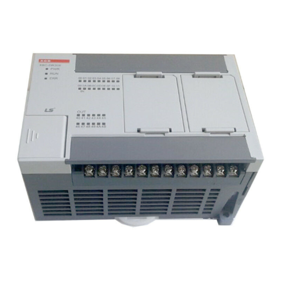
Chapter 7 Input/Output Specifications 7.2.15 XBC-DR20SU 12 point DC24V input (Source/Sink type) Model Main unit XBC-DR20SU Specification Input point 12 point Insulation method Photo coupler insulation Rated input voltage DC24V About 4 ㎃ (point 0~1: about 16 ㎃, point 2~7: about 10 ㎃) -
Page 135: Xbc-Dr30Su 18 Point Dc24V Input (Source/Sink Type)
www.behaotomasyon.com Chapter 7 Input/Output Specifications 7.2.16 XBC-DR30SU 18 point DC24V input (Source/Sink type) Model Main unit XBC-DR30SU Specification Input point 18 point Insulation method Photo coupler insulation Rated input voltage DC24V About 4 ㎃ (point 0~1: about 16 ㎃, point 2~7: about 10 ㎃) Rated input current Operation voltage range DC20.4~28.8V (within ripple rate 5%) -
Page 136: Xbc-Dr40Su 24 Point Dc24V Input (Source/Sink Type)
www.behaotomasyon.com Chapter 7 Input/Output Specifications 7.2.17 XBC-DR40SU 24 point DC24V input (Source/Sink Type) Model Main unit XBC-DR40SU Specification Input point 24 point Insulation method Photo coupler insulation Rated input voltage DC24V About 4 ㎃ (point 0~1: about 16 ㎃, point 2~7: about 10 ㎃) Rated input current Operation voltage range DC20.4~28.8V (within ripple rate 5%) -
Page 137: Xbc-Dr60Su 36 Point Dc24V Input (Source/Sink Type)
www.behaotomasyon.com Chapter 7 Input/Output Specifications 7.2.18 XBC-DR60SU 36 point DC24V input (Source/Sink Type) Model Main unit XBC-DR60SU Specification Input point 36 point Insulation method Photo coupler insulation Rated input voltage DC24V About 4 ㎃ (point 0~1: about 16 ㎃, point 2~7: about 10 ㎃) Rated input current Operation voltage range DC20.4~28.8V (within ripple rate 5%) -
Page 138: Xbc-Dn20Su 12 Point Dc24V Input (Source/Sink Type)
www.behaotomasyon.com Chapter 7 Input/Output Specifications 7.2.19 XBC-DN20SU 12 point DC24V input (Source/Sink type) Model Main unit XBC-DN20SU Specification Input point 12 point Insulation method Photo coupler insulation Rated input voltage DC24V About 4 ㎃ (Contact point 0~3: about 7 ㎃) Rated input current Operation voltage range DC20.4~28.8V (within ripple rate 5%) -
Page 139: Xbc-Dn30Su 18 Point Dc24V Input (Source/Sink Type)
www.behaotomasyon.com Chapter 7 Input/Output Specifications 7.2.20 XBC-DN30SU 18 point DC24V input (Source/Sink type) Model Main unit XBC-DN30SU Specification Input point 18 point Insulation method Photo coupler insulation Rated input voltage DC24V About 4 ㎃ (point 0~1: about 16 ㎃, point 2~7: about 10mA) Rated input current Operation voltage range DC20.4~28.8V (within ripple rate 5%) -
Page 140: Xbc-Dn40Su 24 Point Dc24V Input (Source/Sink Type)
www.behaotomasyon.com Chapter 7 Input/Output Specifications 7.2.21 XBC-DN40SU 24 point DC24V input (Source/Sink Type) Model Main unit XBC-DN40SU Specification Input point 24 point Insulation method Photo coupler insulation Rated input voltage DC24V About 4 ㎃ (point 0~1: about 16 ㎃, point 2~7: about 10 ㎃) Rated input current Operation voltage range DC20.4~28.8V (within ripple rate 5%) -
Page 141: Xbc-Dn60Su 36 Point Dc24V Input (Source/Sink Type)
www.behaotomasyon.com Chapter 7 Input/Output Specifications 7.2.22 XBC-DN60SU 36 point DC24V input (Source/Sink Type) Model Main unit XBC-DN60SU Specification Input point 36 point Insulation method Photo coupler insulation Rated input voltage DC24V About 4 ㎃ (point 0~1: about 16 ㎃, point 2~7: about 10 ㎃) Rated input current Operation voltage range DC20.4~28.8V (within ripple rate 5%) -
Page 142: Xbc-Dp20Su 12 Point Dc24V Input (Source/Sink Type)
www.behaotomasyon.com Chapter 7 Input/Output Specifications 7.2.23 XBC-DP20SU 12 point DC24V input (Source/Sink type) Model Main unit XBC-DP20SU Specification Input point 12 point Insulation method Photo coupler insulation Rated input voltage DC24V About 4 ㎃ (Contact point 0~3: about 7 ㎃) Rated input current Operation voltage range DC20.4~28.8V (within ripple rate 5%) -
Page 143: Xbc-Dp30Su 18 Point Dc24V Input (Source/Sink Type)
www.behaotomasyon.com Chapter 7 Input/Output Specifications 7.2.24 XBC-DP30SU 18 point DC24V input (Source/Sink type) Model Main unit XBC-DP30SU Specification Input point 18 point Insulation method Photo coupler insulation Rated input voltage DC24V About 4 ㎃ (point 0~1: about 16 ㎃, point 2~7: about 10mA) Rated input current Operation voltage range DC20.4~28.8V (within ripple rate 5%) -
Page 144: Xbc-Dp40Su 24 Point Dc24V Input (Source/Sink Type)
www.behaotomasyon.com Chapter 7 Input/Output Specifications 7.2.25 XBC-DP40SU 24 point DC24V input (Source/Sink Type) Model Main unit XBC-DP40SU Specification Input point 24 point Insulation method Photo coupler insulation Rated input voltage DC24V About 4 ㎃ (point 0~1: about 16 ㎃, point 2~7: about 10 ㎃) Rated input current Operation voltage range DC20.4~28.8V (within ripple rate 5%) -
Page 145: Xbc-Dp60Su 36 Point Dc24V Input (Source/Sink Type)
www.behaotomasyon.com Chapter 7 Input/Output Specifications 7.2.26 XBC-DP60SU 36 point DC24V input (Source/Sink Type) Model Main unit XBC-DP60SU Specification Input point 36 point Insulation method Photo coupler insulation Rated input voltage DC24V About 4 ㎃ (point 0~1: about 16 ㎃, point 2~7: about 10 ㎃) Rated input current Operation voltage range DC20.4~28.8V (within ripple rate 5%) -
Page 146: Main Unit Digital Output Specifications
www.behaotomasyon.com Chapter 7 Input/Output Specifications 7.3 Main Unit Digital Output Specification 7.3.1 XBC-DR10E 4 point relay output Model Main unit XBC-DR10E Specification Output point 4 point Insulation method Relay insulation Rated load DC24V 2A (resistive load) / AC220V 2A (COS = 1), 5A/COM voltage/current DC5V / 1 ㎃... -
Page 147: Xbc-Dr14E 6 Point Relay Output
www.behaotomasyon.com Chapter 7 Input/Output Specifications 7.3.2 XBC-DR14E 6 point relay output Model Main unit XBC-DR14E Specification Output point 6 point Insulation method Relay insulation Rated load DC24V 2A (resistive load) / AC220V 2A (COS = 1), 5A/COM voltage/current DC5V / 1 ㎃ Min. -
Page 148: Xbc-Dr20E 8 Point Relay Output
www.behaotomasyon.com Chapter 7 Input/Output Specifications 7.3.3 XBC-DR20E 8 point relay output Model Main unit XBC-DR20E Specification Output point 8 point Insulation method Relay insulation Rated load DC24V 2A (resistive load) / AC220V 2A (COS = 1), 5A/COM voltage/current DC5V / 1 ㎃ Min. -
Page 149: Xbc-Dr30E 12 Point Relay Output
www.behaotomasyon.com Chapter 7 Input/Output Specifications 7.3.4 XBC-DR30E 12 point relay output Model Main unit XBC-DR30E Specification Output point 12 point Insulation method Relay insulation Rated load DC24V 2A (resistive load) / AC220V 2A (COS = 1), 5A/COM voltage/current DC5V / 1 ㎃ Min. -
Page 150: Xbc-Dn10E 4 Point Transistor Output (Sink Type)
www.behaotomasyon.com Chapter 7 Input/Output Specifications 7.3.5 XBC-DN10E 4 point transistor output (Sink type) Model Main unit XBC-DN10E Specification Output point 4 point Insulation method Photo coupler insulation Rated load voltage DC 12 / 24V Operation load voltage DC 10.2 ~ 26.4V range Max. -
Page 151: Xbc-Dn14E 6 Point Transistor Output (Sink Type)
www.behaotomasyon.com Chapter 7 Input/Output Specifications 7.3.6 XBC-DN14E 6 point transistor output (Sink type) Model Main unit XBC-DN14E Specification Output point 6 point Insulation method Photo coupler insulation Rated load voltage DC 12 / 24V Operation load voltage DC 10.2 ~ 26.4V range Max. -
Page 152: Xbc-Dn20E 8 Point Transistor Output (Sink Type)
www.behaotomasyon.com Chapter 7 Input/Output Specifications 7.3.7 XBC-DN20E 8 point transistor output (Sink type) Model Main unit XBC-DN20E Specification Output point 8 point Insulation method Photo coupler insulation Rated load voltage DC 12 / 24V Operation load voltage range DC 10.2 ~ 26.4V Max. -
Page 153: Xbc-Dn30E 12 Point Transistor Output (Sink Type)
www.behaotomasyon.com Chapter 7 Input/Output Specifications 7.3.8 XBC-DN30E 12 point transistor output (Sink type) Model Main unit XBC-DN30E Specification Output point 12 point Insulation method Photo coupler insulation Rated load voltage DC 12 / 24V Operation load voltage range DC 10.2 ~ 26.4V Max. -
Page 154: Xbc-Dp10E 4 Point Transistor Output (Source Type)
www.behaotomasyon.com Chapter 7 Input/Output Specifications 7.3.9 XBC-DP10E 4 point transistor output (Source type) Model Main unit XBC-DP10E Specification Output point 4 point Insulation method Photo coupler insulation Rated load voltage DC 12 / 24V Operation load voltage DC 10.2 ~ 26.4V range Max. -
Page 155: Xbc-Dp14E 6 Point Transistor Output (Source Type)
www.behaotomasyon.com Chapter 7 Input/Output Specifications 7.3.10 XBC-DP14E 6 point transistor output (Source type) Model Main unit XBC-DP14E Specification Output point 6 point Insulation method Photo coupler insulation Rated load voltage DC 12 / 24V Operation load voltage DC 10.2 ~ 26.4V range Max. -
Page 156: Xbc-Dp20E 8 Point Transistor Output (Source Type)
www.behaotomasyon.com Chapter 7 Input/Output Specifications 7.3.11 XBC-DP20E 8 point transistor output (Source type) Model Main unit XBC-DP20E Specification Output point 8 point Insulation method Photo coupler insulation Rated load voltage DC 12 / 24V Operation load voltage range DC 10.2 ~ 26.4V Max. -
Page 157: Xbc-Dp30E 12 Point Transistor Output (Source Type)
www.behaotomasyon.com Chapter 7 Input/Output Specifications 7.3.12 XBC-DP30E 12 point transistor output (Source type) Model Main unit XBC-DP30E Specification Output point 12 point Insulation method Photo coupler insulation Rated load voltage DC 12 / 24V Operation load voltage range DC 10.2 ~ 26.4V Max. -
Page 158: Xbc-Dr20Su 8 Point Relay Output
Chapter 7 Input/Output Specifications 7.3.13 XBC-DR20SU 8 point relay output Model Main unit XBC-DR20SU Specification Output point 8 point Insulation method Relay insulation Rated load DC24V 2A (resistive load) / AC220V 2A (COS = 1), 5A/COM voltage/current DC5V / 1 ㎃... -
Page 159: Xbc-Dr30Su 12 Point Relay Output
www.behaotomasyon.com Chapter 7 Input/Output Specifications 7.3.14 XBC-DR30SU 12 point relay output Model Main unit XBC-DR30SU Specification Output point 12 point Insulation method Relay insulation Rated load DC24V 2A (resistive load) / AC220V 2A (COS = 1), 5A/COM voltage/current DC5V / 1 ㎃ Min. -
Page 160: Xbc-Dr40Su 16 Point Relay Output
www.behaotomasyon.com Chapter 7 Input/Output Specifications 7.3.15 XBC-DR40SU 16 point relay output Model Main unit Specification XBC-DR40SU Output point 16 point Insulation method Relay insulation Rated load DC24V 2A (resistive load) / AC220V 2A (COS = 1), 5A/COM voltage/current DC5V / 1 ㎃ Min. -
Page 161: Xbc-Dr60Su 24 Point Relay Output
www.behaotomasyon.com Chapter 7 Input/Output Specifications 7.3.16 XBC-DR60SU 24 point relay output Model Main unit Specification XBC-DR60SU Output point 24 point Insulation method Relay insulation Rated load DC24V 2A (resistive load) / AC220V 2A (COS = 1), 5A/COM voltage/current DC5V / 1 ㎃ Min. -
Page 162: Xbc-Dn20S(U) 8 Point Transistor Output (Sink Type)
www.behaotomasyon.com Chapter 7 Input/Output Specifications 7.3.17 XBC-DN20S(U) 8 point transistor output (Sink type) Model Main unit XBC-DN20S(U) Specification Output point 8 point Insulation method Photo coupler insulation Rated load voltage DC 12 / 24V Operation load voltage range DC 10.2 ~ 26.4V Max. -
Page 163: Xbc-Dn30S(U) 12 Point Transistor Output (Sink Type)
www.behaotomasyon.com Chapter 7 Input/Output Specifications 7.3.18 XBC-DN30S(U) 12 point transistor output (Sink type) Model Main unit XBC-DN30S(U) Specification Output point 12 point Insulation method Photo coupler insulation Rated load voltage DC 12 / 24V Operation load voltage range DC 10.2 ~ 26.4V Max. -
Page 164: Xbc-Dn40Su 16 Point Tr Output (Sink Type)
www.behaotomasyon.com Chapter 7 Input/Output Specifications 7.3.19 XBC-DN40SU 16 point TR output (Sink type) Model Main unit Specification XBC-DN40SU Output point 16 point Insulation method Photo-coupler insulation Rated load voltage DC 12 / 24V Load voltage range DC 10.2 ~ 26.4V Max. -
Page 165: Xbc-Dn60Su 24 Point Tr Output (Sink Type)
www.behaotomasyon.com Chapter 7 Input/Output Specifications 7.3.20 XBC-DN60SU 24 point TR output (Sink type) Model Main unit Specification XBC-DN60SU Output point 24 point Insulation method Photo-coupler insulation Rated load voltage DC 12 / 24V Load voltage range DC 10.2 ~ 26.4V Max. -
Page 166: Xbc-Dp20Su 8 Point Transistor Output (Source Type)
www.behaotomasyon.com Chapter 7 Input/Output Specifications 7.3.21 XBC-DP20SU 8 point transistor output (Source type) Model Main unit XBC-DP20SU Specification Output point 8 point Insulation method Photo coupler insulation Rated load voltage DC 12 / 24V Operation load voltage range DC 10.2 ~ 26.4V Max. -
Page 167: Xbc-Dp30Su 12 Point Transistor Output (Source Type)
www.behaotomasyon.com Chapter 7 Input/Output Specifications 7.3.22 XBC-DP30SU 12 point transistor output (Source type) Model Main unit XBC-DP30SU Specification Output point 12 point Insulation method Photo coupler insulation Rated load voltage DC 12 / 24V Operation load voltage range DC 10.2 ~ 26.4V Max. -
Page 168: Xbc-Dp40Su 16 Point Tr Output (Source Type)
www.behaotomasyon.com Chapter 7 Input/Output Specifications 7.3.23 XBC-DP40SU 16 point TR output (Source type) Model Main unit Specification XBC-DP40SU Output point 16 point Insulation method Photo-coupler insulation Rated load voltage DC 12 / 24V Load voltage range DC 10.2 ~ 26.4V Max. -
Page 169: Xbc-Dp60Su 24 Point Tr Output (Source Type)
www.behaotomasyon.com Chapter 7 Input/Output Specifications 7.3.24 XBC-DP60SU 24 point TR output (Source type) Model Main unit Specification XBC-DP60SU Output point 24 point Insulation method Photo-coupler insulation Rated load voltage DC 12 / 24V Load voltage range DC 10.2 ~ 26.4V Max. -
Page 170: Digital Input Module Specifications
www.behaotomasyon.com Chapter 7 Input/Output Specifications 7.4 Digital Input Module Specification 7.4.1 8 point DC24V input module (Source/Sink type) Model DC input module XBE-DC08A Specification Input point 8 point Insulation method Photo coupler insulation Rated input voltage DC24V About 4 ㎃ Rated input current Operation voltage range DC20.4~28.8V (ripple rate <... - Page 171 www.behaotomasyon.com Chapter 7 Input/Output Specifications 7.4.2 16 point DC24V input module (Sink/Source type) Model DC input module XBE-DC16A XBE-DC16B Specification Input point 16 point Insulation method Photo coupler insulation Rated input voltage DC24V DC12/24V About 4 ㎃ About 4/8 ㎃ Rated input current DC20.4~28.8V Operation voltage range...
-
Page 172: Point Dc24V Input Module (Source/Sink Type)
www.behaotomasyon.com Chapter 7 Input/Output Specifications 7.4.3 32 point DC24V input module (Source/Sink type) Model DC input module XBE-DC32A Specification Input point 32 point Insulation method Photo coupler insulation Rated input voltage DC24V About 4 ㎃ Rated input current Operation voltage range DC20.4~28.8V (ripple rate <... -
Page 173: Digital Output Module Specifications
www.behaotomasyon.com Chapter 7 Input/Output Specifications 7.5 Digital Output Module Specification 7.5.1 8 point relay output module Model Relay output module XBE-RY08A Specification Output point 8 point Insulation method Relay insulation Rated load voltage / Current DC24V 2A (Resistive load) / AC220V 2A (COS = 1), 5A/COM DC5V / 1 ㎃... -
Page 174: Point Relay Output Module (Independent Point)
www.behaotomasyon.com Chapter 7 Input/Output Specifications 7.5.2 8 point relay output module (Independent point) Model Relay output module XBE-RY08B Specification Output point 8 point Insulation method Relay insulation Rated load voltage / DC24V 2A (Resistive load) / AC220V 2A (COS = 1), 2A/COM Current DC5V / 1 ㎃... -
Page 175: Point Relay Output Module
www.behaotomasyon.com Chapter 7 Input/Output Specifications 7.5.3 16 point relay output module Model Relay output module XBE-RY16A Specification Output point 16 point Insulation method Relay insulation Rated load voltage/ current DC24V 2A (Resistive load) / AC220V 2A (COS = 1), 5A/COM DC5V / 1 ㎃... -
Page 176: Point Transistor Output Module (Sink Type)
www.behaotomasyon.com Chapter 7 Input/Output Specifications 7.5.4 8 point transistor output module (Sink type) Model Transistor output module XBE-TN08A Specification Output point 8 point Insulation method Photo coupler insulation Rated load voltage DC 12 / 24V Load voltage range DC 10.2 ~ 26.4V Max. -
Page 177: Point Transistor Output Module (Sink Type)
www.behaotomasyon.com Chapter 7 Input/Output Specifications 7.5.5 16 point transistor output module (Sink type) Model Transistor output module XBE-TN16A Specification Output point 16 point Insulation method Photo coupler insulation Rated load voltage DC 12 / 24V Load voltage range DC 10.2 ~ 26.4V Max. -
Page 178: Point Transistor Output Module (Sink Type)
www.behaotomasyon.com Chapter 7 Input/Output Specifications 7.5.6 32 point transistor output module (Sink type) Model Transistor output module XBE-TN32A Specification Output point 32 point Insulation method Photo coupler insulation Rated load voltage DC 12 / 24V Load voltage range DC 10.2 ~ 26.4V Max. -
Page 179: Point Transistor Output Module (Source Type)
www.behaotomasyon.com Chapter 7 Input/Output Specifications 7.5.7 8 point transistor output module (Source type) Model Transistor output module XBE-TP08A Specification Output point 8 point Insulation method Photo coupler insulation Rated load voltage DC 12 / 24V Load voltage range DC 10.2 ~ 26.4V Max. -
Page 180: Point Transistor Output Module (Source Type)
www.behaotomasyon.com Chapter 7 Input/Output Specifications 7.5.8 16 point transistor output module (Source type) Model Transistor output module XBE-TP16A Specification Output point 16 point Insulation method Photo coupler insulation Rated load voltage DC 12 / 24V Load voltage range DC 10.2 ~ 26.4V Max. -
Page 181: Point Transistor Output Module (Source Type)
www.behaotomasyon.com Chapter 7 Input/Output Specifications 7.5.9 32 point transistor output module (Source type) Model Transistor output module XBE-TP32A Specification Output point 32 point Insulation method Photo coupler insulation Rated load voltage DC 12 / 24V Load voltage range DC 10.2 ~ 26.4V Max. -
Page 182: Combined Digital I/O Module Input Specification
www.behaotomasyon.com Chapter 7 Input/Output Specifications 7.6 Combined Digital I/O module Input Specification 7.6.1 8 point DC24V input (Source/Sink type) Model DC input module XBE-DR16A Specification Input point 8 point Insulation method Photo coupler insulation Rated input voltage DC24V About 4 ㎃ Rated input current Operation voltage range DC20.4~28.8V (within ripple rate 5%) -
Page 183: Combined Digital I/O Module Output Specification
www.behaotomasyon.com Chapter 7 Input/Output Specifications 7.7 Combined Digital I/O module Output Specification 7.7.1 8 point relay output Model Relay output module XBE-DR16A Specification Output point 8 point Insulation method Relay insulation Rated load DC24V 2A(Resistive load) / AC220V 2A(COS = 1), 5A/COM voltage / Current DC5V / 1 ㎃... -
Page 184: Io Wiring By Using Smart Link Board
www.behaotomasyon.com Chapter 7 Input/Output Specifications 7.8 IO Wiring by Using Smart Link Board 7.8.1 Smart link board Easy wiring is available by connecting the IO connector with smart link board. The available smart link and IO cable are as follows. Smart link Connection cable No. - Page 185 www.behaotomasyon.com Chapter 7 Input/Output Specifications 2) Wiring of SLT-T40P and XGB extension modulet Wiring of XGB extension module through SLP-T40P and SLT-CT101-XBE is as follows. At this time, relationship of XGB IO signal and Smart link board terminal number is as follows. The following figure describes signal allocation when SLT-CT101-XBE is used as connection cable.
- Page 186 www.behaotomasyon.com Chapter 7 Input/Output Specifications 3) I/O wiring - XBE-DC32A (SLP-T40P) Contact No. - XBE-TN32A (SLP-T40P) Contact No. - XBE-TP32A (SLP-T40P) Contact No. 7-73 www.behaotomasyon.com...
- Page 187 www.behaotomasyon.com Chapter 7 Input/Output Specifications - XBE-TN32A (SLP-RY4A) 7-74 www.behaotomasyon.com...
-
Page 188: Chapter 8 Built-In High-Speed Counter Function
www.behaotomasyon.com Chapter 8 Built-in High-speed Counter Function XGB series have built-in function of High-speed counter in main unit. This chapter describes specifications and usage of High-speed counter’s function. 8.1 High-speed Counter Specifications It describes specifications, setting and usage of function, programming and wiring with external device of built-in main unit. - Page 189 www.behaotomasyon.com Description Classification “E” type “S(U)” type Count Enable To be set through program (count available only in enable status) Preset function To be set through terminal (contact) or program Auxiliary mode Count Latch (Program setting) Count per unit time (time setting value: 1~60,000ms) (2) Counter/Preset input specification Classification Spcification...
-
Page 190: Designation Of Parts
www.behaotomasyon.com 8.1.2 Designation of parts (1) Designation of parts (a) “E” type Names Usage Terminal 1-phase 2-phase 1-phase 2-phase Counter input terminal P000 Ch0 counter input Ch0 A-phase input A-phase input Counter input terminal P001 Ch1 counter input Ch0 B-phase input B-phase input Counter input terminal P002... - Page 191 www.behaotomasyon.com (2) Interface with external devices The internal circuit of High-speed counter is as shown below. (a) “E” type Signal On/Off Terminal Internal circuit guaranteed 1-phase 2-phase voltage Ch 0 Ch 0 20.4~28.8V 2.7 kΩ Pulse input A-phase input 6V or less Ch 1 Ch 0 20.4~28.8V...
- Page 192 www.behaotomasyon.com (b) “S(U)” type Signal On/Off Terminal Internal circuit guaranteed 1-phase 2-phase voltage Ch 0 Ch 0 20.4~28.8V P0000 2.7 kΩ Pulse input A-phase input 6V or less Ch 1 Ch 0 20.4~28.8V P0001 2.7 kΩ Pulse input B-phase input 6V or less Ch 2 Ch 2...
-
Page 193: E" Type Functions
www.behaotomasyon.com 8.1.3 “E” type Functions (1) Counter mode (a) High Speed counter module can count High Speed pulses which can not be processed by CPU module’s counter instructions (CTU, CTD, CTUD, etc.), up to binary value of 32 bits (- 2,147,483,648 ~ 2,147,483,647). - Page 194 www.behaotomasyon.com b) Increasing/decreasing count operation by B-phase input signal ● 1-phase 2-input 1-multiplication operation mode A-phase input pulse counts at rising and increasing/decreasing will be decided by B-phase. A-phase input pulse A-phase input pulse Increasing/Decreasing classification rising falling B-phase input pulse Off Increasing count B-phase input pulse On Decreasing count...
- Page 195 www.behaotomasyon.com 3) CW(Clockwise)/CCW(Counter Clockwise) operation mode A-phase input pulse counts at rising , or B-phase input pulse counts at rising. Increasing operation executed when B-phase input pulse is Low with A-phase input pulse at rising, and Decreasing operation executed when A-phase input pulse is Low with B-phase input pulse at rising.
- Page 196 www.behaotomasyon.com 2 types of count can be selected for the applicable use based on functions. (a) Linear counter 1) Linear Count range: -2,147,483,648 ~ 2,147,483,647 2) If count value reaches the maximum value while increased, Carry will occur, and if count value reaches the minimum value while decreased, Borrow will occur.
- Page 197 www.behaotomasyon.com 1) During increasing count ■ Even if count value exceeds user-defined maximum value during increasing count, Carry only occurs and count does not stop differently to Linear Count. Carry occurred Ring Count maximum value Preset value ○:Not included Present position ●:Included Ring Count minimum value...
- Page 198 www.behaotomasyon.com Carry occurred 2,147,483,647 Carry occurred Ring Count maximum value Present position Ring Count minimum value (0) ○:Not included ●:Included Present position -2,147,483,648 ※If out of the user-defined ※If within the user-defined range range 4) Operation when setting Ring Count based on present count value (during decreasing count) ■...
- Page 199 www.behaotomasyon.com (3) Compared output (a) High Speed counter module has a compared output function used to compare present count value with compared value in size to output as compared. (b) Available compared outputs are 2 for 1 channel, which can be used separately. (c) Compared output conditions are 7 associated with >, =, <...
- Page 200 www.behaotomasyon.com ▪ In order to make external output, the compared equivalent output signal (P20~P27) must be set. If Compared output contact is Off, Compared coincidence output signal (internal device) is only output. Area per channel Classification Operation Ch. 0 Ch. 1 Ch.
- Page 201 www.behaotomasyon.com (e) Detailed description for compared output 1) Mode 0 (Present value < Compared value) ■ If counted present value is less than compared value, output is sent out, and if present value increases to be equal to or greater than compared value, output is not sent out. Count value 123456 123457...
- Page 202 www.behaotomasyon.com 3) Mode 2 (Count value = Compared value) ■ If present count value is equal to compared value, output is sent out. In order to turn the output Off, Compared output Enable and Compared output signal is to be On. Count value 123456 123457...
- Page 203 www.behaotomasyon.com 5) Mode 4 (Count value > Compared value) ■ If present count value is greater than compared value, output is sent out, and if count value decreases to be less than or equal to compared value, output is not sent out. 123456 123457 123458...
- Page 204 www.behaotomasyon.com 7) Mode 6 (Count value ≤ Compared output Min. value, Count value ≥ Compared output Max. value) ■ If present count value is less than or equal to compared output Min. value and greater than or equal to compared output Max. value, output is sent out, and if count value increases/decreases to exceed compared value’s range, output is not sent out.
- Page 205 www.behaotomasyon.com (4) Carry signal (a) Carry signal occurs 1) When count range maximum value of 2,147,483,647 is reached during Linear Count. 2) When user-defined maximum value of Ring Count changed to the minimum value during Ring Count. (b) Count when Carry Signal occurs 1) Count stops if Carry occurs during Linear Count.
- Page 206 www.behaotomasyon.com 6) Revolution/Unit time While auxiliary mode enable signal is On, it counts the number of input pulses for a specified time. (a) Setting 1) Input unit time and pulse number per 1 revolution Setting value is saved at the following special K are and user can designate it directly. Device area per channel Classification Channel 0...
- Page 207 www.behaotomasyon.com (b) With the displayed number of pulses updated for a specified time and the number of pulses per revolution input, Revolution/Unit time can be counted. (c) Number of Revolution per 1 second is indicated after number of pulse per 1 revolution is set and time is set to 1 second (1000ms).
- Page 208 www.behaotomasyon.com (g) The example that number of pulse per 1 revolution set to ‘10’ and time is set to 60,000 ms is as shown below. Command 1000 Revolution per time 60000㎳ 60000㎳ 60000㎳ 60000㎳ (7) Count latch (a) When Count latch signal is On, present count value is latched. (b) Setting If present counter value is to latch, Count Latch function is set ‘Use’.
- Page 209 www.behaotomasyon.com (8) Preset function It changes the current value into preset value. There are two types of preset function, internal preset and external preset. External preset is fixed as input contact point. • Preset setting value is saved at the following special K area. Area per each channel (Double word) Type Ref.
-
Page 210: S(U)" Type Functions
www.behaotomasyon.com 8.1.4 “S(U)” type Functions (1) Counter mode (a) High Speed counter module can count High Speed pulses which can not be processed by CPU module’s counter instructions (CTU, CTD, CTUD, etc.), up to binary value of 32 bits (- 2,147,483,648 ~ 2,147,483,647). - Page 211 www.behaotomasyon.com b) Increasing/decreasing count operation by B-phase input signal ● 1-phase 2-input 1-multiplication operation mode A-phase input pulse counts at rising and increasing/decreasing will be decided by B-phase. A-phase input pulse A-phase input pulse Increasing/Decreasing classification rising falling B-phase input pulse Off Increasing count B-phase input pulse On Decreasing count...
- Page 212 www.behaotomasyon.com 3) CW(Clockwise)/CCW(Counter Clockwise) operation mode A-phase input pulse counts at rising , or B-phase input pulse counts at rising. Increasing operation executed when B-phase input pulse is Low with A-phase input pulse at rising, and Decreasing operation executed when A-phase input pulse is Low with B-phase input pulse at rising.
- Page 213 www.behaotomasyon.com (a) Linear counter ■ Linear Count range: -2,147,483,648 ~ 2,147,483,647 ■ If count value reaches the maximum value while increased, Carry will occur, and if count value reaches the minimum value while decreased, Borrow will occur. ■ If Carry occurs, count stops and increasing is not available but decreasing is available. ■...
- Page 214 www.behaotomasyon.com ▪ Range of Ring counter: user defined min. value ~ user defined max. value ▪ Counter display: in case of using ring counter, user defined max. value is not displayed. 1) During increasing count ■ Even if count value exceeds user-defined maximum value during increasing count, Carry only occurs and count does not stop differently to Linear Count.
- Page 215 www.behaotomasyon.com Carry occurred 2,147,483,647 Carry occurred Ring Count maximum value Present position Ring Count minimum value ○:Not included ●:Included Present position -2,147,483,648 ※If within the user-defined range ※If out of the user-defined range 4) Operation when setting Ring Count based on present count value (during decreasing count) ■...
- Page 216 www.behaotomasyon.com (3) Compared output (a) High Speed counter module has a compared output function used to compare present count value with compared value in size to output as compared. (b) Available compared outputs are 2 for 1 channel, which can be used separately. (c) Compared output conditions are 7 associated with >, =, <...
- Page 217 www.behaotomasyon.com ■ In order to output the compared output signal, compared output enable flag set to ‘1’ after compared output condition set. Area per channel Classification Operation Ch. 0 Ch. 1 Ch. 2 Ch. 3 Ch. 4 Ch. 5 Ch. 6 Ch.
- Page 218 www.behaotomasyon.com (e) Detail of comparator output It describes detail of comparator output (based on comparator output 0) 1) Mode 0 (Present value < Compared value) ■ If counted present value is less than the minimum value of compared output 0, output is sent out, and if present value increases to be equal to or greater than the minimum value of compared output 0, output is not sent out.
- Page 219 www.behaotomasyon.com 3) Mode 2 (Count value = Compared value) ■ If present count value is equal to the minimum set value of compared output 0, output is sent out. In order to turn the output Off, Compared output Enable signal 0 or Compared Coincidence Output Enable signal 0 is to be Off.
- Page 220 www.behaotomasyon.com 5) Mode 4 (Count value > Compared Output value) ■ If present count value is greater than the minimum set value of compared output 0, output is sent out, and if count value decreases to be less than or equal to the minimum set value of compared output 0, output is not sent out.
- Page 221 www.behaotomasyon.com 7) Mode 6 (Count value ≤ Min. set value of Compared Output 0 or Count value ≥ Max. set value of Compared Output 0) ■ If present count value is less than or equal to the minimum set value of compared 0 and greater than or equal to the maximum set value of compared 0, output is sent out, and if count value increases/decreases to exceed compared value’s range, output is not sent out.
- Page 222 www.behaotomasyon.com (4) Carry signal (a) Carry signal occurs 1) When count range maximum value of 2,147,483,647 is reached during Linear Count. 2) When user-defined maximum value of Ring Count changed to the minimum value during Ring Count. (b) Count when Carry Signal occurs 1) Count stops if Carry occurs during Linear Count.
- Page 223 www.behaotomasyon.com (6) Revolution/Unit time While the Flag about the number of revolution per unit time is On, it counts the number of input pulses for a specified time. (a) Setting 1) Set the unit time and the number of pulse per 1 revolution. Setting value is saved at the following special K area and user can designate directly.
- Page 224 www.behaotomasyon.com (b) Count function of Revolution/Unit time is used to count the number of pulses for a specified time while auxiliary mode enable signal is On. (c) With the displayed number of pulses updated for a specified time and the number of pulses per revolution input, Revolution/Unit time can be counted.
- Page 225 www.behaotomasyon.com (g) The example that number of pulse per 1 revolution set to ‘10’ and time is set to 60,000 ms is as shown below. Command 1000 Revolution per time 60000㎳ 60000㎳ 60000㎳ 60000㎳ (7) Count latch When Count latch signal is On, present count value is latched. ▪...
- Page 226 www.behaotomasyon.com (8) Preset function It changes the current value into preset value. There are two types of preset function, internal preset and external preset. External preset is fixed as input contact point. • Preset setting value is saved at the following special K area. Area per each channel (Double word) Type Ref.
-
Page 227: Installation And Wiring
www.behaotomasyon.com 8.2 Installation and Wiring 8.2.1 Precaution for wiring Pay attention to the counteractions against wiring noise especially for High-speed pulse input. (1) Surely use twisted pair shielded cable, grounded with 3 class applied. (2) Keep away from power cable or I/O line which may cause noise. (3) Stabilized power should be used for filter. -
Page 228: Internal Memory
www.behaotomasyon.com 8.3 Internal Memory 8.3.1 Special area for High-speed counter Parameter and operation command area of built-in high-speed counter use a special K device. If values set in parameter are changed, it works with the changed values. At the moment, makes sure to use WRT command to save the changed value to flash. - Page 229 www.behaotomasyon.com (1) “E” type (a) Parameter setting Description Device area per channel Remark Parameter Value Setting Ch 0 Ch 1 Ch 2 Ch 3 h0000 Linear count Counter K300 K330 K360 K390 Word mode h0001 Ring count 1 phase 1 input 1 multiplication h0000 1 phase 2 input 1 multiplication h0001...
- Page 230 www.behaotomasyon.com Description Device area per channel Remark Parameter Value Setting Ch 0 Ch 1 Ch 2 Ch 3 Ring counter Max. value -2,147,483,648 ~ 2,147,483,647 K310 K340 K370 K400 DWord setting Comp. Output Min. value -2,147,483,648 ~ 2,147,483,647 K312 K342 K372 K402 DWord...
- Page 231 www.behaotomasyon.com (b) Operation command Device area per channel Parameter Ch 0 Ch 1 Ch 2 Ch 3 Counter enabling K2600 K2700 K2800 K2900 Internal preset K2601 K2701 K2801 K2901 designation of counter External preset enabling K2602 K2702 K2802 K2902 of counter Designation of K2603 K2703...
- Page 232 www.behaotomasyon.com (2) “S(U)” type (a) Parameter setting Description Device area per channel Remark Parameter Ch 0 Ch 1 Ch 2 Ch 3 Value Setting Ch 4 Ch 5 Ch 6 Ch 7 h0000 Linear count K300 K330 K360 K390 Counter Word mode K2220...
- Page 233 www.behaotomasyon.com Description Device area per channel Remark Parameter Ch 0 Ch 1 Ch 2 Ch 3 Value Setting Ch 4 Ch 5 Ch 6 Ch 7 Ring counter K308 K338 K368 K398 min. value -2,147,483,648 ~ 2,147,483,645 DWord K2228 K2258 K2288 K2318 setting...
- Page 234 www.behaotomasyon.com Description Device area per channel Remark Parameter Ch 0 Ch 1 Ch 2 Ch 3 Value Setting Ch 4 Ch 5 Ch 6 Ch 7 HFFFF No use h0000 P0020 h0001 P0021 h0002 P0022 h0003 P0023 K321 K351 K381 K411 h0004 P0024...
- Page 235 www.behaotomasyon.com (b) Operation command Device area per channel Parameter Ch 0 Ch 1 Ch 2 Ch 3 Ch 4 Ch 5 Ch 6 Ch 7 K2600 K2700 K2800 K2900 K21800 K21900 K22000 K22100 Counter enabling Internal preset designation K2601 K2701 K2801 K2901 K21801 K21901 K22001 K22101...
-
Page 236: Error Code
www.behaotomasyon.com 8.3.2 Error code It describes errors of the built-in high-speed counter. ▪ Error occurred is saved in the following area. Device area per channel Category Remark Error code K266 K276 K286 K296 K2186 K2196 K2206 K2216 Word ▪ Error codes and descriptions Error code Description (Decimal) -
Page 237: Examples: Using High-Speed Counter
www.behaotomasyon.com 8.4 Examples: Using High-speed Counter It describes examples of using high-speed counter. (1) Setting high-speed counter parameter How to set types of parameters to operate a high-speed counter is described as follows. (a) Set 『Internal Parameters』 in the basic project window. (b) Selecting high-speed counter opens a window to set high-speed counter parameters as follows. - Page 238 www.behaotomasyon.com (c) Turn ‘ON’ the high-speed counter Enable signal (CH0:K2600) in the program. (d) To use additional functions of the high-speed counter, you needs to turn on the flag allowing an operation command. * Refer to 2) Operation Command, <8.3.1 Special K Area for High-speed Counter> For instance, turn on 2605 bit if among additional functions, rotation number function is used.
- Page 239 www.behaotomasyon.com (2) Monitoring and setting command Monitoring and command setting of high-speed counter are described as follows. (a) If starting a monitor and clicking a Special Module Monitor, the following window is opened. www.behaotomasyon.com...
- Page 240 www.behaotomasyon.com (b) Clicking 『Monitor』 shows monitor and test window of high-speed counter. Item Description FLAG Monitor Show flag monitoring and command window of high-speed counter Start Monitoring Start monitoring each item (special K device area monitor). Write each item setting to PLC. Test (Write the setting to special K device) Close...
- Page 241 www.behaotomasyon.com (c) Clicking 『Start Monitoring』shows the high-speed counter monitor display, in which you may set each parameter. At this moment, if any, changed values are not saved if power off=> on or mode is changed. (d) Clicking『FLAG Monitor』 shows the monitor of each flag in high-speed counter, in which you may direct operation commands by flags (clicking commands reverse turn).
-
Page 242: Chapter 9 Rtc Option Board
www.behaotomasyon.com Chapter 9 RTC Option Board Chapter 9 RTC Option Board 9.1 Battery 9.1.1 Battery specification Item Specification Voltage/Current DC 3V / 220 mA Warranty period 3 years (ambient temp.) Program and data backup, Purpose RTC operation in case of power failure Specification Manganese Dioxide lithium battery ... -
Page 243: How To Change Battery
www.behaotomasyon.com XGB RTC Option Board Manual 9.1.4 How to change battery The user should change the battery used to save the program and backup the data in case of power failure periodically. Though the user eliminate the battery, it works for 30 minute by super capacitor. Change the battery as fast as possible. -
Page 244: Rtc Function
www.behaotomasyon.com Chapter 9 RTC Option Board 9.2 RTC Function standard type (XBC-DxxxS, XBC-DxxxSU) doesn’t support RTC Economic type (XBC-DxxxE), function. If you equip RTC option board, you can use this function for time management of system or error log. RTC function is executed steadily when power is off or instantaneous power cut status. Current time of RTC is renewed every scan by system operation status information flag. - Page 245 www.behaotomasyon.com XGB RTC Option Board Manual (c) Modification of clock data by program area Content M0000 Month, year M0001 Hour, date M0002 Second, minute M0003 Centaury, day Write clock data to temporary device (P, M, K, L, Z, U, D, R) and turn on/off input contact point M0100.
-
Page 246: Name And Function Of Each Part
www.behaotomasyon.com Chapter 9 RTC Option Board 9.3 Name and Function of Each Part Describes the name and function of each part ① Hook for fixation ② Option board cover ③ Battery cover ④ Hook for fixation Name Contents Hook for ①④... -
Page 247: Chapter 10 Dc Input Option Function
www.behaotomasyon.com Chapter 10 DC Input Option Board Chapter 10 DC Input Option Function This chapter describes specifications and usage of input option board‟s function. 10.1 DC input Option Board Specification 10.1.1 DC Input Option Board Specification Specification of XGB input option board is as follows. DC input specification Item XBO-DC04A... -
Page 248: High Speed Counter Specification
www.behaotomasyon.com Chapter 10 DC Input Option Board 10.2 High Speed Counter Specification High speed counter function is built in XGB input option board. It describes specifications, setting and usage of function, programming and wiring with external device. 10.2.1 Performance Specification Performance Specification Specification Item... -
Page 249: Name Of Each Part
www.behaotomasyon.com Chapter 10 DC Input Option Board 10.2.2 Name of Each Part Name of each part Name XBO-DC04A Structure Name Usage Terminal 1-phase 2-phase 1-phase 2-phase A-phase input Counter input terminal Ch0 counter input Ch0 A-phase input terminal B-phase input Counter input terminal Ch1 counter input Ch0 B-phase input... - Page 250 www.behaotomasyon.com Chapter 10 DC Input Option Board (2) Interface with external devices The following table describes interface with external devices Signal Input Terminal Internal circuit guaranteed 1-phase 2-phase voltage 20.4~28.8V A-phase 2.7 k Pulse input 6V or less input 20.4~28.8V CH 1 2.7 k...
-
Page 251: Function
www.behaotomasyon.com Chapter 10 DC Input Option Board 10.2.3 Function Counter mode (a) High Speed counter module can count High Speed pulses which can not be processed by CPU module‟s counter instructions (CTU, CTD, CTUD, etc.), up to binary value of 32 bits (-2,147,483,648 ~ 2,147,483,647). - Page 252 www.behaotomasyon.com Chapter 10 DC Input Option Board b) Increasing/decreasing count operation by B-phase input signal •1-phase 2-input 1-multiplication A-phase input pulse is counted at rising and increasing/decreasing will be decided by B-phase. A-phase input pulse A-phase input pulse Increasing/Decreasing rising falling classification B-phase input pulse Off...
- Page 253 www.behaotomasyon.com Chapter 10 DC Input Option Board (2) Counter type Option board supports linear counter. (a) Linear counter 1) Linear Count range: -2,147,483,648 ~ 2,147,483,647 2) If count value reaches the maximum value while increased, Carry will occur, and if count value reaches the minimum value while decreased, Borrow will occur.
- Page 254 www.behaotomasyon.com Chapter 10 DC Input Option Board (5) Count latch (a) When Count latch signal is On, present count value is latched (b) Setting If present counter value is to latch, Count Latch function is set „Use‟. Device area per channel Type Ref.
-
Page 255: Installation And Wiring
www.behaotomasyon.com Chapter 10 DC Input Option Board 10.3 Installation and Wiring 10.3.1 Precaution for wiring Pay attention to the counteractions against wiring noise especially for High-speed pulse input Surely use twisted pair shielded cable, grounded with 3 class applied. Keep away from power cable or I/O line which may cause noise. Stabilized power should be used. - Page 256 www.behaotomasyon.com Chapter 10 DC Input Option Board In case of pulse generator is open collector type CHSC Pulse Generator Pulse generator High-speed counter input 24VG 10 - 10 www.behaotomasyon.com...
-
Page 257: Internal Memory
www.behaotomasyon.com Chapter 10 DC Input Option Board 10.4 Internal Memory 10.4.1 Special area for High-speed counter U device is used for parameter and operation command area of built-in high-speed counter. This chapter describes on how to register basic paramter and each item. U device auto-registration (a) Set the module at slot in [I/O parameter] (b) Double-click [Variable/comment]... - Page 258 www.behaotomasyon.com Chapter 10 DC Input Option Board (d) Click „Yes‟. (e) Variables are registered as follows. Note When registered by “auto-registration”, data type is expressed as BIT, WORD. If you want to check with other types such as DINT, DWORD, change the type. 10 - 12 www.behaotomasyon.com...
- Page 259 www.behaotomasyon.com Chapter 10 DC Input Option Board No. 9 slot device area (a) Action command Device area per each channel Type Ref. Enable counter U9.0.0 U9.8.0 U9.16.0 U9.24.0 Enable internal preset U9.0.1 U9.8.1 U9.16.1 U9.24.1 Count inc/dec flag U9.0.3 U9.8.3 U9.16.3 U9.24.3 Latch counter enable...
- Page 260 www.behaotomasyon.com Chapter 10 DC Input Option Board Parameter setup (a) Action command Device status information (based on slot 9, ch0) Type Ref. Information Enable counter U9.0.0 0: disable, 1: enable Enable internal preset U9.0.1 0: disable, 1: enable Count inc/dec flag U9.0.3 0: INC, 1: DEC Latch counter enable...
-
Page 261: Example Using High-Speed Counter
www.behaotomasyon.com Chapter 10 DC Input Option Board 10.5 Example using high-speed counter Describes on option board high-speed counter example High-speed counter setup Set up option board high-speed counter operation by using U area. (a) Select high-speed counter mode. Set up high-speed counter mode (b) If you need „Preset‟... -
Page 262: Chapter11 Tr Output Option Board
www.behaotomasyon.com Chapter 11 TR Output Option Board Chapter11 TR Output Option Board This chapter describes specification and how to use the output option board. 11.1 TR Output Option Board Operation Sequence of Positioning 11.1.1 Operation Sequence of Positioning Operation sequence is as follows. Positioning function of the option board operates only at slot number 9. 11 - 1 www.behaotomasyon.com... -
Page 263: Xbo-Tn04A Specification
www.behaotomasyon.com Chapter 11 TR Output Option Board 11.2 XBO-TN04A Specification 11.2.1 Output option board specification Transistor output specification Item XBO-TN04A Remark 4 (Pulse output function is supported when No. of output mounted on standard type) Insulation method Photo coupler insulation Rated load voltage DC 24V Max. -
Page 264: Positioning Specification
www.behaotomasyon.com Chapter 11 TR Output Option Board 11.3 Positioning Specification Positioning function is built in XGB output option board. This describes specification, how-to-use, function, programming and wiring of built-in positioning. 11.3.1 Performance Specification Performance Specification Model XBO-TN04A Item No. of axes Control method Position control, speed control Control unit... - Page 265 www.behaotomasyon.com Chapter 11 TR Output Option Board Connector Output point No. Description Remark Positioning X-axis pulse string output point X-axis Pulse (Open collector output) output Positioning Y-axis pulse string output point Y-axis (Open collector output) High Active Positioning X-axis direction output point X-axis Direction (Open collector output)
-
Page 266: Before Positioning
www.behaotomasyon.com Chapter 11 TR Output Option Board 11.3.3 Before Positioning Positioning function list Positioning function of XGB option board built-in positioning is as follows. Positioning description Instruction Ref. function Speed Operation Time pattern Start command Position control Dec. stop If the rising edge of start command is detected, it moves with designated Operation speed to designated position, and complete signal is on (dwell is not supported) - Page 267 www.behaotomasyon.com Chapter 11 TR Output Option Board Position control Position control is to move the designated axis from start address (present position) up to target address (movement). There are two position control methods, absolute and incremental. Control by absolute coordinates (Absolute coordinates) Object moves from start address to target address.
-
Page 268: Positioning Stop Factor
www.behaotomasyon.com Chapter 11 TR Output Option Board 11.3.4 Positioning Stop Factor (1) Stop factor and how to deal with stop factor • If following factor occurs during positioning, it stops without completing positioning. In case positioning stops by stop instruction (STP, EMG) or following stop factor, generally, the only axis where stop instruction is executed or stop factor occurs stops. -
Page 269: Manual Operation
www.behaotomasyon.com Chapter 11 TR Output Option Board (d) Emergency stop • It immediately stops if it meets emergency stop while performing start-related instructions (indirect start, direct start, Home Return start, jog start). • Emergency stop generates Error 481. • Since it turns into “Output prohibited status” and “un-defined origin status”, once emergency stop is executed, execute origin determination (Home return, Current position preset) again to run an instruction that requires defined origin status”... -
Page 270: Home Return
www.behaotomasyon.com Chapter 11 TR Output Option Board 11.3.6 Home return XBO-TN04A supports only “Home return by DOG”. (a) If homing command (ORG instruction) is executed, it accelerates to home direction set in Home Parameter and it homes with high speed. (The above figure is example when homing direction is forward) (b) While target is homing with high speed, if rising edge of DOG (U9.1.B: X-axis) occurs, target speed decreases and change its direction. -
Page 271: Positioning Basic Parameter Setup
www.behaotomasyon.com Chapter 11 TR Output Option Board 11.3.7 Positioning Basic Parameter Setup This chapter describes on how to register basic parameter of XGB main output option board positioning function and each item. (1) U device auto registration (a) Set up the module at the slot in [I/O Parameter] (b) Double-click [Variable/Comment]. - Page 272 www.behaotomasyon.com Chapter 11 TR Output Option Board (d) Click „yes‟. (e) Variables are registered as the screen below. Note When variables are registered by above method, variables are expressed by BIT and WORD. If you want to check them as DINT, DOWRD, change the data type. 11 - 11 www.behaotomasyon.com...
- Page 273 www.behaotomasyon.com Chapter 11 TR Output Option Board (2) Positioning parameter of XBO-TN04A U area of each item is as follows. U area for Signal positioning Item Data type Status information direction X-axis Y-axis BUSY 0: Stop, 1: Run U9.0.0 U9.16.0 Error 0: No error, 1: Error occurred U9.0.1...
- Page 274 www.behaotomasyon.com Chapter 11 TR Output Option Board U area for Signal positioning Item Data type Status information direction X-axis Y-axis 0: JOG low speed, JOG low/high speed U9.1.A U9.17.A 1: JOG high speed Operate at rising edge U9.1.B U9.17.B Upper limit signal Detected at falling edge U9.1.C U9.17.C...
-
Page 275: Positioning Instruction List
www.behaotomasyon.com Chapter 11 TR Output Option Board 11.4 Positioning Instruction List Positioning instructions used in XBO-TN04A positioning are summarized as follows. (1) XBO-TN04A positioning instruction XGB built-in Instructi Command Command condition positioning manual Home return Slot, command axis 5.2.1 Slot, command axis, position, speed, dwell time, M code, Direct start 5.2.3 control word... -
Page 276: Positioning Example
www.behaotomasyon.com Chapter 11 TR Output Option Board 11.5 Positioning Example This chapter describes positioning example of XBO-TN04A. Positioning setup Option board positioning is set up by U area. Set up each parameter to use positioning function. (a) Input each parameter value. X-axis bias speed Speed limit X acc. - Page 277 www.behaotomasyon.com Chapter 11 TR Output Option Board (c) Set up the function as follows. Monitoring You can check option board posioing speed, crrent position by regstering U9.2, U9.4(No. 9 slot, X-axis) at variable monitor window or program 11 - 16 www.behaotomasyon.com...
-
Page 278: Chapter12 Memory Module
www.behaotomasyon.com Chapter 12 Memory Module Chapter12 Memory Module 12.1 Memory Module Specification You can save user program safely or download user program to PLC without special handling when user program is damaged by using external memory module in XGB PLC 12.1.1 Memory module specification Item XBO-M2MB... -
Page 279: How To Use Memory Module
www.behaotomasyon.com Chapter 12 Memory Module 12.1.3 How to use memory module (1) Save program, parameter, communication parameter at external memory module (a) Set the switch of memory module as 1 (b) Install memory module at the RS-232C port of main unit - After installation, program and parameter (including communication) is saved into memory module and READ LED is on - If Saving program and parameter is complete, READ LED is off... - Page 280 www.behaotomasyon.com Chapter 12 Memory Module (e) With above method, through PADT, you can save program, parameter, communication parameter at XBO-M2MB (4) Open from memory module (a) Set the mode switch of XBO-M2MB as “5” and connect XBO-M2MB to USB port of PC (b) Select “Project ...
- Page 281 www.behaotomasyon.com Chapter 12 Memory Module (e) With above method, through PADT, you can save program, parameter, communication parameter from XBO-M2MB (5) Write to Memory module (a) Set the mode switch of XBO-M2MB as “5” and connect XBO-M2MB to USB port (b) Click “Online ...
- Page 282 www.behaotomasyon.com Chapter 12 Memory Module (d) If “Enable Link” window appears, check the item and press “Write” (e) “Enable, Disable” window appears 12-5 www.behaotomasyon.com...
- Page 283 www.behaotomasyon.com Chapter 12 Memory Module (6) Read from Memory module (a) Set the mode switch of XBO-M2MB as “5” and connect XBO-M2MB to USB port of PC (b) Select “Online Read from Memory module” on XG-PD menu. (c) If you click “OK” button”, it read each parameter form the memory module. Note -.
-
Page 284: How To Use When Password Is Set
www.behaotomasyon.com Chapter 12 Memory Module 12.1.4 How to use when password is set (1) When connecting PADT with memory module (a) When setting password at program and writing program to memory module, it is saved according to rotary switch operating mode without functions cancelling the password 1) When writing program, check whether to use password at „Write‟... - Page 285 www.behaotomasyon.com Chapter 12 Memory Module (2) Write to PLC by memory module (a) When password of program in memory module is not set 1) When no password is set in PLC - Saves program of the memory module in PLC 2) When password is set in PLC - Writing is not executed (b) When password of program in memory module is set...
- Page 286 www.behaotomasyon.com Chapter 12 Memory Module (3) Reading program in PLC to memory module (a) When password of program in PLC is not set 1) When no password is set in the memory module - Reads program from PLC 2) When password is set in the memory module - After reading, it clears password of the memory module (b) When password of program in PLC is set 1) When no password is set in the memory module...
-
Page 287: Chapter 13 Installation And Wiring
www.behaotomasyon.com Chapter 13 Installation and Wiring Chapter 13 Installation and Wiring 13.1 Safety Instruction Danger Please design protection circuit at the external of PLC for entire system to operate safely because an abnormal output or an malfunction may cause accident when any error of external power or malfunction of PLC module. - Page 288 www.behaotomasyon.com Chapter 13 Installation and Wiring Danger Don’t close the control line or communication cable to main circuit or power line. Distance should be more than 100mm. It may cause malfunction by noise. In case of controlling lamp load, heater, solenoid valve, etc. in case of Off -> On, large current (10 times of normal current) may flows, so consider changing the module to module that has margin at rated current.
-
Page 289: Fail Safe Circuit
www.behaotomasyon.com Chapter 13 Installation and Wiring 13.1.1 Fail safe circuit (1) example of system design (In case of not using ERR contact point of power module) In case of AC In case of AC . DC Power Power Check direct Trans Trans current... - Page 290 www.behaotomasyon.com Chapter 13 Installation and Wiring (2) System design circuit example (In case of using ERR contact point of power module) Power Checking Trans Trans Fuse Fuse current Signal input F0045 DC power Start stop circuit Fuse F009C Timer setting PLC RUN output which DC input Available to start as...
- Page 291 www.behaotomasyon.com Chapter 13 Installation and Wiring (3) Fail safe countermeasure in case of PLC error Error of PLC CPU and memory is detected by self diagnosis but in case error occurs in IO control part, etc., CPU can detect the error. At this case, though it is different according to status of error, all contact point is on or off, so safety may not be guaranteed.
-
Page 292: Plc Heat Calculation
www.behaotomasyon.com Chapter 13 Installation and Wiring 13.1.2 PLC heat calculation (1) Power consumption of each part (a) Power consumption of module The power conversion efficiency of power module is about 70% and the other 30% is gone with heat; 3/7 of the output power is the pure power consumption. Therefore, the calculation is as follows. ... - Page 293 www.behaotomasyon.com Chapter 13 Installation and Wiring (e) Input average power consumption of input module (power consumption of simultaneous On point) W X E X input point X simultaneous On rate (W) : input current (root mean square value in case of AC) (A) E : input voltage (actually used voltage) (V) (f) Power consumption of special module power assembly ...
-
Page 294: Attachment/Detachment Of Modules
www.behaotomasyon.com Chapter 13 Installation and Wiring 13.2 Attachment/Detachment of Modules 13.2.1 Attachment/Detachment of modules Caution in handling Use PLC in the range of general specification specified by manual. In case of using out of range, it may cause electric shock, fire, malfunction, damage of product. Warning ... - Page 295 www.behaotomasyon.com Chapter 13 Installation and Wiring (2) Detachment of module Get up the hook for fixation of upper part and lower part and disconnect it. Detach the module with two hands. (Don’t force over-applied force.) Hook for module fixation Caution ...
- Page 296 www.behaotomasyon.com Chapter 13 Installation and Wiring (3) Installation of module XGB PLC is having hook for DIN rail (rail width: 35mm) so that cab be installed at DIN rail. (a) In case of installing at DIN rail Pull hook for DIN rail at the bottom of module and install it at DIN rail ...
- Page 297 www.behaotomasyon.com Chapter 13 Installation and Wiring (4) Module equipment location Keep the following distance between module and structure or part for well ventilation and easy detachment and attachment. 30 ㎜ or above 20 ㎜ or above 30 ㎜ or above 5 ㎜...
- Page 298 www.behaotomasyon.com Chapter 13 Installation and Wiring (6) Distance with other device To avoid radiation noise or heat, keep the distance between PLC and device (connector and relay) as far as the following figure. Device installed in front of PLC: 100 ㎜ or above Device installed beside PLC: 50 ㎜...
-
Page 299: Caution In Handling
www.behaotomasyon.com Chapter 13 Installation and Wiring 13.2.2 Caution in handling Here describes caution from open to install Don’t drop or impact product. Don’t disassemble the PCB from case. It may cause the error. In case of wiring, make sure foreign substance not to enter upper part of module. -
Page 300: Wire
www.behaotomasyon.com Chapter 13 Installation and Wiring 13.3 Wire In case using system, it describes caution about wiring. Danger When wiring, cut off the external power. If all power is cut, it may cause electric shock or damage of product. In case of flowing electric or testing after wiring, equip terminal cover included in product. It not, it may cause electric shock. - Page 301 www.behaotomasyon.com Chapter 13 Installation and Wiring (3) Isolate the PLC power, I/O devices and power devices as follows. Main unit Main power Constant power Voltage AC220V Transformer AC100-240V IO power Main circuit device (4) If using DC24V of the main unit (a) Do not connect DC24V of several power modules in parallel.
- Page 302 www.behaotomasyon.com Chapter 13 Installation and Wiring (8) To prevent surge from lightning, use the lightning surge absorber as presented below. I/O device Surge absorber to prevent lighting 낙뢰 방지용 서지 업소 Note 버 (1) Isolate the grounding(E1) of lightning surge absorber from the grounding(E2) of the PLC. (2) Select a lightning surge absorber type so that the max.
-
Page 303: I/O Device Wiring
www.behaotomasyon.com Chapter 10 Installation and Wiring I/O Device wiring 13.3.2 (1) The size of I/O device cable is limited to 0.3~2 mm but it is recommended to select a size(0.3 mm ) to use conveniently. (2) Please isolate input signal line from output signal line. (3) I/O signal lines should be wired 100mm and more away from high voltage/high current main circuit cable. -
Page 304: Specifications Of Wiring Cable
www.behaotomasyon.com Chapter 10 Installation and Wiring Specifications of wiring cable 13.3.4 The specifications of cable used for wiring are as follows. Cable specification (mm Types of external connection Lower limit Upper limit Digital input 0.18 (AWG24) 1.5 (AWG16) Digital output 0.18 (AWG24) 2.0 (AWG14) Analogue I/O... -
Page 305: Chapter 14 Maintenance
www.behaotomasyon.com Chapter 14 Maintenance Chapter 14 Maintenance Be sure to perform daily and periodic maintenance and inspection in order to maintain the PLC in the best conditions. 14.1 Maintenance and Inspection The I/O module mainly consist of semiconductor devices and its service life is semi-permanent. However, periodic inspection is requested for ambient environment may cause damage to the devices. -
Page 306: Periodic Inspection
www.behaotomasyon.com Chapter 14 Maintenance 14.3 Periodic Inspection Check the following items once or twice every six months, and perform the needed corrective actions. Corrective Check Items Checking Methods Judgment Actions Ambient 0 ~ 55 C Adjust to general temperature -. Measure with thermometer standard Ambient Ambient Humidity... -
Page 307: Chapter 15 Troubleshooting
www.behaotomasyon.com Chapter 15 Troubleshooting Chapter 15 Troubleshooting The following explains contents, diagnosis and corrective actions for various errors that can occur during system operation. 15.1 Basic Procedure of Troubleshooting System reliability not only depends on reliable equipment but also on short downtimes in the event of fault. The short discovery and corrective action is needed for speedy operation of system. - Page 308 www.behaotomasyon.com Chapter 15 Troubleshooting 15.2.1 Troubleshooting flowchart used when the PWR (Power) LED turns Off. The following flowchart explains corrective action procedure used when the power is supplied or the power LED turns Off during operation. Power LED is turned Off. Is the power supply Supply the power.
-
Page 309: Troubleshooting Flowchart Used With When The Err(Error) Led Is Flickering
www.behaotomasyon.com Chapter 15 Troubleshooting 15.2.2 Troubleshooting flowchart used with when the ERR (Error) LED is flickering The following flowchart explains corrective action procedure use when the power is supplied star ts or the ERR LED is flickering during operation. STOP LED goes flickering Check the error code, with connected XG5000. -
Page 310: Troubleshooting Flowchart Used With When The Run,Stop Led Turns Off
www.behaotomasyon.com Chapter 15 Troubleshooting 15.2.3 Troubleshooting flowchart used with when the RUN , STOP LED turns Off. The following flowchart explains corrective action procedure to treat the lights-out of RUN LED when the power is supplied, operation starts or operation is in the process. RUN, STOP LED is Off. - Page 311 www.behaotomasyon.com Chapter 15 Troubleshooting 15.2.4 Troubleshooting flowchart used when the I/O part doesn’t operate normally. The following flowchart explains corrective action procedure used when the I/O module doesn’t operate normally. When the I/O module doesn’t work normally. I\s the output LED of SOL1 Replace the connector of Measure the voltage of terminal Correct wiring.
- Page 312 www.behaotomasyon.com Chapter 15 Troubleshooting Continue Are the indicator LED of the switch 1 and 2 on? Check voltage of switch 1,2 Check voltage of switch 1,2 by tester by tester Is the Is the measured value terminal screw tighten Is the measured value securely? normal? normal?
-
Page 313: Troubleshooting Questionnaire
www.behaotomasyon.com Chapter 15 Troubleshooting 15.3 Troubleshooting Questionnaire When problems have been met during operation of the XGC series, please write down this Questionnaires and contact the service center via telephone or facsimile. For errors relating to special or communication modules, use the questionnaire included in the User’s manual of the unit. -
Page 314: Troubleshooting Examples
www.behaotomasyon.com Chapter 15 Troubleshooting 15.4 Troubleshooting Examples Possible troubles with various circuits and their corrective actions are explained. 15.4.1 Input circuit troubles and corrective actions The followings describe possible troubles with input circuits, as well as corrective actions. Cause Condition Corrective Actions Leakage current of external device ... -
Page 315: Output Circuit And Corrective Actions
www.behaotomasyon.com Chapter 15 Troubleshooting 15.4.2 Output circuit and corrective actions The following describes possible troubles with output circuits, as well as their corrective actions. Condition Cause Corrective Action Load is half-wave rectified inside (in some Connect registers of tens to hundreds KΩ When the output is off, excessive cases, it is true of a solenoid) - Page 316 www.behaotomasyon.com Chapter 15 Troubleshooting Output circuit troubles and corrective actions (continued). Condition Cause Corrective actions Over current at off state [The large Insert a small L/R magnetic contact and The load off response solenoid current fluidic load (L/R is large) drive the load using the same contact.
-
Page 317: Error Code List
www.behaotomasyon.com Chapter 15 Troubleshooting 15.5 Error Code List Error Action Operation Diagnosis Error cause code (restart mode after taking an action) status status point Program to execute is 0.5 second Start after reloading the program Warning abnormal Flicker mode Start after reloading I/O parameter, Reset Battery change if battery has a problem. - Page 318 www.behaotomasyon.com Chapter 15 Troubleshooting Error Action Operation Diagnosis Error cause code (restart mode after taking an action) status status point Data memory backup If not error in battery, power reinput 1 second Warning Reset not possible Remote mode is switched to STOP mode. Flicker Setting the time by XG5000 if there is no 0.1 second...
-
Page 319: Appendix 1 Flag List
www.behaotomasyon.com Appendix 1 Flag List Appendix 1 Flag List Appendix 1.1 Special Relay (F) List (1) “S(U)” type Word Variables Function Description _SYS_STATE Mode and state Indicates PLC mode and operation State. F0000 _RUN Run state. F0001 _STOP Stop Stop state. F0002 _ERROR Error... - Page 320 www.behaotomasyon.com Appendix 1 Flag List Word Variable Function Description F0028 _BPRM_ER Basic parameter Basic parameter error. F0029 _IOPRM_ER IO parameter I/O configuration parameter error. Special module parameter is F002A _SPPRM_ER Special module parameter Abnormal. Communication module Communication module parameter F002B _CPPRM_ER F002~3 parameter...
- Page 321 www.behaotomasyon.com Appendix 1 Flag List Word Variable Function Description _USER_CLK User Clock Clock available for user setting. F0100 _USR_CLK0 Setting scan repeat On/Off as much as set scan Clock 0. F0101 _USR_CLK1 Setting scan repeat On/Off as much as set scan Clock 1. F0102 _USR_CLK2 Setting scan repeat...
- Page 322 www.behaotomasyon.com Appendix 1 Flag List Word Variable Function Description Clock data (Hundred year/week) F0056 _HUND_WK Hundred year/week Supported when using RTC option module _FPU_INFO F0570 _FPU_LFLAG_I F0571 _FPU_LFLAG_U F0572 _FPU_LFLAG_O F0573 _FPU_LFLAG_Z F0574 _FPU_LFLAG_V F057 F057A _FPU_FLAG_I F057B _FPU_FLAG_U F057C _FPU_FLAG_O F057D _FPU_FLAG_Z...
- Page 323 www.behaotomasyon.com Appendix 1 Flag List Word Variable Function Description F104 _IO_DEER0 Module Detach 0 error Main base module Detach error. F120 _IO_RWER0 Module RW 0 error Main base module read/write error. F128 _IO_IFER_0 Module IF 0 error Main base module interface error. F140 _AC_FAIL_CNT Power shutdown times...
- Page 324 www.behaotomasyon.com Appendix 1 Flag List (2) “E” type Word Variables Function Description _SYS_STATE Mode and state Indicates PLC mode and operation State. F0000 _RUN Run state. F0001 _STOP Stop Stop state. F0002 _ERROR Error Error state. F0003 _DEBUG F0004 _LOCAL_CON Local control Local control mode.
- Page 325 www.behaotomasyon.com Appendix 1 Flag List Word Variable Function Description F0028 _BPRM_ER Basic parameter Basic parameter error. F0029 _IOPRM_ER IO parameter I/O configuration parameter error. Special module parameter is F002A _SPPRM_ER Special module parameter Abnormal. Communication module Communication module parameter F002B _CPPRM_ER F002~3 parameter...
- Page 326 www.behaotomasyon.com Appendix 1 Flag List Word Variable Function Description _USER_CLK User Clock Clock available for user setting. F0100 _USR_CLK0 Setting scan repeat On/Off as much as set scan Clock 0. F0101 _USR_CLK1 Setting scan repeat On/Off as much as set scan Clock 1. F0102 _USR_CLK2 Setting scan repeat...
- Page 327 www.behaotomasyon.com Appendix 1 Flag List Word Variable Function Description Clock data (Hundred year/week) F0056 _HUND_WK Hundred year/week Supported when using RTC option module _FPU_INFO F0570 _FPU_LFLAG_I F0571 _FPU_LFLAG_U F0572 _FPU_LFLAG_O F0573 _FPU_LFLAG_Z F0574 _FPU_LFLAG_V F057 F057A _FPU_FLAG_I F057B _FPU_FLAG_U F057C _FPU_FLAG_O F057D _FPU_FLAG_Z...
- Page 328 www.behaotomasyon.com Appendix 1 Flag List Word Variable Function Description F104 _IO_DEER0 Module Detach 0 error Main base module Detach error. F120 _IO_RWER0 Module RW 0 error Main base module read/write error. F128 _IO_IFER_0 Module IF 0 error Main base module interface error. F140 _AC_FAIL_CNT F142...
-
Page 329: Appendix 1.2 Communication Relay (L) List
www.behaotomasyon.com Appendix 1 Flag List Appendix 1.2 Communication Relay (L) List Here describes data link communication relay(L). (Supported in “S(U)” type) (1) High-speed Link 1 Device Keyword Type Description High speed link parameter 1 normal operation of all station Indicates normal operation of all station according to parameter set in High speed link, and On under the condition as below. - Page 330 www.behaotomasyon.com Appendix 1 Flag List (2) High-speed Link2 Device Keyword Type Description High-speed link parameter 2 normal operation of all station. Indicates normal operation of all station according to parameter set in High-speed link and On under the condition as below. L0260 _HS2_RLINK 1.
- Page 331 www.behaotomasyon.com Appendix 1 Flag List (3) Common area Communication flag list according to P2P service setting. P2P parameter: “S” type 1~3, “E” type 1 P2P block: “S” type and “E” type 0~31 Device Keyword Type Description Indicates P2P parameter 1, 0 Block service L5120 _P2P1_NDR00 normal end.
-
Page 332: Appendix 2 Dimension
www.behaotomasyon.com Appendix 2 Dimension Appendix 2 Dimension (Unit: mm) (1) Economy type main unit (“E” type) -. XBC-DR10/14E, XBC-DN10/14E, XBC-DP10/14E -. XBC-DR20/30E, XBC-DN20/30E, XBC-DP20/30E App.2 1 www.behaotomasyon.com... - Page 333 www.behaotomasyon.com Appendix 2 Dimension (2) Standard type main unit (“S(U)” type) -. XBC-DN20/30S(U), XBC-DR20/30SU, XBC-DP20/30SU - XBC-DN40SU, XBC-DR40SU¸ XBC-DP40SU App.2 2 www.behaotomasyon.com...
- Page 334 www.behaotomasyon.com Appendix 2 Dimension - XBC-DN60SU, XBC-DR60SU, XBC-DP60SU App.2 3 www.behaotomasyon.com...
- Page 335 www.behaotomasyon.com Appendix 2 Dimension (3) Extension I/O module -. XBE-DC32A, XBE-TR32A -. XBE-RY16A App.2 4 www.behaotomasyon.com...
- Page 336 www.behaotomasyon.com Appendix 2 Dimension -. XBE-DC08A, XBE-DC16A, XBE-TN08A, XBE-TN16A -. XBE-DR16A, XBE-RY08A App.2 5 www.behaotomasyon.com...
-
Page 337: Appendix 3 Compatibility With Master-K
www.behaotomasyon.com Appendix 3 Compatibility with MASTER-K (Special Relay) Appendix 3 Compatibility with MASTER-K (Special Relay) MASTER-K Symbol Device Function Device Function F0000 _RUN F0000 RUN Edit mode RUN mode F0001 F0001 Program mode Program mode _STOP F0002 F0002 Error mode Pause mode _ERROR F0003... - Page 338 www.behaotomasyon.com Appendix 3 Compatibility with MASTER-K (Special Relay) MASTER-K Symbol Device Function Device Function F0020 1 Step RUN _CPU_ER F0020 CPU configuration error F0021 Break Point RUN _IO_TYER F0021 Module type mismatch error F0022 Scan RUN _IO_DEER F0022 Module detach error F0023 Contact value match RUN _FUSE_ER...
- Page 339 www.behaotomasyon.com Appendix 3 Compatibility with MASTER-K (Special Relay) MASTER-K Symbol Device Function Device Function _LOG_FULL F0047 Log memory full warning _HS_WAR1 F0048 High speed link parameter 1 error _HS_WAR2 F0049 High speed link parameter 2 error F004A ~ F0053 _P2P_WAR1 F0054 P2P parameter 1 error F0040 ~ F005F...
- Page 340 www.behaotomasyon.com Appendix 3 Compatibility with MASTER-K (Special Relay) MASTER-K Symbol Device Function Device Function F0108 ~ F010F F0108 ~ F010F F0110 Operation error flag _Ler F0110 Operation error flag F0111 Zero flag _Zero F0111 Zero flag F0112 Carry flag _Carry F0112 Carry flag F0113...
- Page 341 www.behaotomasyon.com Appendix 3 Compatibility with MASTER-K (Special Relay) MASTER-K Symbol Device Function Device Function F0500~ F050F Max. Scan time _SCAN_MAX F0500~ F050F Max. Scan time F0510~ F051F Min. Scan time _SCAN_MIN F0510~ F051F Min. Scan time F0520~ F052F Current Scan time _SCAN_CUR F0520~ F052F Current Scan time...
- Page 342 www.behaotomasyon.com Appendix 3 Compatibility with MASTER-K (Special Relay) Note 1. When you convert the project written by KGLWIN in MASTER-K series (K80S, K200S, K300S, and K1000S) into XG5000 project, some instructions used in only MASTER-K is not converted. And the previous parameter used in MASTER-K is converted into default value.
-
Page 343: Appendix 4 Instruction List
www.behaotomasyon.com Appendix 4 Instruction List Appendix 4 Instruction List Appendix 4.1 Classification of Instructions Classification Instructions Details Remarks Contact Point Instruction LOAD, AND, OR related Instructions Unite Instruction AND LOAD, OR LOAD, MPUSH, MLOAD, MPOP Reverse Instruction Master Control Instruction MCS, MCSCLR OUT, SET, RST, 1 Scan Output Instruction, Output Reverse Output Instruction... -
Page 344: Appendix 4.2 Basic Instructions
www.behaotomasyon.com Appendix 4 Instruction List Appendix 4.2 Basic Instructions (1) Contact point instruction Support Classification Designations Symbol Description ○ ○ LOAD A Contact Point Operation Start ○ ○ LOAD NOT B Contact Point Operation Start A Contact Point Series- ○ ○... - Page 345 www.behaotomasyon.com Appendix 4 Instruction List (3) Reverse instruction Support Classification Designations Symbol Description Previous Operation results ○ ○ Reverse Reverse (4) Master Control instruction Support Classification Designations Symbol Description ○ ○ Master Control Setting (n:0~7) Master Control ○ ○ MCSCLR Master Control Cancel (n:0~7) MCSCLR (5) Output instruction...
- Page 346 www.behaotomasyon.com Appendix 4 Instruction List (9) Timer instruction Support Classification Designations Symbol Description Input ○ ○ Input ○ ○ TOFF TOFF t1+t2 = t Input ○ ○ Timer Input ○ ○ TMON TMON Input ○ ○ TRTG TRTG (10) Counter instruction...
-
Page 347: Appendix 4.3 Application Instruction
www.behaotomasyon.com Appendix 4 Instruction List Appendix 4.3 Application Instruction (1) Data transfer instruction Support Classification Designations Symbol Description 16 bits ○ ○ Transfer MOVP MOVP DMOV DMOV 32 bits ○ ○ (S+1,S) (D+1,D ) Transfer DMOVP DMOVP RMOV RMOV Short ○... - Page 348 www.behaotomasyon.com Appendix 4 Instruction List (1) Data Transfer Instruction (continued) Support Classification Designations Symbol Description ○ ○ $MOV $MOV String started from (S) String Transfer String started from (D) ○ ○ $MOVP $MOVP (2) BCD/BIN conversion instruction Support Classification Designations Symbol Description To BCD...
- Page 349 www.behaotomasyon.com Appendix 4 Instruction List (3) Data type conversion instruction Support Classification Designations Symbol Description To Real (D+1,D) ○ ○ I2RP I2RP 16 Bits Int( -32768~32767 ) Integer/Real To Long Conversion (D+3,D+2,D+1,D) ○ ○ Int( -32768~32767 ) I2LP I2LP To Real (S+1,S) (D+1,D) ○...
- Page 350 www.behaotomasyon.com Appendix 4 Instruction List (4) Comparison instruction Support Classification Designations Symbol Description CMP(S1,S2) and applicable Flag SET ○ ○ Unsigned (S1, S2 is Word) Compare CMPP CMPP with Special DCMP DCMP Relay CMP(S1,S2) and applicable Flag SET ○ ○ used (S1, S2 is Double Word) DCMPP...
- Page 351 www.behaotomasyon.com Appendix 4 Instruction List 4) Comparison instruction (continued) Support Classification Designations Symbol Description ○ ○ GDEQ GDEQ ○ ○ GDEQP GDEQP ○ ○ GDGT GDGT ○ ○ GDGTP GDGTP ○ ○ GDLT GDLT Compares S1 data to S2 data 2 by ○...
- Page 352 www.behaotomasyon.com Appendix 4 Instruction List (4) Comparison instruction (continued) Support Classification Designations Symbol Description LOAD= LOAD> > 16 Bits Compares (S1) to (S2), and saves LOAD< < Data its result in Bit Result(BR) (Signed ○ ○ Compare Operation) LOAD>= >= (LOAD) LOAD<= <=...
- Page 353 www.behaotomasyon.com Appendix 4 Instruction List (4) Comparison instruction (continued) Support Classification Designations Symbol Description ANDD= ANDD> D> 32 Bits Performs AND operation of (S1) & ANDD< D< Data (S2) Compare Result and Bit Result ○ ○ Compare (BR), and then saves its result in D>= ANDD>= (AND)
- Page 354 www.behaotomasyon.com Appendix 4 Instruction List (4) Comparison instruction (continued) Support Classification Designations Symbol Description ORR= ORR> R> ORR< Compares (S1+1,S1) to (S2+1,S2) R< Real Number and saves its result in Bit Result ○ ○ Compare (BR) (Signed Operation) (OR) ORR>= R>...
- Page 355 www.behaotomasyon.com Appendix 4 Instruction List (4) Comparison instruction (continued) Support Classification Designations Symbol Description ORL= ORL> L> Performs OR operation of (S1 Double Real ORL< +1,S1) & (S2+1,S2) Compare L< Number Result and Bit Result(BR), and ○ ○ Compare then saves its result in BR (OR) ORL>= (Signed Operation)
- Page 356 www.behaotomasyon.com Appendix 4 Instruction List (4) Comparison instruction (continued) Support Classification Designations Symbol Description OR$= OR$> $> Performs OR operation of (S1) OR$< $< String & (S2) Starting String Compare ○ ○ Compare Result and Bit Result(BR), and (OR) then saves its result in BR OR$>= $>...
- Page 357 www.behaotomasyon.com Appendix 4 Instruction List (4) Comparison instruction (continued) Support Classification Designations Symbol Description LOADDG= LOADDG> DG> Compares (S1), (S1+1), …, 32 Bits (S1+N) to (S2), (S2+1), … , DG< LOADDG< Data (S2+N) 1 to 1, and then saves ○ ○...
- Page 358 www.behaotomasyon.com Appendix 4 Instruction List (4) Comparison instruction (continued) Support Classification Designations Symbol Description LOAD3= LOAD3> 3> LOAD3< 3< Three 16-Bit Saves 1 in Bit Result(BR) if each ○ ○ Data Compare value of (S1), (S2), (S3) meets (LOAD) given condition LOAD3>= 3>= LOAD3<=...
- Page 359 www.behaotomasyon.com Appendix 4 Instruction List (4) Comparison instruction (continued) Support Classification Designations Symbol Description ANDD3= ANDD3> D3> Performs AND operation of (S1+ ANDD3< D3< Three 32-Bit 1,S1), (S2+1,S2), (S3+1,S3) Compare ○ ○ Result by given condition and Bit Data Compare Result (BR), and then saves its (AND) ANDD3>=...
- Page 360 www.behaotomasyon.com Appendix 4 Instruction List (5) Increase/Decrease instruction Support Classification Designations Symbol Description (D)+1 INCP INCP 4-94 DINC DINC (D+1,D)+1 (D+1,D) BIN Data DINCP DINCP Increase Decrease (D)-1 (Signed) DECP DECP 4-96 DDEC DDEC (D+1,D)-1 (D+1,D) DDECP DDECP INC4 INC4 (D:x bit ~ D:x bit+4) + 1 (D:x bit ~ D:x bit+4) INC4P...
- Page 361 www.behaotomasyon.com Appendix 4 Instruction List (6) Rotation instruction Support Classification Designations Symbol Description ROLP ROLP ○ ○ Rotate to Left DROL DROL DROLP DROLP ROL4 ROL4 ROL4P ROL4P 4/8 Bits ○ ○ Rotate to Left ROL8 ROL8 ROL8P ROL8P RORP RORP ○...
- Page 362 www.behaotomasyon.com Appendix 4 Instruction List (7) Move instruction Support Classification Designations Symbol Description BSFT BSFT ○ ○ Bits Move BSFTP BSFTP BSFL BSFL BSFLP BSFLP Move to Higher ○ ○ DBSFL DBSFL … … (D+1, D) DBSFLP DBSFLP BSFL4 BSFL4 BSFL4P BSFL4P Move to Higher...
- Page 363 www.behaotomasyon.com Appendix 4 Instruction List (8) Exchange instruction Support Classification Designations Symbol Description XCHG XCHG (D1) (D2) XCHGP XCHGP Data ○ ○ Exchange DXCHG DX CHG (D1+1, D1) (D2+1, D2) DXCHGP DX CHGP GXCHG GXCHG (D1) (D2) Group ○ ○ Data Exchange GXCHGP...
- Page 364 www.behaotomasyon.com Appendix 4 Instruction List (9) BIN operation instruction Support Classification Designations Symbol Description (S1)+(S2) ADDP ADDP Integer Addition ○ ○ (Signed) DADD DADD (S1+1,S1)+(S2+1,S2) (D+1,D) DADDP DADDP (S1)-(S2) SUBP SUBP Integer ○ ○ Subtraction (Signed) DSUB DSUB (S1+1,S1)-(S2+1,S2) (D+1,D) DSUBP DSUBP (S1)×(S2)
- Page 365 www.behaotomasyon.com Appendix 4 Instruction List (9) BIN operation instruction (continued) Support Classification Designations Symbol Description DIVU DIVU (D) Quotient (S1)÷(S2) (D+1) Remainder DIVUP DIVUP Integer Division ○ ○ (Unsigned) (S1+1,S1)÷(S2+1,S2) DDIVU DDIVU (D+1,D) Quotient DDIVUP DDIVUP (D+3,D+2) Remainder (S1+1,S1)+(S2+1,S2) RADD RADD (D+1,D) RADDP...
- Page 366 www.behaotomasyon.com Appendix 4 Instruction List (10) BCD operation instruction Support Classification Designations Symbol Description ADDB ADDB (S1)+(S2) ADDBP ADDBP ○ ○ BCD Addition DADDB DADDB (S1+1,S1)+(S2+1,S2) (D+1,D) DADDBP DADDBP SUBB SUBB (S1)-(S2) SUBBP SUBBP ○ ○ BCD Subtraction DSUBB DSUBB (S1+1,S1)-(S2+1,S2) (D+1,D) DSUBBP...
- Page 367 www.behaotomasyon.com Appendix 4 Instruction List (11) Logic operation instruction Basic Classification Designations Symbol Description Page Steps WAND WAND Word AND ∧ (S1) (S2) WANDP WANDP Logic ○ ○ Multiplication DWAND DWAND DWord AND ∧ (S1+1,S1) (S2+1,S2) (D+1,D) DWANDP DWANDP Word OR ∨...
- Page 368 www.behaotomasyon.com Appendix 4 Instruction List (12) Data process instruction Support Classification Designations Symbol Description BSUM BSUM 1’s number BSUMP BSUMP ○ ○ Bit Check DBSUM DBSUM 1’s number DBSUMP DBSUMP number BRST BRST ○ ○ Bit Reset Resets N Bits (starting from D) to 0 BRSTP BRSTP ENCO...
- Page 369 www.behaotomasyon.com Appendix 4 Instruction List (12) Data process instruction (continued) Support Designatio Classification Symbol Description Saves the min value in D among N words starting from S MINP MINP Min. Value ○ ○ Search DMIN DMIN Saves the min value in D among N double words starting from S DMINP DMINP...
- Page 370 www.behaotomasyon.com Appendix 4 Instruction List (13) Data table process instruction Support Classification Designations Symbol Description FIWR FIWR Adds S to the last of Data Table D ~ Data ○ ○ D+N, and increases Data Table Write Length(N) saved in D by 1 FIWRP FIWRP FIFRD...
- Page 371 www.behaotomasyon.com Appendix 4 Instruction List (15) String Process instruction Support Classification Designations Symbol Description BINDA BINDA Converts S of 1-word BIN value to Decimal ASCII Cord to save in Convert to starting D BINDAP BINDAP Decimal ○ ○ ASCII DBINDA DBINDA Converts S of 2-word BIN value to Cord...
- Page 372 www.behaotomasyon.com Appendix 4 Instruction List (15) String process instruction (continued) Support Classification Designations Symbol Description Adjusts S2 saved word data to S1 saved place number to convert to String STRP STRP and save in D Convert BIN16/32 to ○ ○ String Adjusts S2 saved double DSTR...
- Page 373 www.behaotomasyon.com Appendix 4 Instruction List (15) String process instruction (continued) Basic Classification Designations Symbol Description Page Steps REPLACE REPLACE Processes String String Random ○ ○ applicable to S2 Condition to Replace save in D String REPLACEP REPLACEP FIND FIND Finds identical String to S2 in ○...
- Page 374 www.behaotomasyon.com Appendix 4 Instruction List (16) Special function instruction Basic Classification Designations Symbol Description Page Steps SIN(S+1,S) (D+1,D) ○ ○ SIN Operation SINP SINP COS(S+1,S) (D+1,D) ○ ○ Operation COSP COSP TAN(S+1,S) (D+1,D) ○ ○ TAN Operation TANP TANP (S+1,S) (D+1,D) Converts angle to radian ○...
- Page 375 www.behaotomasyon.com Appendix 4 Instruction List (17) Data control instruction Basic Classification Designations Symbol Description Page Steps LIMIT LIMIT If S1 < S2, then D = S2 LIMITP LIMITP Limit If S2 < S1 < S3, then ○ ○ D = S1 Control DLIMIT DLIMIT...
- Page 376 www.behaotomasyon.com Appendix 4 Instruction List (18) Time related instruction Support Classification Designations Symbol Description DATERD DATERD Date/Time Reads PLC Time to save in D ~ D+6 ○ Data (Yr/Mn/Dt/Hr/Mn/Sd/Day) Read DATERDP DATERDP D DATEWR DATEWR S Date/Time Input ○ Data S ~ S+6’s Time Data in PLC (Yr/Mn/Dt/Hr/Mn/Sd/Day) Write...
- Page 377 www.behaotomasyon.com Appendix 4 Instruction List (20) Loop instruction Support Classification Designations Symbol Description Operates FOR~NEXT section n ○ ○ times Loop NEXT NEXT Instruction ○ ○ BREAK BREAK Escapes from FOR~NEXT section (21) Flag instruction Support Classification Designations Symbol Description Carry Flag ( F0112 ) SET Carry ○...
- Page 378 www.behaotomasyon.com Appendix 4 Instruction List (24) Sign reversion instruction Support Classification Designations Symbol Description Saves D value again in D with 2’s complement taken NEGP NEGP 2’s ○ ○ complement DNEG DNEG Saves (D+1,D) value again (D+1,D) with 2’s complement taken DNEGP DNEGP...
-
Page 379: Appendix 4.4 Special/Communication Instruction
www.behaotomasyon.com Appendix 4 Instruction List Appendix 4.4 Special/Communication Instruction (1) Communication module related instruction Support Classification Designations Symbol Description Sets opposite station No. for P2P ○ Station No. Set P2PSN P2PSN Communication. n1:P2P No., n2:Block, n3:Station No. Sets word data Read Area Read Area Set n1:P2P No., n2:Block, n3:Variable ○... - Page 380 www.behaotomasyon.com Appendix 4 Instruction List (3) Exclusive positioning instruction Support Classification Designations Symbol Description Instructions Positioning Module’s ax Return to Origin ○ ○ axis installed on sl slot to return to Point Origin Point Instructions Positioning Module’s ax Floating Origin ○...
- Page 381 www.behaotomasyon.com Appendix 4 Instruction List (4) Exclusive position control instruction (continued) Support Classification Designations Symbol Description Instructions Positioning Module’s ax axis Speed ○ ○ installed on sl slot to override Speed to Override change the target speed to n Instructions Positioning Module’s ax axis Position specified installed on sl slot to override position ○...
- Page 382 www.behaotomasyon.com Appendix 4 Instruction List (5) Exclusive position control instruction (continued) Support Classification Designations Symbol Description Resets Error originated from Positioning ○ ○ Error Reset Module’s ax axis installed on sl slot Deletes Error History originated from Error ○ History ECLR ECLR Positioning Module’s ax axis installed on...
- Page 383 3. Since the above warranty is limited to PLC unit only, make sure to use the product considering the safety for system configuration or applications. Environmental Policy LSIS Co.,Ltd. supports and observes the environmental policy as below. Environmental Management About Disposal LSIS’...
- Page 384 2 Zhongshan Liu Road.Guangzhou.P.R China Tel : 86-20-8328-6754/Fax : 86-20-8326-6287 e-mail : chenxs@lsis.com.cn ※ LSIS constantly endeavors to improve its product so that 2010. 3 information in this manual is subject to change without notice. ⓒ LSIS Co., Ltd. 2010 All Rights Reserved.
Need help?
Do you have a question about the XBC-DR20SU and is the answer not in the manual?
Questions and answers