LSIS XGT Series User Manual
Pnet i/f module
Hide thumbs
Also See for XGT Series:
- User manual (909 pages) ,
- Manual (48 pages) ,
- User manual (429 pages)
Table of Contents
Advertisement
Quick Links
Right choice for ultimate yield
LSIS strives to maximize customers' profit in gratitude of choosing us for your partner.
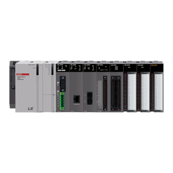
Programmable Logic Controller
XGT Series
Read this manual carefully before
installing, wiring, operating, servicing
or inspecting this equipment.
Keep this manual within easy reach
for quick reference.
Pnet I/F Module
http://www.lsis.com
User's Manual
XGL-PMEA
XGL-PMEB
XGL-PMEC
Advertisement
Table of Contents
Troubleshooting

Related Manuals for LSIS XGT Series


Summary of Contents for LSIS XGT Series
- Page 1 Right choice for ultimate yield LSIS strives to maximize customers' profit in gratitude of choosing us for your partner. Programmable Logic Controller Pnet I/F Module XGT Series User’s Manual XGL-PMEA XGL-PMEB XGL-PMEC Read this manual carefully before installing, wiring, operating, servicing or inspecting this equipment.
- Page 2 Safety Instructions Before using the product … For your safety and effective operation, please read the safety instructions thoroughly before using the product. Safety Instructions should always be observed in order to prevent accident or risk with the safe and proper use the product.
- Page 3 Safety Instructions Safety Instructions for design process Warning Please install a protection circuit on the exterior of PLC so that the whole system may operate safely regardless of failures from external power or PLC. Any abnormal output or operation from PLC may cause serious problems to safety in whole system.
- Page 4 Safety Instructions Safety Instructions for design process Caution I/O signal or communication line shall be wired at least 100mm away from a high-voltage cable or power line. Fail to follow this instruction may cause malfunctions from noise Safety Instructions on installation process Caution Use PLC only in the environment specified in PLC manual or general standard of data sheet.
- Page 5 Safety Instructions Safety Instructions for wiring process Warning Prior to wiring works, make sure that every power is turned off. If not, electric shock or damage on the product may be caused. 2. After wiring process is done, make sure that terminal covers are installed properly before its use.
- Page 6 Safety Instructions Safety Instructions for test-operation and maintenance Warning Don’t touch the terminal when powered. Electric shock or abnormal operation may occur. Prior to cleaning or tightening the terminal screws, let all the external power off including PLC power. If not, electric shock or abnormal operation may occur.
- Page 7 Safety Instructions Safety Instructions for waste disposal Caution Product or battery waste shall be processed as industrial waste. The waste may discharge toxic materials or explode itself.
- Page 8 - PROFIBUS DPv1 setting V2.4 ’16.03 - P2P communication setting - XG5000 UI updated (XGL-PMEB contents, P2P settings) ※ The num ber of User’ s m anual is indicated right part of the back cover. ⓒ LSIS Co., Ltd 2006 All Rights Reserved.
- Page 9 User’s Manual. The User’s Manual describes the product. If necessary, you may refer to the following description and order accordingly. In addition, you may connect our website (http://www.lsis.com/) and download the information as a PDF file. Relevant User’s Manuals...
-
Page 10: Table Of Contents
◎ Table of Contents ◎ Chapter 1 Introduction 1.1 Introduction -------------------------------------------------------------------------------------------------------- 1-1 1.2 Characteristics ---------------------------------------------------------------------------------------------------- 1-1 1.3 Product Configuration ------------------------------------------------------------------------------------------- 1-2 1.3.1 Model Name ------------------------------------------------------------------------------------------------ 1-2 1.3.2 Available number by CPU ------------------------------------------------------------------------------- 1-2 1.3.3 Slave Device ----------------------------------------------------------------------------------------------- 1-3 1.4 Software ------------------------------------------------------------------------------------------------------------- 1-4 1.4.1 Check list for the software ------------------------------------------------------------------------------ 1-4 1.4.2 XG5000 ------------------------------------------------------------------------------------------------------ 1-5 1.4.3 Checking the version ------------------------------------------------------------------------------------- 1-5... - Page 11 Chapter 4 System Configuration 4.1 System Configuration of Network ---------------------------------------------------------------------------- 4-1 4.1.1 XGT Pnet + Smart I/O -------------------------------------------------------------------------------- 4-1 4.1.2 XGT Pnet + Composite System -------------------------------------------------------------------- 4-2 Chapter 5 Communication Program 5.1 Communication Program --------------------------------------------------------------------------------------- 5-1 5.1.1 Type of communication program ------------------------------------------------------------------- 5-1 5.2 XG5000 ------------------------------------------------------------------------------------------------------------- 5-2 5.2.1 Setting PLC type ----------------------------------------------------------------------------------------- 5-2 5.2.2 Registration of the communication module ------------------------------------------------------- 5-4...
- Page 12 Chapter 7 N Configurator Setting 7.1 Introduction -------------------------------------------------------------------------------------------------------- 7-1 7.1.1 Main functions ------------------------------------------------------------------------------------------ 7-1 7.1.2 Characteristics ------------------------------------------------------------------------------------------ 7-1 7.2 Installation --------------------------------------------------------------------------------------------------------- 7-2 7.2.1 System requirements --------------------------------------------------------------------------------- 7-2 7.2.2 How to install Program --------------------------------------------------------------------------------- 7-2 7.3 Start PROFICON -------------------------------------------------------------------------------------------------- 7-3 7.3.1 Screen composition ------------------------------------------------------------------------------------- 7-3 7.3.2 Menu composition --------------------------------------------------------------------------------------- 7-4 7.3.3 New Project(New File) -------------------------------------------------------------------------------- 7-10 7.4 Network composition through PROFICON ----------------------------------------------------------------- 7-11...
- Page 13 12.1 Requirements Complying with EMC Specifications ---------------------------------------------------- 12-1 12.1.1 EMC specifications ----------------------------------------------------------------------------------- 12-1 12.1.2 Panel ----------------------------------------------------------------------------------------------------- 12-2 12.1.3 Cable ----------------------------------------------------------------------------------------------------- 12-3 12.2 Requirements Complying with Low Voltage Direction ------------------------------------------------ 12-4 12.2.1 Specifications applicable to XGT series --------------------------------------------------------- 12-4 12.2.2 Selection of XGT series PLC ----------------------------------------------------------------------- 12-4...
- Page 14 Appendix A.1 Terminology ------------------------------------------------------------------------------------------------------- A-1 A.2 List of Flags ------------------------------------------------------------------------------------------------------- A-3 A.2.1 High-speed link flags ------------------------------------------------------------------------------------ A-3 A.2.2 Link devices (N) ------------------------------------------------------------------------------------------ A-6 A.3 Dimensions -------------------------------------------------------------------------------------------------------- A-8...
-
Page 15: Chapter 1 Introduction
Chapter 1 Introduction Chapter 1 Introduction 1.1 Introduction This user’s manual is to describe Profibus-DP (Decentralized Peripherals) Master I/F module (hereinafter referred to as Pnet I/F module) among communication modules of XGT PLC system. Profibus-DP is specified in IEC Fieldbus Standard IEC 1158. In this communication, Token Ring is used to control the communication and to configure the network easily. -
Page 16: Product Configuration
Chapter 1 Introduction 1.3 Product Configuration 1.3.1 Model Name This describes on the product configuration of the XGT Pnet I/F module. Model Contents Remark XGL-PMEA Profibus-DP Master Supports DP-V0 XGL-PMEC Profibus-DP Master XGK/XGI/XGR XGL-PMEB Profibus-DP Master Supports DP-V1 Note (1) XGT Pnet supports only Profibus-DP. FMS, PA are not supported and protocol conversion is available by the coupler (2) Support of the DP version 1) DP-V0: Periodical data exchange between the PLC and the slave device... -
Page 17: Slave Device
Chapter 1 Introduction 1.3.3 Slave Device The Pnet I/F module can be connected with Smart I/O series and available product list is as follows. (1) Master module Connection Item Model Product code contents Remark cable XGL-PMEA 47200001 Profibus DPv0 Sycon Master Twisted pair XGL-PMEC... -
Page 18: Software
(1) You can download the above software from our web site. In case Internet is available, visit the nearest distributor and get the installation CD. Web site address: http://www.lsis.com/ (2) You can program the XG5000 through the RS-232C port and USB of the CPU module. For the cable, refer to wiring diagram of the CPU module. -
Page 19: Xg5000
Chapter 1 Introduction 1.4.2 XG5000 XG5000 is software tool dedicated for the communication module including Pnet I/F module. Setting the basic parameter, writing the frame and network diagnosis are available for the communication module. Fore more detail, refer to Ch5. XG5000. The following figure is an initial screen of the XG5000 [Figure 1.4.1] XG5000 initial screen 1.4.3 Checking the version... - Page 20 Chapter 1 Introduction [Figure 1.4.2] Checking the version of the module through the XG5000 (2) Check through the case label of the product The module information is attached at the external case every communication modules In case online connection is not available, take a module apart and check the label in the module case. 1 - 6...
-
Page 21: Chapter 2 Specifications
Chapter 2 Specifications Chapter 2 Specifications 2.1 General Specifications General specifications of XGT series are as specified below in Table 2.1. Items Specification Reference 0 ~ 55 °C Ambient Temp. −25 ~ +70 °C Storage Temp. Ambient humidity 5 ~ 95%RH (Non-condensing) -
Page 22: Performance Specifications
Chapter 2 Specifications 2.2 Performance Specifications Performance specifications of Pnet I/F module are as described below. Item Details Module Type Master Network Type Profibus-DP Standard EN50170/DIN19245 Interface RS-485 (Electric) Transmission Route Bus type Modulation Type Local Token Ring Distance (m) Transmission Speed (bps) 1,200 9.6k, 19.2k, 31.25k, 45.45k, 93.75k, 187.5k... -
Page 23: Structure & Characteristics
Chapter 2 Specifications 2.3 Structure & Characteristics 2.3.1 Structure of Pnet I/F module (1) Structure of XGL-PMEA ◀ Designation area ◀ LED display ◀ Connection area of Sycon Configuration Tool ◀ Connection area of communication cable Status LED description Normal Completion of initialization Error Occurrence of error Blink... - Page 24 Chapter 2 Specifications (2) Structure of XGL-PMEC ◀ Designation area ◀ LED display ◀ Firmware Download Port ◀ Connection area of communication cable Status LED description Normal Completion of initialization Error Occurrence of error Blink Normal Normal status of CPU module and interface Error Error of CPU module and interface Normal...
- Page 25 Chapter 2 Specifications (3) Structure of XGL-PMEB ◀ Designation area ◀ LED Display ◀ Connection area of communication cable Status LED description Normal Initialize complete and normal operation Error Fatal error Blink Normal Normal in interface status with CPU Error Error in interface status with CPU Normal Normal HS link communication status...
-
Page 26: Cable Specifications
Chapter 2 Specifications 2.4 Cable Specifications 2.4.1 Cable Specifications The cable uses shielded twisted-pair wires. Table 2.4.1 and Table 2.4.2 show the maximum transmission distance according to cable type and speed cable type. Cable characteristic Type A Type B 135~160Ω(freq. 3~20MHz) 100~130Ω(freq. -
Page 27: Chapter 3 Installation And Test Operation
Chapter 3 Installation and Test Operation Chapter 3 Installation and Test Operation 3.1 Precautions for Installation 3.1.1 Precautions for Installation For system configuration through Pnet I/F module, carefully make sure of the following items prior to installation. 1) Check the basic factors necessary for system configuration to select an appropriate communication module. -
Page 28: From Setting To Operation
Chapter 3 Installation and Test Operation 3.2 From Setting to Operation The sequence of the product from installation to operation will be described below. After the product installation is complete, install and configure the system to be operated as specified in the following sequence. -
Page 29: Installation Of Xgl-Pmea
Chapter 3 Installation and Test Operation 3.3 Installation of the cable 3.3.1 Installation of XGL-PMEA/PMEB/PMEC [Figure 3.3.1] The method of Pnet cable installation Remark 1) Installation length of Pnet cable depends on the communication speed. (Refer to [Table] 3.2) 1) How to install Pnet cable (1) Use Profibus-DP cable. - Page 30 Chapter 3 Installation and Test Operation 2) Pnet Connector structure and wiring method (1) Input Line: green line is connected to A1, red line is connected to B1 (2) Output line: green line is connected to A2, red line is connected to B2 (3) Connect shield to clamp of shield (4) In case of installing the connector at terminal, install the cable at A1, B1 <Connector structure>...
- Page 31 Chapter 3 Installation and Test Operation 3) Pnet termination - Connector <Terminal connection> <Branch connection> 4) General notices (1) Termination treatment of vertical section is needed. (2) In case that the distance is far between stations, it is possible to extend the segment through repeater(max.
-
Page 32: Test Operation
Chapter 3 Installation and Test Operation 3.4 Test Operation Terminal resistance switch of Pnet cable shall be On. If the switch is not On, communication errors may occur. Check LED operation status if normal with power on after communication cable is connected. If normal, download the applicable program to PLC via XG5000 so to execute the program. -
Page 33: Chapter 4 System Configuration
Chapter 4 System Configuration Chapter 4 System Configuration 4.1 System Configuration of Network 4.1.1 XGT Pnet + Smart I/O Communication system of Pnet I/F modules is as shown below. Set the Pnet I/F module as master in system and the others have to set as slave module. To connect LS inverter, Pnet I/F option module have to install applicable product then it will be communicate. -
Page 34: Xgt Pnet + Composite System
Chapter 4 System Configuration 4.1.2 XGT Pnet + Composite System If it is used with another company product, GSD file provided by the maker is needed. After GSD file is copied to GSD folder of Pnet configuration software tool(SYCON, N Configurator) and then if you use Pnet configuration software tool(SYCON, N Configurator), you can configure the slave modules in the network automatically. -
Page 35: Chapter 5 Communication Program
Chapter 5 Communication Program Chapter 5 Communication Program There is one communication function available in Pnet I/F module as described below. 5.1 Communication Program 5.1.1 Type of communication program (1) High-speed link High-speed link as a communication method between XGT PLC communication module and slave module is used to exchange data or information with destination station periodically for a specific time, through which the changed data of self station or the destination station can be referred to periodically for efficient application to the operation system and execution of communication is available only with... -
Page 36: Xg5000
Chapter 5 Communication Program 5.2 XG5000 pragram In order to use Pnet I/F module, set High-speed link parameters (after SyCon/N Configurator Configuration is uploaded) and then download the specified parameters onto CPU for application, which is available through the XG5000. 5.2.1 Setting PLC type To connect the XG5000 to the PLC, you have to set the PLC type. - Page 37 Chapter 5 Communication Program [Figure 5.2.2] Creation of new project Items Contents Remark Project name Writing the project name in the XG5000 software. File location Selecting the directory to save the project. PLC Series Selecting the PLC series (XGK, XGB, XGI, XGR) CPU kind XGK-CPUA, CPUE, CPUH, CPUS, CPUU XGB-DR16CS, XBMS, XBCH, XECH, XBCE,...
-
Page 38: Registration Of The Communication Module
Chapter 5 Communication Program [Figure 5.2.3] Initial menu of XG5000 5.2.2 Registration of the communication module This describes on the basic setting needed for operation of Pnet I/F module (1) Selection of the communication module For the basic setting of the communication module in the XG5000, you have to register the communication module at the applicable base, slot position of Standard setting window. - Page 39 Chapter 5 Communication Program [Figure 5.2.4] Communication module menu selecting b) Click [Add module] in [Select Communication Module] window. [Figure 5.2.5] Add module c) Select the type, base and slot in [Communication Module Settings] window. [Figure 5.2.6] Communication module setting 5 - 5...
- Page 40 Chapter 5 Communication Program Pnet I/F module Off-line registration on base 0, slot 2 is as follow Classification Description Type Pnet I/F module Communication Base Base no. of mounted module module setting Slot Slot no. of mounted module [Table 5.2.1] Communication module setting contents Registration PMEB module on base 0, slot 2 [Figure 5.2.7] Registration screen 5 - 6...
- Page 41 Chapter 5 Communication Program 2) Registration in the online status Connect to the XGT CPU module. After connection, if you select [Online]-[Diagnosis]-[I/O Information…], then click “I/O Sync], it searches all communication module and register them automatically * PLC should be STOP status for I/O Sync [Figure 5.2.6] Read IO Information In case Pnet is installed at the base 0, slot 10, it searches and registers as follows.
-
Page 42: Uploading High Speed Link Parameter And Setup
Chapter 5 Communication Program 5.2.3 Uploading High Speed Link parameter and setup (1) Screen of communication module specified [Figure 5.2.9] Communication Module Settings (2) Uploading a configuration tool (SyCon is used for example) With the mouse cursor positioned on “High-speed link1”, select [Online]-[Communication module setting]-[Config. - Page 43 Chapter 5 Communication Program (3) Screen after “SyCon Upload” [Figures 5.2.11] Screen after SyCon uploaded (4) High-speed link parameter settings Classification Details Master Display the Master station no. Station No. Setting range for the slave : 0 ~ 126 Station No. *1 If identical station No.
- Page 44 Chapter 5 Communication Program (5) High-speed link parameters download [Figure 5.2.12] High-speed link parameters download (6) Enabling the Link [Figure 5.2.13] Link Enable of High-speed link parameters 5 - 10...
- Page 45 Chapter 5 Communication Program 5.2.4 P2P Parameter Setting (1) The screen after communication module setting is as follow [Figure 5.2.14] The screen after communication module setting (2) P2P parameter setting Item Description P2P function Write, read, diagnostic Condition flag Condition flag Data type Data type No.
- Page 46 Chapter 5 Communication Program (5) Download P2P parameter [Figure 5.2.16] P2P parameter download (6) Enable link [Figure 5.2.17] Enable link P2P parameter 5 - 12...
- Page 47 Chapter 5 Communication Program * Enable Link through flag It describes “Enable Link” method through flag. The following XG5000 version, CPU OS version is needed. Item Version XG5000 V3.61 or above XGR CPU V1.91 or above XGI CPU V3.4 or above XGK CPU V3.7 or above Flag list related with “Enable Link”...
- Page 48 Chapter 5 Communication Program Flag Data type Device Description _HS6_REQ_NUM F10315 HS link 6 enable/disable setting _HS7_REQ_NUM F10316 HS link 7 enable/disable setting _HS8_REQ_NUM F10317 HS link 8 enable/disable setting _HS9_REQ_NUM F10318 HS link 9 enable/disable setting _HS10_REQ_NUM F10319 HS link 10 enable/disable setting _HS11_REQ_NUM F1031A HS link 11 enable/disable setting...
- Page 49 Chapter 5 Communication Program (7) Read (a) Connect to CPU. (b) After connected, select On-line and Read Parameter to display the screen as shown in [Figure. 5.2.16] and then, check the applicable parameters and click [OK]. [Figure 5.2.14] Read screen (c) Reads previously specified values for the parameters checked.
-
Page 50: Chapter 6 Sycon Setting
Chapter 6 SyCon Setting Chapter 6 SyCon Setting 6.1 Introduction 6.1.1 Main functions Function Section Details Configuration Communication type Communication type and its details Automatic network scan Network scan Diagnostic Diagnostic function Live List, Debugger, Global State Field User data Send I/O monitor, I/O monitor Documentation Print... -
Page 51: Software Installation
Chapter 6 SyCon Setting 6.2.2 Software installation 1) After the CD is inserted into CD-ROM, Execute ‘Autorun.exe’. Select System Installation 2. Select ‘System installation’ and execute. Yes 1) Do you want to install the System Configurator SyCon? No 2) Do you want to install the SyCon integrated OPC Server? ... - Page 52 Chapter 6 SyCon Setting 3. License Agreement Select I agree 4. Program Registration Input License code: F90BF4B3E874 Select ‘OK’ Select ‘Yes’. 6 - 3...
- Page 53 Chapter 6 SyCon Setting 5. Configuration Setup Select ‘Next’. 6 - 4...
- Page 54 Chapter 6 SyCon Setting 1) Components Select Network to install Select the destination folder to install Display minimum Disk Space required of PC Select ‘Next’ 2) Program Folder Select ‘Next’ 6 - 5...
- Page 55 Chapter 6 SyCon Setting 3) Setup complete 6. Installed contents 1) Installed file 6 - 6...
- Page 56 Chapter 6 SyCon Setting 2) Contents of Folder - Destination: C:\Program Files\LG Industrial Systems\SyCon 3) GSD files for Profibus - GSD files are generated as shown below. 6 - 7...
-
Page 57: Communication Settings In Sycon
Chapter 6 SyCon Setting 6.3 Communication Settings in SyCon 6.3.1 Initial screen Menu Icon Status Network Menu Icon Status Edit 6 - 8... -
Page 58: Composition Of Menu
Chapter 6 SyCon Setting 6.3.2 Composition of menu Main Submenu Description Make new file Open Open existed file Close Close the open file Save Save the open file Save As Saving the file as another name Export Export to Project Import DBM extension file Import PDD extension file File... - Page 59 Chapter 6 SyCon Setting Main Submenu Description Download Downloading SyCon settings file Start Debug Mode Display current connection status Device Diagnostic Information of diagnosis saved Firmware Download Downloading by Firmware Firmware/Reset Reset the Firmware Extended Device Diagnostic Function of diagnosis extended Global State Field Status of current communication and moue Information and status of module per...
-
Page 60: New File
Chapter 6 SyCon Setting 6.3.3 New file 1) Selection of Fieldbus 2) The composition of picture 3) Master selection Master type GSD File Name Master name XGL-PMEA HIL_069E COM-C-DPM G3L-PUEA G4L-PUEA HIL_7065 COM-DPM/PKV20-DPM G6L-PUEA GM/MK G3L-PUEB G4L-PUEB HIL_1662 COM-PB/PKV-PB G6L-PUEB 6 - 11... - Page 61 Chapter 6 SyCon Setting 6.3.4 Master selection 1) Selection Method Selection order Execution Icon → Insert Master Menu Icon 2) Insert Master type GSD File Name Master name XGL-PMEA HIL_069E COM-C-DPM G3L-PUEA G4L-PUEA HIL_7065 COM-DPM/PKV20-DPM G6L-PUEA GM/MK G3L-PUEB G4L-PUEB HIL_1662 COM-PB/PKV-PB G6L-PUEB 6 - 12...
- Page 62 Chapter 6 SyCon Setting 3) Edit 4) Master Configuration - Select “Settings” “Master Configuration” on menu. 6 - 13...
- Page 63 Chapter 6 SyCon Setting Item Description Description Explain of Master General Station address Setting of Master station number Device Display of Master board DP Support DP Master Settings Setting of DP Master FMS Support It is set when the device supports the FMS 5) DP Master settings a) Set the “Controlled release of the communication by the application program”...
-
Page 64: Slave Selection
Chapter 6 SyCon Setting 6.3.5 Slave selection It is executed after master inserted. 1) Select Method Selection order Execution Icon → Insert Slave Menu Icon Slave selection 2) Insert Item Description Vendor Slave maker (Allen Bradley, Siemens..) Slave Filter Slave type Drive unit, I/O-Slave…... - Page 65 Chapter 6 SyCon Setting Slave type Slave name Remark File Name GPL_D22A GPL-D22A Fixed Terminal Block DC input 16 points LGIS07B1 GPL-D22A/C Fixed/Removable Terminal Block GPL_D24A GPL-D24A Fixed Terminal Block DC input 32 points LGIS07B2 GPL-D24A/C Fixed/Removable Terminal Block GPL_DT4A GPL-DT4A Fixed Terminal Block DC input 16 points...
-
Page 66: Bus Parameter
Chapter 6 SyCon Setting 4) Slave Configuration - It can be display of configuration of slave and editing address. Item Description Device Slave module name Station address Slave station number Description Slave description General Activate device in actual Activate device in actual configuration configuration Enable watchdog control Enable watchdog control... -
Page 67: Online Function
Chapter 6 SyCon Setting 6.4 Online Function 6.4.1 Introduction It can download the system configured through SyCon and diagnose the network status. 6.4.2 Online to the CIF 1) Configuration downloads If Network is configured in SyCon, Configuration file is downloaded in Pnet I/F module. “Online”... - Page 68 Chapter 6 SyCon Setting 7) If select the “Yes’, Dialog box is opened as shown below. 8) At upper dialog box, If select the “Accept Configuration”, it is display the connected slave module. 6 - 19...
-
Page 69: Start/Stop Communication
Chapter 6 SyCon Setting 6.4.4 Start/Stop communication Communication of configured network is start or stop. 6.4.5 Debug mode It is display the status of communication per current slave module. 1) Online Start Communication Start Debug Mode (1) Green Line: Communicating with Master (2) Red Line : Communication is disable with Master 6.4.6 Diagnostic functions 1) Live List... - Page 70 Chapter 6 SyCon Setting 2) Global State Field Items Description Online master main state Display of Master status Collective online error location and corresponding error Display of Station number and Error Statistic bus information Display of network error Parameterized Devices Display of Slave parameter Device specific status bits Activated Devices...
- Page 71 Chapter 7 N Configurator Setting Chapter 7 N Configurator Setting 7.1 Overview 7.1.1 Main functions Functions Category Description Settings Master property Master property, group settings slave property slave property, module and parameter settings bus parameter communication bus parameter settings Automatic network scan Network scan Settings download Network Configuration download...
-
Page 72: Installation
Chapter 7 N Configurator Setting 7.2 Installation 7.2.1 System requirements 486 PC or higher More than 16 Mbytes of RAM Windows 95/98/ME/NT/2000/XP More than 80 Mbytes of hard disk, CD ROM drive Resolution: 1280 x 1024 pixel recommended ... -
Page 73: Screen Composition
Chapter 7 N Configurator Setting 7.3 Start N Configurator 7.3.1 Screen composition Project Project explorer (topology) List of devices Master/slave property window GSD viewer Output window [Figure 7.3.1] N Configurator screen composition - Device list: Lists the devices interpreted by GSD file to drag & drop them to topology of project window - Project: Topology to compose PROFIBUS Network... -
Page 74: Menu Composition
Chapter 7 N Configurator Setting 7.3.2 Menu composition (1) File menu [Figure 7.3.2] File menu composition This is the menu to create and save project which is the basis of tool. Sub-menu Description Create new project Open Open a saved project file Close Add the activated project Save... - Page 75 Chapter 7 N Configurator Setting (2) Edit menu [Figure 7.3.3] Edit menu composition This is the menu to edit network devices composed on the topology of the project window. Sub-menu Description Cut the selected device from the topology Copy Copy the selected device from the topology Paste Paste the cut or copied device on the topology Delete...
- Page 76 Chapter 7 N Configurator Setting (3) View menu [Figure 7.3.4] View menu composition This is the menu to manage the windows composed on the program. Sub-menu Description Device List Show device list Master Properties Master property tab Slave Properties slave property tab Bus Parameters bus parameter tab Project Explorer...
- Page 77 Chapter 7 N Configurator Setting (4) Configuration menu [Figure 7.3.5] Settings menu composition This is the menu to configure property and network bus parameter of master and slave. Sub-menu Description Master Properties Change master property Group Membership… Properties of slave group set up at master Slave Properties Change properties of slaves Module Settings…...
- Page 78 Chapter 7 N Configurator Setting (6) Diagnostics menu [Figure 7.3.7] Diagnostics menu composition This is PROFIBUS DP application menu to provide diagnosis and monitoring functions. Sub-menu Description Start Communication Start communication by setting up master as OPERATE mode Stop Communication Stop communication by setting up master as STOP mode Start Debug Mode Convert to debug mode and monitor slave...
- Page 79 Chapter 7 N Configurator Setting (7) Tools menu [Figure 7.3.8] Tools menu composition This is the menu to arrange the composition on the project topology. Sub-menu Description Configured Device Table… Display devices composed on current topology as a table Baudrate Table Display devices baudrate Slave Module Address Table…...
-
Page 80: New Project(New File)
Chapter 7 N Configurator Setting 7.3.3 New Project(New File) The project window is the first window you will see when you run the program. It is the window to compose the network configuration. If you want to create a new project, then you can select “New”... -
Page 81: Master Composition
Chapter 7 N Configurator Setting 7.4 Network composition through N CONFIGURATOR 7.4.1 Master composition Master device is displayed on the top of the device list, then select XGL-PMEC as shown in the figure below. [Figure 7.4.1] XGL-PMEC selected from the list of device If you drag &... - Page 82 Chapter 7 N Configurator Setting If you change properties like station address of the master or description, click “Master Properties” of the “Configuration” menu to activate the master property change tab as below [Figure 7.4.3] Master property tab 7 - 12...
-
Page 83: Slave Composition
Chapter 7 N Configurator Setting 7.4.2 Slave composition The composition of slave can be done after the master is composed. The method of composition for slave is same as the master. Select the slave from the device list as shown in the figure below. [Figure 7.4.4] Select slave from the device list Simply drag &... - Page 84 Chapter 7 N Configurator Setting Basically the tool allocates the station address in sequence when composing each device to the topology. Therefore, if you want to change the station address and property of the slave, then use “Slave Properties” of “Configuration” menu to change it. Followings are the items to be available for setting by using slave property tab(See Figure 7.4.6).
- Page 85 Chapter 7 N Configurator Setting First of all, the parameter is configured by using slave parameter settings window as shown below. [Figure 7.4.7] Slave parameter settings window Slave module settings window is as shown below. If a slave module is an expansion adapter such as XPL-BSSA, you can add the module to the expansion adapter by double clicking the module at the above module list.
-
Page 86: Bus Parameter
Chapter 7 N Configurator Setting 7.4.3 Bus parameter In this chapter, we will find out how to configure the network bus parameter of these. Network bus parameter can simply change the communication speed, or adjust the timing for communication parameter precisely. Generally, default value is used without change in the communication parameter timing. -
Page 87: Download And Upload Network Configuration
Chapter 7 N Configurator Setting 7.5 Download and upload Network Configuration PROFIBUS DP Master is communicated through Network Configuration. To do so, there is a downloading function to apply the composed Network Configuration to the Master. In addition, the uploading function, which is core technology of our company, can read and restore the Network Configuration downloaded to the existing Master. - Page 88 Chapter 7 N Configurator Setting (2) Network Configuration download If you already composed network in the topology, select “Download Image” item from the “Communication” menu to begin downloading. The figure below shows downloading status. The status bar runs progress bar, and the output window shows the progress rate. [Figure 7.5.3] Download status If downloading is completed, the progress bar is full, and “Done”...
-
Page 89: Upload Network Settings
Chapter 7 N Configurator Setting 7.5.2 Upload Network Settings (1) Communication connection settings The method of connection settings can be referred from 7.5.1 Network Settings downloading (2) Network Settings uploading Conduct uploading by selecting “Upload image” from “Communication” menu. At this time, new project will be automatically generated, and uploading is proceeded. -
Page 90: Diagnosis Function
Chapter 7 N Configurator Setting 7.6 Diagnosis function Applied functions of PROFIBUS DP include network diagnosis function and monitoring function. Please see software manual for details. 7.6.1 Start / Stop Communication “Start Communication” and “Stop Communication” item of “Diagnostics” starts or finishes the PROFIBUS DP communication by setting up master mode as ‘OPERATE or STOP mode. - Page 91 Chapter 7 N Configurator Setting [Figure 7.6.2] Slave diagnosis event occurs If any slave generates diagnostic information for cable cut-off, incorrect parameter or configuration, then “Diag” event is displayed at the slave on the topology as shown in the Figure 7.6.2 to inform the user. [Figure 7.6.3] Slave diagnostic Information 7 - 21...
-
Page 92: Live List
Chapter 7 N Configurator Setting (2) Device Diagnostics... In order to verify the diagnostic information of slave, users should select the slave on the topology, and select “Device Diagnostics…” from “Diagnostics” menu to verify the diagnostic information like the Figure 7.6.3. Also, if the slave is double clicked on the topology, then the diagnostic information can be verified identically. -
Page 93: Automatic Network Scan
Chapter 7 N Configurator Setting 7.6.4 Automatic Network Scan This is the function to automatically scan all slaves physically connected to master through cable. This helps to figure out the Network Configuration easily. If you select “Auto. Network Scan…” item from “Diagnostics,” then the dialogue window where the master address and communication speed are configured appears as shown below. -
Page 94: I/O Data Monitoring
Chapter 7 N Configurator Setting [Figure 7.6.8] Network topology collected and composed The composition of slaves physically connected to master can be easily verified in this way. 7.6.5 I/O Data Monitoring This is the function to monitor I/O data of slaves. This can confirm whether the I/O of a certain slave is correct. -
Page 95: Disconnection Report
Chapter 7 N Configurator Setting 7.6.6 Disconnection Report This function shows the number of frequency of connection errors for slaves under data communication. If you select “Disconnection Report…”item from “Diagnostics,” then the number of errors occurred are displayed in real time as shown below. [Figure 7.6.10] Communication disconnection report 7.6.7 Master information (Device Information) For the information of current master, select “Device Information...”... -
Page 96: Chapter 8 High-Speed Link
Chapter 8 High-speed Link Chapter 8 High-speed Link 8.1 Introduction The way of Pnet I/F module communication is High-speed service. You can use High-speed link by setting the Send/Receive device area and Data size through XG5000 High-speed link function is as shown below. 1) High-speed link block setting: (1) If the TRX areas are many, the block can be set up to maximum 126. -
Page 97: Process Of High-Speed Link Send/Receive Data
Chapter 8 High-speed Link 8.2 Process of High-speed Link Send/Receive Data For the application example of High-speed link, the master station “0” and slave stations “1” and “2” (GPL-RY2A, GPL-D24A) are to share data with each other. Setting is as follows; 1) The master station “0”... -
Page 98: Operation Sequence Of High-Speed Link
Chapter 8 High-speed Link 8.3 Operation Sequence of High-speed Link Operation sequence of High-speed link No. S/W applied Operation Details Execute SyCon for XGL-PMEA, N Configurator for Execute Configuration tool XGL-PMEB/C Refer to Chapter 6 SyCon Setting (XGL-PMEA) or Set Network Configuration SyCon or Chapter 7 N Configurator Setting (XGL-PMEB/C) N Configurator... -
Page 99: High Speed Link Parameter Setting
Chapter 8 High-speed Link 8.4 High Speed Link Parameter Setting High-speed link parameter setting is set in High-speed link screen in XG5000. Refer to Chapter 8.3 about setting order. 1) Execution of XG5000 If XG5000 is executed firstly, the menu is as shown below. [Figure 8.4.1] Basic screen of XG5000 Items Contents... - Page 100 Chapter 8 High-speed Link 2) Setting of XG5000 connection It designates the way of XG5000 connection with CPU. “Online” “Connection Settings” [Figure 8.4.2] Connection settings Items Description Connection type RS-232C, USB Connection Local/Remote connection setting option Local: Connection of from PC to CPU directly Connection depth settings Remote:...
- Page 101 Chapter 8 High-speed Link 5) High-speed link project Select XG5000 View High-speed link [Figure 8.4.3] Initial screen of High-speed Link Setting 6) Communication module and Communication period setting If right-click the High-speed link “Add Item” “High-speed Link Communication”, screen of Communication module settings and Communication period settings is opened.
- Page 102 Chapter 8 High-speed Link Items Description Module Select Pnet I/f module type Setting of base position installed Base No. Range of Setting: 0 ~ 7 (varying depending on the CPU module) Communication Setting of slot position installed module settings Slot No. Range of Setting: 0 ~ 11 High- Setting of High-speed link index number...
- Page 103 Chapter 8 High-speed Link 8) Setting of High-speed link block Double-click the applicable index number of Configuration file uploaded and designates the ‘Read area’ and ‘Save area’. [Figure 8.4.5] Setting of High-speed link block Classification Details Master Display the Master station no. Station No.
- Page 104 Chapter 8 High-speed Link 9) Write the High-speed link parameter Click “Online” “Write” in XG5000, check the applicable High-speed link and then click [OK]. [Figure 8.4.6] Screen of Write the parameter 10) Enable of High-speed link Click “Online” “Communication module setting” “Enable Link” in XG5000, check the applicable High-speed link and then click [Write].
-
Page 105: High-Speed Link Information
Chapter 8 High-speed Link 8.5 High-speed Link Information With High-speed link service used to exchange data between communication modules of two or more stations, it provides a checking method of High-speed link service status for the user through High-speed link information so to confirm reliability of the data read from the destination station via the High-speed link. In other words, the communication module synthesizes the data received up to that time at intervals of a specific time and lets the user know if High-speed link operates as in parameters specified by the user through High-speed link information where the whole information of Run-link(_HSxRLINK) and Link-... - Page 106 Chapter 8 High-speed Link 1) Run-link (_HSxRLINK) As the whole information it shows whether High-speed link is normally executed through the user defined parameters, whose contact will be kept ‘On’ if once ‘On’ until Link Enable is ‘Off’, and also will be ‘On’ under the conditions specified below. ①...
-
Page 107: Monitor Of High-Speed Link Information
Chapter 8 High-speed Link 8.5.1 Monitor of High-speed link information High-speed link information can be checked through the variable monitor on the monitor menu after XG5000 is Online connected, or through the XG5000 diagnosis service. 1) Variable monitor Variable monitor is a function used to select an item only necessary to monitor by means of XG5000’s flag monitor function. - Page 108 Chapter 8 High-speed Link (2) Module Information : “System Diagnosis.” Click the right mouse button with the cursor positioned on the applicable module Detailed Module Information [Figure 8.5.3] Communication module information Item Details Module kind Displays communication module type Base Number Displays the base no.( 0~7) Slot Number...
- Page 109 Chapter 8 High-speed Link (3) High Speed Link : “System Diagnosis.” Click the right mouse button with the cursor positioned on the applicable module HS Link [Figure 8.5.4] High Speed Link Item Details Index Displays the High-speed link block number Base no.
- Page 110 Chapter 8 High-speed Link (4) Autoscan: “System Diagnosis.” Click the right mouse button with the cursor positioned on the applicable module Autoscan [Figure 8.5.5] Autoscan Item Details Base no. Displays the base no.( 0~7) Standard information Slot no. Displays the slot no.( 0~11) Master Displays the master station no.( 0~126)
-
Page 111: Chapter 9 P2P
Chapter 9 P2P Chapter 9 P2P 9.1 Introduction P2P can be simply used with sending/receiving device area and data size setting in XG5000. There are features of P2P as below. (1) P2P block setting: (a) If the TRX areas are many, the block can be set up to maximum 64. (b) Maximum 244 byte per block. -
Page 112: Process Of P2P Read/Write Data
Chapter 9 P2P 9.2 Process of P2P Read/Write Data For the application example of P2P, the master station “0” and slave station “1” are to share data with each other. Setting is as follows; 1) The master station “0” saves 1 byte of M0200 data to the slave station “1”. 2) The 1 byte data from the station “1”... -
Page 113: Operation Sequence Of P2P
Chapter 9 P2P 9.3 Operation Sequence of P2P Operation sequence of P2P S/W applied Operation Details Execute Configuration tool Execute N Configurator Refer to Chapter 7 N Configurator Setting (XGL- Set Network Configuration PMEB/C) N Configurator Connect to Refer to Chapter 7 N Configurator Setting (XGL- communication port PMEB/C) Download Network... -
Page 114: P2P Parameter Setting
Chapter 9 P2P 9.4 P2P Parameter Setting P2P parameter setting is set in P2P screen in XG5000. Refer to Chapter 9.2.3 about setting order. 1) Execution of XG5000 If XG5000 is executed firstly, the menu is as shown below. [Figure 9.4.1] Basic screen of XG5000 Items Contents Remark... - Page 115 Chapter 9 P2P 2) Setting of XG5000 connection It designates the way of XG5000 connection with CPU. “Online” “Connection Settings” [Figure 9.4.2] Connection settings Items Description Connection type RS-232C, USB Connection Local/Remote connection setting option Local: Connection of from PC to CPU directly Connection depth settings Remote:...
- Page 116 Chapter 9 P2P 5) P2P project Select XG5000 View P2P [Figure 9.4.3] Initial screen of P2P Setting 6) Communication module and Communication period setting If right-click the P2P “Add Item” “P2P Communication”, screen of Communication module settings and Communication period settings is opened.
- Page 117 Chapter 9 P2P 7) Setting of P2P block Set the P2P function, condition flag, data type, no. of variable, destination station, destination station number, variable setting contents in P2P [Figure 9.4.5] Setting of P2P block Items Description Index 0~63 P2P setting blocks are available P2P function Data WRITE/READ or DIAGNOSTIC Condition flag...
- Page 118 Chapter 9 P2P 9) Write the P2P parameter Click “Online” “Write” in XG5000, check the applicable High-speed link and then click [OK]. [Figure 9.4.6] Screen of Write the parameter 10) Enable of P2P Click “Online” “Communication module setting” “Enable Link” in XG5000, check the applicable P2P and then click [Write].
-
Page 119: P2P Information
Chapter 9 P2P 9.5 P2P Information After set the driver of communication module, P2P diagnosis shows status of service and information about communication program. User can check the P2P service with variable monitor of monitor menu or diagnosis system. (1) Variable monitor Variable monitor is one of diagnosis function with flag monitor of XG5000. - Page 120 Chapter 9 P2P (2) P2P service It shows detail information about P2P service. After set the P2P parameter and enable the link, it reads the status of service. Single and continuous real-time monitoring are available through this menu. How to open this menu is as follow (a) Select ‘Connection’...
- Page 121 Chapter 9 P2P P2P diagnosis Item Description Standard Base No. Displays the base no. (0~7) information Slot No. Displays the slot no. (0~11) Exist: 1 Parameter existence Not exist: 0 Service information Parameter task status Operation status of set P2P parameter No.
-
Page 122: Chapter 10 Program Example
Chapter 10 Program Example Chapter 10 Program Example 10.1 Example of Communication with PMEA Pnet I/F module is installed No.0 slot of No.0 base and data is Send/Receive to SMART-I/O module (Station number 4, Station number 3) and extendable SMART-I/O (Station number 6) respectively. [Figure 10.1.1] I/O configuration and Send/Receive data Send and Receive structure Area to read... -
Page 123: Sycon Settings
Chapter 10 Program Example 10.1.1 SyCon settings It is convenient for the user to prepare data Send/Receive map as in [Table 10.1.1] in order to exchange data in the system as shown on [Fig.10.1.1]. After SyCon Configuration is set for data Send/Receive as in [Table10.1.1], High-speed link parameters shall be specified and downloaded to PLC. - Page 124 Chapter 10 Program Example There are 2 ways to set the slave module. It is Manual setting and Automatic setting. First of all, Manual setting is as shown below. Click the Slave setting icon (It is indicated red circle), the screen is changed as shown below [Figure 10.1.4].
- Page 125 Chapter 10 Program Example [Figure10.1.6] Slave module setting in SyCon [Figure 10.1.7] Slave Configuration GPL-D22A setting is a same process as shown above. 10 - 4...
- Page 126 Chapter 10 Program Example The following is setting method about XPL-BSSA. 1) Insert Slave -> select XPL -> click “Add” ->set “Station address” as 6 [Figure 10.1.8] Insert Slave 2) Slave Configuration -> Configure based on module equipped in the XPL-BSSA. [Figure 10.1.9] Slave Configuration Slot Module...
- Page 127 Chapter 10 Program Example Network setting is completed as shown below. [Figure 10.1.10] Network setting completed Communication speed setting is as shown below. [Setting] - [Bus parameter], Baud rate setting of master module is set here. Our product SMART-I/O series has a function of speed setting automatically. (For other product slave module, refer to the other product slave module’s manual.) [Figure 10.1.11] Selection of communication speed of master module Communication speed is accorded to Master (Pnet I/F) module.
- Page 128 Chapter 10 Program Example If the above process is completed, all setting is finished. In order to download the configured information in COM-C module, connection setting is as shown below. Select [Setting] – [Device assignment], ‘Device Assignment CIF Serial Driver’ screen is displayed. Select the COM port connected with Pnet I/F module and Click ‘Connect COM x’...
- Page 129 Chapter 10 Program Example After finish the setting of master module as [Figure 10.1.3], select [Online] – [Download]. After save the setting file and then select [Online] – [Automatic Network Scan] – [OK]. Then the screen is as shown below. [Figure 10.1.16] Automatic Network Scan The process till here, SyCon is automatically set the address of Send/Receive data of data size and module of applicable module by referred to GSD file of current slave module.
- Page 130 Chapter 10 Program Example At this time, double click the applicable module and open the Slave Configuration window. In the slave configuration window, it is available to set the Station address and Description. [Figure 10.1.18] Slave Configuration 10.1.2 XG5000 setting This part describes how to assign the internal memory by XG5000.
- Page 131 Chapter 10 Program Example Select the ‘Online’ to connect with CPU and [Online]-[Diagnosis]-[I/O information]-[Click I/O Sync] is brought I/O information of each slot installed. [Figure 10.1.20] XG5000 connection screen Select High-speed link tab in lower end tab of left frame, Right click PLC Add Item High-speed Link Communication.
- Page 132 Chapter 10 Program Example Select the Pnet for module type, position of current master communication module is set the base number and slot number. Communication cycle is set free from 20ms to 10s (Basic 20ms), It will be a data transmission cycle between CPU module of PLC and Master communication module.
- Page 133 Chapter 10 Program Example [Table 10.1.23] High-speed link block setting [Figure 10.1.24] Finished screen After finish the setting, setting information is downloaded in PLC. Select [Online] – [Write] (standard settings, High-speed link, P2P). Here, Check High-speed link to download and click ‘OK’. 10 - 12...
- Page 134 Chapter 10 Program Example [Table 10.1.25] Write After Write is finished, the operation is by applicable high-speed link enabled. Select the [Online]- [Communication module setting]-[Enable Link] (High-speed, P2P). And Link Enable window is displayed as shown below. Select the applicable High-speed link number and then select ‘Write’ to set. [Figure 10.1.26] Link Enable 10 - 13...
- Page 135 Chapter 10 Program Example 10.2 Example of communication with XGL-PMEC This example shows a program that is installed on No. 0 slot of XGT No. 0 base, sending and receiving data to Smart I/O module(Station Number 4 and 1) and Extended Smart I/O Pnet(Station [Figure 10.2.1] I/O Structure and Sending/Receiving Data Sending/Receiving Structure Read Area...
- Page 136 Chapter 10 Program Example Once N Configurator is executed, a new project window becomes active as follows: [Figure 10.2.2] Initial Execution Screen: New Project Window For network configuration, the master module (XGL-PMEC) should be composed first. Select XGL-PMEC from the device list window on the left and drag and drop on the topology in the project window as seen in the figure below.
- Page 137 Chapter 10 Program Example Now the user should compose slave module. It can be either to set it up manually, or search slave module existing in current network automatically and set it up. However, at this time, the GSD file of slave module to be composed should be in the GSD directory of N Configurator installation directory.
- Page 138 Chapter 10 Program Example [Figure 10.2.6] Change Slave Properties If station number and description properties are changed, the changed number and properties are immediately reflected on the project window as seen in the figure below. [Figure 10.2.7] Topology after properties are changed 10 - 17...
- Page 139 Chapter 10 Program Example Set remaining GPL-D22A through the process described above. However, for XPL-BSSA as extended slaves, it is necessary to add module data. Set XPL-BSSA on the topology first through the process above as in the following figure [Figure 10.2.8] Add Extended XPL-BSSA Press module data in the Slave Properties window to make the slave module setting window appear.
- Page 140 Chapter 10 Program Example Double click a module from Module Selection to insert it to the setting table below. Repeat this process until all of the wanted modules are inserted to the table. To delete a module from the table, double click the module to be deleted.
- Page 141 Chapter 10 Program Example Bus parameters are to communicate with the Master and represent communication speed and communication timing parameters. To set, select the Master from the topology and then, select “Bus Parameters” item from the “Configuration” menu to activate the “Bus Parameter” tap on the left bottom(See [Figure 10.2.11]) At this time, it is possible to set communication speed (Baudrate) of the Master module.
- Page 142 Chapter 10 Program Example [Figure10.2.13] Setting Window to access to XGT CPU module Once communication is connected, select ‘Download Image’ from the ‘Communication’ menu to download. [Figure 10.2.14] Download Process As seen in [Figure 10.2.14], the Progress Bar shows download progress and setting Pnet I/F module network are completed once download ends.
- Page 143 Chapter 10 Program Example (2) How to set up automatically After setting and saving the Master module as seen in [Figure 10.2.3], set access according to the methods illustrated in [Figure 10.2.12] and [Figure 10.2.13]. After that, execute “Auto. Network Scan…”...
-
Page 144: Xg5000 Settings
Chapter 10 Program Example [Figure 10.2.17] Screen that has been set through Automatic Network Scan To change Slave Properties, click a module from the topology and change them through the Slave Properties Window on the left bottom. 10.2.2 XG5000 settings This part describes how to assign the internal memory by XG5000.. - Page 145 Chapter 10 Program Example Select the ‘Online’ to connect with CPU and [Online]-[Diagnosis]-[I/O information]-[Click I/O Sync] is brought I/O information of each slot installed. [Figure 10.2.19] XG5000 connection screen Select High-speed link tab in lower end tab of left frame, Double click High-speed link 1. It can available to set the module type, base (no.) number, slot (no.) number and communication cycle.
- Page 146 Chapter 10 Program Example [Figure 10.2.20] Screen of communication module setting Select the Pnet for module type, position of current master communication module is set the base number and slot number. Communication cycle is set free from 20ms to 10s (Basic 20ms), It will be a data transmission cycle between CPU module of PLC and Master communication module.
- Page 147 Chapter 10 Program Example After N Configurator setting file is uploaded, setting information is displayed in block window as shown below. Double click the applicable index to set the address. Set %MW200 for station3, %MW0 for station 4 and %MW3000 for area to read, %MW3011 for area to save of station 6. [Table 10.2.22] High-speed link block setting After finish the setting, setting information is downloaded in PLC.
- Page 148 Chapter 10 Program Example [Figure 10.2.24] Link Enable (High-speed link, P2P) 10 - 27...
- Page 149 Chapter 10 Program Example 10.3 Example of communication with XGL-PMEB (High-speed Link) (1) High-speed Link This example shows a program that is installed on No. 0 slot of XGT No. 0 base, sending and receiving data to Smart I/O module. (Station Number 4 and 2) [Figure 10.3.1] I/O Structure and Sending/Receiving Data Sending/Receiving Structure Read Area...
- Page 150 Chapter 10 Program Example Once N Configurator is executed, a new project window becomes active as follows: [Figure 10.3.2] Initial Execution Screen: New Project Window For network configuration, the master module (XGL-PMEB) should be composed first. Select XGL-PMEB from the device list window on the left and drag and drop on the topology in the project window as seen in the figure below.
- Page 151 Chapter 10 Program Example Now the user should compose slave module. It can be either to set it up manually, or search slave module existing in current network automatically and set it up. However, at this time, the GSD file of slave module to be composed should be in the GSD directory of N Configurator installation directory.
- Page 152 Chapter 10 Program Example [Figure 10.3.5] Change Slave Properties If station number and description properties are changed, the changed number and properties are immediately reflected on the project window as seen in the figure below. 10 - 31...
- Page 153 Chapter 10 Program Example [Figure 10.2.7] Topology after properties are changed Set remaining GPL-D24C through the process described above. Finished network configuration is as follow. (Figure 10.3.7) [Figure 10.3.7] Finished network setting 10 - 32...
- Page 154 Chapter 10 Program Example Bus parameters are to communicate with the Master and represent communication speed and communication timing parameters. To set, select the Master from the topology and then, select “Bus Parameters” item from the “Configuration” menu to activate the “Bus Parameter” tap on the left bottom(See [Figure 10.3.8]) At this time, it is possible to set communication speed (Baudrate) of the Master module.
- Page 155 Chapter 10 Program Example [Figure10.3.10] Setting Window to access to XGT CPU module Once communication is connected, select ‘Download Image’ from the ‘Communication’ menu to download. [Figure 10.3.11] Download Process As seen in [Figure 10.3.11], the Progress Bar shows download progress and setting Pnet I/F module network are completed once download ends.
- Page 156 Chapter 10 Program Example (2) How to set up automatically After setting and saving the Master module as seen in [Figure 10.3.3], set access according to the methods illustrated in [Figure 10.3.9] and [Figure 10.3.10]. After that, execute “Auto. Network Scan…” in the “Diagnostics”...
-
Page 157: Xg5000 Settings
Chapter 10 Program Example [Figure 10.3.14] Screen that has been set through Automatic Network Scan To change Slave Properties, click a module from the topology and change them through the Slave Properties Window on the left bottom. 10.3.2 XG5000 settings This part describes how to assign the internal memory by XG5000.. - Page 158 Chapter 10 Program Example Select the ‘Online’ to connect with CPU and [Online]-[Diagnosis]-[I/O information]-[Click I/O Sync] is brought I/O information of each slot installed. [Figure 10.3.16] XG5000 connection screen Select High-speed link tab in lower end tab of left frame, Double click High-speed link 1. It can available to set the module type, base (no.) number, slot (no.) number and communication cycle.
- Page 159 Chapter 10 Program Example [Figure 10.3.17] Screen of communication module setting Select the Pnet for module type, position of current master communication module is set the base number and slot number. Communication cycle is set free from 20ms to 10s (Basic 20ms), It will be a data transmission cycle between CPU module of PLC and Master communication module.
- Page 160 Chapter 10 Program Example [Figure 10.3.18] Config. Upload (Dnet, Pnet) menu After N Configurator setting file is uploaded, setting information is displayed in block window as shown below. Double click the applicable index to set the address. Set %MW0 to read area for station 4, %MW200 to save area for station 2.
- Page 161 Chapter 10 Program Example [Figure 10.3.20] Write After Write is finished, the operation is by applicable high-speed link enabled. Select the [Online]- [Communication module setting]-[Enable Link] (High-speed, P2P). And Link Enable window is displayed as shown below. Select the applicable High-speed link number and then select ‘Write’ to set. [Figure 10.3.21] Link Enable (High-speed link, P2P) 10 - 40...
- Page 162 Chapter 10 Program Example 10.4 Example of communication with XGL-PMEB (P2P) This example shows a program that is installed on No. 0 slot of XGT No. 0 base, slave module should offer the DPv1 service. Pnet I/F module reads 10 bytes data of 0x04 slot 0x15 index from slave module and saves to %MW100 of PLC.
- Page 163 Chapter 10 Program Example [Figure10.4.1] New project Select the ‘Online’ to connect with CPU and [Online]-[Diagnosis]-[I/O information]-[Click I/O Sync] is brought I/O information of each slot installed. [Figure 10.4.2] XG5000 connection screen 10 - 42...
- Page 164 Chapter 10 Program Example After add P2P communication, set the communication module as follow [Figure 10.4.2] [Figure 10.4.3] Communication module setting Register the P2P parameter that defined in P2P block setting window. Pnet I/F module reads 10 bytes of 0x04 slot, 0x15 index from slave module and saves to %MB100 of PLC. [Figure 10.4.4] P2P READ block setting [Figure 10.4.5] P2P READ variable setting 10 - 43...
- Page 165 Chapter 10 Program Example After P2P READ setting, set P2P WRITE setting. Read 10 bytes from %MB200 of PLC and save 0x04 slot, 0x15 index of slave. [Figure 10.4.6] P2P WRITE block setting [Figure 10.4.7] P2P WRITE variable setting After finish the setting, setting information is downloaded in PLC. Select [Online] – [Write] (standard settings, High-speed link, P2P).
- Page 166 Chapter 10 Program Example After Write is finished, the operation is by applicable P2P enabled. Select the [Online]-[Communication module setting]-[Enable Link] (High-speed, P2P). And Link Enable window is displayed as shown below. Select the applicable P2P number and then select ‘Write’ to set. [Figure 10.4.9] Link Enable 10 - 45...
-
Page 167: Chapter 11 Troubleshooting
Chapter 11 Troubleshooting Chapter 11 Troubleshooting This chapter is to describe various errors that may occur in system operation, their causes and actions to take against. If any error occurs on Pnet I/F module, its related details can be checked through the procedures below. -
Page 168: System Diagnosis Of Xg5000
Chapter 11 Troubleshooting 11.2 System Diagnosis of XG5000 Diagnosis items for respective modules provided by XG5000 are as follows; Diagnosis Items Details Communication module information Basic information of communication module displayed. Status by service Flag information of HS link / P2P displayed. Auto-scan Slaves connected with the network of Pnet master displayed. - Page 169 Chapter 11 Troubleshooting 11.2.2 Information on communication module It displays the number of base, number of slot, information of version about Pnet I/P module installed currently) [Figure 11.2.2] Communication Module Information 11 - 3...
-
Page 170: High-Speed Link
Chapter 11 Troubleshooting 11.2.3 High-speed link [Figure 11.2.3] High-speed Link High-speed link diagnosis Classification description Base number Base number module is installed on : 0~7 Slot number Slot number module is installed on : 0~11 Standard information Network speed Specified network communication speed Master Specified master station number displayed Normal: communication is normal with all stations... - Page 171 Chapter 11 Troubleshooting 11.2.4 P2P [Figure 11.2.4] P2P service monitor P2P diagnosis Item Description Base No. Displays the base no. (0~7) Standard information Slot No. Displays the slot no. (0~11) Parameter Exist: 1 existence Not exist: 0 Parameter task Operation status of set P2P parameter Service information status No.
-
Page 172: Auto-Scan
Chapter 11 Troubleshooting 11.2.4 Auto-scan Slave modules connected with Pnet I/F module are displayed. [Figure 11.2.5] Auto-scan 11 - 6... -
Page 173: Diagnosis Of Communication Module Through Xg5000
Chapter 11 Troubleshooting 11.3 Diagnosis of Communication Module through XG5000 XG5000 connection program can be used to monitor the communication module simply. Connect with CPU port and then select [Online] -> [Diagnosis] -> [PLC History] in XG5000. [Figure 11.3.1] PLC history details monitor If a hardware error or a CPU interface error occurs on the module, LED of the communication module itself operates abnormally in general, whose status can be monitored simply through its dedicated program. -
Page 174: Troubleshooting
Chapter 11 Troubleshooting 11.4 Troubleshooting 11.4.1 SyCon abnormal connection SyCon abnormal connection Set the port of serial cable Is the serial port setting correctly? connected with communication module. Is the serial port used Close the serial port in other program. in other program? Connect the SyCon again. - Page 175 Chapter 11 Troubleshooting 11.4.2 nConfigurator abnormal connection nConfigurator abnormal connection Is there a connection problem Check the cable connected with CPU with CPU? and set the connection Is Power supplied to module? Apply Power in module. Is the module lockup on module? Install the module on slot correctly.
-
Page 176: Xg5000 Abnormal Connection
Chapter 11 Troubleshooting 11.4.3 XG5000 abnormal connection 11 - 10... -
Page 177: Abnormal Connection With Slave Module
Chapter 11 Troubleshooting 11.4.4 Abnormal connection with slave module Abmornal connection with slave module Is High-speed link Check the High-speed link parameter parameter setting correct? Is P2P parameter setting Check the P2P parameter correct/? Is power supplied on slave Check power slave module and master module? and master module Is the slave station address... -
Page 178: Chapter 12 Compliance With Emc Specifications
Chapter 12 Compliance with EMC Specifications Chapter 12 Compliance with EMC Specifications 12.1 Requirements Complying with EMC Specifications EMC Directions describe “Do not emit strong electromagnetic wave to the outside: Emission” and “Do not have an influence of electromagnetic wave from the outside: Immunity”, and the applicable products are requested to meet the directions. -
Page 179: Panel
Chapter 12 Compliance with EMC Specifications 12.1.2 Panel The PLC is a kind of open device(installed on another device) and it should be installed in a panel. It is because the installation may prevent a person from suffering from an accident due to electric shock as the person contacts with the product(XGT PLC) and the panel can attenuates the noise generating from the PLC. -
Page 180: Cable
ZCAT3035-1330 2) Fixing a cable in the panel If the extension cable of XGT series is to be installed on the metallic panel, the cable should be 1cm and more away from the panel, preventing the direct contact. The metallic plate of panel may shield noise from electromagnetic wave while it a cable as a noise source is close to the place, it can serve as an antenna. -
Page 181: Requirements Complying With Low Voltage Direction
The low voltage direction requires a device that operates with AC50~1000V, DC 75 ~ 1500V to have proper safety. The followings summarize the cautions for installing and wiring PLC of the XGT series to comply with the low voltage directions. The description is the data based on the applicable requirements and specifications as far as we know but it does not mean that every system manufactured according to the description meets the following specifications. -
Page 182: Appendix
IEC 1158-2. 4) SyCon Application program of Profibus Network Configuration Tool used to specify the configuration though SyCon and download the information onto the applicable module if LSIS master module (XGL-PMEA) is applied. 5) N Configurator Application program of Profibus Network Configuration Tool used to specify the configuration though N Configurator and download the information onto the applicable module if LSIS master module (XGL-PMEB/C, XBL-PMEC) is applied. - Page 183 Appendix 8) Multicast communication Used to send the message whose operation station is not recognized to the station group whose operation station is previously specified. 9) Token Ring As one of the node connection methods on the network, it is a local communication network using a token to access to communication network with physical ring structure.
-
Page 184: List Of Flags
Appendix A.2 List of Flags A.2.1 High-speed link flags Keyword Type Detail Description Displays all stations normally operated as specified in HS link parameter, which will be On if 1.there is no error with all stations specified in HS link parameter parameter in RUN mode No.1’s all stations 2.All data block is in normal communication as... - Page 185 Appendix Notes HS link No. L area address Remarks L000500~L00099F Compared with HS link of 1 in [Table 1], other HS link station number’s L001000~L00149F flag address will be simply calculated as follows; L001500~L00199F L002000~L00249F ∗ Calculation formula: L002500~L00299F L area address = L000000 + 500 x (HS link No. – 1) L003000~L00349F L003500~L00399F In order to use HS link flag for program and monitoring, use the flag...
- Page 186 Appendix Keyword Type Detail Description P2P parameter No.1, block No.00 P2P parameter No.1, block No.0 service complete L006250 _P2P1_NDR00 service complete normally normally P2P parameter No.1, block No.00 P2P parameter No.1, block No.0 service complete L006251 _P2P1_ERR00 service complete abnormally abnormally Error code if P2P parameter No.1,...
-
Page 187: Link Devices (N
Appendix A.2.2 Link devices Keyword Type Detail Description P2P parameter No.1, P2P parameter No.1, block No.00’s correspondent station _P1B00S block No.00’s No. saved N00000 Word correspondent station Use P2PSN command to modify during Run if correspondent station number is used in XG5000. N00001 P2P parameter No.1, _P1B00... - Page 188 Appendix Keyword Type Detail Description P2P parameter No.1, block No.01’s correspondent P2P parameter No.1, block _P1B01S station No. saved N00041 Word No.01 correspondent Use P2PSN command to modify during Run if station No. correspondent station number is used in XG5000. N00042 _P1B01R Device...
-
Page 189: Dimensions
Appendix A.3 Dimensions XGL-PMEA/B/C have same dimensions. Unit : mm A - 8... - Page 190 LSIS provides an 18-month warranty starting from the date of production. 2. Range of warranty For problems within the terms of the warranty, LSIS will replace the entire PLC or repair the defective parts free of charge except for the following cases.
- Page 191 2 Zhongshan Liu Road.Guangzhou.P.R China Tel : 86-20-8328-6754/Fax : 86-20-8326-6287 e-mail : chenxs@lsis.com.cn 2017. 3 ※ LSIS constantly endeavors to improve its product so that information in this manual is subject to change without notice. ⓒ LSIS Co., Ltd 2006 All Rights Reserved.
Need help?
Do you have a question about the XGT Series and is the answer not in the manual?
Questions and answers