LSIS XGT Series User Manual
Motion control module
Hide thumbs
Also See for XGT Series:
- User manual (909 pages) ,
- Manual (48 pages) ,
- User manual (287 pages)
Table of Contents
Advertisement
Quick Links
Right choice for ultimate yield
LSIS strives to maximize customers' profit in gratitude of choosing us for your partner.
Programmable Logic Controller
XGT Series
Read this manual carefully before
installing, wiring, operating, servicing
or inspecting this equipment.
Keep this manual within easy reach
for quick reference.
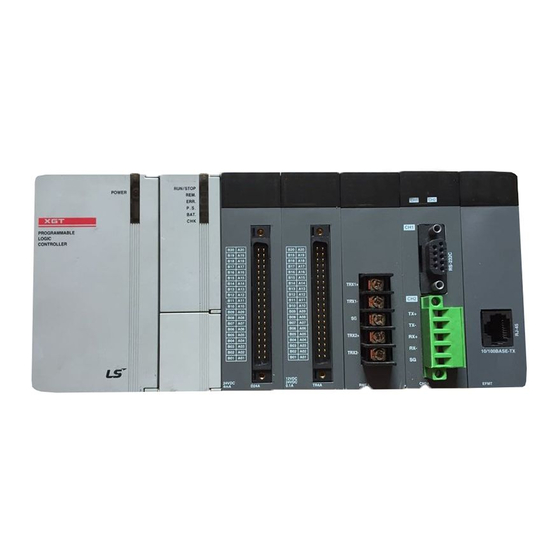
Motion Control Module
User's Manual
XGF-M32E
www.lsis.com
Advertisement
Table of Contents

Related Manuals for LSIS XGT Series


Summary of Contents for LSIS XGT Series
- Page 1 Right choice for ultimate yield LSIS strives to maximize customers' profit in gratitude of choosing us for your partner. Programmable Logic Controller Motion Control Module XGT Series User’s Manual XGF-M32E Read this manual carefully before installing, wiring, operating, servicing or inspecting this equipment.
- Page 2 Safety Instruction Before using the product … For your safety and effective operation, please read the safety instructions thoroughly before using the product. ► Safety Instructions should always be observed in order to prevent accident or risk with the safe and proper use the product. ►...
- Page 3 Safety Instruction Safety Instructions when designing Warning Please, install protection circuit on the exterior of PLC to protect the whole control system from any error in external power or PLC module. Any abnormal output or operation may cause serious problem in safety of the whole system.
- Page 4 Safety Instruction Safety Instructions when designing Caution I/O signal or communication line shall be wired at least 100mm away from a high-voltage cable or power line. If not, it may cause abnormal output or operation. Safety Instructions when designing Caution ...
- Page 5 Safety Instruction Safety Instructions when wiring Warning Prior to wiring, be sure that power of PLC and external power is turned off. If not, electric shock or damage on the product may be caused. Before PLC system is powered on, be sure that all the covers of ...
- Page 6 Safety Instruction Safety Instructions for test-operation or repair Warning Don’t touch the terminal when powered. Electric shock or abnormal operation may occur. Prior to cleaning or tightening the terminal screws, let all the external power off including PLC power. If not, electric shock or abnormal operation may occur.
- Page 7 4. Chapet 06 Motion function block example added 8-44~8-56, 8-72~8-103 5. Chapet 08 Functions’s explanation & example added ※ The num ber of User’ s m anual is indicated right part of the back cover. ⓒ LSIS Co., Ltd 2016 All Rights Reserved.
-
Page 8: Table Of Contents
Table of Contents ◎ Table of Contents ◎ Chapter 1 Overview………………………….......………………...……………………… 1-1 ~ 1-10 1.1 Characteristics ............................1 - 1 1.2 Signal Flow of Positioning Module ......................1 - 3 1.3 Function Overview of Motion Control module ....................1 - 4 1.3.1 Positioning Control ...........................1 - 4 1.3.2 Interpolation Control ........................1 - 5 1.3.3 Speed Control ..........................1 - 9 1.3.4 Torque Control ..........................1 - 10... - Page 9 Table of Contents 4.4.1 What is EtherCAT ...........................4 - 8 4.4.2 COE(CANopen over EtherCAT) ......................4 - 8 4.4.3 EtherCAT State Machine.........................4 - 9 4.4.4 EtherCAT Process Data Objective(PDO)..................4 - 10 4.4.5 Specification of Motion Control Module EtherCAT Communication ..........4 - 11 4.5 Motion Control Program .........................
- Page 10 Table of Contents 7.3.8 Parameter Write/Read ......................... 7 -18 7.4 Multi-Axis Operation Program .......................7 - 23 7.4.1 Linear Interpolation Operation ..................... 7 - 23 7.4.2 Circular Interpolation Operation ....................7 - 25 7.4.3 Synchronous Operation ....................... 7 - 27 7.4.4 CAM Operation ..........................7 - 30 7.4.5 Axis Group Processing ........................
- Page 11 Table of Contents Appendix 1 Error Information & Solutions ……………..........………………… A1-1~ A1-24 Appendix 2 Setting Example……………………………………………………………………....A2-1~ A2-21 Appendix 3 Dimension ……………………………………………………………………......A3-1...
-
Page 12: Chapter 1 Overview
Chapter 1 Overview Chapter 1 Overview This user’s manual describes the standard of Motion Control module, installation method, the method to use each function, programming and the wiring with external equipment. 1.1 Characteristics The characteristics of Motion Control module are as follows. (1) The Motion Control module is available for XGK/I/R Series. - Page 13 Chapter 1 Overview (4) Connection with the servo driver through EtherCAT (a) Direct connection to servo drives of up to 32 units and EtherCAT I/O of up to 4 units can be achieved through EtherCAT. (b) Since the connection between motion control module and servo drive is made using Ethernet cables. So wiring is simple.
-
Page 14: Signal Flow Of Positioning Module
Chapter 1 Overview 1.2 Signal Flow of Positioning Module The flow of PLC system using the Motion Control module is as follows. Writing sequence Program XG5000 PLC CPU Setting for control - Motion program - Operation parameter XG-PM - Cam data Encoder 1/2 - Servo parameter Motion Control module... -
Page 15: Function Overview Of Motion Control Module
Chapter 1 Overview 1.3 Function overview of Motion Control module Describe Representative functions of Motion Control module (Coordinate & Linear Interpolation, Circular Interpolation & Stop) briefly. 1.3.1 Position Control Execute positioning control for the designated axis from starting position(current position) to goal position(the position to move to). -
Page 16: Positioning Control
Chapter 1 Overview [ Example ] Starting Position : 5000 Target Position : -7000 In this condition, it moves reversely and stops at -2000. -2000 5000 Reverse positioning control(movement value -7000) Target position Starting Positon 1.3.2 Interpolation Control (1) Linear Interpolation Control Execute Linear interpolation control with designated axis at start position (Current position). - Page 17 Chapter 1 Overview (Y axis) Starting position 4000 Y axis movement value (1000-4000=-3000) Target 1000 position X axis 1000 5000 10000 X axis movement value (10000-1000=9000) (b) Linear Interpolation by incremental coordinates 1) Goal value becomes movement value 2) Moving direction depends on movement value is positive or negative. a) Positive value (+ or 0) : Positioning operation with forward direction b) Negative value (-) : Positioning operation with reverse direction Y axis Forward direction...
- Page 18 Chapter 1 Overview (2) Circular Interpolation Control Execute interpolation operation along the trace of circle with 2 axes in forward direction that already designated for each axis. Circular interpolation has 3 types according to auxiliary point, Middle point method passing auxiliary point, Center point method using auxiliary point as center of circle and Radius method using auxiliary point as radius of circle.
- Page 19 Chapter 1 Overview 2) If the goal position is same as starting position, it is available to have an operation like a circle that has distance from starting point to auxiliary point as its radius. Forward Direction Operating by circular interpolation Center point of the circle Start point...
-
Page 20: Speed Control
Chapter 1 Overview (3) Helical Interpolation (a) Moves along the designated trace of circular arc depending on circular arc interpolation setting and executes Linear interpolation synchronously. (b) There is no limit to the combination of axes to be used in helical interpolation, and three axes from actual axis (1 axis to 32 axes) or virtual axis (37 axes to 40 axes) are used. -
Page 21: Torque Control
Chapter 1 Overview (3) Operating Timing Speed Time Operation Command Operation It will not be ON even though stop Signal of positioning complete Stop command 1.3.4 Torque Control (1) The execution is made by the torque control command, and the operation is done in the set torque until the buffer command or stop command is entered. -
Page 22: Chapter 2 Specification
Chapter 2 Specifications Chapter 2 Specifications 2.1 General Specifications The following table shows the general specification of XGT series. Related Item Specifications specifications Ambient 0 ~ 55 °C temperature Storage −25 ~ +70 °C temperature Ambient 5 ~ 95%RH (Non-condensing) -
Page 23: Performance Specifications
Chapter 2 Specifications 2.2 Performance Specifications The following table shows the performance specifications of XGT Positioning Module. 2.2.1 Function Specifications Items Specification No. of control axis 32 axis(Real axis), 4 axis(Virtual axis), 4 axis(EtherCAT I/O) Communication EtherCAT (CoE: CANopen over EtherCAT) Communication period 1ms, 2ms, 4ms (Same with main task period) Servo drive... -
Page 24: Communication Specifications
Chapter 2 Specifications Items Specification Communication cable Over CAT.5 STP(Shielded Twisted-pair) cable Error indication Indicated by LED Communication status Indicated by LED indication Occupied point I/O Variable: 16points, Fixed: 64points Consumable current 900mA Weight 122g Note LREAL range: -1.7976931348623157e+308 ~ -2.2250738585072014e-308 or 0 or 2.2250738585072014e-308 ~ 1.7976931348623157e+308 Jerk: Change rate of acceleration, which is index, how fast acceleration increasing or decreasing 2.2.2 Communication specifications... -
Page 25: Internal Input/Output Specifications
Chapter 2 Specifications 2.2.3 Internal input/output specifications 1. Input specifications (source/sink type) Item Specification Input point 8 point Insulation method Photo-coupler insulation Rated input voltage Rated output voltage About 4mA Used voltage range DC20.4V~28.8V(within ripple rate 5%) On voltage/On current DC19V or above / 3mA or above Off voltage/Off current DC11V or less / 1.7mA or less... -
Page 26: Encoder Input Specifications
Chapter 2 Specifications 2.2.4 Encoder Input Specification Item Specification Input voltage 5V (4.5V ~ 5.5V) 7 ㎃ ~ 11 ㎃ Input current In accordance with RS-422A Line Driver Level Min. On guarantee 4.1V voltage Max. Off guarantee 1.7V voltage 1) Pulse width Over 2.5㎲... -
Page 27: The Name Of Each Part
Chapter 2 Specifications 2.3 The Name of Each Part 2.3.1 The name of each part ○ ○ ○ ○ ○ ○ Name Description On: Positioning module normal status ① Module ready(RDY) Off: Power OFF or CPU module reset status On: Run user program ②... -
Page 28: Specification Of Interface With External Device
Chapter 2 Specifications 2.3.2 Specification of interface with external device 1. Pin arrangement of connector Pin arrangement Pin no. Signal name Signal direction ENC1A+ Encoder 1A+ input ENC1A- Encoder 1A- input Input ENC1B+ Encoder 1B+ input ENC1B- Encoder 1B- input 5 –... - Page 29 Chapter 2 Specifications 2. Encoder internal circuit Item Pin No. Signal *Note1 ENC1A+ Encoder 1A+ input ENC1A- Encoder 1 A- input DC5V ENC1B+ Encoder 1 B+ input ENC1B- Encoder 1 B- input *Note2 ENC2A+ Encoder 2 A+ input ENC2A- Encoder 2 A- input DC5V ENC2B+ Encoder 2 B+ input...
- Page 30 Chapter 2 Specifications 3. Input internal circuit DC3.3V Internal 내부회로 Circuit DC24V 4. Output internal circuit DC3.3V Internal 내부회로 Circuit DC12/24V...
-
Page 31: Chapter 3 Operation Order And Installation
Chapter 3 Operation Order and Installation Chapter 3 Operation Order and Installation 3.1 Operation Order ▶ Here describes the Operation order of Motion Control module. Start Specify motion control operation method and control unit Specify the number of axis to be connected Specify the servo type and capacity External emergency stop signal Install the XG5000 and XG-PM on the PC... -
Page 32: Installation
Chapter 3 Operation Order and Installation 3.2 Installation 3.2.1 Installation Environment This machine has a good reliability regardless of installation environment but cares should be taken in the following items to guarantee the reliability and safety of the system. Environment Condition (1) Install the control panel available for water-proof, anti-vibration. -
Page 33: Notice In Wiring
Chapter 3 Operation Order and Installation 3.3 Notices in Wiring 3.3.1 Notices in Wiring (1) The length of connecting cable between positioning module and drive machine shall be as short as possible. (Max. length: 2m and 10m). (2) For alternating current and external I/O signal of positioning module, it is required to use the separate cables to avoid the surge or induction noise generated from the alternating current. -
Page 34: Connection Example Of Servo And Stepping Motor Drive Machine
Chapter 3 Operation Order and Installation 3.3.2 Connection Example of Servo and Stepping Motor Drive Machine (1) This is an example of wiring which connects EtherCAT servo drive/motor, the XDL-L7N Model of XGT Servo, in motion control module (XGF-M32E). Refer to manual of each drive for details on installation and wiring. - Page 35 Chapter 3 Operation Order and Installation Note *Note1 Wiring of encoder 1 is an example about 5V voltage output (open collector) type. *Note2 Wiring of encoder 2 is an example about 5V voltage output (line driver) type. *Note3 When connecting more than 2 servo drivers, connect first servo driver’s IN to the positioning module’s OUT and for other servo drivers, connect previous servo driver’s OUT to next servo driver’s IN.
- Page 36 Chapter 3 Operation Order and Installation (2) This is wiring example connecting SanMotion R Advanced Model EtherCAT servo drive/motor to Motion Control module(XGF-M32E). For detail on installation and wiring, refer to the driver manual. Servo Motor SanMotion R Advanced Model *Note4 with EtherCAT Coe Interface Power AC...
- Page 37 Chapter 3 Operation Order and Installation (3) This is wiring example connecting BeckHoff AX2000 servo drive/motor to Motion Control module (XGF-M32E). For detail on installation and wiring, refer to the driver manual. AX2000-B110 EtherCAT Drive Servo Motor Power AC 200~230V 50/60Hz *주4 BRAKE+...
-
Page 38: Encoder Input (Dc 5V Voltage Output) Wiring Example
Chapter 3 Operation Order and Installation 3.3.3 Encoder Input (DC 5V Voltage Output) Wiring Example When Pulse Generator is a Voltage Output type, wiring example of positioning module and Encoder input part is as follows. In case pulse generator is totem-pole output and used as voltage output style, wiring is equal. XGF-M32E Twisted shielded cable OUTA... -
Page 39: Encoder Input (Dc 5V Line Driver Output) Wiring Example
Chapter 3 Operation Order and Installation 3.3.4 Encoder Input (5V Line Driver Output) Wiring Example XGF-M32E Twisted shielded cable OUTA+ A phase + OUTA- A phase - OUTB+ B phase + OUTB- B phase - 5 V DC Notes Before Wiring, please consider maximum output distance of pulse generator. - Page 40 Chapter 3 Operation Order and Installation 3.3.5 External Input Signal Wiring Example 3.3.6 External Output Signal Wiring Example 3-10...
-
Page 41: Chapter 4 Motion Control Operation
Chapter 4 Motion Control Operation Chapter 4 Motion Control Operation This chapter describes structure, parameter and device of Motion Control module. Structure of Motion Control Module This picture describes process of parameter and operation data saved in the module. 【 XGS COU 】 XG5000 Seruende program XH-PM I/G... -
Page 42: Configuration Of Motion Control
Chapter 4 Motion Control Operation 4.2 Configuration of Motion Control XGF-M32E is motion control module of XGK/I/R series; it can control up to 32 axes of actual motor axis and 4 virtual axes through EtherCAT. Also, it can control up to 4 EtherCAT I/Os besides 8 points of input and 8 points of output included inside. -
Page 43: Motion Control Task
Chapter 4 Motion Control Operation Motion Control Tasks The following describes tasks of the motion control module. 4.3.1 Types of Tasks There are 3 types of motion control tasks: main task, periodic task and initialization task. The main task completes the motion within the period set by the user, and it performs I/O refresh, program process, motion control and processes EtherCAT synchronous communication. - Page 44 Chapter 4 Motion Control Operation Note 1. If main task period exceeds setting range, an error 0x0051 occurs. 2. If periodic task period is not set to a multiple of the main task period, an error 0x0052 occurs. 3. Please check the task period if the above errors occur. 4.3.2 Task Operation Overall task operation The task is composed of the main task and periodic task.
- Page 45 Chapter 4 Motion Control Operation (2) Performance time of main task > Main task period Main task period Main task period Main task period Performace time Performance time to main task to main task System management Perform Perform Output Input Output Input Processing...
- Page 46 Chapter 4 Motion Control Operation (1) Performance time of periodic task ≤ Periodic task period Periodic task period Performance time to periodic task Processing Processing program1 program2 (2) Performance time of periodic task > Periodic task period Periodic task period Periodic task period Periodic task period Performance time...
-
Page 47: Execution Of Motion Commands
Chapter 4 Motion Control Operation 4.3.3 Execution of Motion Commands 1. Execution of motion commands in the main task Execution of motion instruction of the main task is shown in the figure below. The input value of the slave and the system parameters are updated by the I/O refresh motion of the main task, and based on this information, the program is processed and motion control motion is performed. -
Page 48: Ethercat Communication
Chapter 4 Motion Control Operation EtherCAT Communication The communication of EtherCAT(Ethernet for Control Automation Technology) is explained here. 4.4.1 What is EtherCAT EtherCAT is a high-performance industrial network system which uses Real-Time Ethernet based on the Ethernet developed by Beckhoff Company in Germany. EhterCAT is a communication between the master and the slave, and it provides a short communication cycle time by transmitting Ethernet Frame at a high speed between each nodes. -
Page 49: Ethercat State Machine
Chapter 4 Motion Control Operation Types of communication Communication time Contents Process Data Communication Synchronous servo drive position control data, input/output of (PDO Communication) (main task period) data, etc. Service Data Communication Asynchronous servo parameter reading/writing, servo error (SDO Communication) (in request) information reading, etc. -
Page 50: Ethercat Process Data Objective(Pdo)
Chapter 4 Motion Control Operation 4.4.4 EtherCAT Process Data Objective(PDO) The synchronous data communication in EtherCAT communication of motion control module occurs through process data object (PDO). There are two types of process data: TxPDO which is transmitted from the slave to motion control module, and RxPDO which is transmitted from motion control module to the slave. -
Page 51: Specification Of Motion Control Module Ethercat Communication
Chapter 4 Motion Control Operation 4.4.5 Specification of Motion Control Module EtherCAT Communication Item Specification Communication EtherCAT protocol Support specification CoE(CANopen over EtherCAT) Physical layer 100BASE-TX Communication speed 100Mbps Topology Daisy Chain Communication cable Over Cat. 5 STP(Shielded Twisted-pair) cable No. -
Page 52: Motion Control Program
Chapter 4 Motion Control Operation Motion Control Program 4.5.1 Program Execution 1. Configuration of the program Motion control program is composed of functional elements needed in performing certain controls and it is performed in the internal RAM of motion control module. The program is backed up in the flash memory. Programs with these functional elements are classified as follows. - Page 53 Chapter 4 Motion Control Operation 3. TEST mode This is a mode which does not perform the motion program calculation but executes the command performed in command window. (1) Processing when changing the mode STOP mode is changed to TEST mode, and every output data is maintained in Off state. (2) The contents of operation processing This executes the command performed in command window and performs EtherCAT communication.
-
Page 54: Chapter 5 Memory And Parameter, I/O Signal
Chapter 5 Memory and Parameter Chapter 5 Memory and Parameter, I/O Signal 5.1 Memory 5.1.1 Flag 1. Types of flags (1) System flag This flag indicates the motion, state, and information of motion control module. Variable Data Type Address Description _RUN BOOL %FX0... - Page 55 Chapter 5 Memory and Parameter Variable Data Type Address Description _T100MS BOOL %FX97 100ms cycle clock _T200MS BOOL %FX98 200ms cycle clock _T1S BOOL %FX99 1s cycle clock _T2S BOOL %FX100 2s cycle clock _T10S BOOL %FX101 10s cycle clock _T20S BOOL %FX102...
- Page 56 Chapter 5 Memory and Parameter (2) Motion flag The flag displayed following are as follows. It displays the state and data of the Motion Control. The flag related to axis is displayed as “_AXxx_...”(xx indicates the relevant axis No.) and the flag related to axis group is displayed as “_AGxx_...”(xx indicates the axis group No.: 01 ~ 40).
- Page 57 Chapter 5 Memory and Parameter Variable Type Address Comment _AXxx_SVON_INCMPL BOOL %JXxx.16 Axis xx servo on incomplete _AXxx_COMM_WARN BOOL %JXxx.17 Axis xx communication warning _AXxx_DEV_WARN BOOL %JXxx.18 Axis xx abnormal deviation warning _AXxx_SV_ERR BOOL %JXxx.32 Axis xx servo drive error _AXxx_HW_POT BOOL %JXxx.33...
- Page 58 Chapter 5 Memory and Parameter Variable Type Address Comment _AXxx_Disabled BOOL %JXxx.80 Axis xx Disabled state _AXxx_Standstill BOOL %JXxx.81 Axis xx Standstill state _AXxx_Discrete BOOL %JXxx.82 Axis xx Discrete state _AXxx_Continuous BOOL %JXxx.83 Axis xx Continuous state _AXxx_Synchronized BOOL %JXxx.84 Axis xx Synchronized state _AXxx_Homing BOOL...
- Page 59 Chapter 5 Memory and Parameter Variable Type Address Comment Axis group xx state of motion commands _AGyy_PAUSE BOOL %CXyy.17 pause(velocity is zero) _AGyy_STOP BOOL %CXyy.18 Axis group xx stop state by the stop command _AGyy_FAIL BOOL %CXyy.19 Axis group xx command error exit status _AGyy_CMPL BOOL %CXyy.20...
- Page 60 Chapter 5 Memory and Parameter (3) I/O Flag The input/output flag indicates the embedded digital input and output values with embedded encoder values. In add, it indicates the PDO Data that is connected to the Motion Control Module under fixed-time communication. The below example displays the synchronized communication data flag when it is connected to L7N Servo Drive.
-
Page 61: Device
Chapter 5 Memory and Parameter 5.1.2 Device 1. Types of devices Types of device supported in motion control module are shown in the Table below. Type Size Description This is assigned when adding symbolic variable to automatic Automatic variable (A) 512KB variable area. - Page 62 Chapter 5 Memory and Parameter Number Description Size prefix X(1 bit), B(1 byte), W(1 word), D(1 double word), L(1 long word) 0: internal input and internal encoder input 1~36: slave number (TxPDO of n1 slave parameter is mapped) n2 data based on [size prefix] among n1 data ...
- Page 63 Chapter 5 Memory and Parameter Variable Data Type Address Description _SL3_Statusword UINT %IW3.0 Statusword _SL3_Torque_Actual_Value %IW3.1 Actual torque value _SL3_Position_Actual_Value DINT %ID3.1 Actual position value _SL3_Following_Error_Actual_Value DINT %ID3.2 Following error’s actual value _SL3_Digital_Inputs UDINT %ID3.3 Digital input _SL3_Mode_of_Operation_Display SINT %IB3.16 Operation mode display _SL3_Command_Speed(rpm) %IW3.9...
- Page 64 Chapter 5 Memory and Parameter When EtherCAT I/O (digital input 16 points, digital output 16 points) is added in 33-axes 5-11...
- Page 65 Chapter 5 Memory and Parameter (4) Output variable This is a variable which is assigned to built-in digital output. Internal digital output is 8 points. Output variable is expressed as follows. %I[size prefix]n1.n2 Number Description Size prefix X(1 bit), B(1 byte), W(1 word), D(1 double word), L(1 long word) 0: internal output 1~36: slave number (TxPDO of n1 slave parameter is mapped)
- Page 66 Chapter 5 Memory and Parameter Variable Data Type Address Description _SLx_Controlword UINT %QWx.0 Controlword _SLx_Target_Torque %QWx.1 Target torque _SLx_Target_Position DINT %QDx.1 Target position _SLx_Mode_of_Operation USINT %QBx.8 Operation mode _SLx_Touch_Probe_Function UINT %QWx.5 Touch probe function (5) System variable It is a variable that represents the operation status of module and motion control status. ...
- Page 67 Chapter 5 Memory and Parameter You can set the position values by selecting the position data in XG-PM project tree as below. 2. Retain setting Default (automatic) variable retain is used when wanting to keep and use the data that occurs while operating or the data required for an operation even in the case of restarting after the motion control module has stopped, and a certain part of the device in G area can be used as retain area by setting the basic parameter.
-
Page 68: Parameter
Chapter 5 Memory and Parameter 5.1.3 Parameter 1. Basic parameter Explain Basic parameter of the motion control module. (1) Basic motion setting (a) Main task cycle - Set the motion period of the main task. The period can be set by selecting one in 1ms/2ms/4ms. - Set the control time of performing in the main task of motion control module considering the execution timeof program. - Page 69 Chapter 5 Memory and Parameter Cold Restart Warm Restart Default Initialize with ‘0’ ‘Initialize with ‘0’ Retain Initialize with ‘0’ Maintain previous value Initialization Initialize with user setting value Initialize with user setting value Retain & Initialization Initialize with user setting value Maintain previous value (d) Output control setting When an error occurs in module or changing the motion mode of module, decide whether to maintain the data output...
- Page 70 Chapter 5 Memory and Parameter 2. Shared variable parameter 1) Sharing variable parameter is explained as follows. (a) Data are shared between CPU and motion control module by using the exclusive shared variable. (b) User can set the size of reading/writing by parameter, and the maximum setting size is 2,048 words each. (c) User can select and set motion control module in I/O parameter of XG5000.
- Page 71 Chapter 5 Memory and Parameter 3. Common parameter Common parameter is explained as follows. Item Description Settings Initialize value 0: pulse 1: mm Encoder1 Unit Set display unit of encoder position. 0: pulse 2: inch 3:degree Encoder1 Pulses per rotation Set Encoder1 pulses per rotation 1 ~ 4294967295 8192 pls...
- Page 72 Chapter 5 Memory and Parameter (1) Encoder unit This is to set the display unit of encoder position, and each control target can be set by pulse, mm, inch, and degree. In case of the synchronous operation having the encoder as a center, the unit must be set by the same unit with it of the synchronous operation axis.
- Page 73 Chapter 5 Memory and Parameter Add/Subtraction A phase input pulse High A phase input pulse Low B phase input pulse High Subtraction count B phase input pulse Low Add count (b) PULSE/DIR (x1) Count operation is performed when A phase input pulse increases, whether to be added or subtracted is decided by B phase.
- Page 74 Chapter 5 Memory and Parameter Add/Subtraction A phase input pulse High A phase input pulse Low B phase input pulse Off Add count Add count B phase input pulse On Subtraction count Subtraction count (d) PHASE A/B (x1) Add operation is performed in case of the increase in A phase pulse when the phase of A phase input pulse is ahead of B phase input pulse, and subtraction operation is performed in case of the decrease in A phase pulse when the phase of B phase input pulse is ahead.
- Page 75 Chapter 5 Memory and Parameter (f) PHASE A/B (x4) Count operation is performed in case of the increase/decrease in A phase input pulse and the increase/decrease in B phase; and add operation is performed when the phase of A phase is input ahead of B phase; and subtraction operation is performed when the phase of B phase is input ahead of A phase.
- Page 76 Chapter 5 Memory and Parameter 4. Axis group parameter Axis group parameter item is explained as follows. Item Description Settings Initial value Axis1 None None, Axis 2 None Set the axis which form axis group. 1Axis ~ 32Axis(real axis), Axis 3 None 37Axis ~ 40Axis(virtual axis) Axis 4...
- Page 77 Chapter 5 Memory and Parameter 5. Coordinate system parameter Coordinate system parameter is explained as follows. Part Description Setting range Initial value 0: None Coordinate Set the type of robot that is applied in the 1: XYZ 0: None system operation of coordinate system.
- Page 78 Chapter 5 Memory and Parameter 6. Tool setting parameter Tool setting parameter is explained as follows. Part Description Setting range Initial value Set the X axis offset of the end (tool) of the X axis offset LREAL robot. Set the Y axis offset of the end (tool) of the Y axis offset LREAL robot.
- Page 79 Chapter 5 Memory and Parameter (2) Cylinder Parameter Value Workspace parameter 1 Radius(mm) Z Axis Radius Workspace parameter 2 Z min(mm) Workspace parameter 3 Z max(mm) X Axis (3) Delta Parameter Value Z Axis YAxis Workspace parameter 1 Zu(mm) Workspace parameter 2 Hcy(mm) Workspace parameter 3 Hco(mm)
- Page 80 Chapter 5 Memory and Parameter 8. PCS parameter PCS parameter is explained as follows. Part Description Setting range Initial value X axis movement Set the X axis movement distance from LREAL 0 mm value the home position of MCS to that of PCS. Y axis movement Set the Y axis movement distance from LREAL...
- Page 81 Chapter 5 Memory and Parameter ‘0:Don’t check’ The communication connection process is continued while not comparing the Revision information set in the slave parameter and the Revision information which the slave has. ‘1: Check’ Compare the Revision information set in the slave parameter and the Revision information which the connected slave has, and if it does not correspond, a network configuration mismatch error (error code: 0x0F1F) occurs and ends the communication connection process.
- Page 82 Chapter 5 Memory and Parameter The setting items for the slave parameter are as follows. Item Description Settings Initial value Select the slave and displays the name of Slave name selected slave. Set the number of station which is applied to 1 ~ 32 Number (Increase automatically...
- Page 83 Chapter 5 Memory and Parameter ⑤ RxPDO Set the synchronous data which is transmitted from the motion control module to the slave in every communication period. RxPDO item supported by the relevant slave is automatically set when selecting a slave. Object that the user wants can be added or deleted by using the editing function.
- Page 84 Chapter 5 Memory and Parameter (3) Operation parameter (a) Basic parameter Basic parameter among operation parameters is explained as follows. Item Description Settings Initial value 0: pulse 1: mm Unit Set the command position unit of the axis. 0: pulse 2: inch 3:degree Set the number of pulses per rotation of motor...
- Page 85 Chapter 5 Memory and Parameter inch, and degree can be set for each axis. When changing the setting of the unit, other parameters or variable values are not changed. Therefore, when changing the units, the relevant parameters must be reset so that they can be adjusted to the setting range of the relevant unit.
- Page 86 Chapter 5 Memory and Parameter In case the operation speed of the serve axis exceeds the speed limit in synchronized operation. (gear, cam) In case the setting for「error level of tracking error」is ‘1: alarm’ and the error of tracking error occurs. ...
- Page 87 Chapter 5 Memory and Parameter Note If the unit from above ‘Setting example’ is set to ‘0’, it is moved to by a position corresponding to the encoder pulse, regardless of the motor and machine gear ratio. In other words, in order to move the 10mm it must make a command of the 524288 * 7/5 = 734003 pulse. ⑨...
- Page 88 Chapter 5 Memory and Parameter (b) Extended parameter The following explains extended parameter of operation parameter Item Description Settings Initial value S/W upper limit 2147483647 pls Set the range of the software limit functions. Long real(LREAL) S/W lower limit -2147483648 pls Set the value of the repetitive position range Long real(LREAL) Infinite running repeat position...
- Page 89 Chapter 5 Memory and Parameter The range check of the software upper limit and lower limit is conducted at the beginning of operation and during the operation. If the soft upper limit and lower limit is detected, an error occurs and the module suddenly stops a motor. Therefore, check the cause of the error and use it after resetting the error when restarting the operation.
- Page 90 Chapter 5 Memory and Parameter ⑤ Exceeding value of tracking error Set the value which will detect the value over position deviation. If a value exceeds this range, the 「Over deviation warning (_AXxx_DEV_WARN)」 or 「Over deviation alarm(_AXxx_DEV_ERR)」flag is On. If this set value is 0, it won’t detect the value over the deviation. You can set whether you want it to be a warning or an alarm for over deviation in the 「Error level of tracking error」of the expanded parameter.
- Page 91 Chapter 5 Memory and Parameter ■ Current position compensation amount = 50 pls If the current position value is within ±50 of command position after the end of operation, it is displayed as the command position value. . 5-38...
- Page 92 Chapter 5 Memory and Parameter ■ Current position compensation amount = 100 pls If the current position value is within ±100 of command position after the end of operation, it is displayed as the command position value. ⑧ Current speed filter time constant Set the time to calculate the average of movement at current speed.
- Page 93 Chapter 5 Memory and Parameter ■ Current speed filter time constant = 50 ms ■ Current speed filter time constant = 100 ms ⑨ Error reset monitoring time Set the monitoring time in the event of error reset occurred in the servo drive. (unit: ms) If the error which occurred in the servo drive within the error reset monitoring time, error reset monitoring is terminated and error reset time out error of servo drive (error code: 0x1070) is occurred.
- Page 94 Chapter 5 Memory and Parameter Even when the parameter value is set to '1: detect', if the software upper limit/lower limit is set to the initial value (upper limit: 2,147,483,647, lower limit: -2,147,483,648) or the same value, software limit is not detected. ⑪...
-
Page 95: I/O Signal
Chapter 5 Memory and Parameter 5.2 I/O signal Explain about the contents and functions of the I/O signal for data exchange of Motion control module and XGK CPU module. 5.2.1 Contents of I/O Signal 1. I/O Signal of Motion control module use input 48Bit, output 16bit. 2. - Page 96 Chapter 5 Memory and Parameter 5. Input signal The signal delivers from Motion control module to PLC CPU. Signal direction: Motion Control Module → PLC CPU Output Axis Description Signal RUN/STOP state Common Uxx.00.0 (0:RUN, 1:STOP) Common Uxx.00.1 Error state Common Uxx.00.2 Communication state...
-
Page 97: Use Of I/O Signal
Chapter 5 Memory and Parameter 5.2.2 Use of I/O Signal 1. Ready signal of axis operation (1) Ready signal of axis operation use EtherCAT communication to motion control module. Signal related to the connected axis is on when connecting servo drive. (2) Can check the axis which is accessed to motion control module and performs EtherCAT communication. -
Page 98: Chapter 6 Function Blocks
Chapter 6 Function Blocks Chapter 6 Function Blocks This chapter describes the basic function block library mentioned in the previous chapter and other application function block library. 6.1 Common Elements of Motion Function Blocks 6.1.1 The State of axis Each axis in the motion control module is changed to the relevant state depending on the situation and command. The changing structure of each situation is shown in the figure below. - Page 99 Chapter 6 Function Blocks The state of axis Description Disabled state indicates the state in which no command is given to a single axis, and no error occurs. In case there is no motion control module at the time of first operation, each axis begins in the disabled state.
-
Page 100: The State Of Group
Chapter 6 Function Blocks 6.1.2 The State of Group Each group in motion control module is changed to the relevant state depending on the situation and command. The changing structure of each state is shown in the figure below. MC_GroupHalt GroupMoving MC_GroupStop Error... -
Page 101: Basic I/O Variable
Chapter 6 Function Blocks 6.1.3 Basic I/O Variable 1. Edge operation motion function block Relationships of the basic I/O parameter in the Edge operation motion function block are as below. Execute Busy Active Done Error CommandAborted Variable Description This is an input to run the relevant function block in Edge operation function block. Execute Function block is executed in the rising Edge. - Page 102 Chapter 6 Function Blocks Variable Description This outputs error code regarding the relevant error when an error occurs while running ErrorID motion function block. ErrorID output and elimination time are same with Error output. This indicates the relevant motion function block is interrupted by the other motion function block.
- Page 103 Chapter 6 Function Blocks Variable Description This is an output to indicate an error occurs while running motion function block. If an error which cannot be automatically restored occurs while motion function block is in operation, Error output is On, Busy & Valid output is Off (Figure d state), and motion function block stops operating.
-
Page 104: Buffermode Input
Chapter 6 Function Blocks 6.1.4 BufferMode Input This is an input which can specify whether to wait until the existing command is completed or to cancel the existing motion function block and execute the command in case the axis is already running other motion function block when running motion function block in a certain axis. -
Page 105: Group Operation Route Change Settings
Chapter 6 Function Blocks SlaveOffset, MasterScaling, and SlaveScaling are updated. ) (6) For MC_GEARIN function block, only the following inputs can be updated: RatioNumerator, RatioDenominator, Acceleration, and Deceleration (If InGear=On, only RatioNumerator and RatioDenominator are updated.) 6.1.6 Group Operation Route Change Settings When the axis group of the current motion control module is executing a command, other command can be issued to the relevant axis group. - Page 106 Chapter 6 Function Blocks The Figure below shows that the case when running BufferMode of motion function block in the setting of ‘Buffered’. The Figure in the left shows that motion function block ② is executed in the setting of 'Buffered’ while motion function block ①...
- Page 107 Chapter 6 Function Blocks <In case BufferMode is specified as “BlendingLow” and TransitionMode is specified as “TMCornerDistance”> 6-10...
-
Page 108: Motion Function Block Errors
Chapter 6 Function Blocks 6.1.7 Motion Function Block Errors Errors occurring in ErrorID variable of motion function block are as follows. STAT Content Detailed Description In case motion function block is normally executed, “O” is 0x0000 Normal displayed on ErrorID. The motion function block is not executed in the version of The current motion module does not support the 0x0005... -
Page 109: Motion Function Block
Chapter 6 Function Blocks 6.2 Motion Function Block Movement Name Description Condition Single-axis Motion Command MC_Power Servo On/OFF Level MC_Home Perform the search home Edge MC_Stop Stop immediately Edge MC_Halt Stop Edge MC_MoveAbsolute Absolute positioning operation Edge MC_MoveRelative Relative positioning operation Edge MC_MoveAdditive Additive positioning operation... - Page 110 Chapter 6 Function Blocks Movement Name Description Condition Removes one axis to a group in a structure 25 MC_RemoveAxisFromGroup Edge AxesGroup 26 MC_UngroupAllAxes Removes all axes from the group AxesGroup Edge Changes the state for a group from GroupDisabled to 27 MC_GroupEnable Edge GroupEnable...
-
Page 111: Single-Axis Motion Function Blocks
Chapter 6 Function Blocks 6.3 Single-Axis Motion Function Block 6.3.1 Servo on/off (MC_Power) Motion Function Block MC_Power BOOL Enable Status BOOL UINT Axis Axis UINT Vaild BOOL Error BOOL ErrorID WORD Input-Output UINT Axis Specify the axis to be commanded (1~32: real axis, 37~40: virtual axis) Input BOOL Enable... - Page 112 Chapter 6 Function Blocks 6.3.2 Perform the search home(MC_Home) Motion Function Block MC_Home BOOL Execute Done BOOL UINT Axis Axis UINT LREAL Position Busy BOOL UINT BufferMode Active BOOL CommandAborted BOOL Error BOOL ErrorID WORD Input-Output UINT Axis Specify the axis to be commanded (1~32: real axis, 37~40: virtual axis) Input BOOL Execute...
- Page 113 Chapter 6 Function Blocks (a) Function block setting (b) Parameter setting - Set the Homing method in SDO parameters to 33. (c) Timing diagram Position Velocity 6-16...
- Page 114 Chapter 6 Function Blocks 6.3.3 Stop immediately(MC_STOP) Motion Function Block MC_Stop BOOL Execute Done BOOL UINT Axis Axis UINT LREAL Deceleration Busy BOOL LREAL Jerk CommandAborted BOOL Error BOOL ErrorID WORD Input-Output UINT Axis Specify the axis to be commanded (1~32: real axis, 37~40: virtual axis) Input BOOL Execute...
- Page 115 Chapter 6 Function Blocks 6.3.4 Stop(MC_Halt) Motion Function Block MC_Halt BOOL Execute Done BOOL UINT Axis Axis UINT LREAL Deceleration Busy BOOL LREAL Jerk Active BOOL UINT BufferMode CommandAborted BOOL Error BOOL ErrorID WORD Input-Output UINT Axis Specify the axis to be commanded (1~32: real axis, 37~40: virtual axis) Input BOOL Execute...
- Page 116 Chapter 6 Function Blocks 6.3.5 Absolute positioning operation (MC_MoveAbsolute) Motion Function Block MC_MoveAbsolute Done BOOL Execute BOOL Axis UINT Axis UINT Busy BOOL ContinuousUpdate BOOL Active LREAL Position BOOL CommandAborted LREAL Velocity BOOL Error LREAL Acceleration BOOL ErrorID LREAL Deceleration WORD LREAL Jerk...
- Page 117 Chapter 6 Function Blocks the relevant axis doing Infinite length repetition operation automatically selects the direction which allows the shortest distance. The available range is 0-4 (0-Not specified, 1-Forward direction, 2-Shortest distance, 3-Reverse direction, 4-Current direction), and "error 0x1017” occurs in case of excess of the range. (3) On condition that there is no motion function block is on standby after the current motion function block, If the speed is 0 after reaching the target point, operation is completed and Done output is On.
- Page 118 Chapter 6 Function Blocks (7) Application example program This example shows the execution of another function block with BufferMode set to 1 while moving from the current command position of 50,000,000 to the 100,000,000 position, to move to the -100,000,000 position. (a) Function block setting (b) Timing diagram Position...
- Page 119 Chapter 6 Function Blocks 6.3.6 Relative positioning operation(MC_MoveRelative) Motion Function Block MC_MoveRelative BOOL Execute Done BOOL UINT Axis Axis UINT BOOL ContinuousUpdate Busy BOOL LREAL Distance Active BOOL LREAL Velocity CommandAborted BOOL LREAL Acceleration Error BOOL LREAL Deceleration ErrorID WORD LREAL Jerk UINT...
- Page 120 Chapter 6 Function Blocks moving to the target distance, operation is completed and Done output is On. (5) The axis is in "DiscreteMotion" state when this motion function block is running, and it is switched to "StandStill" state when operation is completed. (6) The changed parameters can be applied by re-executing the function block (Execute input is On) before the command is completed.
- Page 121 Chapter 6 Function Blocks (8) Application example program This example shows the execution of another function block with BufferMode set to 1 while moving from the current command position of 50,000,000 to the 150,000,000 position, to move to the 50,000,000 position. (a) Function block setting (b) Timing diagram Position...
- Page 122 Chapter 6 Function Blocks 6.3.7 Additive positioning operation(MC_MoveAdditive) Motion Function Block MC_MoveAdditive BOOL Execute Done BOOL UINT Axis Axis UINT BOOL ContinousUpdate Busy BOOL LREAL Distance Active BOOL LREAL Velocity CommandAborted BOOL LREAL Acceleration Error BOOL LREAL Deceleration ErrorID WORD LREAL Jerk UINT...
- Page 123 Chapter 6 Function Blocks the latest motion function block executed in 'DiscreteMotion' state. If the current axis is executing motion function block ‘ContinuousMotion’ state, it executes operation based on the position where additive position motion (MC_MoveAdditve) is executing. (3) Moving direction is decided depending on the sign of the specified target distance in Distance input, and positive (+ or No sign) moving direction leads to forward direction, and negative (-) moving direction leads to reverse direction.
- Page 124 Chapter 6 Function Blocks (8) Application example program This example shows the execution of MC_MOVEADDITIVE function block while moving from current command position of 0 to the 50,000,000 position, to move an additional 100,000,000 to the 150,000,000 position. (a) Function block setting (b) Timing diagram Position Velocity...
- Page 125 Chapter 6 Function Blocks 6.3.8 Specified velocity operation(MC_MoveVelocity) Motion Function Block MC_MoveVelocity BOOL Execute InVelocity BOOL UINT Axis Axis UINT BOOL ContinuousUpdate Busy BOOL LREAL Velocity Active BOOL LREAL Acceleration CommandAborted BOOL LREAL Deceleration Error BOOL LREAL Jerk ErrorID WORD UINT Direction UINT...
- Page 126 Chapter 6 Function Blocks (3) Specify the operation speed in Velocity input. Positive sign (+ or No sign) of the operation speed value leads to forward direction, and negative (-) sign leads to reverse direction. (4) Specify the operation direction in Direction input. But, the operation direction is affected by the sign of the specified speed value by Velocity input.
- Page 127 Chapter 6 Function Blocks (9) Application example program This example program shows that it stops running due to the execution of MC-Halt function block, while moving in the reverse direction at a velocity of 10,000,000. (a) Function block setting (b) Timing diagram Position Velocity 6-30...
- Page 128 Chapter 6 Function Blocks 6.3.9 Absolute position operation ending with specified velocity operation(MC_MoveContinuousAbsolute) Motion Function Block MC_MoveContinousAbsolute BOOL Execute InEndVelocity BOOL UINT Axis Axis UINT BOOL ContinousUpdate Busy BOOL LREAL Position Active BOOL LREAL EndVelocity CommandAborted BOOL LREAL Velocity Error BOOL LREAL Acceleration...
- Page 129 Chapter 6 Function Blocks (1) This motion function block is to give Specified velocity operation after relative position operation command to the relevant axis. (2) When executing MC_MoveContinuousAbsolute, the relevant axis moves to the position specified in Position and operates at the specified speed in EndVelocity if there is no motion function block is on standby. (3) Giving a stop command or execution of other motion function block allow to interrupt speed operation.
- Page 130 Chapter 6 Function Blocks (b) Timing diagram Velocity Position (9) Application example program This example program showsthe movement in the direction of the same speed when re-executing the function block after stopping the execution of MC-Halt function block, while moving from thecurrent command position of 0 to the 50,000,000, then operating at a speed of 20,000,000.
- Page 131 Chapter 6 Function Blocks (b) Timing diagram Position Velocity 6-34...
- Page 132 Chapter 6 Function Blocks 6.3.10 Relative position operation ending with specified velocity operation(MC_MoveContinuousRelative) Motion Function Block MC_MoveContinousRelative BOOL Execute InEndVelocity BOOL UINT Axis Axis UINT BOOL ContinousUpdate Busy BOOL LREAL Distance Active BOOL LREAL EndVelocity CommandAborted BOOL LREAL Velocity Error BOOL LREAL Acceleration...
- Page 133 Chapter 6 Function Blocks (2) When executing MC_MoveContinuousRelative, the relevant axis operates at the speed specified in EndVelocity after moving the distance specified in Distance if there is no motion function block is on standby. (3) Giving a stop command or operation of other motion function block allow to interrupt specified velocity motion. (4) Output InEndVelocity is On when the relevant axis starts speed operation and reaches the specified speed after moving the specified distance, and when specified velocity motion is interrupted, it is Off.
- Page 134 Chapter 6 Function Blocks (8) Application example program This example program shows the movement at a velocity of 20,000,000 after moving from the current command position of 0 to the 50,000,000 position, then operating at a velocity of 20,000,000, stopping by executing MC_Halt function block, moving to the same relative position (20,000,000) by re-executing the function block.
- Page 135 Chapter 6 Function Blocks 6.3.11 Torque control(MC_TorqueControl) Motion Function Block MC_TorqueControl BOOL Execute InTorque BOOL UINT Axis Axis UINT BOOL ContinousUpdate Busy BOOL LREAL Torque Active BOOL LREAL TorqueRamp CommandAborted BOOL LREAL Velocity Error BOOL LREAL Acceleration ErrorID WORD LREAL Deceleration LREAL Jerk...
- Page 136 Chapter 6 Function Blocks (1) This motion function block is to give torque control command to the relevant axis. (2) When executing torque control (MC_Torque), the relevant axis performs the control to keep the torque value specified in Torque input. (3) Giving a stop command or operation of other motion function block allow to interrupt specified velocity motion.
- Page 137 Chapter 6 Function Blocks 6.3.12 Setting the current position(MC_SetPosition) Motion Function Block MC_SetPosition BOOL Execute Done BOOL UINT Axis Axis UINT LREAL Position Busy BOOL BOOL Relative Error BOOL UINT ExcutionMode ErrorID WORD Input-Output UINT Axis Specify the axis to be commanded (1~32: real axis, 37~40: virtual axis) Input BOOL Execute...
- Page 138 Chapter 6 Function Blocks (4) Example program This example program shows the setting of the current position to 200,000,000 position by adding a relative position (Relative=1) corresponding to the set value (50,000,000) from the current position of 150,000,000. (a) Function block setting (b) Timing diagram Position 6-41...
- Page 139 Chapter 6 Function Blocks 6.3.13 Velocity/Acceleration override(MC_SetOverride) Motion Function Block MC_SetOverride BOOL Execute Enabled BOOL UINT Axis Axis UINT LREAL VelFactor Busy BOOL LREAL AccFactor Error BOOL LREAL JerkFactor ErrorID WORD Input-Output UINT Axis Specify the axis to be commanded (1~32: real axis, 37~40: virtual axis) Input BOOL Enable...
- Page 140 Chapter 6 Function Blocks (a) Function block setting (b) Timing diagram Velocity Position 6-43...
- Page 141 Chapter 6 Function Blocks 6.3.14 Read Parameter(MC_ReadParameter) Motion Function Block MC_ReadParameter BOOL Enable Vaild BOOL UINT Axis Axis UINT ParameterNumber Busy BOOL Error BOOL ErrorID WORD Value LREAL Input-Output UINT Axis Specify the axis to be commanded (1~32: real axis, 37~40: virtual axis) Input BOOL Enable...
- Page 142 Chapter 6 Function Blocks (4) The numbers of parameter are as below. Parameter Item Description Unit 0:pulse,1:mm,2:inch,3:degree Purses per rotation 1 ~ 4,294,967,295 [pulse] Travel per rotation 0.000000001 ~ 4,294,967,295 [Unit] Speed command unit 0:Unit/Time, 1:rpm LREAL Positive number [Unit/s, rpm] Speed limit (Change according to Unit, Pulses per rotation, Basic...
- Page 143 Chapter 6 Function Blocks Encorder1 unit 0: pulse, 1: mm, 2: inch, 3:degree Encorder1 pulse per rotation 1 ~ 4294967295 Encorder1 travel per rotation 0.000000001 ~ 4294967295 0:CW/CCW 1 multiplier, 1:PULSE/DIR 1 multiplier Encorder1 pulse input 2:PULSE/DIR 2 multiplier, 3:PHASE A/B 1 multiplier 4:PHASE A/B 2 multiplier, 5: PHASE A/B 4multiplier Encorder2 unit 0: pulse, 1: mm, 2: inch, 3:degree...
- Page 144 Chapter 6 Function Blocks 6.3.15 Write Parameter(MC_WriteParameter) Motion Function Block MC_WriteParameter BOOL Execute Vaild BOOL Axis UINT Axis UINT ParameterNumber Busy BOOL LREAL Value Error BOOL UINT ExcutionMode ErrorID WORD Input-Output UINT Axis Specify the axis to be commanded (1~32: real axis, 37~40: virtual axis) Input BOOL Execute...
- Page 145 Chapter 6 Function Blocks (6) The numbers of parameter are as below. Parameter Item Description Unit 0:pulse,1:mm,2:inch,3:degree Purses per rotation 1 ~ 4,294,967,295 [pulse] Travel per rotation 0.000000001 ~ 4,294,967,295 [Unit] Speed command unit 0:Unit/Time, 1:rpm LREAL Positive number [Unit/s, rpm] (Change according to Unit, Pulses per rotation, Speed limit Basic...
- Page 146 Chapter 6 Function Blocks Encorder1 unit 0: pulse, 1: mm, 2: inch, 3:degree Encorder1 pulse per rotation 1 ~ 4294967295 Encorder1 travel per rotation 0.000000001 ~ 4294967295 0:CW/CCW 1 multiplier, 1:PULSE/DIR 1 multiplier Encorder1 pulse input 2:PULSE/DIR 2 multiplier, 3:PHASE A/B 1 multiplier 4:PHASE A/B 2 multiplier, 5: PHASE A/B 4multiplier Encorder2 unit 0: pulse, 1: mm, 2: inch, 3:degree...
- Page 147 Chapter 6 Function Blocks 6.3.16 Reset axis error(MC_Reset) Motion Function Block MC_Reset BOOL Execute Done BOOL UINT Axis UINT Axis Busy BOOL BOOL ErrorType Error BOOL ErrorID WORD Input-Output UINT Axis Specify the axis to be commanded (1~32: real axis, 37~40: virtual axis) Input BOOL Execute...
- Page 148 Chapter 6 Function Blocks 6.3.17 Touch Probe(MC_TouchProbe) Motion Function Block MC_TouchProbe BOOL Execute Done BOOL Axis UINT Axis UINT UINT TriggerInput TriggerInput UINT BOOL WindowOnly Busy BOOL LREAL FirstPosition CommandAborted BOOL LREAL LastPosition Error BOOL ErrorID WORD RecordedPosition LREAL Input-Output UINT Axis Specify the axis to be commanded (1~32: real axis)
- Page 149 Chapter 6 Function Blocks Note In the case of using Touch Probe 2, please set the slave parameters before use. 1. At XG-PM, click the registration information of the servo drive. 2. Select Edit at the slave information window. 3. At the PDO edit window, select the forward direction position value for Touch Probe 2, and select the down arrow. For some servo drive, a PDO setting error (0xF22) may occur, preventing connection to the servo drive.
- Page 150 Chapter 6 Function Blocks < In case TouchProbe function is the window mode, Operation timing > 6-53...
- Page 151 Chapter 6 Function Blocks 6.3.18 Abort trigger events(MC_AbortTrigger) Motion Function Block MC_AbortTrigger BOOL Execute Done BOOL Axis UINT Axis UINT UINT TriggerInput TriggerInput USINT Busy BOOL Error BOOL ErrorID WORD Input-Output UINT Axis Specify the axis to be commanded (1~32: real axis) UINT TriggerInput Specify the trigger signal to be disengaged.
- Page 152 Chapter 6 Function Blocks 6.3.19 SuperImposed operation (MC_MoveSuperImposed) Motion Function Block MC_MoveSuperImposed BOOL Execute Done BOOL UINT Axis Axis UINT BOOL ContinuousUpdate Busy BOOL LREAL Distance Active BOOL LREAL VelocityDiff CommandAborted BOOL LREAL Acceleration Error BOOL LREAL Deceleration ErrorID WORD CoveredDistance LREAL LREAL...
- Page 153 Chapter 6 Function Blocks 6.3.20 SuperImposed operation halt (MC_HaltSuperImposed) 모션 펑션 블록 형태 MC_HaltSuperImposed BOOL Execute Done BOOL UINT Axis Axis UINT LREAL Deceleration Busy BOOL LREAL Jerk Active BOOL CommandAborted BOOL Error BOOL ErrorID WORD 입력-출력 UINT Axis Specify the axis to be commanded (1~32: real axis) 입력...
-
Page 154: Multi-Axis Motion Function Blocks
Chapter 6 Function Blocks 6.4 Multi-Axis Motion Function Block 6.4.1 Camming run(MC_CamIn) Motion Function Block MC_CamIn BOOL Execute InSync BOOL UINT Master Master UINT UINT Slave Slave UINT LREAL ContinousUpdate Busy BOOL LREAL MasterOffset Active BOOL LREAL SlaveOffset CommandAborted BOOL LREAL MasterScaling Error... - Page 155 Chapter 6 Function Blocks 1: Cam table is applied as a relative value based on the command starting point (mcRelative) Select the source of the main axis for cam operation. UINT MasterValueSource 0 : Synchronized in the target value of the main axis. 1 : Synchronized in the current value of the serve axis.
- Page 156 Chapter 6 Function Blocks (6) Set the magnification of cam data to be applied in MasterScaling and SlaveScaling. Set the magnification of the main axis data in MasterScaling, and set the magnification of the the serve axis data. Refer to the Figure below. After applying SlaveScaling = 2.0 SlaveScaling...
- Page 157 Chapter 6 Function Blocks MasterSyncPosition position is based on the position within the cam table, and actual synchronization position is decided by considering MasterOffset and MasterScale parameters. The serve axis starts moving to the synchronization position from the distance of the input value away based on the position where MasterSyncPosition is actually applied.
- Page 158 Chapter 6 Function Blocks (14) Example program This example shows the movement of the main-axis from 0 to 200,000 positions after generating a cam profile and then executing MC_CAMIN command on the sub-axis. (a) Function block setting 6-61...
- Page 159 Chapter 6 Function Blocks (b) Timing diagram Velocity Position (15) Application example program This example shows the movement of the main-axis from 0 to 200,000 positions after generating the same profile and then executing C_CAMIN command where MasterSyncPosition and MasterSyncDistance are set to 80,000 in sub-axis.
- Page 160 Chapter 6 Function Blocks (b) Timing diagram Master velocity Slave velocity Slave position Master position 6-63...
- Page 161 Chapter 6 Function Blocks 6.4.2 Camming stop(MC_CamOut) Motion Function Block MC_CamOut BOOL Execute Done BOOL Slave UINT Slave UINT Busy BOOL Error BOOL ErrorID WORD Input-Output UINT Slave Set the the serve axis. (1~32: Actual axes, 37~40: Virtual axes) Input BOOL Execute Give cam operation stop command to the relevant axis in the rising Edge.
- Page 162 Chapter 6 Function Blocks (a) Function block setting 6-65...
- Page 163 Chapter 6 Function Blocks (b) Timing diagram Master velocity Slave velocity Slave position Master position 6-66...
- Page 164 Chapter 6 Function Blocks 6.4.3 Electrical gearing run(MC_GearIn) Motion Function Block MC_GearIn BOOL Execute InGear BOOL UINT Master Master UINT UINT Slave Slave UINT BOOL ContinousUpdate Busy BOOL RatioNumerator Active BOOL UINT RatioDenominator CommandAborted BOOL UINT MasterValueSource Error BOOL LREAL Acceleration ErrorID WORD...
- Page 165 Chapter 6 Function Blocks Output BOOL InGear Indicate that gear operation is running by applying gear ration. BOOL Busy Indicate that the execution of motion function block is not completed. BOOL Active Indicate that the current motion function block is controlling the relevant axis. BOOL CommandAborted Indicate that the current motion function block is interrupted while it is running.
- Page 166 Chapter 6 Function Blocks (a) Function block setting (b) Timing diagram 1 Axis position 2 Axis position 1 Axis velocity 2 Axis velocity 6-69...
- Page 167 Chapter 6 Function Blocks 6.4.4 Electrical gearing disengage(MC_GearOut) Motion Function Block MC_GearOut BOOL Execute Done BOOL UINT Slave Slave UINT Busy BOOL Error BOOL ErrorID WORD Input-Output UINT Slave Set the the serve axis. (1~32: Actual axes, 37~40: Virtual axes) Input Specify the sequential operation setting of motion function block.
- Page 168 Chapter 6 Function Blocks (a) Function block setting (b) Timing diagram 2 Axis velocity 1 Axis velocity Red: 1Axis position Blue: 2Axis position 6-71...
- Page 169 Chapter 6 Function Blocks 6.4.5 Electrical gearing by specifying the position(MC_GearInPos) Motion Function Block Input-Output UINT Master Set the main axis. (1~32: Actual axes, 37~40: Virtual axes, 41~42: Encoders) UINT Slave Set the the serve axis. (1~32: Actual axes, 37~40: Virtual axes) Input BOOL Execute...
- Page 170 Chapter 6 Function Blocks Specify the maximum deceleration of the spindle at the beginning of LREAL Deceleration synchronization. [u/s LREAL Jerk Specify the change rate of acceleration/deceleration. [u/s Specify the sequential operation setting of motion function block. UINT BufferMode (Refer to 10.1.4.BufferMode) Output Indicate that gear operation is normally being fulfilled as the specified gear ratio is BOOL...
- Page 171 Chapter 6 Function Blocks (8) The changed parameters can be applied by re-executing the function block (Execute input is On) before the command is completed. Only RatioNumerator, RatioDenominator, MasterSyncPosition, SlaveSyncPosition, MasterStartDistance, Velocity, Acceleration, Deceleration input can be updated. (However, in case of InGear=On, RatioNumerator, RatioDenominator input can be updated.
- Page 172 Chapter 6 Function Blocks (a) Function block setting (b) Timing diagram 1 Axis velocity 2 Axis velocity 2 Axis position 1 Axis position 6-75...
- Page 173 Chapter 6 Function Blocks (10) Application example program This example program shows MC_GearInPos Active and InSync being off and gear operation being terminated when MC_GearOut command is issued on 2-axis at (a) position during the motion shown in the basic example program.
- Page 174 Chapter 6 Function Blocks 6.4.6 Phase compensation(MC_Phasing) Motion Function Block MC_Phasing BOOL Execute Done BOOL UINT Master Master UINT UINT Slave Slave UINT LREAL PhaseShift Busy BOOL LREAL Velocity Active BOOL LREAL Acceleration CommandAborted BOOL LREAL Deceleration Error BOOL LREAL Jerk ErrorID WORD...
- Page 175 Chapter 6 Function Blocks (2) Once phase correction command is executed, the current position of the main-axis is phase-corrected using the phase shift setting at PhaseShift- Velocity / Acceleration /Deceleration / Jerk. (3) Phase correction does not change the actual command position or current position of the main-axis. Phase correction is performed on the main-axis position referred to by sub-axis in synchronous control operation.
-
Page 176: Group Motion Function Blocks
Chapter 6 Function Blocks 6.5 Group Motion Function Blocks 6.5.1 Adds one axis to a group in a structure AxesGroup(MC_AddAxisToGroup) Motion Function Block MC_AddAxisToGroup BOOL Execute Done BOOL UINT AxesGroup AxesGroup UINT UINT Axis Axis UINT UINT IdentInGroup Busy BOOL Error BOOL ErrorID... - Page 177 Chapter 6 Function Blocks 6.5.2 Removes one axis to a group in a structure AxesGroup(MC_RemoveAxisFromGroup) Motion Function Block MC_RemoveAxisFromGroup BOOL Execute Done BOOL UINT AxesGroup AxesGroup UINT UINT IdentInGroup Busy BOOL Error BOOL ErrorID WORD Input-Output UINT AxesGroup Set the group where the relevant axis is removed. (1 ~ 16 : Group1 ~ Group 16) Input BOOL Execute...
- Page 178 Chapter 6 Function Blocks 6.5.3 Removes all axes from the group AxesGroup(MC_UngroupAllAxes) Motion Function Block MC_UngroupAllAxes BOOL Execute Done BOOL UINT AxesGroup AxesGroup UINT Busy BOOL Error BOOL ErrorID WORD Input-Output UINT AxesGroup Set the group where every axis is to be removed. (1 ~ 16 : Group 1 ~ Group 16) Input BOOL Execute...
- Page 179 Chapter 6 Function Blocks 6.5.4 Changes the state for a group from GroupDisabled to GroupEnable(MC_GroupEnable) Motion Function Block MC_GroupEnable BOOL Execute Done BOOL AxesGroup AxesGroup UINT UINT Busy BOOL Error BOOL ErrorID WORD Input-Output UINT AxesGroup Set the group to be activated. (1 ~ 16 : Group 1 ~ Group 16) Input BOOL Execute...
- Page 180 Chapter 6 Function Blocks 6.5.5 Changes the state for a group to GroupDisabled(MC_GroupDisable) Motion Function Block MC_GroupDisable BOOL Execute Done BOOL UINT AxesGroup AxesGroup UINT Busy BOOL Error BOOL ErrorID WORD Input-Output UINT AxesGroup Set the group to be deactivated. (1 ~ 16 : Group 1 ~ Group 16) Input BOOL Execute...
- Page 181 Chapter 6 Function Blocks 6.5.6 The AxesGroup to perform the search home sequence(MC_GroupHome) Motion Function Block MC_GroupHome BOOL Execute Done BOOL UINT AxesGroup AxesGroup UINT LREAL[ ] Position Busy BOOL UINT BufferMode Active BOOL CommandAborted BOOL Error BOOL ErrorID WORD Input-Output UINT AxesGroup...
- Page 182 Chapter 6 Function Blocks 6.5.7 Sets the Position of all axes in a group without moving(MC_GroupSetPosition) Motion Function Block MC_GroupSetPosition Execute Done BOOL BOOL UINT AxesGroup AxesGroup UINT Position Busy BOOL BOOL Relative Active BOOL UINT ExecuteMode CommandAborted BOOL Error BOOL ErrorID WORD...
- Page 183 Chapter 6 Function Blocks (rising Edge in Execute input). If the relevant axis is running, the operation can be affected. 1 (mcQueued): Changed at the same point of ‘Buffered’ of Buffermode (Error! Reference Source Not Found. Refer to input). (4) Example program This example shows the change of the current position to position values (10,000,000/20,000,000/30,000,000) set in the position variables when executing MC_GroupSetPosition function block at the status where 1-axis, 2- axis and 3-axis are set as a single group.
- Page 184 Chapter 6 Function Blocks 6.5.8 Stop a Group immediately(MC_GroupStop) Motion Function Block MC_GroupStop BOOL Execute Done BOOL UINT AxesGroup AxesGroup UINT LREAL Deceleration Busy BOOL LREAL Jerk Active BOOL CommandAborted BOOL Error BOOL ErrorID WORD Input-Output UINT AxesGroup Set the group to stop immediately. (1 ~ 16 : Group 1 ~ Group 16) Input BOOL Execute...
- Page 185 Chapter 6 Function Blocks 6.5.9 Stop a Group(MC_GroupHalt) Motion Function Block MC_GroupHalt BOOL Execute Done BOOL UINT AxesGroup AxesGroup UINT LREAL Deceleration Busy BOOL LREAL Jerk Active BOOL UINT BufferMode CommandAborted BOOL Error BOOL ErrorID WORD Input-Output UINT AxesGroup Set the group to stop. (1 ~ 16 : Group 1 ~ Group 16) Input BOOL Execute...
- Page 186 Chapter 6 Function Blocks 6.5.10 Reset a group error(MC_GroupReset) Motion Function Block MC_GroupReset BOOL Execute Done BOOL UINT AxesGroup AxesGroup UINT Busy BOOL Error BOOL ErrorID WORD Input-Output UINT AxesGroup Set the group to do error reset. (1 ~ 16 : Group 1 ~ Group 16) Input BOOL Execute...
- Page 187 Chapter 6 Function Blocks 6.5.11 Absolute positioning linear interpolation operation(MC_MoveLinearAbsolute) Motion Function Block MC_MoveLinearAbsolute Done BOOL Execute BOOL AxesGroup UINT AxesGroup UINT Busy LREAL[ ] Position BOOL Active LREAL Velocity BOOL CommandAborted LREAL Acceleration BOOL Error LREAL Deceleration BOOL ErrorID LREAL Jerk WORD...
- Page 188 Chapter 6 Function Blocks (1) This motion function block is to give an absolute position linear interpolation command to the axis group specified in AxesGroup input. (2) When this motion function block is executed, interpolation control is performed in a linear path from the current position to the target position of each axis, and the moving direction is decided by the starting point and the target point of each axis.
- Page 189 Chapter 6 Function Blocks (a) Function block setting (Y axis) Starting position 4000 Y axis movement value (1000-4000=-3000) Goal 1000 Position X axis 1000 5000 10000 X axis movement value (10000-1000=9000) From start position to target position 6-92...
- Page 190 Chapter 6 Function Blocks (b) Timing diagram X Axis velocity X Axis position Y Axis position Y Axis velocity XY graph X Axis Y Axis 6-93...
- Page 191 Chapter 6 Function Blocks 6.5.12 Relative positioning linear interpolation operation(MC_MoveLinearRelative) Motion Function Block MC_MoveLinearRelative Done BOOL Execute BOOL AxesGroup UINT AxesGroup UINT Busy LREAL[ ] Distance BOOL Active LREAL Velocity BOOL CommandAborted LREAL Acceleration BOOL Error LREAL Deceleration BOOL ErrorID LREAL Jerk WORD...
- Page 192 Chapter 6 Function Blocks (1) This motion function block is to give a relative position linear interpolation command to the axis group specified in AxesGroup input. (2) When this motion function block is executed, interpolation control performed in a linear path from the current position to the target position of each axis, and the moving direction is decided by the sign of the target distance of each axis.
- Page 193 Chapter 6 Function Blocks (a) Function block setting (Y axis) Starting position 4000 Y axis movement value (-3000) Linear interpolation end position 1000 (X axis) 1000 5000 10000 X axis movement value(9000) Move as much as target move amount 6-96...
- Page 194 Chapter 6 Function Blocks (b) Timing diagram X Axis velocity X Axis position Y Axis position Y Axis velocity XY graph 6-97...
- Page 195 Chapter 6 Function Blocks 6.5.13 Absolute positioning circular interpolation operation(MC_MoveCircularAbsolute) Motion Function Block MC_MoveCircularAbsolute Done BOOL Execute BOOL AxesGroup UINT AxesGroup UINT Busy UINT CircMode BOOL Active LREAL[ ] AuxPoint BOOL CommandAborted LREAL[ ] EndPoint BOOL Error UINT PathChoice BOOL ErrorID LREAL Velocity...
- Page 196 Chapter 6 Function Blocks Output BOOL Done Indicate whether to reach the specified position. BOOL Busy Indicate that the execution of motion function block is not completed. BOOL Active Indicate that the current motion function block is controlling the relevant axis. BOOL CommandAborted Indicate that the current motion function block is interrupted while it is running.
- Page 197 Chapter 6 Function Blocks (b) Circular interpolation of central point specifying method In this method, operation starts at the current position, and it does circular interpolation to the target position along the circular path, which has a radius of the distance to the specified central position. The Figure below shows that the coordinate of the axis group at the beginning of a command corresponds to the current position, the coordinate entered in AuxPoint corresponds to the central point, and the coordinate entered in EndPoint corresponds to the target point as an absolute value.
- Page 198 Chapter 6 Function Blocks command is completed. Only Velocity, Acceleration, Deceleration, Jerk, AuxPoint, EndPoint input can be updated. (8) Example program This example shows the circular interpolation to the target position (1000, 1000) by moving clock-wise after setting the center point (2000,2000) specification method when the current command position is (1000, 1000). (a) Function block setting Start position Middle point...
- Page 199 Chapter 6 Function Blocks (c) XY graph X Axis Y Axis 6-102...
- Page 200 Chapter 6 Function Blocks 6.5.14 Relative positioning circular interpolation operation(MC_MoveCircularRelative) Motion Function Block MC_MoveCircularRelative Done BOOL Execute BOOL AxesGroup UINT AxesGroup UINT Busy UINT CircMode BOOL Active LREAL[ ] AuxPoint BOOL CommandAborted LREAL[ ] EndPoint BOOL Error USINT PathChoice BOOL ErrorID LREAL Velocity...
- Page 201 Chapter 6 Function Blocks Output BOOL Done Indicate whether to reach the specified position. BOOL Busy Indicate that the execution of motion function block is not completed. BOOL Active Indicate that the current motion function block is controlling the relevant axis. BOOL CommandAborted Indicate that the current motion function block is interrupted while it is running.
- Page 202 Chapter 6 Function Blocks (b) Circular interpolation of central point specifying method In this method, operation starts at the current position, and it does circular interpolation to the target position along the circular path, which has a radius of the distance to the specified central position. The Figure below shows that the coordinate of the axis group at the beginning of a command corresponds to the current position, the coordinate entered in AuxPoint corresponds to the central point, and the coordinate entered in EndPoint corresponds to the target point as a relative value.
- Page 203 Chapter 6 Function Blocks (7) Example program This example is to set the center point specification method when the current command position is (1000, 1000) (set the relative position from the current position to the center point to set: 1000, 1000), and move clock-wise to perform circular interpolation to the target position (set the relative position from the current position to the target position: 0, 0).
- Page 204 Chapter 6 Function Blocks (c) XY graph X Axis Y Axis 6-107...
-
Page 205: Exclusive Function Blocks
Chapter 6 Function Blocks 6.6 Exclusive Function Blocks 6.6.1 Connect servo drives(LS_Connect) Motion Function Block LS_Connect BOOL Execute Done BOOL Busy BOOL Error BOOL ErrorID WORD Input Give communication connection command to the relevant module in the rising BOOL Execute Edge. - Page 206 Chapter 6 Function Blocks 6.6.2 Disconnect servo drives(LS_Disconnect) Motion Function Block LS_Disonnect BOOL Execute Done BOOL Busy BOOL Error BOOL ErrorID WORD Input Give communication disconnection command to the relevant module in the rising BOOL Execute Edge. Output BOOL Done Indicate whether to complete communication disconnection.
- Page 207 Chapter 6 Function Blocks 6.6.3 Read servo parameters(LS_ReadServoParameter) Motion Function Block MC_ReadServoParameter BOOL Execute Done BOOL Axis UINT Axis UINT UINT Index Busy BOOL UINT SubIndex Error BOOL UINT Length ErrorID WORD Value DINT Input-Output UINT Axis Set the axis to be given a command. (1~32: Actual axes) Input BOOL Execute...
- Page 208 Chapter 6 Function Blocks (4) The value between 0~255 can be entered in SubIndex, and if the value is set outside the range, "error 0x1F12” occurs. (5) The value between 1~4 can be set in Length, which means 1~4 Byte. If the value is set outside the range, “error 0x1F12”...
- Page 209 Chapter 6 Function Blocks 6.6.4 Write servo parameters(LS_WriteServoParameter) Motion Function Block MC_WriteServoParameter BOOL Execute Done BOOL Axis UINT Axis UINT UINT Index Busy BOOL UINT SubIndex Error BOOL UINT Length ErrorID WORD DINT Value UINT ExecutionMode Input-Output UINT Axis Set the axis to be given a command. (1~32: Actual axes) Input BOOL Execute...
- Page 210 Chapter 6 Function Blocks Value Description 16#0000 ~ 16#0FFF Data Type Description 16#1000 ~ 16#1FFF Communication objects 16#2000 ~ 16#5FFF Manufacturer Specific Profile Area 16#6000 ~ 16#9FFF Standardized Device Profile Area (3) The value between the range of 0~255 can be entered in SubIndex, and if the value outside the range is set, “error 0x1F12”...
- Page 211 Chapter 6 Function Blocks 6.6.5 Encoder preset(LS_EncoderPreset) Motion Function Block LS_EncoerPreset BOOL Execute Done BOOL UINT Encoder Busy BOOL LREAL Position Error BOOL BOOL Relative ErrorID WORD Input BOOL Execute Specify the position of the relevant encoder in the rising Edge. UINT Encoder Set the encoder to set the position.
- Page 212 Chapter 6 Function Blocks 6.6.6 JOG operation(LS_Jog) Motion Function Block LS_Jog BOOL Enable Enabled BOOL Axis UINT Axis UINT BOOL Direction Busy BOOL BOOL Low/High Error BOOL ErrorID WORD Input-Output UINT Axis Set the axis to be given a command. (1~32: Actual axes) Input BOOL Enable...
- Page 213 Chapter 6 Function Blocks (b) Timing diagram 2 Axis position 1 Axis position 3 Axis Velocity 2 Axis Velocity 1 Axis Velocity 3 Axis position 6-116...
- Page 214 Chapter 6 Function Blocks 6.6.7 Cam data reading(LS_ReadCamData) Motion Function Block LS_ReadCamData BOOL Enable Done BOOL Axis UINT Axis UINT UINT CamTable ID Busy BOOL Error BOOL LREAL MasterPoint LREAL SlavePoint ErrorID WORD StartSlope LREAL EndSlope LREAL CamPointNum UINT CamCurveSel Array [4] of DWORD 입력-출력...
- Page 215 Chapter 6 Function Blocks (4) The curve type of the point is displayed for each bit in CamCurveSel[4]. Bit 7 Bit 6 Bit 5 Bit 4 Bit 3 Bit 2 Bit 1 Bit 0 Point 8 Point 7 Point 6 Point 5 Point 4 Point 3...
- Page 216 Chapter 6 Function Blocks 6.6.8 Cam data writing(LS_WriteCamData) Motion Function Block LS_WriteCamData BOOL Execute Done BOOL Axis UINT Axis UINT UINT CamTable ID Busy BOOL LREAL StartSlope Error BOOL LREAL EndSlope ErrorID WORD UINT CamPointNum Array[4] of DWORD CamCurveSel LREAL MasterPoint LREAL SlavePoint UINT ExecutionMode...
- Page 217 Chapter 6 Function Blocks (3) CamPointNum input can be set to between 1 and 100. Setting a value outside the above range will cause "Error 16#000B". (4) The curve type of the point can be set for each bit in CamCurveSel[4]. Bit 7 Bit 6 Bit 5...
- Page 218 Chapter 6 Function Blocks When the input is 1, setting is performed at the same time as "Buffered" at the sequential operation. Setting an incorrect value will cause "Error 16#000B". 0(mcImmediately) : Itchanges the (Upward Edge of Execute input) parameter value upon executing the function block.
- Page 219 Chapter 6 Function Blocks 6.6.9 Servo parameter saving(LS_SaveServoParameter) Motion Function Block LS_SaveServoParameter BOOL Execute Done BOOL Axis UINT Axis UINT UINT ExecutionMode Busy BOOL Error BOOL ErrorID WORD Input-Output UINT Axis Specify the axis to be commanded (1~32: 1 axis~ 32 axis) Input BOOL Execute...
- Page 220 Chapter 6 Function Blocks 6.6.10 ESC reading (LS_ReadEsc) Motion Function Block LS_ReadEsc BOOL Execute Done BOOL Busy BOOL UINT UINT Error BOOL UINT Length ErrorID WORD UINT EcatCmd Value UDINT UINT Input BOOL Execute Give the ESC reading command to the slave controller in the rising Edge. UINT Adp(Address position) Set the slave controller address according to the EcatCmd.
- Page 221 Chapter 6 Function Blocks EcatCmd Adp range 0x0000: The first slave connected(0) 0xFFFF: The second slave connected(65535) 1 (APRD) 0xFFFE: The third slave connected(65534) 0xFFDD: 36th slave connected(65501) 1001 ~ 1032: 1 Axis ~ 32 Axis 4 (FPRD) 1033 ~ 1036: 33 Axis IO ~ 36 Axis IO 7 (BRD) (4) Length can be set to between 1 and 4, which means 1-4 bytes.
- Page 222 Chapter 6 Function Blocks 3) 7 – BRD (Broadcast Read) All connected slave devices read data of the size set by Length in the Ado area, and saves the result after Bitwise-OR (OR operation of each bit). The designated address value at Adp is ignored, and Wkc increase by 1due to all slaves that performed normal read operation.
- Page 223 Chapter 6 Function Blocks (10) Example program 1) This example is to check communication link disconnection through ESC read command at a system connected with 4 axes. 2) Function block setting Set the Ado – 16#0130(ESC Register: AL Status), Length – 1, EcatCmd – 7 (Adp is Ignored if EcatCmd is BRD: 7) If Wkc is 4, it means the 4 axes are safely connected.
- Page 224 Chapter 6 Function Blocks 6.6.11 ESC writing(LS_WriteEsc) Motion Function Block LS_WriteEsc BOOL Execute Done BOOL Busy BOOL UINT UINT Error BOOL UINT Length ErrorID WORD UINT EcatCmd UINT UDINT Value Input BOOL Execute Give the ESC writing command to the slave controller in the rising Edge. UINT Set the slave controller address according to the EcatCmd.
- Page 225 Chapter 6 Function Blocks EcatCmd Adp range 0x0000: The first slave connected(0) 0xFFFF: The second slave connected(65535) 0xFFFE: The third slave connected(65534) 2 (APWR) 0xFFDD: 36th slave connected(65501) 1001 ~ 1032: 1 Axis ~ 32 Axis 5 (FPWR) 1033 ~ 1036: 33 Axis IO ~ 36 Axis IO 8 (BWR) (4) Length can be set to between 1 and 4, which means 1-4 bytes.
- Page 226 Chapter 6 Function Blocks due to all slaves that performed normal write operation. (6) Wkc stands for Working Counter. If data is successfully written at the designated slave device, it increases by 1. If EcatCmd is 8(BWR), it increases by 1 due to all slaves that performed normal write operation. (7) After the execution of ESC write command, if normal data write operation is executed in the designated slave device, Doneoutput is on.
- Page 227 Chapter 6 Function Blocks (10) Example program 1) This example is to check communication link disconnection through ESC read command at a system connected with 4 axes. 2) Function block setting A. Set the Ado – 16#0130(ESC Register: AL Status), Length – 1, EcatCmd – 7 (Adp is Ignored if EcatCmd is BRD: 7) B.
- Page 228 Chapter 6 Function Blocks 6.6.12 Cam skip (LS_CamSkip) Motion Function Block LS_CamSkip BOOL Execute Done BOOL UINT Slave Slave UINT UINT SkipCount Busy BOOL Active BOOL CommandAborted BOOL Error BOOL ErrorID WORD CoveredSkipCount UINT Input - Output UINT Slave Set the the serve axis. (1~32: Actual Axis, 37~40: Virtual Axis) Input BOOL Execute...
- Page 229 Chapter 6 Function Blocks 6.7 Coordinate system operation function block 6.7.1 Machine information setting(MC_SetKinTransform) Motion Function Block MC_SetKinTransform BOOL Execute Done BOOL UINT AxesGroup AxesGroup UINT UINT KinType Busy BOOL UINT KinExtParam Active BOOL ARRAY[0..12] OF LREAL[ ] KinParam CommandAborted BOOL LREAL ToolOffsetX...
- Page 230 Chapter 6 Function Blocks AxesGroup. (2) The same setting can be applied to the XG-PM group parameter settings. (3) KinType input is used to set the type of machine to either 0:XYZ or 1:Delta3. (4) KinParam input is used to set the machine information. (No setting is required for XYZ type). (5) ToolOffsetX/ToolOffsetY/ToolOffsedZ inputs set the offset at the end point of the machine.
- Page 231 Chapter 6 Function Blocks 6.7.2 PCS setting (MC_SetCartesianTransform) Motion Function Block MC_SetCartesianTransform BOOL Execute Done BOOL UINT AxesGroup AxesGroup UINT LREAL TransX Busy BOOL LREAL TransY Active BOOL LREAL TransZ CommandAborted BOOL LREAL RotAngleA Error BOOL LREAL RotAngleB ErrorID WORD LREAL RotAngleC Input-Output...
- Page 232 Chapter 6 Function Blocks 6.7.3 Work space setting(LS_SetWorkspace) Motion Function Block LS_SetWorkspace BOOL Execute Done BOOL UINT AxesGroup AxesGroup UINT UINT WorkspaceType Busy BOOL BOOL WorkspaceError Active BOOL ARRAY[0..8] OF LREAL[ ] WorksapceParam CommandAborted BOOL Error BOOL ErrorID WORD Input-Output UINT AxesGroup Set the axes group to set the work space.(1 ~ 16 : 1 group ~ 16 group)
- Page 233 Chapter 6 Function Blocks 6.7.4 Coordinate system absolute position time linear interpolation operation (LS_MoveLinearTimeAbsolute) Motion Function Block LS_MoveLinearTimeAbsolute BOOL Execute Done BOOL UINT AxesGroup AxesGroup UINT UINT CoordSystem Busy BOOL ARRAY[0..6] OF LREAL[ ] Position Active BOOL UINT TrajType Error BOOL LREAL TrajTime...
- Page 234 Chapter 6 Function Blocks (2) When this motion function block is executed, interpolation control is performed in a linear trajectory from the machine end point of each axes group to the target position. (3) TrajType inputs sets the type of velocity, acceleration, deceleration of interpolation trajectory. The type can be selected from three types: Trapezoid/Sine1/Sine2.
- Page 235 Chapter 6 Function Blocks 6.7.5 Coordinate system absolute position circular interpolation operation (MC_MoveCircularAbsolute2D) Motion Function Block MC_MoveCircularAbsolute2D Done BOOL Execute BOOL AxesGroup UINT AxesGroup UINT Busy UINT CircMode BOOL Active LREAL[ ] AuxPoint BOOL CommandAborted LREAL[ ] EndPoint BOOL Error UINT PathChoice BOOL...
- Page 236 Chapter 6 Function Blocks LREAL TransitionParameter None Output BOOL Done Indicate whether to reach the specified point. BOOL Busy Indicate that the execution of motion function block is not completed. BOOL Active Indicate that whether or not motion function block is controlling the group. BOOL CommandAborted Indicate that the current motion function block is interrupted while it is running.
- Page 237 Chapter 6 Function Blocks (b) Circular Interpolation Using Center Point Specification (CircMode = 1) This method performs circular interpolation to the target position by starting operation at the current position, and following a circular trajectory of which diameter corresponds to the distance to the designated center point. In the figure below, the current position corresponds to the axes group coordinate at the start of the command, the center point corresponds to the coordinate input for the AuxPoint, and the target position corresponds to the absolute coordinate input for the EndPoint.
- Page 238 Chapter 6 Function Blocks (9) Example program This example is to set the center point at (0, 75, -580) when the current command position is MCS (0,150,-580), and perform circular interpolation to the target position MCS(0,0,-580) by moving in a clockwise direction. (a) Function block setting CenterPoint EndPoint...
- Page 239 Chapter 6 Function Blocks 6.7.6 Coordinate system relative position circular interpolation operation (MC_MoveCircularRelative2D) Motion Function Block MC_MoveCircularRelative2D Done BOOL Execute BOOL AxesGroup UINT AxesGroup UINT Busy UINT CircMode BOOL Active LREAL[ ] AuxPoint BOOL CommandAborted LREAL[ ] EndPoint BOOL Error UINT PathChoice BOOL...
- Page 240 Chapter 6 Function Blocks (Refer to the chapter 6.1.4 BufferMode input) UINT TransitionMode None LREAL TransitionParameter None Output BOOL Done Indicate whether to reach the specified point. BOOL Busy Indicate that the execution of motion function block is not completed. BOOL Active Indicate that whether or not motion function block is controlling the group.
- Page 241 Chapter 6 Function Blocks (b) Circular Interpolation Using Center Point Specification (CircMode = 1) This method is to perform the circular interpolation to the target position by starting operation at the start position, and following a circular trajectory of which diameter corresponds to the distance to the designated center point. In the figure below, the current position corresponds to the axes group coordinate at the start of the command, the center point corresponds to the coordinate input for the AuxPoint, and the target position corresponds to the relative coordinate input for the EndPoint.
- Page 242 Chapter 6 Function Blocks (a) Function block setting Center point End point (b) Timing diagram %MX1 MC_MoveCircularRelative2D.Done MC_MoveCircularRelative2D.Busy MC_MoveCircularRelative2D.Active 6-145...
- Page 243 Chapter 6 Function Blocks 6.7.7 Conveyor belt synchronized setting(MC_TrackConveyorBelt) Motion Function Block MC_TrackConveyorBelt BOOL Execute Done BOOL UINT AxesGroup AxesGroup UINT UINT ConveyorAxis Busy BOOL ARRAY[0..6] OF LREAL[ ] ConveyorOrigin Active BOOL ARRAY[0..6] OF LREAL[ ] ObjectPosition Error BOOL UINT CoordSystem ErrorID WORD...
- Page 244 Chapter 6 Function Blocks (4) The operation parameter of the axis designated as ConveyorAxis must be in mm/inch. (5) Infinite running repeat must be set for the operation parameter of the axis designated as ConveyorAxis. (6) Synchronized conveyor operation is terminated by performing coordinate system operation using the PCS coordinate system or performing PCS setting with MC_SetCartesianTransform function block.
-
Page 245: Chapter7 Program
Chapter7 Program Chapter7 Program 7.1 Structure of the Program The program of the motion control module is divided into main task program, periodic task program and initialization task program. The features of each program in execution are as follows. Initialization task program: It is executed only once when motion control module enters the RUN. Main task program: It is executed in every main task cycle set in the motion control module. -
Page 246: Status Information Reading
Chapter7 Program 7.2 Status Information Reading In the program of motion control modules, each axis, status of axis group and operating status of the motion control module can be checked with the flag. Most of the program examples of chapter 7 is created using flags that indicate axis and status of axis group. Flags that indicate the status information can be used directly in the program, and can be delivered to PLC CPU by being assigned to a shared device of the motion control module. - Page 247 Chapter7 Program (1) The above examples assume situation in which two axes of 1-axis and 2-axis are connected to the motion control module. (2) In case 1-axis and 2-axis are not connected when the motion control module enters the RUN, start the connection of EtherCAT communication between motion control module and servo drive using motion function block for communication connection (LS_CONNECT).
-
Page 248: Homing Operation
Chapter7 Program 7.3.2 Homing operation Homing is carried out to set the origin of the machine after the power is applied. Since homing is performed in the servo drive, homing methods may vary depending on servo drive manufacturers. In motion control module, the completion of homing command and error situation is monitored, and the position of the origin after homing is applied to control. - Page 249 Chapter7 Program (5) Axis operation status flag : If the axis is in operation, it is On. (6) 1/2 axis homing command : In example programs, homing (MC_Home) motion function block is performed under the following conditions. - Homing condition is On - The axis is normally connected - There should be no errors and warnings - Servo-on state...
-
Page 250: Absolute Position/Relative Position Operation
Chapter7 Program 7.3.3 Absolute Position/Relative Position Operation It is a program for absolute position and relative position operation using motion control module. The absolute positon is based on the origin and, and relative position the current position. - Page 251 Chapter7 Program (1) Command condition : It is a condition to make the axis perform position control operation. (2) Axis connection state flag : If the axis to be operated is connected to motion control module, and EtherCAT communication with motion control module is normally performed, it is On.
- Page 252 Chapter7 Program - Buffer mode: It sets the point of time when motion function block is executed. That is, it sets whether to execute immediately or execute after the completion of commands which are currently being performed. For more details, refer to “6.1.4 Buffer Mode input”.
-
Page 253: Speed/Torque Control Operation
Chapter7 Program 7.3.4 Speed/Torque Control Operation These are example programs for speed control and torque control operation using motion control modules. In case of the torque control, torque control of servo drive is used, and in motion control module, command for executing torque control is issued, and execution completion and status is monitored. - Page 254 Chapter7 Program (1) Command condition : It is a condition to make the axis perform speed control/torque control operations. (2) Axis connection state flag : In case the axis to be operated is connected to motion control module, and EtherCAT communication with motion control module is normally performed, it is On.
- Page 255 Chapter7 Program (9) Speed control operation command output variable : It is a variable to store output values generated when specified velocity operation (MC_MoveVelocity) motion function block is executed. - Reaching the set speed completed: When the set speed is reached through speed control operation, it is On. - Function Block in execution: If motion function block is being performed, it is On, and operation is completed, it becomes Off.
-
Page 256: Axis Stop
Chapter7 Program 7.3.5 Axis Stop It is an example program to stop the axis in operation. The motion function block to stop the axis in operation includes “Immediate Stop (MC_Stop)” and “Halt (MC_Halt)”. As a command to implement emergency stop of the axis, “Immediate Stop (MC_Stop)” performs “Immediate Stop (MC_Stop)”, and other motion function blocks cannot be executed during the stop. - Page 257 Chapter7 Program (1) Command condition : It is a condition to give emergency stop/axis stop commands to the axis. (2) Axis connection state flag : In case the axis to be operated is connected to motion control module, and EtherCAT communication with motion control module is normally performed, it is On.
-
Page 258: Error Processing
Chapter7 Program 7.3.6 Error Processing It is an example program to check the errors that occurred on the axis and conduct error reset. 7-14... - Page 259 Chapter7 Program (1) Command condition : It is a condition to give error reset commands to the axis. (2) Axis connection status flag : In case the axis to be operated is connected to motion control module, and EtherCAT communication with motion control module is normally performed, it is On.
-
Page 260: Change In Operation
Chapter7 Program 7.3.7 Change in Operation It is an example program to change the current location of the axis and speed in operation. 7-16... - Page 261 Chapter7 Program (1) Command condition : It is a condition to give current location change/operating speed change commands to the axis. (2) Axis connection state flag : In case the axis is to be operated is connected to motion control module, and EtherCAT communication with motion control module is normally performed, it is On.
-
Page 262: Parameter Write/Read
Chapter7 Program 7.3.8 Parameter Write/Read Parameter read/write commands include “Parameter Write (MC_WriteParameter)” and Parameter Read (MC_ReadParameter)” as well as “Servo Parameter Write (LS_WriteServoParameter)” and “Servo Parameter Read (LS_ReadServoParameter)”. “Parameter Write (MC_WriteParameter)” and “Parameter Read (MC_ReadParameter)” are commands to read or write operation parameters of the axis, and “Servo Parameter Write (LS_WriteServoParameter)”... - Page 263 Chapter7 Program (3) Axis error/Warning status flag : If there are errors and warnings in the axis, it is On. (4) Axis operation status flag : If the axis is in operation, it is On. (5) 1-axis parameter write/ 2-axis servo parameter read commands : In example programs, Parameter Read (MC_ReadParameter) motion function block is executed in 1-axis, and Servo Parameter Read (LS_ReadServoParameter) motion function block is executed in 2-axis under the following conditions.
- Page 264 Chapter7 Program (7) Servo parameter read command read input variables : These are input variables to execute Servo Parameter Read (LS_ReadServoParameter) motion function block. - Command axis: It sets the axis in which motion function block is executed. - Servo parameter index number, SubIndex number, size: Each value is set in servo parameters to read. Refer to the instruction manual of the servo drive for index number, subindex number and size of servo parameters.
- Page 265 Chapter7 Program Parameter Write 7-21...
- Page 266 Chapter7 Program (1) Command condition : It is a condition to write parameters and servo parameters of the axes. (2) Axis connection state flag : In case the axis to be operated is connected to motion control module, and EtherCAT communication with motion control module is normally performed, it is On.
-
Page 267: Multi-Axis Operation Program
Chapter7 Program 7.4 Multi-Axis Operation Program 7.4.1 Linear Interpolation Operation It is an example program to operate linear interpolation with axes set to the same group. In the example program, 1-axis and 2- axis are assumed to be included in the same axis group. Refer to the example program of “7.4.5 Axis group processing” to include an axis in axis group or remove the axis from axis group. - Page 268 Chapter7 Program (1) Command condition : It is a condition to give linear interpolation command to the axis group. (2) Axis group connection state flag : In case axes of the axis group to be operated are connected to motion control module, and EtherCAT communication with motion control module is normally performed, it is On.
-
Page 269: Circular Interpolation Operation
Chapter7 Program 7.4.2 Circular Interpolation Operation It is an example program to operate circular interpolation operation with axes set to the same group. In the example program, 1- axis and 2-axis are assumed to be included in the same axis group. Refer to “7.4.5 Axis group processing” to include an axis in axis group or remove axis from axis group. - Page 270 Chapter7 Program (1) Command condition : It is a condition to give circular interpolation command to the axis group. (2) Axis group connection state flag : In case axes of the axis group to be operated is connected to motion control module, and EtherCAT communication with motion control module is normally performed, it is On.
-
Page 271: Synchronous Operation
Chapter7 Program 7.4.3 Synchronous Operation It is an example program on the synchronous operation in which serve axis moves in synchronization ratio set in the main axis. 7-27... - Page 272 Chapter7 Program (1) Command condition : It is a condition to give synchronous operation/synchronous operation cancellation commands to the axis. (2) Axis connection state flag : When axis to be operated is connected to motion control module, and EtherCAT communication with motion control module is normally performed, it is On.
- Page 273 Chapter7 Program (7) Synchronous operation command output variable : It is a variable to store output values generated when electronic gear operation (MC_GearIn) motion function block is executed. - Synchronous operation: When serve axis is normally synchronized in main axis after the execution of motion function block, it is On.
-
Page 274: Cam Operation
Chapter7 Program 7.4.4 CAM Operation It is an example program on the cam operation that moves in synchronization based on cam (CAM) profile in which serve axis is set. 7-30... - Page 275 Chapter7 Program (1) Command condition : It is a condition to give cam operation/cam operation cancellation commands to the axis. (2) Axis connection state flag : When the axis to be operated is connected to motion control module, and EtherCAT communication with motion control module is normally performed, it is On.
-
Page 276: Axis Group Processing
Chapter7 Program 7.4.5 Axis Group Processing 7-32... - Page 277 Chapter7 Program (1) Command condition : It is a condition to give add axis to group/remove axis from group commands to the axis. (2) Axis connection status flag : In case the axis to be operated is connected to motion control module, and EtherCAT communication with motion control module is normally performed, it is On.
-
Page 278: I/O Processing Program
Chapter7 Program 7.5 I/O Processing Program Motion control module has the input of 8 points and output of 8 points internal, and it can expand input and output points using external EtherCAT input/output modules. EtherCAT input and EtherCAT output modules possible to be mounted on the outside can be expanded up to 4 stations and up to 256points. -
Page 279: Chapter8 Functions
Chapter8 Functions Chapter8 Functions 8.1 Origin Determination In case the position control function of motion control module is used, the origin must be determined first to execute commands based on the absolute coordinate position. The position value of absolute coordinates is the distance based on the predetermined origin(0 position). -
Page 280: Homing
Chapter8 Functions Change to the origin indetermination status The absolute position control operation cannot be performed since motion control module becomes the origin indetermination status in the following cases. (1) In case of re-connection after servo drive power off when using an incremental encoder. (2) In case of re-connection after PLC power off/on when using an incremental encoder. - Page 281 Chapter8 Functions ■ Example of setting homing parameters Relevant motion function block Name Description Operation Condition MC_Home Edge Perform homing MC_Home BOOL Execute Done BOOL UINT Axis Axis UINT LREAL Position Busy BOOL UINT BufferMode Active BOOL CommandAborted BOOL Error BOOL ErrorID...
- Page 282 Chapter8 Functions XDL- N Series servo drive homing parameters and operation The following figure shows input and output definitions of homing-related XDL N series servo drive parameters. The velocity, acceleration and homing methods can be specified. Here, the origin (Home) offset gets the origin of user coordinate system applied as the origin.
- Page 283 Chapter8 Functions (2) Homing Method(0x6098) Value Description No Homing 1, 2 (1) If NOT switch is Off, the initial movement direction becomes forward direction CW. If NOT switch is On, change of direction is made. The location that meets the first index pulse during operation in reverse direction CCW after NOT switch is On becomes the Home position.
- Page 284 Chapter8 Functions Value Description 7~10 11~14 The methods described for 11 to 14 determines the Home position using the Home switch and the NOT switch. (11) Upper figure: If the NOT switch is Off, then the drive operates at switch search speed and rotates CW. If the Home switch is turned on at this time, it changes the direction of rotation, and the position that the first index pulse encounters while driving CCW at zero search speed becomes the Home position.
- Page 285 Chapter8 Functions Value Description (8) The Home position is determined as in (8) method, but index pulse is not used. In addition, the point where the Home switch is On/Off becomes the Home position.
- Page 286 Chapter8 Functions Value Description (12) The Home position is determined as in (12) method, but index pulse is not used. In addition, the point where the Home switch is On/Off becomes the Home position. 33, 34 The location that meets index pulse first during movement in the reverse direction CCW/forward direction CW becomes the Home position.
-
Page 287: Type Of Control Operation
Chapter8 Functions 8.2 Type of Control Operation Motion control modules execute control through programs set in motion control program. Kinds of motion control operations include speed position control, speed velocity control, speed torque control, interpolation control, switching control between position/velocity, switching control between position/torque, and switching control between velocity/torque. - Page 288 Chapter8 Functions (b) 1-Forward direction Positioning is executed toward the absolute position of forward direction. In case the target position is set with the range that exceeds infinite running repetition position, error (error code: 0x1081) occurs. [Example] The absolute position operation is executed with the following settings. Infinite running repetition position: 100.0 Starting position: 60.0 Target position: 40.0...
- Page 289 Chapter8 Functions (c) 2-Shortest distance direction Positioning is executed by automatically determining the direction of rotation possible to move through shorter distance from the starting position to target position. That is, positioning toward closer direction to target position based on the starting position is carried out. In case the target position is set with the range that exceeds infinite running repetition position, error (error code: 0x1081) occurs.
- Page 290 Chapter8 Functions (e) 4- Current direction Positioning is executed depending on the current operating direction. In case the current operating direction is forward, operation is made in the same way as in Direction=‘1-forward direction’ setting. In case the current operating direction is reverse, operation is made in the same way as in Direction=‘3 reverse direction’...
- Page 291 Chapter8 Functions 2. Control by Incremental method (「Relative positioning operation(MC_MoveRelative)」) (1) It moves the object as much as the target moving amount from start position. Unlike the target position of the absolute coordinate, the value specified on target position is not position value. That is a transfer amount from the starting position. (2) Transfer direction is determined by the sign of moving amount.
-
Page 292: Single-Axis Speed Control
Chapter8 Functions 8.2.2 Single-axis Speed Control Execution is made by motion function block(「Specified velocity operation (MC_MoveVelocity)」), and operation is performed at the set velocity until stop condition is inputted. 1. Features of Control (1) Speed control operation of the specified axis is executed using specified velocity and acceleration/deceleration. The velocity control is executed through a method to transmit the target position value that corresponds to the target velocity using position control of servo drive. - Page 293 Chapter8 Functions 3. Operation Timing 8-15...
-
Page 294: Single-Axis Torque Control
Chapter8 Functions 8.2.3 Single-axis Torque Control If motion function block(「Torque control(MC_TorqueControl)」) is executed, torque control of the axis is made with the set torque value. 1. Features of Control (1) Torque control of the specified axis is made using target torque value and torque rising slope. (2) Torque rising slope (TorqueRamp) is the rate of change in torque per second to the target torque, and time to reach the target torque can be calculated as follows. - Page 295 Chapter8 Functions 2. Relevant motion function block Name Description Operation Condition MC_TorqueControl Edge Torque Control MC_TorqueControl BOOL Execute InTorque BOOL UINT Axis Axis UINT BOOL ContinousUpdate Busy BOOL LREAL Torque Active BOOL LREAL TorqueRamp CommandAborted BOOL LREAL Velocity Error BOOL LREAL Acceleration ErrorID...
-
Page 296: Specified Velocity Operation After Position Operation
Chapter8 Functions 8.2.4 Specified Velocity Operation after Position Operation Speed control of the axis specified after being executed by motion function block (「Specified speed operation after relative position 「Specified operation (MC_MoveContinuousRelative)」 speed operation after absolute position operation (MC_MoveContinuousAbsolute)」) is carried out after the execution of position control that ends with end rate specified from starting position (current stop position) to target position (position of point to move) at the rate specified in end velocity (EndVelocity) if there are no pending commands. - Page 297 Chapter8 Functions Name Description Operation Condition Specified velocity operation after MC_ MoveContinuousRelative Edge Relative position operation MC_MoveContinousRelative BOOL Execute InEndVelocity BOOL UINT Axis Axis UINT BOOL ContinousUpdate Busy BOOL LREAL Distance Active BOOL LREAL EndVelocity CommandAborted BOOL LREAL Velocity Error BOOL LREAL Acceleration...
-
Page 298: Switching Control
Chapter8 Functions 8.2.5 Switching Control In motion control module, switching control means real-time control switch between position control / velocity control / torque control. In case the control mode that is currently being executed (position control, velocity control, torque control) are intended to change to a different control mode immediately, BufferMode of commands is to be set to Aborting, and relevant motion function block is to be executed. - Page 299 Chapter8 Functions 7. Example of using switching control Execute First Done CommandAborted Test Second Finish Position Control Velocity Control 3000 Velocity 2000 Position Time 8-21...
-
Page 300: Axis Group Control
Chapter8 Functions 8.2.6 Axis Group Control Axis group control is a function to control the trajectory of moving objects by setting involved multiple axes into one axis group. For axis group control, axis group is to be set. Axis group operation includes linear interpolation, circular interpolation and helical interpolation. As for coordinate system in which axis group control is operated, only Cartesian coordinate system is supported 1. - Page 301 Chapter8 Functions (3) Remove all axes from group It means removing all axes from the axis group. Name Description Operation Condition MC_UngroupAllAxes Edge Remove all axes from group MC_UngroupAllAxes BOOL Execute Done BOOL UINT AxesGroup AxesGroup UINT Busy BOOL Error BOOL ErrorID WORD...
-
Page 302: Linear Interpolation Control
Chapter8 Functions 8.2.7 Linear Interpolation Control Interpolation of multiple axes from staring point (current stop position) to target position is performed with linear trajectory by using relevant axes set in the axis group. Linear interpolation can be performed up to 4 axes. 1. - Page 303 Chapter8 Functions Speed of each-axis and operating speed are as follows. Interpolat inspeed Operations peedsetinp ositiondat Interpolat ingmovinga mount Main axismoving amount × Mainaxissp Interpolat ingspeed Interpolat ingmovinga mount − axis movingamou − × axis speed Interpolat ingspeed Interpolat ingmovinga mount −...
- Page 304 Chapter8 Functions (7) Operation Timing Starting position: (1000.0, 4000.0) Target position: (10000.0, 1000.0) Target velocity: 10000.0 ※ Velocity of each configuration axis is approximate estimate. 8-26...
- Page 305 Chapter8 Functions 2. Linear interpolation control with relative coordinates (「Relative positioning interpolation operation (MC_MoveLinearRelative)」) (1) Linear interpolation is executed from starting position to movement direction targeted by each axis and position t includes movement direction. Positioning control is based on the current stop position. (2) Movement direction is determined by the sign set in the target position (movement distance) of each axis.
- Page 306 Chapter8 Functions (5) Relevant motion function block Name Description Operation Condition Relative positioning linear MC_MoveLinearRelative Edge interpolation operation MC_MoveLinearRelative Done BOOL Execute BOOL AxesGroup UINT AxesGroup UINT LREAL[ ] Distance Busy BOOL Active LREAL Velocity BOOL CommandAborted LREAL Acceleration BOOL Error LREAL Deceleration...
-
Page 307: Circular Interpolation Control
Chapter8 Functions 8.2.8 Circular Interpolation Control Interpolation operation is performed along the trajectory of the circle in the direction of axis progress set by using two axes set in the axis group. There are three kinds of methods for circular interpolation such as midpoint method that passes through the position specified in auxiliary point, center point method that considers the position specified in auxiliary point as center point and radius method that takes the value specified in auxiliary point as the radius of an arc depending on ‘CircMode’... - Page 308 Chapter8 Functions (5) Operation pattern Starting positon: (0.0, 0.0) Target position: (10000.0, 6000.0) Middle point: (2000.0, 6000.0) Method(CircMode): Mid point(0) Direction(PathChoice): - (Ignored in mid point method) 8-30...
- Page 309 Chapter8 Functions 2. Circular interpolation using center point specification method (1) Circular interpolation is performed from starting position to target position along the trajectory of the arc that takes the distance to the specified center point position as radius. (2) Movement direction is determined by the direction set in “PathChoice” of absolute position circular interpolation operation (MC_MoveCircularAbsolute) or relative position circular interpolation operation (MC_MoveCircularRelative) motion function block.
- Page 310 Chapter8 Functions (4) Restrictions Circular interpolation by center point specification method cannot be executed in the following cases. • In case there is an axis which is in the origin undetermined state among configuration axes at the time of absolute coordinate circular interpolation operation.
- Page 311 Chapter8 Functions 3. Circular interpolation using radius specification method (1) Circular interpolation is performed from starting position to target position along the trajectory of the arc that takes the value set in circular interpolation auxiliary point. The arc that has center point depending on the sign of radius ((+): arc angle <180°, (-): arc angle>=180°) is drawn.
- Page 312 Chapter8 Functions (5) Operation patterns Starting position: (1000.0, 1000.0) Target position: (9000.0, 1000.0) Serve position: (5000.0, 0.0) Method(CircMode): Radius(2) Direction(PathChoice): CW(0) 「CW, Arc<180°」 Sub-axis Circular interpolation action Forward Goal position Starting position u000 (9000,1000) (1000,1000) Main-axis Main-axis Reverse Forward u000 5000 9000 -u000...
- Page 313 Chapter8 Functions 4. Relevant motion function block (1) Absolute positioning circular interpolation operation Name Description Operation Condition Absolute positioning circular MC_MoveCircularAbsolute Edge interpolation operation MC_MoveCircularAbsolute Done BOOL Execute BOOL AxesGroup UINT AxesGroup UINT Busy UINT CircMode BOOL Active LREAL[ ] AuxPoint BOOL LREAL[ ]...
- Page 314 Chapter8 Functions 5. Helical interpolation (1) Three axes are used in the execution of circular interpolation commands(「Absolute positioning circular interpolation (MC_MoveCircularAbsolute) 」 , 「 Relative operation positioning circular interpolation operation (MC_MoveCircularRelative)」). That is, two axes move the trajectory of the arc depending on circular interpolation settings, and one axis performs linear interpolation in synchronization with circular interpolation motion.
- Page 315 Chapter8 Functions (5) Operation pattern Starting position: (650.0, 400.0, 0) Target position: (400.0, 1200.350) Center position: (400.0, 800.0, 0) Method(CircMode): Center point(1) Direction(PathChoice): CCW(1) Goal position (400, 1200,350) u200 Center point Linear interpolation part (400, 800, 0) Starting position Helical interpolation action ( 650, 400,0) Circular interpolation part 8-37...
-
Page 316: Axis Control Buffer Mode
Chapter8 Functions 8.2.9 Axis Control Buffer mode Cancellation of the existing axis motions and continued or continuous operation of them can be carried out by executing other motion function block while the axis is in operation. The motions are specified by entering buffer mode (BufferMode) in motion function block. In axis control the maximum number of runs that can be queued in the buffer is 10. - Page 317 Chapter8 Functions Buffer Mode “Buffered” It execute the next command after the completion of the existing commands in execution (Done output is On). Buffer Mode “BlendingLow” It combines operation so that operation can be made at lower velocity in a comparison between the target velocity of the existing commands in execution at the time of command completion and that of buffered command.
- Page 318 Chapter8 Functions Buffer Mode “BlendingNext” It executes the next command after acceleration/deceleration so that operation can be performed at the target velocity of the next command at the point of time when the existing commands in execution are completed. Buffer Mode “BlendingHigh” It combines operation so that operation can be made at higher velocity in a comparison between the target velocity of the existing commands in execution at the time of command completion and that of buffered command.
-
Page 319: Axis Group Control Buffer Mode And Transition Mode
Chapter8 Functions 8.2.10 Axis Group Control Buffer Mode and Transition Mode In axis group control as in speed control, motion commands can be executed continuously by using buffer mode, and the maximum number of runs that can be queued in the buffer is 10. In case of executing commands with buffer mode which is more than that, error (error code: 0x2022) occurs. - Page 320 Chapter8 Functions ‘TransitionMode’ (1) TMNone Motion trajectory is not changed, and curve is not inserted between the two operations. In case buffer mode is Blending in this setting, Buffered mode is operated. Motions according to the buffer mode are the same as the above Aborting and Buffered. (2) TMCornerDistance Ther curve can be inserted by specifying the distance of two motion block corners.
-
Page 321: Synchronous Control
Chapter8 Functions 8.2.11 Synchronous Control 1. Gear operation (1) Gear operation makes speed synchronization of main axis (or encoder) and serve axis depending on the set ratio. (2) Gear operation can be aborted with gear operation cancellation command. (3) Gear ratio (=velocity synchronization ratio) is calculated as follows. Gear ratio = Main axis ratio/Serve axis ratio ※... - Page 322 Chapter8 Functions Name Description Operation Condition MC_GearOut Edge Gearing disengage MC_GearOut BOOL Execute Done BOOL UINT Slave Slave UINT Busy BOOL Error BOOL ErrorID WORD 2. Positioning gear operation (1) Positioning gear operation makes speed synchronization of main axis (or encoder) and serve axis depending on the ratio set the same as in gear operation basically.
- Page 323 Chapter8 Functions (4) Relevant motion function block Name Description Operation Condition MC_GearInPos Edge Gearing by specifying the position MC_GearInPos BOOL Execute InSync UINT UINT Master Master UINT UINT Slave Slave BOOL RatioNumerator StartSync BOOL UINT RatioDenominator Busy BOOL UINT MasterValueSource Active BOOL LREAL...
- Page 324 Chapter8 Functions (6) Cam operation command’s secondary data Description Variable Master Set the master Axis (1~32: Real Axis, 37~40: Virtual Axis, 41~42: Encoder), MasterOffset Set the master Axis offset value. SlaveOffset Set the offset value of the slave cam table. MasterScaling Specify the magnification of the main axis.
- Page 325 Chapter8 Functions After applying SlaveScaling = 2.0 SlaveScaling SlaveScaling = 1.0 After applying MasterScaling MasterScaling = 1.0 MasterScaling = 2.0 (c) MasterSyncPosition input specifies the position of the main axis within the table where the synchronization of actual cam operation is completed, and MasterStartDistance input specifies the relative position of the main axis where the synchronization starts.
- Page 326 Chapter8 Functions Actual synchronization position can vary depending on MasterScaling and SlaveScaling because MasterSyncPosition is a value based on the inside of cam table, but MasterOffset and MasterStartDistance value remain unaffected. (d) InSyncoutput is on when cam operation starts the synchronization. 1 scan of EndOfProfileoutput is on whenever a single cam table operation is completed.
- Page 327 Chapter8 Functions (8) Motion function block Operation Function block Description condition MC_CamIn Edge Cam operation MC_CamIn BOOL Execute InSync BOOL UINT Master Master UINT UINT Slave Slave UINT LREAL ContinousUpdate Busy BOOL LREAL MasterOffset Active BOOL LREAL SlaveOffset CommandAborted BOOL LREAL MasterScaling Error...
- Page 328 Chapter8 Functions 4. Cam skip (1) This function skips the cam operation as many as the number of cam operation cycles that user wants in the axis where cam operation is underway. (2) When Cam Skip command is issued on a sub-axis where cam operation is underway,the current cam cycle ends, and the skip operation starts.
-
Page 329: Manual Control
Chapter8 Functions 8.2.12 Manual Control Jog operation (1) Jog operation makes positioning control by manual jog commands of users. (2) Jog operation is possible even in the state in which the origin of the axis is not determined. (3) Jog commands are executed even in the origin determined or undetermined status, which makes it possible to monitor changes in position values of the axis. - Page 330 Chapter8 Functions (8) Operation Timing 8-52...
-
Page 331: Superimposed Operation
Chapter8 Functions 8.2.13 SuperImposed operation SuperImposed operation executes the positioning controladditionally as much as the moving distance designated in the current motion operation. Features of control (1) When SuperImposed operation command is executed, the axis moves from the point at the time of command execution to the target distance specified in the Distance input. - Page 332 Chapter8 Functions Limitation In the following cases, SuperImposed operation cannot be performed due to errors. (1) SuperImposed command is executed during velocity control or torque control operation. (Error Code: 0x1082) (2) MC_HaltSuperImposed command is executed when SuperImposed operation is not being performed. (Error Code: 0x1083) Operation timing FB_Sup1...
-
Page 333: Phase Correction Control
Chapter8 Functions 8.2.14 Phase corrention control Phase correction control performs phase correction for the main-axis of the axes during synchronization control operation. It performs a virtual movement of the position of the main-axis which the sub-axis refers to in synchronization control operation, and the sub-axis performs synchronized operation to the moved main-axis position. - Page 334 Chapter8 Functions Operation timing Phase corretion Master axis Master ax is ref erenced from the slave axis amount position Master axis Time Real master axis position Phase corretion velocity velocity Target velocity Cam operation reflected from the Slave axis Time phase correction position Cam operation while phase...
-
Page 335: Other Functions
Chapter8 Functions 8.3 Other Functions 8.3.1 Functions to change control Changes in input variables of motion function block in execution (1) In case there is no ContinuousUpdate input in motion function block, or execution (Execute input enabled) is made when ContinuousUpdate input is Off, the motion function block is operated with the input at the time when Execute input is On(rising Edge) applied. - Page 336 Chapter8 Functions (2) In case ContinuousUpdate input is On in Edge operation motion function block, the input at the time when Execute input is On (rising Edge) is applied to the motion function block if Execute input is On, and the motion function block makes a motion to reflect the change if the input is changed while ContinuousUpdate input is On.
- Page 337 Chapter8 Functions 2. Position override (1) It is a function to override the target position of the axis in position operation. Override function is enabled by suing ContinuousUpdate input of the position operation motion function block. When the position operation motion function block is being executed, the position operation to reflect changed objectives is performed by tuning Execute input On again by changing the target position after turning ContinuousUpdate input of the motion function block On.
- Page 338 Chapter8 Functions 3. Velocity, Acceleration/Deceleration, Jerk override (1) It is a function to conduct velocity, acceleration/deceleration and jerk override of the specified axis (2) It can override velocity, acceleration/deceleration, jerk to absolute value using ContinuousUpdate input of the motion function block in operation. When the operation motion function block is being executed, the operation to reflect changed velocity and acceleration is performed by tuning Execute input On again by changing the velocity and acceleration after turning ContinuousUpdate input of the motion function block On.
- Page 339 Chapter8 Functions [Example] Changes in velocity using override (MC_SetOverride) motion function block 8-61...
- Page 340 Chapter8 Functions Changes in the current position (1) It is a function to change the current position of the axis to the value specified by users. (2) In Position input, the position is specified. In case Relative input is Off state when command is executed, the position of the axis is replaced with the Position input value, and in case Relative input is On state, Position input value is added to the current position of the axis.
- Page 341 Chapter8 Functions Infinite running operation (1) Infinite running repetition function is to perform periodic updates on the display values of the command position and current position automatically with values set in ‘infinite running repetition position’ among expansion parameters of operating parameters. The use of infinite running repetition positioning function makes it possible to determine the position with repeated position value on the same direction.
-
Page 342: Auxiliary Function Of Control
Chapter8 Functions 8.3.2 Auxiliary Function of Control 1. Hardware high/low limit (1) It is used to make a sudden stop of servo drive before reaching lower limit/upper limit of the machine side by installing high/low limit switch in the inside of the high/low limit, the physical operating range of the machine side. In this case, the range is out of the upper limit, error ‘0x1200’... - Page 343 Chapter8 Functions Soft high/low limit (1) Software stroke high/low limit is a function that does not perform the operation in out of the range of soft high/low limit set by users. (2) Software stroke high/low limit of each driving axis can be set by using software package or axis parameter change function.
- Page 344 Chapter8 Functions Position tracking error (1) It is a function to output an error when driving axis is in position operation, or the actual position read from the axis is further beyond tracking tolerance than the target position of the position operation instruction profile. (2) Position tracking tolerance of each driving axis can be set by using software package or axis parameter change function.
- Page 345 Chapter8 Functions 4. Latch(Touch Probe) (1) It is a function to record the position of the axis when specific situation (Trigger event) occurs in the axis. (2) Touch probe 1 and 2 can be selected to use according to trigger input (TriggerInput) settings. Trigger input (TriggerInput)=0 : Latch function is performed when touch probe 1 signal is Off->On .
- Page 346 Chapter8 Functions (5) Operation timing (6) Relevant motion function block Name Description Operation Condition MC_TouchProbe Edge Touch probe MC_TouchProbe BOOL Execute Done BOOL Axis UINT Axis UINT UINT TriggerInput TriggerInput UINT BOOL WindowOnly Busy BOOL LREAL FirstPosition CommandAborted BOOL LREAL LastPosition Error BOOL...
- Page 347 Chapter8 Functions Error reset monitoring (1) In case an error occurs in servo drive at the time of resetting error that occurs in the axis due to error reset commands, whether servo drive error is properly reset can be verified by setting error reset monitoring time. (2) If monitoring time is exceeded, error reset is not executed any more even if the error of the drive is not reset.
-
Page 348: Data Management Function
Chapter8 Functions 8.3.3 Data Management Function 1. Parameter management (1) It is a function to read or change axis parameters stored in the module. (2) It can change desired parameter values by specifying axis number and corresponding parameter number. (3) Parameter value modified with parameter-write function is automatically stored in backup.ram in case there is no error. (4) For parameters to be set in “ParameterNumber”, refer to the motion function block item. - Page 349 Chapter8 Functions 3. Cam data management It is able to read and change the cam data in program by the cam data Cam data reading/writing command. (1) Cam data reading ■ CmDataRead command reads the cam profile data designated by CamTable ID when Enable input is enabled, and saves the data to the data area specified as MasterPoint and SlavePoint.
- Page 350 Chapter8 Functions (2) Cam data writing ■ CamDataWrite command writes the value set in StartSlope and EndSlope of the cam profile designated by CamTable ID and the device value set in MasterPoint and SlavePoint in the number designated by CamPointNum as "Main-axis Position"...
- Page 351 Chapter8 Functions (3) Motion function block ■ Cam data reading Name Description Operation Condition LS_ReadCamData Level Cam data reading LS_ReadCamData BOOL Enable Done BOOL Axis UINT Axis UINT UINT CamTable ID Busy BOOL Error BOOL LREAL MasterPoint SlavePoint ErrorID WORD LREAL StartSlope LREAL...
- Page 352 Chapter8 Functions 4. SDO parameter management (1) This function reads or changes SDO parameters of slave devices connected via network. (2) Parameter values for a certain axis number and the corresponding object number can be read or changed. Parameter number is specified by Index and SubIndex. Parameter size is specified by Length. (3) Index input can be set as follows.
-
Page 353: Ethercat Communication Diagnosis Function
Chapter8 Functions 8.3.4 EtherCAT communication diagnosis function EtherCAT slave devices performsEtherCAT communication using ASIC, FPGA, or EtherCAT Slave Controller (ESC) included in the standard micro controller. The communication diagnosis function of EtherCAT reads and writes the ECS (EtherCAT Slave Controller) registers and memories of the slave device, allowing the user to check EtherCAT communication status and errors. EtherCAT communication diagnosis function can be used whether communication is normal or disconnected. - Page 354 Chapter8 Functions 2. ESC reading (1) This function reads data in ESC of the slave devices connected via network. (2) Adp(Address position) is designating the address of the EtherCAT slave device. The following values can be set depending on the EcatCmd setting. If EcatCmd setting is 7(BRD), Adp input value is ignored. EcatCmd Adp range 0x0000: The first slave connected...
- Page 355 Chapter8 Functions 3) 7 – BRD (Broadcast Read) All connected slave devices read data of the size set by Length in the Ado area, and saves the result after Bitwise- OR. The designated address value at Adp is ignored, and Wkc increase by 1due to all slaves that performed normal read operation.
- Page 356 Chapter8 Functions 3. ESC writing (1) This function writes data in ESC of the slave devices connected via network. (2) Adp input specifies the EtherCAT slave device address, and the following values can be set depending on EcatCmd settings. If EcatCmd setting is 8(BWR), Adp input value is ignored. EcatCmd Adp range 0x0000: The first slave connected...
- Page 357 Chapter8 Functions 3) 8 – BWR(Broadcast Write) All connected slave devices write data of the size set by Length in the Ado area. The designated address value at Adp is ignored, and Wkc increase by 1 due to all slaves that performed normal write operation. (5) Wkc value is displayed as 0 when the motion function block is executed, and the Working Counter value is displayed when execution is completed (Done output is on).
- Page 358 Chapter8 Functions 1) No slave device is connected to module. (Error Code: 0x0F09) 2) Adp setting value is outside the range. (Error Code: 0x0F70) 3) Length setting value is outside the range. (Error Code: 0x0F71) 4) EcatCmd setting value is outside the range. (Error Code: 0x0F72) 5) No response to ESC read command.
-
Page 359: Cable Duplication Function
Chapter8 Functions 8.3.5 Cable duplication function It provides cable duplication function using port multiplier. Constructing a ring topology using port multiplier will prevent the network between slaves from disconnecting even in case of a cable disconnection on one side. When the disconnected cable is re-connected, it is recovered to the original communication method. -
Page 360: Replace Function During Connection
Chapter8 Functions 8.3.6 Replace function during connection While using the cable duplication function, if a slave device previously not in operation due to network disconnection or a failure is restored and connected to the network, this function detects the connection and connects to the network of the individual slave device without having to reconnect the overall network. -
Page 361: Coordinate System Operation Function
Chapter8 Functions 8.4 Coordinate systems operation function 8.4.1 Summary of the coordinate systems operation Different coordinate systems define various ways specifying certain positions or directions in the space. The figure below shows how to represent a certain TCP through each coordinate system. In the ACS coordinate system, TCP is represented as the rotation angle of a robot joint consisting of two links. -
Page 362: Pcs Setting
Chapter8 Functions 8.4.3 PCS setting PCS represents TCP on the work stand. TCP is defined by rotation and movement from the origin point. The parameter to convert PCS into MCS can be set using MC_SetCartesianTransform function block or setting axes group parameter. In MC_SetCartesianTransform, TransX/TransY/TransZ represent the distance of movement from the MCS origin point to the PCS origin point. -
Page 363: Machine Information Setting
Chapter8 Functions 8.4.4 Machine information setting To operate the robot using coordinate system operation, the type of the robot (machine) and the machine parameters should be set at the axes group parameter in advance. Machine parameters can be set using MC_SetKinTransform function block. XG-PM axes group parameters can be set using the same. - Page 364 Chapter8 Functions 2. Machine information, machine parameter setting (1) XYZ XYZ robot does not require separate machine parameters, as the position of each axis matches the XYZ coordinates of TCP. (2) Delta3 Parameter Description KinParam[0] Lf:Link length of the fixed frame(mm) KinParam[1] Lm: Link length of the moving frame(mm) KinParam[2]...
- Page 365 Chapter8 Functions 4. Axis group, axis configuration setting To perform coordinate system operation, the axes should be set to suit the machine type. Coordinate system operation is not performed if the number of axes or the axis unit does not match. Machine type Axis number 1 Axis...
-
Page 366: Work Space Setting
Chapter8 Functions 8.4.5 Work space setting For coordinate system operation, in order to prevent machine damage or safety accident caused by the robot performing impossible motion, a work space function is provided to prevent the robot from going out of the preset work space. Coordinate system operation is not performed if the robot's current position or target position is outside the work space. - Page 367 Chapter8 Functions Cylinder Parameter Value WorkspaceParam[0] Radius(mm) Z Axis WorkspaceParam[1] Z max(mm) Radius WorkspaceParam[2] Z min(mm) X Axis Delta Parameter Value Z Axis WorkspaceParam[0] Zu(mm) YAxis WorkspaceParam[1] Hcy(mm) WorkspaceParam[2] Hco(mm) WorkspaceParam[3] Rcy(mm) WorkspaceParam[4] Rco(mm) WorkspaceParam[5] Sector Parameter Value WorkspaceParam[0] L end (mm) Y Axis WorkspaceParam[1] L start(mm)
-
Page 368: Coordinate System Absolute Position Time Linear Interpolation Operation
Chapter8 Functions 8.4.6 Coordinate system absolute position time linear interpolation operation Use the related axes set in the axes group to perform interpolation control by moving the TCP from the current position to the target position in the set time in a linear trajectory. 1. - Page 369 Chapter8 Functions Sine1 The velocity profile of this operation type consists of sine curves. It is suitable for low-load high-velocity operation, and reduces impact on the motor caused by load changes. Sine2(Sine With Constant) This velocity profile of this operation type consists of sine curves and constant speed sections. It is suitable for high-load, medium-velocity operation.
- Page 370 Chapter8 Functions 9. Limitation Coordinate system absolute positiontime linear interpolation control cannot be performed in case of the following errors • CoordSystem input is set to a value other than 1 or 2. (Error Code: 0x20BC) • The operation parameter unit of the component axes is not compatible with the coordinate system type. (Error Code: 0x2063) •...
-
Page 371: Coordinate System Circular Interpolation Operation
Chapter8 Functions 8.4.7 Coordinate system circular interpolation operation Coordinate system-based circular interpolation operation is performed, where the TCP moves in a circular trajectory on the XY plane using the designated axis in the axes group. Coordinate system absolute position circular interpolation control involves the same setting and motion except that it is based on a coordinate system. - Page 372 Chapter8 Functions (5) Operation pattern - Start point: (0.0, 0.0,0.0) - Target point: (100.0, 60.0,0.0) - Mid point: (20.0, 60.0) - CircMode: Mid point(0) - PathChoice: - (Ignore in the circular Interpolation using midpoint) Y axis Operation by the circular interpolation Middle point (20, 60) Target point...
- Page 373 Chapter8 Functions 3. Circular interpolation using center point specification (1) Circular interpolation is performed by starting at the start position, and reaching the target position in a circular trajectory of which the diameter is the distance to the designated center point. (2) The movement direction is determined as the direction set in the absolute position circular interpolation operatio n (MC_MoveCircularAbsolute2D), the relative position circular interpolation operation (MC_MoveCircularRelative2 D), or “PathChoice”...
- Page 374 Chapter8 Functions (4) Limitation Circular interpolation control using center point specification method cannot be performed in case of the following errors. • During absolute coordinate circular interpolation, home position has not been determined in one or more of the component axes. (Error Code: 0x20A0) •...
- Page 375 Chapter8 Functions 4. Circular interpolation using radius specification (1) Circular interpolation is performed by starting at the start point, and reaching the target point in a circular traject ory of which the diameter is the distance set by the auxiliary point for the circular interpolation. The center point arc varies depending on the positivity/negativity of radius.
- Page 376 Chapter8 Functions (5) Operation pattern - Start point: (100.0, 100.0, 0.0) - Target point: (900.0, 100.0) - Aux point: (500.0, 0.0) - CircMode: Radius(2) - PathChoice: - CW(0) 「CW, Arc<180° 」 Y axis Circular interpolation operation Start point Target point(900,100) (100,100) X axis -100...
- Page 377 Chapter8 Functions 5. Function block (1) Absolute position coordinate system circular interpolation operation Name Description Operation Condition Absolute position circular MC_MoveCircularAbsolute2D Edge interpolation operation MC_MoveCircularAbsolute2D Done BOOL Execute BOOL AxesGroup UINT AxesGroup UINT Busy UINT CircMode BOOL Active LREAL[ ] AuxPoint BOOL CommandAborted...
- Page 378 Chapter8 Functions 6. Helical interpolation (1) When circular interpolation commands (absolute position coordinate system circular interpolation operation (MC_ MoveCircularAbsolute2D), relative position coordinate system circular interpolation operation (MC_MoveCircularRelati ve2D)) are executed, circular interpolation is performed by moving in a circular trajectory on the XY plane, while li near interpolation synchronized to the circular interpolation motion is performed with respect to Z-axis.
-
Page 379: Conveyor Belt Synchronized Operation
Chapter8 Functions 8.4.8 Conveyor belt synchronized operation In a coordinate-based operation, one of the axes group is designated as the conveyor axis, and the objects moving on the conveyor in a straight line are tracked. Z mcs Z mcs X mcs X mcs Y mcs Y mcs... - Page 380 Chapter8 Functions (2) Conveyor belt synchronized setting disable(PCS setting) Name Description Operation Condition MC_SetCartesianTransform Edge PCS setting MC_SetCartesianTransform BOOL Execute Done BOOL UINT AxesGroup AxesGroup UINT LREAL TransX Busy BOOL LREAL TransY Active BOOL LREAL TransZ CommandAborted BOOL LREAL RotAngleA Error BOOL LREAL...
- Page 381 Chapter8 Functions Start MC_TrackConveyorBelt LS_MoveLinearTimeAbsolute1 LS_MoveLinearTimeAbsolute2 operation Execute Done Execute Done Execute Done AxesGroup AxesGroup AxesGroup AxesGroup AxesGroup AxesGroup ConveyorAxis Busy CoordSystem Busy CoordSystem Busy 40,0,0,0,0, ConveyorOrigin ConveyorOrigin Active 0,0,0,0,0,0 Position Active Position Active ObjectPosition ObjectPosition TrajType TrajType Error Error Error CoordSystem TrajTime...
- Page 382 Appendix1 Error Information & Solutions Appendix 1 Error Information & Solutions Here describes the information error types and its solutions. (1) Function block error information Error code Error Description Solutions The relevant command is not performed in the current version of Motion Control module does not support this the module.
- Page 383 Appendix1 Error Information & Solutions Module is restarted by abnormal termination. Please take action after checking module error history. 002F (3) Data-write related error information Error code Error Description Solutions It is not possible to write basic parameter when Please execute writing common parameter after changing module 0030 module is in RUN mode or network connection to STOP status and disconnecting network status.
- Page 384 Appendix1 Error Information & Solutions (6) Common parameter data related error information Error code Error Description Solutions Please exchange module, if an error happens again after 0060 Common parameter data is abnormal. downloading the data in XG-PM again and reloading. Encoder pulse input type of common parameter 0061 Please set encoder pulse input in common parameter within 0~5.
- Page 385 Appendix1 Error Information & Solutions (8) Shared variable parameter data related error information Error code Error Description Solutions Please set the shared variable parameter again in I/O parameter 0080 The shared variable parameter data is abnormal. of XG-5000. Please exchange module, if an error happens again. The transmission data size in shared variable parameter The transmission data size in shared variable 0081...
- Page 386 Appendix1 Error Information & Solutions (10) Encoder preset command related error information Error code Error Description Solutions It is not possible to execute the encoder preset By using XG-PM, set a common parameter to the normal value, 00A0 command because abnormal common after checking whether it was set up as the value in the range by...
- Page 387 Appendix1 Error Information & Solutions Error code Error Description Solutions Please check connection status of communication cable and EtherCAT INIT status initialization operation status(power-on and error occurrence or not) of slave, 0F07 3847 (AL_CR_WR) error. and etc. And please check whether communication cable is exposed to noise, too.
- Page 388 Appendix1 Error Information & Solutions and etc. And please check whether communication cable is exposed to noise, too. Please check connection status of communication cable and It is EtherCAT PREOP status initialization operation status(power-on and error occurrence or not) of slave, 0F19 3865 (AL_CR_WR) error.
- Page 389 Appendix1 Error Information & Solutions Please check connection status of communication cable and It is EtherCAT SAFEOP status initialization operation status(power-on and error occurrence or not) of slave, 0F26 3878 (FMMU0_SET) error. and etc. And please check whether communication cable is exposed to noise, too.
- Page 390 Appendix1 Error Information & Solutions Please check connection status of communication cable and There is no response from communication operation status(power-on and error occurrence or not) of slave, 0F50 3920 connection status. and etc. And please check whether communication cable is exposed to noise, too.
- Page 391 Appendix1 Error Information & Solutions (13) Axis status related error information Error code Error Description Solutions The axis is not ready for operation. (Not 1000 4096 Please execute command when axis is ready for operation. connected to the network.) Please execute command in the condition that can operate the 1001 4097 It can’t be executed in “Disabled”...
- Page 392 Appendix1 Error Information & Solutions (14) Common operation related error information Error code Error Description Solutions It can’t continue a operation because a module is Please check whether module was not changed to STOP state 1010 4112 changed to STOP state while the axis operates.
- Page 393 Appendix1 Error Information & Solutions (15) Function block execution related error information Error code Error Description Solutions The relevant command is not performed in the current version of the module. Please contact customer support team of our 1020 4128 It is the axis command that is not defined. company after check the version in which the relevant command can be performed.
- Page 394 Appendix1 Error Information & Solutions 104B 4171 Setting value of jog high speed exceeded a Please set the parameter setting value to more than 0 and jog low range. speed, less than speed limitation. 104C 4172 Please set the parameter setting value to more than 0 and less Setting value of jog low speed exceeded a range.
- Page 395 Appendix1 Error Information & Solutions (19) Servo error reset related error information Error code Error Description Solutions The error of the servo drive is not removed while error reset monitoring time which is set in axis parameter goes by. Please 1070 4208 It exceeded the servo error reset monitoring time.
- Page 396 Appendix1 Error Information & Solutions (24) Override related error information Error code Error Description Solutions It is not possible to execute override command if Please execute the override command during operation with 10C0 4288 it isn’t operated in position/speed control. position control or speed control.
- Page 397 Appendix1 Error Information & Solutions (26) Touch probe related error information Error code Error Description Solutions There is no object set which can execute Please send to the module, after setting the object to support the 10E0 4320 relevant touch probe to PDO entry set in slave touch probe to PDO entry in slave parameter by XG-PM parameter.
- Page 398 Appendix1 Error Information & Solutions Please operate by decreasing the speed of the main axis or Servo speed of CAM operation exceeded speed adjusting the CAM table lest speed of serve axis in CAM 111A 4378 limitation. operating should exceed speed limitation which was set on the serve axis or end point speed.
- Page 399 Appendix1 Error Information & Solutions (32) Servo parameter write/save related error information Error code Error Description Solutions SDO command can’t be executed any more Please reset connection after checking whether status of servo 1F10 7952 because of SDO processing fail of servo drive that drive is normal.
- Page 400 Appendix1 Error Information & Solutions (36) Axis group common related error information Error code Error Description Solutions The axis group didn’t become the operation Please execute command when axis group is operation ready 2000 8192 ready state. state. Please execute command in the condition that can operate the The axis group can’t be executed in “Disabled”...
- Page 401 Appendix1 Error Information & Solutions (37) Axis group function block execution related error information Error code Error Description Solutions It can’t continue a operation because a module is Please check whether module was not changed to STOP state 2010 8208 changed to STOP state while the axis operates.
- Page 402 Appendix1 Error Information & Solutions (38) Axis group function block related error information Error code Error Description Solutions The relevant command is not performed in the current version of the module. Please contact customer support team of our 2020 8224 It is undefined the axis group command.
- Page 403 Appendix1 Error Information & Solutions (42) Axis group Enable/Disable command related error information Error code Error Description Solutions There are not axis setting at designed axis group Please execute command after setting axis at least 1 at relevant 2060 8288 of axis group enable/disable command.
- Page 404 Appendix1 Error Information & Solutions You can’t execute linear interpolation when Please execute command after changing infinite running repeat of 2094 8340 infinite running repeat of main axis and serve main axis and serve axis to “0: Disable”. axis is “Enable” status. (46) Circular interpolation command related error information Error code Error Description...
- Page 405 Appendix 2 Setting Example Appendix2 Setting Example It describes how to set when using the motion control module at the beginning. (1) Install the servo driver. Connect the power and motor to the servo driver and connect external signal as necessary. (2) Install PLC.
- Page 406 Appendix2 Setting Example Notes When the installation of servo drive has completed, make sure to check the following points by using dedicated setting TOOL provided by the servo drive manufacturer; failure to meet the standards requires reset to meet the actual user condition. 1.
- Page 407 Appendix 2 Setting Example (7) In the figure below, set up Project name, PLC series, CPU type, Module name, Module type, Module position to create new project. (8) If you set up as the figure above, the project will be created as follows. A2-3...
- Page 408 Appendix2 Setting Example (9) Turn on PLC and servo driver and connect PC with PLC CPU through USB or RS-232C cable. (10) Select “Online- Connection Setting” and set up connection settings. (11) Select “Online-Connect” to connect PC with PLC CPU. A2-4...
- Page 409 Appendix 2 Setting Example (12) If connection is complete, the module will be shown in ‘Online’ as follows. (13) If the module doesn’t become “Online” and keeps “Offline”, check whether the module is mounted, position or type is correct. (14) Check if motion control module is in STOP state. If motion control module is in RUN state, change it to STOP state and execute the next steps.
- Page 410 Appendix2 Setting Example (16) Right click on a mouse in the slave parameter of the project tree and select "Add item – Slave-servo drive" in order to add servo drive to network parameter. A2-6...
- Page 411 Appendix 2 Setting Example (17) When the slave information window comes up, click the“…” button next to the slave name. (18) Select the servo drive connected first to motion control module in the servo drive selection window and click OK. A2-7...
- Page 412 Appendix2 Setting Example (19) Set the axis number of servo drive which was selected in the slave information window. Connection order is not associated with the axis number. The axis number set here becomes the command axis of command/function block when making motion program.
- Page 413 Appendix 2 Setting Example Notes When the types of drive connected to network are the same, "Copy" and "Paste " can be used. While the first drive is added, select the "Copy(C)" menu as follows and right click on a mouse in network parameter to execute "Paste ". When executing as above, the identical servo drive of which the axis number has increased by 1 is added to slave parameter.
- Page 414 Appendix2 Setting Example (21) Execute the servo drive addition in the same way for the other servo drives. This is the screen to show all the servo drives actually connected to slave parameter are added. It is indicated by gray color until whole servo connection command is executed, and positioning module and servo drive are connected normally.
- Page 415 Appendix 2 Setting Example (23) When the project writing window comes up, check in the network parameter and check OK to execute writing. This is the screen to show the whole execution process of project writing. A2-11...
- Page 416 Appendix2 Setting Example (24) Select "Online –Connect to all servo” to execute communication link between motion control module and servo drive. (25) When the link is completed, the servo drive name of slave parameter is activated to black from gray. Execute the "View- view Network …"...
- Page 417 Appendix 2 Setting Example Notes When connecting the network for the first time after the system configuration using XGF-M32E, use "Network slave auto connection" to conveniently execute connection to servo drive without setting the slave parameter. 1. Execute the “Online -Network slave auto connection ” menu. Popup notification message appears as follows.
- Page 418 Appendix2 Setting Example When executing the connection with the “Network slave auto connection” command, the axis numbers are automatically allocated in the order of connection to motion control module. In other words, the servo drive primarily connected to motion control module becomes Axis 1, and the other servo drives become Axis 2 to Axis 32 in the order. When wanting to change the axis number, execute network parameter writing by disconnecting the link and change the axis number only in off-line state, and execute the connection with "Online- Connect to all servo”...
- Page 419 Appendix 2 Setting Example (27) Following is the reading of servo parameter content of L7N servo drive. The content of servo parameter can differ depending on the types of servo drive. Refer to the instruction manuals of each servo drive for details. A2-15...
- Page 420 Appendix2 Setting Example (28) Servo parameter can be set in two ways. First method is only to change the value of one item of servo parameter (SDO parameter); select the 'Allow Servo Parameter(Individual) Change during Operation' checkbox and set the servo parameter (SDO parameter) value that you want to change, then the set value is applied to servo drive immediately.
- Page 421 Appendix 2 Setting Example Therefore, you do not need to execute "Save slave parameter to EEPROM" separately. Refer to the instruction manual of the relevant servo drive because sometimes modified set value is applied after the power is on/off depending on the item of servo parameter.
- Page 422 Appendix2 Setting Example (31) After selecting the command axis and turning on the servo of the relevant axis, check if the relevant axis is in servo on state and check the motor operation by operating the motor using jog or others. ①...
- Page 423 Appendix 2 Setting Example (33) Create motion program. The exercise below is for the case that 2 servos are set to 1 & 2 axes using XGK CPU, and LS_CONNECT is used for connection and the connected axis is servo on by using MC_Power. The rest of the exercise can be added as user's need. Motion task can be divided into main task, periodic task, and initialization task.
- Page 424 Appendix2 Setting Example (34) Create PLC Program by using XG5000. (a) Create new project. Select "Project -New project " in the menu, and set the name of project and others. (b) Release the online connection between PLC CPU and XG-PM. If XG5000 is connected while XG-PM is linked, a dialog box appears as below and PLC function might be limited.
- Page 425 Appendix 2 Setting Example (e) Select “Online -I/O information ”to check the currently built-in I/O information of PLC. (f) Check if the installation information of XGF-M32E is correctly displayed on the information window. If you want to view the version information of the relevant module and others, select the relevant module and click the "Details " button.
- Page 426 Appendix2 Setting Example (g) Click the "I/O synchronization" button to set I/O parameter. (h) Select "Edit –Register U Device" in the menu to register U device automatically. (i) Set device sharing between PLC CPU and motion control module as necessary. Device sharing can be set in I/O parameter in the project tree window.
- Page 427 Appendix3 Dimension Appendix3 Dimension Appendix3.1 Dimension of XGF-M32E A3-1...
- Page 428 3. Since the above warranty is limited to PLC unit only, make sure to use the product considering the safety for system configuration or applications. Environmental Policy LSIS Co., Ltd supports and observes the environmental policy as below. Environmental Management About Disposal LSIS considers the environmental preservation LSIS’...
- Page 429 109 First Floor, Park Central, Sector-30, Gurgaon- 122 002, Haryana, India Tel : +0091-124-493-0070 Fax : 91-1244-930-066 E-Mail : hwyim@lsis.com ※ LSIS constantly endeavors to improve its product so that 2016. 09 information in this manual is subject to change without notice.
Need help?
Do you have a question about the XGT Series and is the answer not in the manual?
Questions and answers