LSIS XGT Series User Manual
Programmable logic controller, rapienet i/f module
Hide thumbs
Also See for XGT Series:
- User manual (909 pages) ,
- Manual (48 pages) ,
- User manual (123 pages)
Table of Contents
Advertisement
Quick Links
See also:
User Manual
Right choice for ultimate yield
LSIS strives to maximize customers' profit in gratitude of choosing us for your partner.
Programmable Logic Controller
XGT Series
Read this manual carefully before
installing, wiring, operating, servicing
or inspecting this equipment.
Keep this manual within easy reach
for quick reference.
RAPIEnet I/F Module
User's Manual
XGL-EIMT
XGL-EIMF
XGL-EIMH
XOL-EIMT
XOL-EIMF
XBL-EIMT
http://eng.lsis.biz
Advertisement
Table of Contents
Troubleshooting

Related Manuals for LSIS XGT Series


Summary of Contents for LSIS XGT Series
- Page 1 Right choice for ultimate yield LSIS strives to maximize customers' profit in gratitude of choosing us for your partner. Programmable Logic Controller RAPIEnet I/F Module XGT Series User’s Manual XGL-EIMT XGL-EIMF XGL-EIMH XOL-EIMT XOL-EIMF XBL-EIMT Read this manual carefully before ...
- Page 2 Safety Instructions Before using the product … For your safety and effective operation, please read the safety instructions thoroughly before using the product. ► Safety Instructions should always be observed in order to prevent accident or risk with the safe and proper use the product. into “Warning”...
- Page 3 Safety Instructions Safety Instructions for design process Warning Please install a protection circuit on the exterior of PLC so that the whole system may operate safely regardless of failures from external power or PLC. Any abnormal output or operation from PLC may cause serious problems to safety in whole system.
- Page 4 Safety Instructions Safety Instructions for design process Caution I/O signal or communication line shall be wired at least 100mm away from a high-voltage cable or power line. Fail to follow this instruction may cause malfunctions from noise Safety Instructions on installation process Caution ...
- Page 5 Safety Instructions Safety Instructions for wiring process Warning Prior to wiring works, make sure that every power is turned off. If not, electric shock or damage on the product may be caused. After wiring process is done, make sure that terminal covers are ...
- Page 6 Safety Instructions Safety Instructions for test-operation and maintenance Warning Don’t touch the terminal when powered. Electric shock or abnormal operation may occur. Prior to cleaning or tightening the terminal screws, let all the external power off including PLC power. If not, electric shock or abnormal operation may occur.
- Page 7 Safety Instructions Safety Instructions for waste disposal Caution Product or battery waste shall be processed as industrial waste. The waste may discharge toxic materials or explode itself.
- Page 8 V 1.2 XGB RAPIEnet added ’11.05 V 1.3 How to enable link through flag added Ch 5.5.2 ※ The number of User’s manual is indicated right part of the back cover. Copyright ⓒ 2005 LSIS Co., Ltd All Rights Reserved.
- Page 9 User’s Manual. The User’s Manual describes the product. If necessary, you may refer to the following description and order accordingly. In addition, you may connect our website (http://eng.lsis.biz/) and download the information as a PDF file. Relevant User’s Manuals...
-
Page 10: Table Of Contents
Contents ◎ Contents ◎ Chapter 1 Introduction 1.1 Introduction ----------------------------------------------------------------------------------------------------------------------------------------------- 1-1 1.2 Features --------------------------------------------------------------------------------------------------------------------------------------------------- 1-2 1.3 Product Configuration -------------------------------------------------------------------------------------------------------------------------------- 1-3 1.3.1 Type ------------------------------------------------------------------------------------------------------------------------------------------- 1-3 1.3.2 Number of modules available by CPU types -------------------------------------------------------------------------------------- 1-3 1.4 Software for Product ---------------------------------------------------------------------------------------------------------------------------------- 1-4 1.4.1 Check point for Software ---------------------------------------------------------------------------------------------------------------- 1-4 1.4.2 XG-PD ---------------------------------------------------------------------------------------------------------------------------------------- 1-4 1.4.3 Version information ----------------------------------------------------------------------------------------------------------------------- 1-5... - Page 11 Contents Chapter 5 Communication Parameters 5.1 Introduction --------------------------------------------------------------------------------------------------------------------------------------------- 5-1 5.1.1 High-speed link setting parameters ----------------------------------------------------------------------------------------------------- 5-1 5.1.2 P2P Setting Parameters ----------------------------------------------------------------------------------------------------------------- 5-2 5.1.3 Comparison between high speed link and P2P ------------------------------------------------------------------------------------- 5-3 5.2 Installation and Execution of Software -------------------------------------------------------------------------------------------------------- 5-4 5.2.1 Installation of XG5000 -------------------------------------------------------------------------------------------------------------------- 5-4 5.2.2 Installation of USB device driver ------------------------------------------------------------------------------------------------------- 5-7 5.2.3 Confirmation of installed USB device drive ------------------------------------------------------------------------------------------ 5-11...
- Page 12 Contents Chapter 8 Remote Connection Service 8.1 Introduction ------------------------------------------------------------------------------------------------------------------------------------------- 8-1 8.2 Setting and Connection --------------------------------------------------------------------------------------------------------------------------- 8-2 8.2.1 Remote 1 connection --------------------------------------------------------------------------------------------------------------------- 8-2 8.2.2 Remote 2 connection --------------------------------------------------------------------------------------------------------------------- 8-5 Chapter 9 Example Program 9.1 High Speed Link Program ---------------------------------------------------------------------------------------------------------------------- 9-1 9.1.1 High Speed Link parameter setting ------------------------------------------------------------------------------------------------ 9-1 9.1.2 How to set HS link speed ------------------------------------------------------------------------------------------------------------ 9-4 9.1.3 High Speed Link Diagnosis service ----------------------------------------------------------------------------------------------- 9-5 9.2 P2P Program -------------------------------------------------------------------------------------------------------------------------------------- 9-6...
-
Page 13: Chapter 1 Introduction
XGT PLC system network. The RAPIEnet I/F Module carries out the communication between the PLCs in the XGT series on the basis of Ethernet communication, and provides two Ethernet ports which can be configured in line (daisy chain) and ring structure, enabling construction of network which is more flexible than conventional star-type PLC communication module. -
Page 14: Features
Chapter 1 Introduction 1.2 Features The XGT RAPIEnet I/F Nodule has following features. (1) Supports IEEE 802.3 Standard. (2) Supports high speed link between RAPIEnet modules for high speed data communication. (Max. 64 blocks for transmission, max. 128 blocks for reception, min. 5ms of high speed link cycle) (3) Provides 100BASE-TX and 100BASE-FX media, and supports full duplex of 100Mbps. -
Page 15: Product Configuration
Chapter 1 Introduction 1.3 Product Configuration 1.3.1 Type It describes product spec. of XGT RAPIEnet I/F module. Type Description Remarks XGL-EIMT Electric 2 ports XGL-EIMF Optical 2 ports XGK/I/R Category 5 or above XGL-EIMH Electric 1 port, optical 1port XBL-EIMT Electric 2 ports XOL-EIMT Electric 2 ports... -
Page 16: Software For Product
1) The above program is downloadable form the website below. If Internet is not available, it is also possible to use it from Installation CD-ROM by visiting the close agency. Internet Website: http://www.lsis.biz 2) XG5000 and XG-PD are programmable through RS-232C port of CPU module and USB. For the cable type, refer to XGT Catalog Product Exhibit(USB-301A, K1C-050A). -
Page 17: Version Information
Chapter 1 Introduction 1.4.3 Version information Before using RAPIE I/F module, check the version of module. (1) Check by XG-PD It directly connects communication module online to read the info of communication module. During normal interface with CPU, it can show the following information. (a) Run XG-PD. -
Page 18: Chapter 2 Product Specifications
Chapter 2 Product Specifications Chapter 2 Product Specifications General Specifications General specifications of XGT series are as shown below. Items Specifications Related standards Operating 0 ~ 55 C temperature Storage 25 ~ 70 C temperature Operating 5 ~ 95%RH (Non-condensing) - Page 19 0℃∼+55℃ Storage Temp. -25℃∼+70℃ Ambient humidity 5∼95%RH, (Non-condensing) Storage humidity 5∼95%RH, (Non-condensing) Square wave impulse noise ±1,500V LSIS internal test spec. Voltage : 4kV IEC 61131-2, Electrostatic discharge Noise Immunity (Contact discharge) IEC 61000-4-2 IEC 61131-2, Radiated electromagnetic field noise...
-
Page 20: Performance Specifications
Chapter 2 Product Specifications Performance Specifications Specifications for system configuration are as described below according to media of RAPIEnet I/F module. Refer to the table below for system configuration. XGK/I/R Item 100BASE-FX 100BASE-TX 100BASE-TX Baud rate 100Mbps 100Mbps 100Mbps Transmission Type Base band Max. - Page 21 Chapter 2 Product Specifications Note 1) For XGR, you can install up to 6 at PLC. 2) Normal communication guarantee means the amount of maximum RX packet that guarantees normal communication when using RAPIEnet I/F module. If the amount of maximum RX packet is exceeded, communication, system monitoring and remote connection service may be abnormal.
-
Page 22: Expectation Of Communication Load
Chapter 2 Product Specifications 2.2.1 Expectation of Communication Load Communication load is classified into load by media interrupt received every second on RAPIEnet media and TX load (load by Link I/F) transmitted by CPU module to RAPIEnet. In case the guarantee amount of load by media interrupt and TX load is exceeded, data communication, system monitoring and remote connection may be abnormal. - Page 23 Chapter 2 Product Specifications (2) XGK/I/R system’s TX load (load by Link I/F interrupt) ▶ Load by the data transmitted by CPU module to communication module ▶ Determines the amount of load according to link scan time of CPU module and High Speed Link service period ▶...
-
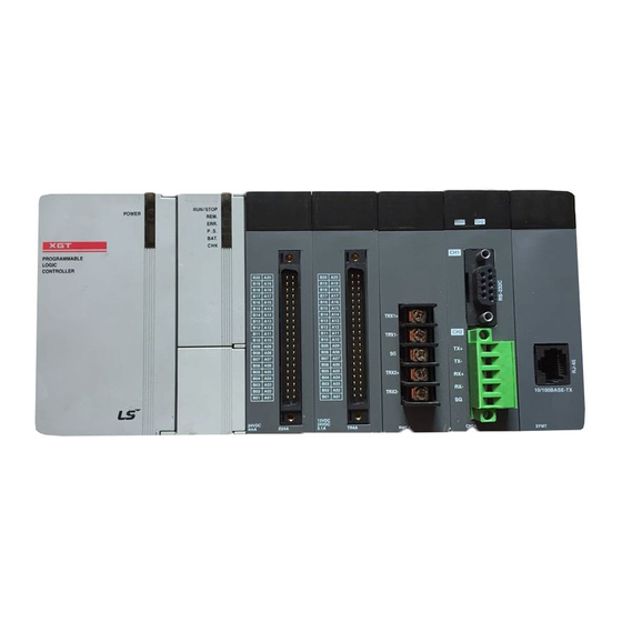
Page 24: Structure And Characteristics
Chapter 2 Product Specifications 2.3 Structure and Characteristics Names of each part of module for PLC are as follows Switch for setting station number Ethernet connector (CH 1) LOG switch Ethernet connector (CH 2) [Fig. 2.3.1] Front part of I/F module for PLC <LED name and details>... - Page 25 Chapter 2 Product Specifications Names of each part of module for PC are as follows Connector/connection Switch for : TP(UTP) Display setting : Optical(LC) station no. [Fig. 2.3.2] Front part of I/F module for PC <LED name and details> Status Details Power on (Power)
-
Page 26: Cable Specifications
Chapter 2 Product Specifications 2.4 Cable Specifications 2.4.1 UTP cable UTP cable is classified into 3 types based on the following criteria. - Shield: classified into 3 (UTP, FTP, STP) - Frequency band used: classified into 7 (Cat.1~7) - Fire: classified into 4(CMX, CM, CMR, CMP) (1) Type of cables (shield) Classification Details... - Page 27 Chapter 2 Product Specifications (2) Classification based on frequency used Frequency used Transmission Classification Purpose (MHz) Speed (Mbps) Category 1 Phonetic Frequency Phone network (2-Pair) Category 2 Multi-Pair communication cable Category 3 Phone network + Computer network 1) Computer network transmission speed Category 4 2) Low-loss communication cable Category 5 and...
-
Page 28: Optical Cable
Chapter 2 Product Specifications (4) Example (CTP-LAN5) of Category 5 twisted-pair cable (UTP) Item Unit Value Ω/km Conductor resistance(Max) 93.5 MΩ· km Insulation resistance(Min) 2,500 Voltage endurance V/min AC 500 Ω(1~100MHz) Characteristic impedance 100 ± 15 10MHz dB/100m Attenuation 16MHz or less 20MHz 10MHz... -
Page 29: Chapter 3 Installation And Test Operation
Chapter 3 Installation and Test Operation Chapter 3 Installation and Test Operation 3.1 Installation Environment This product is of high reliance regardless of installation environment. However, for the sake of reliance and stability of the system, please pay attention to those precautions described below. (1) Environmental Conditions (a) To be installed on the control panel waterproof and dustproof. - Page 30 Chapter 3 Installation and Test Operation (3) Equipment of XGB module (a) Eliminate the extension cover at the upper of module. (b) Push the module and connect it in agreement with hook for fixation of four edges and hook for connection at the bottom. (c) After connection, get down the hook for fixation at the upper part and lower part and fix it completely.
- Page 31 Chapter 3 Installation and Test Operation (5) Installation of XGB module XGB PLC is having hook for DIN rail (rail width: 35mm) so that cab be installed at DIN rail. (a) In case of installing at DIN rail - Pull hook for DIN rail at the bottom of module and install it at DIN rail - Push hook to fix the module at DIN rail after installing module at DIN rail HOOK for DIN rail (b) In case of installing at panel...
- Page 32 Chapter 3 Installation and Test Operation (6) XGB module equipment location Keep the following distance between module and structure or part for well ventilation and easy detachment and attachment. 30㎜ or above 20㎜or above 30㎜or above 5㎜ or above 5㎜ or above *1 : In case height of wiring duct is less than 50 mm (except this 40mm or above) *2 : In case of equipping cable without removing near module, 20mm or above *3 : In case of connector type, 80mm or above...
- Page 33 Chapter 3 Installation and Test Operation (8) Distance with other device To avoid radiation noise or heat, keep the distance between PLC and device (connector and relay) as far as the following figure. Device installed in front of PLC: 100 ㎜ or above Device installed beside PLC: 50 ㎜...
-
Page 34: Precaution For Handling
Chapter 3 Installation and Test Operation 3.2 Precaution for Handling The system configuration with RAPIEnet I/F module shall be performed under the following precautions. (a) Don‟t let it dropped or shocked hard. (b) Don‟t remove PCB from the case. It will cause abnormal operation. (c) Don‟t let any foreign materials including wiring waste inside the top of the module when wiring. -
Page 35: Sequence From Installation To Operation
Chapter 3 Installation and Test Operation 3.3 Sequence from installation to operation The sequence of the product from installation to operation will be described below. After the product installation is complete, install and configure the system to be operated as specified in the following sequence. 3.3.1 RAPIEnet I/F Module for PLC Begin Check the functions and specification to... -
Page 36: Rapienet I/F Module For Pc
Chapter 3 Installation and Test Operation 3.3.2 RAPIEnet I/F module for PC Begin Install I/F card for PC in an empty PCI slot. → The slot should be free from interference from other PC cards. Set the station No. of the I/F card for PC. →... -
Page 37: Parameter Setting In The Xg-Pd
Chapter 3 Installation and Test Operation 3.4 Parameter setting in the XG-PD Contents of parameter setting in XG-PD are as follows. 3.4.1 Parameter setting (1) P2P parameter Setting Lower Parameter Setting item Details menu ○ Comm. Base Module position Module ○... -
Page 38: I/O Allocation And Device Information
Chapter 3 Installation and Test Operation 3.5 I/O Allocation and Device Information 3.5.1 I/O allocation (1) Using XGK CPU (a) Configuration method of basic system The features of Basic system consisted by connecting the main base and expanded base by a cable are as follows. The number of steges of expanded base is limited according to the CPU type and the allocation method of I/O No. - Page 39 Chapter 3 Installation and Test Operation (d) Maximum configuration 1) Max. configuration of basic system (point fixed) Slot no.: P0040 P0080 P0120 P0160 P0200 P0240 P0280 P0000 System Configuration Main base Power Example 1 (base no.:0) P003F P007F P011F P015F P019F P023F P027F...
- Page 40 Chapter 3 Installation and Test Operation 2) Max. configuration of basic system (point variable) Slot no.: P0000 P0010 P0020 P0030 P0040 P0050 P0060 P0070 System Main base Power Configuration (base no.:0) P000F P001F P002F P003F P004F P005F P006F P007F Example 2 Expanded cable Slot no.: - I/O point variable...
- Page 41 Chapter 3 Installation and Test Operation (2) Using XGI CPU (a) Basic system configuration Classification XGI-CPUU Max. extension stage 7 stages Max. number of I/O module extension 96 moduls mounted 16 points module : 1,536 points Max. I/O contact ...
- Page 42 Chapter 3 Installation and Test Operation (b) Max. system configuration Slot no.: 0.0.0 0.1.0 0.2.0 0.3.0 0.4.0 0.5.0 0.6.0 0.7.0 Basic base System Configuration Power Example 2 (Base no.:0) 0.0.16 0.1.15 0.2.15 0.3.15 0.4.15 0.5.15 0.6.15 0.7.15 - XGI-CPUU - 8 slot base Expanded cable Slot no.: - When installing...
-
Page 43: Installation
Chapter 3 Installation and Test Operation 3.6 Installation 3.6.1 Installation of XGL-EIMT and XOL-EIMT Twisted pair cable 8 pin RJ45 plug [Fig. 3.6.1] 100BASE-TX Installation The max. segment length of 100BASE-TX is 1000 m (distance from module to module). Use Straight cable or Cross cable. Straight cable between Pin No. - Page 44 Chapter 3 Installation and Test Operation (1) UTP installation (a) In order to transmit reliable 100Mbps sign with UTP cable, characteristics of patch cord, line cord, patch panel and DVO (Data Voice Outlet) shall conform to the Category 5 Spec. (EIA/TIA-568A). (b) Be careful not to allow the length of patch cord to exceed 7m in cross-connect system.
-
Page 45: Installation Of Xgl-Eimf And Xol-Eimf
Chapter 3 Installation and Test Operation 3.6.2 Installation of XGL-EIMF and XOL-EIMF Multi mode LC type [Fig. 3.6.2] 100BASE-FX Installation The max. segment length of XGL-EIMF is 2000 m (distance from this module to the module). Let the module‟s Tx cross- connected with the other module‟s Rx, and the module‟s Rx with the other module‟s Tx. -
Page 46: Installation Of Xgl-Eimh
Chapter 3 Installation and Test Operation 3.6.3 Installation of XGL-EIMH Twisted pair cable 8 pin RJ45 Plug [Fig. 3.6.3] 100BASE-TX/100BASE-FX installation 3-18... -
Page 47: Test Operation
Chapter 3 Installation and Test Operation 3.7 Test Operation 3.7.1 Precautions for system configuration a) HS link station No. of all stations shall be different from each other including this module in order to use HS link service. b) Use the communication cable as specified only. If not, serious error may occur to communication. c) Check communication cable if disconnected or shorted prior to installation. -
Page 48: Chapter 4 System Configuration
Applicable system configuration is described below. 4.1 Available System Configuration 4.1.1 Ring type system with electric module XOL-EIMT 100Mbps Ethernet TP XGL-EIMT XGL-EIMT Total Max. 64 stations Max 64 Node XGT Series PLC System [Fig. 4.1.1] System configured by electric module... - Page 49 Chapter 4 System Configuration XOL-EIMT XBL-EIMT XBL-EIMT Max. 64 stations [Fig. 4.1.2] System configured by XBL-EIMT...
-
Page 50: Ring Type System With Optical Module
Chapter 4 System Configuration 4.1.2 Ring type system with optical module XOL-EIMF 100Mbps Ethernet Fiber Optic Cable XGL-EIMF XGL-EIMF Total Max. 64 stations Max 64 Node XGT Series PLC System [Fig. 4.1.3] System configured with optical module... -
Page 51: Ring Type System With Combined Module
Chapter 4 System Configuration 4.1.3 Ring type system with combined module XOL-EIMT 100Mbps Ethernet TP XGL-EIMT XGL-EIMH Total Maximum 64 stations Max 64 Node XGT Series PLC System XGL-EIMH XGL-EIMF 100Mbps Ethernet Fiber Optic Cable XOL-EIMF [Fig. 4.1.4] System configured combined module... -
Page 52: Line Type System With Optical Module
Total Maximum 64 stations Max 64 Node XGT Series PLC System 100Mbps Ethernet (Fiber Optic Cable, or TP) [Fig. 4.1.5] Line type system configured optical module Electric module and combined module also can be used to configure line type system. -
Page 53: Chapter 5 Communication Parameters
Chapter 5. Communication Parameters Chapter 5 Communication Parameters 5.1 Introduction The communication parameters can be classified into high speed link setting parameters and P2P setting parameters. 5.1.1 High-speed link setting parameters The high speed link is a communication method between the XGT PLC communication modules, which is used exchange data or information at preset period. -
Page 54: P2P Setting Parameters
Chapter 5. Communication Parameters 5.1.2 P2P Setting Parameters While high speed link is a periodical communication, the P2P communication is a services used to communicate with correspondent station when specific events occur. P2P can be used to transmit error information of a certain station to correspondent station, or for the communications requested by specific contact point input. -
Page 55: Comparison Between High Speed Link And P2P
Chapter 5. Communication Parameters 5.1.3 Comparison between high speed link and P2P The Table 5.1.3 compares the differences between high speed link and P2P services. The major difference is that the high speed link is for periodical communication of certain data with the correspondent station, and the P2P is for the transmission of data necessary for specific events. -
Page 56: Installation And Execution Of Software
Chapter 5. Communication Parameters 5.2 Installation and Execution of Software In order to user the XG-PD software, you need to install the XG5000. The system specifications required for the execution are as follows. (1) Personal Computer and Memory - A set of computer with Pentium and higher CPU and 128MB and more memory. (2) COM Port - RS-232C serial port or USB port is necessary. - Page 57 Chapter 5. Communication Parameters (3) Click [Next] button, and it shows License Agreement message. (4) Read carefully and press [Yes] (5) Enter your name and company name and then click [Next] button. (6) Select a folder to install XG5000 into. If you want to change the folder, click Browse… button and make or select a new folder.
- Page 58 Chapter 5. Communication Parameters (8) Check installation folder and click [Next] button. (9) Installation will be started as shown below. (10) Wait a second for the installation to be complete.
-
Page 59: Installation Of Usb Device Driver
Chapter 5. Communication Parameters 5.2.2 Installation of USB device driver If XG5000 is installed on Windows XP for the first time, It needs USB device driver installation as an additional step. USB device driver shall be also installed as described below. If your OS is Windows 2000, XG5000 will be installed with USB device driver automatically. - Page 60 Chapter 5. Communication Parameters (4) Among driver searching options, select “Search for the best driver in these locations” and check “Include this location in the search”. (5) Click [Browse] button. On Browse Folder Dialog Box, select Drivers‟ folder where XG5000 is installed.
- Page 61 Chapter 5. Communication Parameters (6) Click [OK] button. Then, a computer starts searching for the driver files in the selected folder. (7) If the computer found the most suitable device driver, you will be asked to decide to install the selected device driver. Since USB device driver operated stably based on Windows OS, you may click [Continue Anyway] button.
- Page 62 Chapter 5. Communication Parameters (8) If the device driver has been installed completely, the Installation Complete Dialog Box will be displayed as follows. Click [Finish] button to end the installation of the driver. 5-10...
-
Page 63: Confirmation Of Installed Usb Device Drive
(a) Normal case The USB device driver for XGT PLC has been installed successfully, if the list [LSIS XG Series] appears with the figure under [Universal Serial Bus Controller]. 5-11... - Page 64 Chapter 5. Communication Parameters (b) Abnormal case The device driver has not been installed successfully, if the following figure is displayed. If the USB driver for XGT PLC is not installed successfully, reinstall the USB driver for XGT PLC in the following steps. [Steps] (1) On the device driver with the icon with an exclamation mark, click the right button of the mouse.
- Page 65 Chapter 5. Communication Parameters (2) H/W Update Wizard Dialog Box will appear. Select the option “Installation from a list or specific location (Advanced)” and click [Next]. The next sequence is manually the same as in Installation of Device Driver. If the USB driver for XGT PLC is not installed successfully, reinstall the USB driver for XGT PLC in the following steps [Steps] (1) If the device driver has been installed incorrectly or in error, execute H/W Update Wizard.
- Page 66 Chapter 5. Communication Parameters (2) On search and installation options, select [Don‟t Search. I will choose the driver to install.] and click [Next] (3) Click [Have Disk…] on the Dialog Box below 5-14...
- Page 67 Chapter 5. Communication Parameters (4) If Installation Dialog Box is displayed on the disk, click [Browse] button. (5) From the Browse File Dialog Box, move to the folder XG5000 is installed in. Select drivers folder to display GmUSBD.inf file. With this file selected, click [Open] button. (6) On the item of „Copy manufacturer‟s files from‟, a directory with the file of the device driver will be displayed.
- Page 68 Chapter 5. Communication Parameters (7) On „Show compatible hardware‟ list of the device driver Select Dialog Box, select “LSIS XGSeries” driver and then click [Next] button (8) Hardware Installation Dialog Box will appear. Click [Continue Anyway] to go on with the installation...
- Page 69 Chapter 5. Communication Parameters (9) Completing the Hardware Update Dialog Box will appear. Click [Finish] button to end the installation of the driver 5-17...
-
Page 70: Registration Of Communication Module
Chapter 5. Communication Parameters 5.3 Registration of Communication Module In order to use RAPIEnet I/F module, communication parameters shall be specified in XG-PD. And for system setting of Cnet I/F module positioned at an optional place, its applicable module shall be registered in XG-PD. How to register the optionally positioned RAPIEnet I/F module depends on On/Off line status as described below. -
Page 71: On-Line Registration
Chapter 5. Communication Parameters 5.3.2 On-line registration Step (1), (2) of off-line registration is same and the next step is as follows. (1) Input the project name, file location and PLC type the user is using. (2) If connection fails, check the connection status. Select [Online] – [Connection settings] or click the icon ( ). -
Page 72: How To Read The Parameter Saved In The Plc
Chapter 5. Communication Parameters 5.3.3 How to read the parameter saved in the PLC To read the parameter saved in the PLC, follow the below sequence. (1) Select the „Open from PLC‟. (2) After setting the connection type and depth, click the connection. (3) Input the project name and file location and click the OK. -
Page 73: Module Setting Method
Chapter 5. Communication Parameters 5.3.4 Module setting method To use RAPIEnet I/F module., set as the following steps (1) Direct input in project window [Online] – [Project Window], Double-clicks the slot number which is mounted REPIE net I/F module. Communication module setting window is appeared on the main window. (2) Read I/O Information Read the IO information of the currently mounted modules by [Online]-[Read IO Information] after connection. -
Page 74: Menu Bar And Shortcut Of Xg-Pd
Chapter 5. Communication Parameters 5.3.5 Menu bar and shortcut of XG-PD The following is menu bar and short cut of XG-PD. Menu bar Menu Icon Contents New File Makes new file Open... Opens the saved file Open from PLC Opens the file saved in the PLC Save Saves the current file File... -
Page 75: How To Set The Parameter According To Service
Chapter 5. Communication Parameters 5.4 How to set the parameter according to service 5.4.1 High-speed link service HS link as a communication method between XGT PLC communication modules is used to exchange data or information with correspondent station periodically for a specific time, through which the changed data of self station or the correspondent station can be referred to for each other periodically for efficient application to the operation system and execution of communication only with simple parameters setting. - Page 76 Chapter 5. Communication Parameters (2) Block setting … (a) Mode: transmission/reception (b) Station No.: set up correspondent station No. for receiving only (c) Block No. This parameter is for communicating large volume of data in multiple areas of a station, by classifying the data in multiple blocks.
- Page 77 Chapter 5. Communication Parameters (4) Read high speed parameter Select „Read Parameter‟ from the Online menu. Check the desired parameter and click Confirm button to read the high speed link parameter. (5) High speed link information The high speed link information is provided to the XG5000 user as user keyword for use in programming. Type of high speed link flags 5-25...
-
Page 78: P2P Service
Chapter 5. Communication Parameters 5.4.2 P2P Service P2P service acts as the client of the communication module. This service can be used by setting the XG-PD parameters. Up to 8 P2P parameters can be set up. Each P2P parameter consists with maximum 64 P2P blocks. Major functionalities of the P2P service are listed below. -
Page 79: Operation Start-Up
Chapter 5. Communication Parameters 5.5 Operation Start-up RAPIEent I/F module‟s operation is divided into P2P service and High-speed link service generally. When setting the RAPIEnet I/F module as server, follow the 6.3 and when setting the RAPIEnet I/F module as P2P service, follow the Chapter 7 about parameter setting 5.5.1 XG-PD setting (1) Overview... -
Page 80: When Operating In High Speed Link Service
Chapter 5. Communication Parameters [Fig. 5.5.1] XG-PD basic window 5.5.2 When operating in high speed link service (1) Parameter setting Following window will appear when the high speed link parameter is selected. 5-28... - Page 81 Chapter 5. Communication Parameters (a) Communication module setting (double-click the „High-speed Link 1) Classification Description Module type Select PLC2PLC. Communication Base Number Select the No. of the base of the installation. module settings Slot number Select the No. of the slot of the installation. Communication Period type Set the data transmission period.
- Page 82 Chapter 5. Communication Parameters (2) Window for setting high speed link parameters The meanings of the parameters are as follow Classification Description Send Transmit data Mode Receive Receive data Station Partner station The No. of the partner module for the reception number number Block number...
- Page 83 Chapter 5. Communication Parameters (4) Read high speed link parameter First, connect with the CPU. After the connection, select „Read Parameter‟ in the online. The window shown in [Fig. 5.5.2] will appear. Select desired parameter and click Confirm button to read the high speed link parameter setting. [Fig.
- Page 84 Chapter 5. Communication Parameters * Enable Link through flag It describes “Enable Link” method through flag. The following XG5000 version, CPU OS version is needed. Item Version XG5000 V3.61 or above XGR CPU V1.91 or above XGI CPU V3.4 or above XGK CPU V3.7 or above Flag list related with “Enable Link”...
- Page 85 Chapter 5. Communication Parameters Flag Data type Device Description _HS10_REQ F10309 HS link 10 enable/disable request _HS11_REQ F1030A HS link 11 enable/disable request _HS12_REQ F1030B HS link 12 enable/disable request _HS1_REQ_NUM F10310 HS link 1 enable/disable setting _HS2_REQ_NUM F10311 HS link 2 enable/disable setting _HS3_REQ_NUM F10312 HS link 3 enable/disable setting...
-
Page 86: Operating In P2P Service
Chapter 5. Communication Parameters 5.5.3 Operating in P2P service (1) Parameter setting Following window will appear when P2P Parameter is selected. (a) Communication module setting In the P2P window, click the P2P01 to register the module currently in the slot.. The function of each setting is as follows. - Page 87 Chapter 5. Communication Parameters When the communication module has been set up, P2P block will appear in the P2P window. Click this will show following window where P2P blocks can be set up. (b) Setting parameter blocks Classification Description P2P function Select whether to transmit or receive.
- Page 88 Chapter 5. Communication Parameters (d) Enable Link e 1) Select „Online → Link Enable‟ or click ( ) icon. 2) Select the P2P which is set up, and click „Write.‟ (e) Operation check 1) Select „Onloine → System Diagnosis‟ or click ( ) icon.
-
Page 89: Chapter 6 High-Speed Link
Chapter 6 High-speed Link Chapter 6 High-speed Link 6.1 Introduction High-speed link (HS Link) is a communication method between XGT PLC communication modules to send and receive data with HS link parameters setting, which can also allow the user to use XG-PD to exchange data with parameters setting of Tx/Rx data size, Tx/Rx period, Tx/Rx area and area to save through its data transmission service function. -
Page 90: Hs Link Tx/Rx Data Processing
Chapter 6 High-speed Link 6.2 HS link Tx/Rx Data Processing HS link application will be described below with the example where FDEnet I/F modules of the stations No.0 and No.1 are to send and receive the data between each other. Its setting sequence is as follows;... -
Page 91: Operation Sequence Through High-Speed Link
Chapter 6 High-speed Link 6.3 Operation Sequence through High-speed Link <Select high speed link >. High speedlink window: open the high speed link setting window of XG-PD <Seelct high speed link parameters >. High speed link 1~12: set up according to the No.of the communication modules in use (select high speedlink 1 whenusing 1 communication module * For XGB, only High speed link 1~2 are supported <High speed link setting (link setting)>. -
Page 92: Hs Link Parameters Setting
Chapter 6 High-speed Link 6.4 HS link parameters setting HS link parameters can be specified as selected on the XG-PD‟s HS link screen for applicable items, whose setting sequence and respective functions are as follows. 6.4.1 HS link parameters setting of XG-PD (1) Execution of XG-PD If XG-PD is executed for the first time, the screen will be displayed as shown in [Fig. - Page 93 Chapter 6 High-speed Link (3) High-speed link parameter setting (a) Initial screen setting of High-speed link parameter Select XG-PD‟s HS link window as shown on [Fig. 6.4.3]. [Fig. 6.4.3] Initial setting screen of High-speed link (b) Setting of communication module and communication period Double-click one of the HS links 01~12 on the [Fig.
- Page 94 Chapter 6 High-speed Link Item Details Specify the communication module installed. (RAPIEnet) Module type Specify the base position the module is installed on (max. 7 stages can be added). Communication Base no. : 0 ~ 7 Setting range module setting Specify the slot position the module is installed on (max.
- Page 95 Chapter 6 High-speed Link (d) Setting of High-speed link blocks Double-click „Block‟ on [Fig.6.4.5] to open [Fig.6.4.6]. [Fig. 6.4.6] Setting screen of HS link blocks Classification Details Send Send data Mode Receive Receive data Partner station Settable in case of Receive mode Station number number Range: 0 ~ 63...
- Page 96 Chapter 6 High-speed Link (4) How to download High-speed link parameters Click “Online” “Write Parameter” in XG-PD, check the applicable HS link and then click [OK]. [Fig. 6.4.7] Write Parameter Screen (5) High-speed link parameter setting Click “Online” “Enable Link” in XG-PD, check the applicable HS link and then click [Write]. If HS link is enabled, on the module‟s LED display HS LED will be On, when HS link starts.
-
Page 97: High-Speed Link Information
Chapter 6 High-speed Link 6.5 High-speed link information 6.5.1 High-speed link flag With HS link service used to exchange data between communication modules of two or more stations, it provides a checking method of HS link service status for the user through HS link information so to confirm reliability of the data read from the correspondent station via the HS link. - Page 98 Chapter 6 High-speed Link (1) Run-link ( _HSxRLINK, x=HS link no. (1~12) ) As the whole information it shows whether HS link is normally executed through the user defined parameters, whose contact will be kept „On‟ if once „On‟ until Link Enable is „Off‟, and also will be „On‟ under the conditions specified below. ①...
-
Page 99: Monitor Of High-Speed Link Information
Chapter 6 High-speed Link 6.5.2 Monitor of High-speed link information HS link information can be checked through the variable monitor on the monitor menu after XG5000 is on-line connected, or through the XG-PD diagnosis service. (1) Variable Monitor Variable monitor is a function used to select an item only necessary to monitor by means of XG5000‟s flag monitor function. Select [View] [Variable Monitor Window] to display the variable register screen as shown on [Fig. - Page 100 Chapter 6 High-speed Link (b) To monitor the high speed link of another PLC2PLC module on the network, select XG-PD → „Access‟ → „Online‟ → „System Diagnosis,‟ place the mouse pointer on the XGL-EIMT. Right-click the mouse button, select „Autoscan.‟ A screen shown in [Fig.
-
Page 101: Chapter 7 P2P Service
Chapter 7 P2P Service Chapter 7 P2P Service 7.1 Introduction This service is used to write the self-station‟s data on a specific area of the correspondent station, or to read the data from a area of the correspondent station. Type and application of P2P provided for users will be described. Programming sequence with P2P used is as follows;... -
Page 102: P2P Application
Chapter 7 P2P Service 7.3 P2P Application In order to execute P2P service, register communication modules on the XG-PD‟s P2P register window, where up to 64 P2P blocks can be set. [Fig. 7.3.1] P2P parameters screen First, register the communication modules to execute P2P service so to set P2P blocks on the empty P2P register window as above. - Page 103 Chapter 7 P2P Service Register type, base and slot positions in [Fig. 7.3.2] and click [OK] to display the screen as shown in [Fig. 7.3.3]. [Fig. 7.3.3] P2P parameters screen Double-click P2P block in [Fig. 7.3.3] to display the „P2P block setting‟ screen as shown in [Fig. 7.3.4]. [Fig.
-
Page 104: Functions And Setting Of P2P
Chapter 7 P2P Service 7.3.1. Functions and setting of P2P On the [Fig. 7.3.4] P2P block setting screen, double-click the P2P function screen as shown below in [Fig. 7.3.5]. [Fig. 7.3.5] P2P function screen (1) READ It is used to read the specified area of the correspondent station to save on the specified area of the self-station when the defined event happens. - Page 105 Chapter 7 P2P Service - Variable setting: in the P2P block setting window, click Setting. The Variable Setting window will appear, as shown in [Fig. 7.3.7]. (2) WRITE It is used to write the data of the self-station on an optional area of the correspondent station when the defined event happens.
-
Page 106: Operation Sequence Of P2P Service
Chapter 7 P2P Service 7.4 Operation Sequence of P2P Service After P2P setting is complete, download the P2P parameters and start the P2P service to make the service available. (1) P2P parameters download In order to download the P2P parameters after registered, first connect XG-PD to CPU. Select [Online] - [Write Parameter] to arrange and display the P2P parameters registered among P2P parameters 0~7 as shown below;... -
Page 107: P2P Service Information
Chapter 7 P2P Service 7.5 P2P Service Information P2P service information provides P2P related data through XG-PD. 7.5.1 P2P service from the XG-PD system diagnosis (a) Select XG-PD „Connect‟ „Online‟ „System Diagnosis‟. [Fig. 7.5.1] System Diagnosis (b) With the mouse cursor placed on XGL-EIMH, click the right mouse button and select „Status by service‟ to open [Fig. -
Page 108: Chapter 8 Remote Connection Service
Chapter 8 Remote Connection Service Chapter 8 Remote Connection Service 8.1 Introduction This function is used for programming, downloading of user program, program debugging, monitoring, etc in network system where PLCs are connected with each other via RAPIEnet I/F module by remote control without moving the physical connection status of XG5000 or XG-PD. -
Page 109: Setting And Connection
Chapter 8 Remote Connection Service 8.2 Setting and Connection All PLCs connected via XGT network are available to connect with each other by remote connection service. XG-PD remote connection is composed of stage 1 and stage 2 connections as described below. The followings explains remote 1 and remote 2 connections. - Page 110 Chapter 8 Remote Connection Service Item Details Type Selects a connection media(RS-232C or USB) Connection 1) Local: connection of PC and CPU settings Depth 2) Remote 1: connection stage 1 via comm. module 3) Remote 2: connection stage 2 via comm. module Timeout interval Setting Timeout interval in case of connection CPU (1~9s) General...
- Page 111 Chapter 8 Remote Connection Service If you click the “Preview” at the “Online Settings” window, you can check the remote 1 connection setting [Figure 8.2.4] View Connection Settings window If setting is complete, exit from an option window and execute online connection In case of the connection failure, the following message appears.
-
Page 112: Remote 2 Connection
Chapter 8 Remote Connection Service 8.2.2 Remote 2 connection For remote 2 connection, XG5000 is connected through PLC A’s RAPIEnet PLC B’s RAPIEnet PLC C’s RAPIEnet For remote stage 2 connection, XG-PD shall be in off-line state. At this state, Select “Online-Connection Settings” and select “Remote 2” at Depth. [Figure 8.2.7] Online Settings window Click “Settings”. - Page 113 Chapter 8 Remote Connection Service Set a “Remote 2” tap [Figure 8.2.9] Details window: remote 2 Items Details Select a network type Network type For RAPIEnet I/F module, select RAPIEnet. Remote Base number Base number of the communication module at remote 1 communication Slot number Slot number of the communication module at remote 1...
- Page 114 Chapter 8 Remote Connection Service You can check your settings through “Preview” button of [Figure 8.2.7] In case you set as above, “Preview” window is as follows. [Figure 8.2.10] Preview window of remote 2 connection If setting is complete, exit from an option window and execute online connection Remote 2 connection state is same as the connection state connecting RS-232C cable to the target PLC of remote connection 2.
-
Page 115: Chapter 9 Example Program
Chapter 9 Example Program Chapter 9 Example Program 9.1 High Speed Link Program 9.1.1 High Speed Link parameter setting Describes how to set HS link parameter at XGnet I/F system RAPIEnet RAPIEnet [Fig. 9.1.1] I/O configuration and TRX data TRX structure I/O configuration TX area RX area... - Page 116 Chapter 9 Example Program Set HS link parameter for example system as shown below Select one among 12 HS link parameters at HS link setting screen like [Fig. 9.1.2] and register the module [Fig. 9.1.2] Communication module and period setting Set Module type as RAPIEnet and define Base Number abd Slot Number.
- Page 117 Chapter 9 Example Program [Fig. 9.1.4] HS link block setting of XGT station no.2 [Fig. 9.1.5] HS link block setting of XGT station no.3 In case HS link is under operation, if user download HS link parameter, Enable Link is canceled automatically and it is set after download.
-
Page 118: How To Set Hs Link Speed
Chapter 9 Example Program (3) Enable Link Select „Online‟ „Enable Link‟ and check relevant HS link and click „Write‟ button [Fig. 9.1.7] is screen of „Enable Link‟ [Fig. 9.1.7] screen of Enable Link: HS link Write parameters about XGT system station no.1,2,3 9.1.2 How to set HS link speed Above example is simple system where each 3 stations sends/receives 2 word data. -
Page 119: High Speed Link Diagnosis Service
Chapter 9 Example Program 9.1.3 High Speed Link Diagnosis service To check if system is normal, at „System Diagnosis‟, click XGnet I/F module with right button of mouse and select „Status by Service‟ and open „HS Link service‟ tap. [Fig. 9.1.8] Screen of „Status by Service‟: HS link service... -
Page 120: P2P Program
Chapter 9 Example Program 9.2 P2P Program 9.2.1 P2P parameter setting At XGT XGnet I/F system configured as figure below, station 1 is master. Here describes how to set P2P parameter for data communication as the following I/O structure. But, We will assume that all stations are normal. RAPIEnet RAPIEnet RAPIEnet... - Page 121 Chapter 9 Example Program (4) Register P2P parameter defined at P2P block setting window. (a) 1: When bit 2 of FW9 is set, read %MW10, 20, 30 of partner 2 and save them at %MW0, 1, 2 of self station [Fig.
- Page 122 Chapter 9 Example Program (c) 3: When bit 0 of MW5 is set, read %MW0, 1, 2 of self station and save them at %MW10, 20, 30 of partner 4 [Fig. 9.2.7] P2P block setting: 3 [Fig. 9.2.8] P2P variable setting: 3 (d) 4: When bit3 of MW6 is set, read 10 words from %MW10 and save them %MW100 of partner 5 [Fig.
- Page 123 Chapter 9 Example Program (5) Download P2P parameter Select “Online – Write Parameter” of XG-PD and download P2P parameter to start service among the registered P2P parameter [Fig. 9.2.10] Screen of Wirte Parameter: P2P The downloaded P2P parameter is backed up regardless of power (6) Enable P2P link Though P2P parameter is downloaded normally, P2P service doesn‟t start.
-
Page 124: P2P Diagnosis
Chapter 9 Example Program 9.2.2 P2P Diagnosis To check if system is normal, at „System Diagnosis‟, click XGnet I/F module with right button of mouse and select „Status by Service‟ and open „P2P service‟ tap. [Fig. 9.1.8] Screen of status by service: P2P service 9-10... -
Page 125: Chapter 10 Diagnostic Function
Chapter 10 Diagnostic Function Chapter 10 Diagnostic Function This chapter describes the methods of investigating the statuses of the system, Modules, and network, and downloading OS. The system configuration and the status of RAPIEnet I/F Module can be checked with following procedures. The downloading method of RAPIEnet I/F Module OSis provided in this chapter. -
Page 126: Communication Module Information
Chapter 10 Diagnostic Function 10.2 Communication Module information This shows the basic information on the RAPIEnet I/F MODULE. In the system diagnosis window, click the RAPIEnet I/F MODULE whose communication module information you want to view, and select „Communication Module Information.‟ The Communication Module Information window appears as shown in [Fig. -
Page 127: Auto Scan
Chapter 10 Diagnostic Function 10.3 Auto Scan This function checks the configuration and module status of the network system constructed with RAPIEnet I/F MODULE and measure cable distance. 10.3.1 Auto scan You can check the network system configuration of the entire system. In the system diagnosis window, right-click the RAPIEnet I/F MODULE for which the auto scan is to be conducted, select „Auto Scan.‟... -
Page 128: Cable Distance Measurement
Chapter 10 Diagnostic Function 10.3.2 Cable distance measurement Throughout the entire network system, cable distance between the RAPIEnet I/F Modules can be measured. Select the „Measure Cable Distance‟ on top of the Auto Scan window to look up the cable distance and the date of measurement, as shown in [Fig. - Page 129 Chapter 10 Diagnostic Function [Fig. 10.3.3] Remote diagnostic service menu window (1) Remote communication module information In the menu of [Fig. 10.3.3], select „Communication Module Information.‟ The remote communication module information window will appear as shown in [Fig. 10.3.4]. [Fig. 10.3.4] Remote communication module information window For the details of the communication module information items in [Fig.
- Page 130 Chapter 10 Diagnostic Function [Fig. 10.3.5] Remote Service Status window: P2P service [Fig. 10.3.6] Remote Service Status window: high speed link service 10-6...
- Page 131 Chapter 10 Diagnostic Function For the details of the [Fig. 10.3.5] Service Status: P2P Service items, see Chapter 7. P2P Service, and for the details of [Fig. 10.3.6] Service Status: high speed link service items, see Chapter 6. High Speed Link Service. (3) Remote media information Select “Media Information from the menu tree in [Fig.
-
Page 132: Media Information Diagnosis
Chapter 10 Diagnostic Function 10.4 Media information diagnosis This function checks the network media information of the RAPIEnet I/F Module. 10.4.1 Media information The status of the service or media of the RAPIEnet I/F Modules can be checked with the number of packets. In the system diagnosis window, right-click the RAPIEnet I/F Module whose media status is to be checked, and select Media Information. -
Page 133: View Error Details
Chapter 10 Diagnostic Function 10.4.2 View error details The detail information on the errors in the frames which are transmitted from or received by RAPIEnet I/F Modules can be viewed. In the contents of the packet monitoring in the media information window, if the error count is 1 or more, the View Error Detail button on the bottom window is activated. -
Page 134: Troubleshooting
Chapter 10 Diagnostic Function 10.5 Troubleshooting This chapter is to describe defects and errors that may occur in system operation, their causes and actions to take against. If any error occurs on FDEnet I/F Module, its related details can be checked through the procedures below. Surely follow the troubleshooting procedures in the sequence as specified to check for abnormal Module state. -
Page 135: Diagnosis Of Communication Module Through Xg5000
Chapter 10 Diagnostic Function 10.5.2 Diagnosis of Communication Module through XG5000 XG5000 program can be used to monitor the communication Module simply to check for any error thereon. Connect RS- 232C connector with CPU port and then select [Online] [PLC History] -> [PLC Errors/Warnings] in XG5000. [Fig. - Page 136 Chapter 10 Diagnostic Function [Fig. 10.5.3] Memory area log of System Log Time and description of the events such as error or service provision can be viewed. (2) Flash area log When error or service provision cannot be checked with XG-PD, or to save the content of the current memory area in flash, press the log switch on the front of the RAPIEnet I/F Module.
-
Page 137: Appendix
Appendix Appendix A.1 Terminology 1. IEEE 802.3 IEEE 802.3 specifies standards for CSMA/CD based Ethernet. Exactly it is a LAN based on CSMA/CD (Carrier Sense Multiple Access with Collision Detection) Ethernet designed by IEEE 802.3 group, which is classified into detailed projects as specified below;... - Page 138 Appendix 10. Packet A package of data which is the basic unit used to send through the network. Usually the package is made of several tens or hundreds of bytes with the header attached in front to which its destination and other necessary information are added 11.
-
Page 139: List Of Flags
Appendix A.2 List of Flags A.2.1 List of Special Relays (F) Device 1 Device 2 Type Variable Function Description F0000 DWORD _SYS_STATE Mode & Status PLC mode & run status displayed. RUN status. F00000 _RUN F00001 _STOP STOP STOP status. F00002 _ERROR ERROR... - Page 140 Appendix Device 1 Device 2 Type Variable Function Description Compile code 1 Compile code 1 selected. F0001E _CB1 F0001F _CB2 Compile code 2 Compile code 2 selected. System error Serious error in system reported. F0002 DWORD _CNF_ER CPU error CPU configuration error found. F00020 _CPU_ER Module type error...
- Page 141 Appendix Device 1 Device 2 Type Variable Function Description HS link – parameter 5 error HS link 5 F0004C _HS_WAR5 HS link – parameter 6 error HS link 6 F0004D _HS_WAR6 HS link – parameter 7 error HS link 7 F0004E _HS_WAR7 HS link –...
- Page 142 Appendix Device 1 Device 2 Type Variable Function Description Repeat specific scan ON/OFF CLOCK 2 for specific scan F00102 _USR_CLK2 Repeat specific scan ON/OFF CLOCK 3 for specific scan F00103 _USR_CLK3 Repeat specific scan ON/OFF CLOCK 4 for specific scan F00104 _USR_CLK4 Repeat specific scan...
- Page 143 Appendix Device 1 Device 2 Type Variable Function Description PUT/GET complete 6 Added base step 6 PUT / GET complete F0029 WORD _PUTGET_NDR6 PUT/GET complete 7 Added base step 7 PUT / GET complete F0030 WORD _PUTGET_NDR7 CPU type Information on CPU type displayed. F0044 WORD _CPU_TYPE...
- Page 144 Appendix Device 1 Device 2 Type Variable Function Description Increased if module’s block data serviced Block service F0074 DWORD _CA_CNT Increased if module’s block data service Block service LIMIT F0076 DWORD _CA_LIM_CNT abnormal. Increased if module’s block data service Block service F0078 DWORD _CA_ERR_CNT ERROR...
- Page 145 Appendix Device 1 Device 2 Type Variable Function Description F0116 WORD _FUSE_ER4 Fuse blown 4 error Added base step 4 Fuse blown error F0117 WORD _FUSE_ER5 Fuse blown 5 error Added base step 5 Fuse blown error F0118 WORD _FUSE_ER6 Fuse blown 6 error Added base step 6 Fuse blown error F0119...
- Page 146 Appendix Device 1 Device 2 Type Variable Function Description F0148 DWORD _LOG_ROTATE Log rotate Log rotate information saved. F0150 WORD _BASE_INFO0 Slot information 0 Main base slot information WORD _BASE_INFO1 Slot information 1 Added base step 1 slot information F0151 F0152 WORD _BASE_INFO2...
-
Page 147: List Of Communication Relays (L
Appendix A.2.2 List of Communication Relays (L) - Special register for data * HS link No. 1 Keyword Type Detail Description Displays all stations normally operated as specified in HS link parameter, which will be On if 1.There is no error with all stations specified in parameter in RUN mode HS link parameter 2. - Page 148 Appendix K as a block number is displayed through 8 words by 16 for 1 word for the information of 128 blocks from 000 to 127. For example, block information of 16~31, 32~47, 48~63, 64~79, 80~95, 96~111, 112~127 will be displayed in L00011, L00012, L00013, L00014, L00015, L00016, L00017 from block 0 to block 15 for mode information (_HS1MOD).
- Page 149 Appendix P2P parameters: 1~8, P2P block: 0~63 Keyword Type Detail Description P2P parameter No.1, block No.00 P2P parameter No.1, block No.0 service complete L006250 _P2P1_NDR00 service complete normally normally P2P parameter No.1, block No.00 P2P parameter No.1, block No.0 service complete L006251 _P2P1_ERR00 service complete abnormally...
-
Page 150: List Of Link Device (N
Appendix A.2.3 List of Link device (N) - Device saving the size and contents about P2P number and block number - P2P No.: 1 ~ 8, P2P block: 0 ~ 63 Keyword Type Detail Description P2P parameter No.1, block No.00’s correspondent station No. saved P2P parameter No.1, block No.00’s N00000... - Page 151 Appendix Keyword Type Detail Description P2P parameter No.1, N00036 ~ _P1B00WD Device block No.00 saved area P2P parameter No.1, block No.00 saved area device 4 saved N00039 structure device 4 P2P parameter No.1, _P1B00WS N00040 Word block No.00 saved area P2P parameter No.1, block No.00 saved area size4 saved size 4 P2P parameter No.1, block No.01’s correspondent station No.
- Page 152 Appendix Keyword Type Detail Description P2P parameter No.1, _P1B01WS N00076 Word block No.01 saved area P2P parameter No.1, block No.01 saved area size 3 saved size 3 P2P parameter No.1, N00077 ~ _P1B01WD Device block No.01 saved area P2P parameter No.1, block No.01 saved area device 4 saved N00080 structure device 4...
-
Page 153: Dimension
Appendix A.3 Dimension Unit: mm XGL-EIMT/EIMF/EIMH A-17... - Page 154 Appendix XOL-EIMT/EIMF A-18...
- Page 155 Appendix XBL-EIMT A-19...
-
Page 156: Troubleshooting
Appendix A.4 Troubleshooting A.4.1 Hardware failure H/W failure Is the Check power supply/voltage power OK? Is the installation Check/correct installation environment OK? environment Is the comm module Install comm. module correctly installed? correctly Restart the system by power Off/On Does the same Is the operation Operation failure occur again? -
Page 157: Interface Failure
Appendix A.4.2 Interface failure Interface failure Is the power supply Check power supply/voltage Is the power supply Adjust/control the environment to meet the specifications Is the comm. module Install comm. module on the base correctly installed? correctly Comm module or CPU H/W failure. -
Page 158: Cpu And Interface Failure During Operation
Appendix A.4.3 CPU and interface failure during operation Interface failure during operation Is the CPU error type a comm. Is the CPU error type an I/O & module interface error? special module interface error? Conduct troubleshooting for the CPU Install the error module correctly Is the comm. -
Page 159: High-Speed Link Parameter Error
Appendix A.4.4 High-speed link parameter error High-speed link parameter error Replace battery. Download program and parameters Is the CPU backup battery OK? again Are the network type, slot, and Correct the link setting to match with the network type, self-station No. correctly set up? station No., or slot No. -
Page 160: High-Speed Link Operation Failure
Appendix A.4.5 High-speed link operation failure High-speed link operation failure In the link permission setting, turn the link permission Is the link permission ON? setting to ON Of the link settings, are the Correct the link setting to match with the network type, network type and slot &... -
Page 161: Performance Table
Appendix A.5 Performance Table A.5.1 High-speed link performance table When receiving maximum 200 words in 1 block of the RAPIEnet I/F Module, the maximum process time is 500 ㎲. The maximum number of the blocks and time of allowable reception considering the CPU scan time by the period of high speed link transmission are as follows;... -
Page 162: Error Code
Appendix A.6 Error Code A.6.1 P2P client error code Error code is expressed as hexadecimal 2 byte. You can check the error at the frame monitor. If you see the error frame by ASCII, you can see the error frame as follows. XG-PD 의... - Page 163 LSIS provides an 18-month warranty starting from the date of production. 2. Range of warranty For problems within the terms of the warranty, LSIS will replace the entire PLC or repair the defective parts free of charge except for the following cases.
- Page 164 2 Zhongshan Liu Road.Guangzhou.P.R China Tel : 86-20-8328-6754/Fax : 86-20-8326-6287 e-mail : chenxs@lsis.com.cn ※ LSIS constantly endeavors to improve its product so that 2011. 5 information in this manual is subject to change without notice. ⓒ LSIS Co., Ltd 2011 All Rights Reserved.
Need help?
Do you have a question about the XGT Series and is the answer not in the manual?
Questions and answers