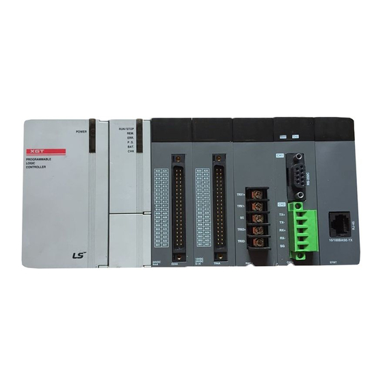
LSIS XGT Series User Manual
Positioning module ethercat, programmable logic controller
Hide thumbs
Also See for XGT Series:
- User manual (909 pages) ,
- Manual (48 pages) ,
- User manual (123 pages)
Table of Contents
Advertisement
Quick Links
Download this manual
See also:
User Manual
Advertisement
Table of Contents

Related Manuals for LSIS XGT Series


Summary of Contents for LSIS XGT Series
- Page 1 Programmable Logic Controller Positioning Module (EtherCAT) XGT Series XBF-PN08B...
- Page 2 Safety Instructions Before using the product … For your safety and effective operation, please read the safety instructions thoroughly before using the product. ► Safety Instructions should always be observed in order to prevent accident or risk with the safe and proper use the product.
- Page 3 Safety Instructions Safety Instructions for design process Warning Please install a protection circuit on the exterior of PLC so that the whole system may operate safely regardless of failures from external power or PLC. Any abnormal output or operation from PLC may cause serious problems to safety in whole system.
- Page 4 Safety Instructions Safety Instructions for design process Caution I/O signal or communication line shall be wired at least 100mm away from a high-voltage cable or power line. Fail to follow this instruction may cause malfunctions from noise Safety Instructions on installation process Caution ...
- Page 5 Safety Instructions Safety Instructions for wiring process Warning Prior to wiring works, make sure that every power is turned off. If not, electric shock or damage on the product may be caused. After wiring process is done, make sure that terminal covers are installed properly ...
- Page 6 Safety Instructions Safety Instructions for test-operation and maintenance Warning Don’t touch the terminal when powered. Electric shock or abnormal operation may occur. Prior to cleaning or tightening the terminal screws, let all the external power off including PLC power. If not, electric shock or abnormal operation may occur. ...
- Page 7 Safety Instructions Safety Instructions for waste disposal Caution Product or battery waste shall be processed as industrial waste. The waste may discharge toxic materials or explode itself.
- Page 8 Revision History Revision History Version Date Remark Revised position V 1.0 ’15. 2 First Edition © 2015 LSIS Co., Ltd. All r ights r es er ved.
- Page 9 User’s Manual. The User’s Manual describes the product. If necessary, you may refer to the following description and order accordingly. In addition, you may connect our website (http://www.lsis.co.kr/) and download the information as a PDF file. Relevant User’s Manuals No.
-
Page 10: Table Of Contents
Table of Contents ◎ Table of Contents ◎ Chapter 1 Overview………………………….......………………...……………………… 1-1 ~ 1-11 1.1 Characteristics ..............................1 - 1 1.2 Purpose of Positioning Control ........................1 - 3 1.3 Function Overview of Positioning Module ....................1 - 4 1.3.1 Positioning Control ..........................1 - 4 1.3.2 Interpolation Control ...........................1 - 5 1.3.3 Speed Control ..........................1 - 10 1.3.4 FEED Control ...........................1 - 11... - Page 11 Table of Contents 4.4 Manual Operation Parameter ........................4 - 24 4.4.1 Manual Operation Parameter......................4 - 24 4.4.2 Manual Operation Parameter Setting ....................4 - 24 4.5 Common Parameter ..........................4 - 25 4.5.1 Common Parameter ........................4 - 25 4.5.2 Common Parameter Setting ......................4 - 26 4.6 Operation Data ............................4 - 31 4.6.1 Operation Data ..........................4 - 31 4.6.2 Operation Data Setting ........................4 - 32...
- Page 12 Table of Contents 6.3.20 Speed Override (Command: XSOR) ................... 6 - 28 6.3.21 Position-specified Speed Override (Command: XPSO) .............. 6 - 29 6.3.22 Continuous Operation (Command: XNMV) ................. 6 - 30 6.3.23 Inching Operation (Command: XINCH) ..................6 - 31 6.3.24 Return to the Previous Manual Operation Position (Command: XRTP) ........
- Page 13 Table of Contents 7.3.3 Encoder Value Read (XPM_ENCRD) ....................7 - 9 7.3.4 Servo Information Read (XPM_SVERD) ..................7 -10 7.3.5 Latch Position Data Read (XPM_LRD) ................... 7 -11 7.4 Parameter/Operation Data Teaching Function Block ................7 - 12 7.4.1 Basic Parameter Teaching (XPM_SBP) ..................7 - 12 7.4.2 Extended Parameter Teaching XPM_SEP) ...................
- Page 14 Table of Contents 7.8.12 Current Position Change (XPM_PRS) ..................7 - 53 7.8.13 Encoder Value Preset (APM_EPRE) ................... 7 - 54 7.9 Error Function Blocks ..........................7 - 55 7.9.1 Error Reset (XPM_RST) ........................7 - 55 7.9.2 Error History Reset (XPM_HRST) ....................7 - 56 7.10 Other Function Blocks related with the Module ..................7 - 57 7.10.1 Floating Origin Setting (XPM_FLT) ....................
- Page 15 Table of Contents 9.1 Home Return ..............................9 - 1 9.2 Positioning Control .............................9 - 6 9.2.1 Operation Data for Positioning Control ....................9 - 7 9.2.2 Operation Mode of Positioning Control ....................9 - 8 9.2.3 Single-axis Position Control ......................9 - 23 9.2.4 Single-axis Speed Control ......................9 - 25 9.2.5 Single-axis Feed Control ........................9 - 27 9.2.6 Linear Interpolation Control with 2 axes ..................9 - 28...
- Page 16 Table of Contents 9.7.1 Teaching Array ..........................9 - 173 9.7.2 Parameter Change from Program ....................9 - 174 9.7.3 Data Change from Program ......................9 - 178 9.7.4 Write/Read Variable Data ......................9 - 180 Appendix 1 Positioning Error Information & Solutions ……………..........…… A1-1~ A1-17 Appendix 2 Module Internal Memory Address of “Read/Write Variable Data”...
-
Page 17: Characteristics
Chapter 1 Overview Chapter 1 Overview This user’s manual describes the standard of positioning module, installation method, the method to use each positioning function, programming and the wiring with external equipment. 1.1 Characteristics The characteristics of positioning module are as follows. (1) The positioning module is available for high performance CPU system of XGB Series(XBC-U, XEC-U). - Page 18 Chapter 1 Overview (6) Easy maintenance Various data such as operation data, operation parameter are saved on MRAM(Magnetic Random Access Memory) in positioning module. Therefore, data will be saved without delay time and there is no limit in writing count. (7) Self-diagnosis, monitoring and test are available with strong software package, XG-PM.
- Page 19 Chapter 1 Overview 1.2 Signal Flow of Positioning Module The flow of PLC system using the positioning module is as follows. Writing XG5000 sequence Program PLC CPU Setting for control - Operation parameter XG-PM - Operation data Encoder 1 - Cam data Positioning module - Servo parameter XBF-PN08B...
-
Page 20: Function Overview Of Positioning Module
Chapter 1 Overview 1.3 Function overview of Positioning module Describe Representative functions of positioning module (Coordinate & Linear Interpolation, Circular Interpolation & Stop) briefly. 1.3.1 Position Control Execute positioning control for the designated axis from starting position(current position) to goal position(the position to move to). -
Page 21: Interpolation Control
Chapter 1 Overview [ Example ] ■ Starting Position : 5000 ■ Goal Position : -7000 In this condition, it moves reversely and stops at -2000. -2000 5000 Reverse positioning control(movement value -7000) Goal Position Starting Positon 1.3.2 Interpolation Control (1) Linear Interpolation Control Execute Linear interpolation control with designated axis at start position (Current position). - Page 22 Chapter 1 Overview (Y axis) Starting position 4000 Y axis movement value (1000-4000=-3000) Goal 1000 Position X axis 1000 5000 10000 X axis movement value (10000-1000=9000) (b) Linear Interpolation by incremental coordinates 1) Execute linear interpolation to position including the moving direction and amount of movement with the goal for each axis from starting position.
- Page 23 Chapter 1 Overview (2) Circular Interpolation Control Execute interpolation operation along the trace of circle with 2 axes in forward direction that already designated for each axis. Circular interpolation has 3 types according to auxiliary point, Middle point method passing auxiliary point, Center point method using auxiliary point as center of circle and Radius method using auxiliary point as radius of circle.
- Page 24 Chapter 1 Overview (b) Center Point Specified Circular interpolation 1) Starts operating from starting position and execute circular interpolation along trace of circle that has distance from starting point to designated center point as radius. Forward Direction Goal Operating by circular interpolation Position Starting position...
- Page 25 Chapter 1 Overview (c) Radius Specified Circular interpolation 1) Starts operating from starting position and execute circular interpolation along trace of circular arc that has value designated in auxiliary point of main axis as it radius. Depending on size setting of circular arc(<180°,>=180°), center point of circular arc will be different.
-
Page 26: Speed Control
Chapter 1 Overview 1.3.3 Speed Control (1) It is executed by positioning operation start command (Direct start, Indirect start, Synchronous start) and keeps operating with designated speed until Dec. stop command. (2) Speed control has forward operation and reverse operation. (a) Forward operation : Position value >= 0 (b) Reverse operation : Position value <... -
Page 27: Feed Control
Chapter 1 Overview 1.3.4 FEED Control (1) After executed by positioning start, resets the current position as 0 and starts positioning as much as movement value already set. (2) Movement direction is decided by movement value. (3) Feed control has forward direction operation and reverse direction operation. (a) Forward direction : Position value >= 0 (b) Reverse direction : Position value <0 (4) Operation timing is as follows. -
Page 28: General Specification
Chapter 2 Specifications Chapter 2 Specifications 2.1 General Specifications The following table shows the general specification of XGT series. Related Item Specifications specifications Ambient ℃∼+55℃ temperature Storage ℃∼+70℃ temperature Ambient 5 ~ 95%RH (Non-condensing) humidity Storage humidity 5 ~ 95%RH (Non-condensing) -
Page 29: Performance Specifications
Chapter 2 Specifications 2.2 Performance Specifications The following table shows the performance specifications of XGT Positioning Module. 2.2.1 Function Specifications Items Specification No. of control axis Interpolation function 2~8 axes linear interpolation, 2 axes circular interpolation, 3 axes helical interpolation Position control, Speed... - Page 30 Chapter 2 Specifications Items Specification Encoder Max. Input 200 kpps input Input form Line drive input (RS-422A IEC specification), open collector output type encoder Input type CW/CCW, PULSE/DIR, Phase A/B Connection 9-point connector connector Communication Period Max. transmission 100m distance Communication cable Over CAT.5 STP (Shielded Twisted-pair) cable Error indication...
-
Page 31: Encoder Input Specifications
Chapter 2 Specifications 2.2.2 Encoder Input Specification Specification Item Open Collector Line Drive Input voltage DC5V (4.5V ~ 5.5V) DC24V (19.2V ~ 26.4V) 8 ㎃ ~ 11 ㎃ Input current 8mA ~ 11mA In accordance with RS-422A Min. On guarantee 4.1V 17.0V Line Driver Level(5V Level) -
Page 32: The Name Of Each Part
Chapter 2 Specifications 2.3 The Name of Each Part 2.3.1 The name of each part ○ ○ ○ ○ ○ ○ Description Name On: Positioning module normal status Module ready signal ① Off: Power OFF or CPU module reset status (RDY) Flicker: Positioning module abnormal status Operation indicator... -
Page 33: Specification Of Interface With External Device
Chapter 2 Specifications 2.3.2 Specification of interface with external device (1) Pin arrangement of connector Signal Signal name arrangement direction Encoder A 24V input A 24V Encoder A 5V input A 5V A COM Encoder A input COM B 24V Encoder B 24V input input B 5V... - Page 34 Chapter 2 Specifications Note *Note1 Wiring of encoder is example about 5V voltage output type (open collector). When using 24V type MPG, change the input voltage from 5V to 24V and connect the power source to 24V input terminal(A 24V, B24V, Z 24V).
-
Page 35: Operation Order
Chapter 3 Operation Order and Installation Chapter 3 Operation Order and Installation 3.1 Operation Order ▶ Here describes the Operation order in case of positioning operation by positioning module. Start Specify positioning method and control unit Specify the number of axis to be connected Specify the servo type and capacity External emergency stop signal Install the XG5000 and XG-PM on the PC... -
Page 36: Installation
Chapter 3 Operation Order and Installation 3.2 Installation 3.2.1 Installation Environment This machine has a good reliability regardless of installation environment but cares should be taken in the following items to guarantee the reliability and safety of the system. (1) Environment Condition - Install the control panel available for water-proof, anti-vibration. -
Page 37: Notice In Wiring
Chapter 3 Operation Order and Installation 3.3 Notices in Wiring 3.3.1 Notices in Wiring (1) The length of connecting cable between positioning module and drive machine shall be as short as possible. (Max. length: 2m and 10m). (2) For alternating current and external I/O signal of positioning module, it is required to use the separate cables to avoid the surge or induction noise generated from the alternating current. -
Page 38: Connection Example Of Servo And Stepping Motor Drive Machine
Chapter 3 Operation Order and Installation 3.3.2 Connection Example of Servo and Stepping Motor Drive Machine (1) This is wiring example connecting XGT servo drive/motor to positioning module(XBF-PN08B). For more information about the installation and wiring, please refer to the relevant drive's instructions. XGT Servo Power AC200~230V... - Page 39 Chapter 3 Operation Order and Installation Note *Note1 Input signal DI1~DI8, output signal DO1~DO4 is the initial signal assigned at the factor shipments *Note2 It is unassigned signal. You can change the contact on the setting of the allocation of the output signal. For more information, please refer to the user’s manual of the XGT servo drive.
- Page 40 Chapter 3 Operation Order and Installation (2) This is wiring example connecting SanMotion R Advanced Model EtherCAT servo drive/motor to network standard type positioning module (XGF-PN08B). For detail on installation and wiring, refer to the driver user’s manual. SanMotion R Advanced Model Servo Motor *Note 4 with EtherCAT Coe Interface...
- Page 41 Chapter 3 Operation Order and Installation (3) This is wiring example connecting BeckHoff AX2000 servo drive/motor to network standard type positioning module. For detail on installation and wiring, refer to the driver user’s manual. AX2000-B110 EtherCAT Drive Servo Motor Power AC 200~230V 50/60Hz *주4 BRAKE+...
-
Page 42: Encoder Input (Dc 5V Voltage Output) Wiring Example
Chapter 3 Operation Order and Installation 3.3.3 Encoder Input (DC 5V Voltage Output) Wiring Example When Pulse Generator is a Voltage Output type, wiring example of positioning module and Encoder input part is as follows. In case pulse generator is totem-pole output and used as voltage output style, wiring is equal. Pulse generating part XBF-PN08B Twisted shielded cable... - Page 43 Chapter 3 Operation Order and Installation 3.3.4 Encoder Input (DC 24V NPN Open Collector Output) Wiring Example This is wiring example connecting NPN of pulse generation(encoder or a hand-operated pulse generation) of open collector output type. Pulse generating part XBF-PN08B Twisted shielded cable OUTA A phase+...
- Page 44 Chapter 3 Operation Order and Installation Note Please install pull-up resistance when wiring to pulse generation(encoder or a hand operated pulse generation) and encoder input in order to prevent malfunctions due to noise in environments with external line noise. (Please use external pull-up resistance in accordance with the standards of the external load equipment.) XBF-PN08B Pulse generating part A 24V...
-
Page 45: Encoder Input (5V Line Driver Output) Wiring Example
Chapter 3 Operation Order and Installation 3.3.5 Encoder Input (5V Line Driver Output) Wiring Example Pulse generating part XBF-PN08B Twisted shielded cable OUTA+ A phase+ OUTA- A phase- OUTB+ B phase+ OUTB- B phase- OUTZ+ Z phase+ OUTZ- Z phase- 5V DC Note Before Wiring, please consider maximum output distance of pulse generator. -
Page 46: Parameter & Operation Data
Chapter 4 Positioning Parameter & Operation Data Chapter 4 Positioning Parameter & Operation Data This chapter describes parameter and operation data about positioning module. Parameter & Operation data This picture describes process of parameter and operation data saved in the module. XGT PLC XG-PM Sequence... -
Page 47: Basic Parameter
Chapter 4 Positioning Parameter & Operation Data 4.2 Basic Parameter ▶ Here describes about basic parameter of positioning module. 4.2.1 Basic parameter Basic parameter item Setting range : 1 ∼ 2,147,483,647 [X10 ㎜ ㎜/min] Inch : 1 ∼ 2,147,483,647 [X10 Inch/min] Speed limit degree : 1 ∼... -
Page 48: Basic Parameter Setting
Chapter 4 Positioning Parameter & Operation Data 4.2.2 Basic parameter setting (1) Unit (a) You can set the command unit for positioning control according to control object. The command unit (mm, inch, pulse, degree) can be set for each axis separately. (b) In case of changing the unit setting, as the value of other parameter and operation data does not change, the value of parameter or operation data should be set within the setting range of the unit to be changed. - Page 49 Chapter 4 Positioning Parameter & Operation Data Ex2) In case that (AL) = PB ×1/n = 25000000.0 ㎛(= 25000 ㎜), (AL) = (Al) × (Am) = 25000000 ×10 = 2500000 ×100 (4) Speed Limit, Acceleration Time, Deceleration Time (a) Speed Limit Speed limit is maximum speed can be set by positioning operation.
- Page 50 Chapter 4 Positioning Parameter & Operation Data (a) The Current Position Display Correction is a parameter used to display the current position value of the servo motor as an command position without displaying it as a fixed value according to user applications and gain setting if there are little changes in the current position value.
- Page 51 Chapter 4 Positioning Parameter & Operation Data ③ Current Position Correction = 100 pls If current position value is within ±100 from the command position after the operation is finished, the command position value is displayed. (7) Speed command unit It set the reference unit of velocity that is used for position control commands.
- Page 52 Chapter 4 Positioning Parameter & Operation Data Extended Parameter It describes about extended parameter of positioning module. 4.3.1 Contents of extended parameter Extended parameter Items Setting Range ㎜: -2147483648 ~ 2147483647[X10 ㎜] Software upper limit Inch: -2147483648 ~ 2147483647[X10 Inch] degree: -2147483648 ~ 2147483647[X10 degree] Software lower limit...
- Page 53 Chapter 4 Positioning Parameter & Operation Data Note External command selection and external command items are applied only when LS MECAPIONL 7N servo drive is used. The servo drive’s DI#1 signal is used as external command. To use DI#1 as external command signal, do not assign other functions to DI#1 in Defining Servo Parameter Input Signal (0x2200, 0x2201) item.
- Page 54 Chapter 4 Positioning Parameter & Operation Data (2) Infinite running repeat position (a) When using “Infinite running repeat” mode, it sets the repeated position value. (b) This is applied when “Infinite running repeat” in the extended parameter is “1: Enable”. When this parameter setting value is “0: Disable”, command position and current position is expressed within position expression range according to value set in “Unit”...
- Page 55 Chapter 4 Positioning Parameter & Operation Data (b) The setting range is 0 65,535 (unit: 1 ∼ ㎳). (c) The action of single operation mode is as follows : Speed Dwell time Dwell time Time Start Busy Positioning completion actual positioning completion output time Set positioning completion output time...
- Page 56 Chapter 4 Positioning Parameter & Operation Data (e) The action of Continuous operation mode is as follows. (5) M Code Mode (a) M code mode set by parameter shall be applied to all position data of the corresponding axis. (b) Available to set M code number differently at each operation step no. of positioning data. (c) M code number setting range : 1 65,535 ∼...
- Page 57 Chapter 4 Positioning Parameter & Operation Data 1) With mode It turns on the M code signal and outputs M code number with start of positioning [Indirect start, direct start and simultaneous start]. 4-12...
- Page 58 Chapter 4 Positioning Parameter & Operation Data 2) After mode It turns on the M code signal and outputs M code number after completion of positioning [indirect start, direct start, simultaneous start]. Speed Dwell time Dwell time Keep operation End operation Time Indirect start M code on...
- Page 59 Chapter 4 Positioning Parameter & Operation Data (8) Software limit detect (a) Selects whether to stop the operation or not when detecting software limit. (b) If the software upper/lower limit is set as default value (upper limit: 2,147,483,647, lower limit: - 2,147,483,648) or same value, it wouldn’t detect software upper/lower limit.
- Page 60 Chapter 4 Positioning Parameter & Operation Data (11) In-position width (a) Sets the position range from the target position where In-position signal (External signal Bit 11) is ON. (b) When positioning starts, In-position signal is OFF, and if it goes in “In-position width” from target position, it will be ON.
- Page 61 Chapter 4 Positioning Parameter & Operation Data (e) In case of the followings, it doesn’t check “In-position”. 1) Stop by Dec. stop or Emg. Stop command 2) Speed control (f) In case of the followings, it turns off “In-position” signal. 1) When executing “floating origin setting”...
- Page 62 Chapter 4 Positioning Parameter & Operation Data (12) Positioning Completion Condition (a) Positioning Completion signal notify that operation has been completed without stop factor (b) There are 4 kinds of methods for positioning completion condition. 1) by dwell time 2) by in-position signal 3) by using both dwell time and in-position signal 4) by using either dwell time or in-position signal.
- Page 63 Chapter 4 Positioning Parameter & Operation Data 2) Method by in-position signal a) In case that in-position signal becomes ON before positioning is completed Positioning complete signal will be on when reaching goal and positioning is completed Speed Command Current Speed Speed Command...
- Page 64 Chapter 4 Positioning Parameter & Operation Data 3) Method by using both dwell time and in-position signal a) In case that in-position signal occurs before dwell time is ended Speed Command Current Speed speed Dwell time Time Start In-operation During dwell In-position signal Positioning...
- Page 65 Chapter 4 Positioning Parameter & Operation Data c) In case that in-position signal occurs during pulse output Speed Command Current speed speed Command in-position width Dwell time Time Start In operation During dwell In-position signal Positioning completion 4) Method by using either dwell time or in-position signal a) In case that in-position signal occurs before dwell time is ended Speed Command...
- Page 66 Chapter 4 Positioning Parameter & Operation Data b) In case that in-position signal occurs after dwell time is ended. Speed Command Current speed speed Dwell time Time Start In operation During dwell In-position signal Positioning completion (13) Interpolation continuous operation method In case control method is linear interpolation or circular interpolation and operation method is continuous operation, positioning control will be different in accordance with the value set in 「...
- Page 67 Chapter 4 Positioning Parameter & Operation Data (14) Arc insertion during 2-axis linear interpolation continuous operation When executing linear interpolation, determine whether to add arc during 2-axis linear interpolation continuous operation. Here describes Arc insertion during 2-axis linear interpolation continuous operation Setting item Setting Value Content...
- Page 68 Chapter 4 Positioning Parameter & Operation Data (16) Position-specified speed override coordinate Position-specified speed override command is the command changing the operation speed when the object reaches the specified position. At this time, operation may be different according to the type of position value.
-
Page 69: Manual Operation Parameter
Chapter 4 Positioning Parameter & Operation Data For further information, refer to 9.4.3 CAM operation. Manual Operation Parameter Here describes Manual operation parameter of positioning module. Manual operation parameter is used for the operation of JOG, Inching. 4.4.1 Manual Operation Parameter Manual operating parameter item Setting range ㎜... -
Page 70: Common Parameter
Chapter 4 Positioning Parameter & Operation Data (b) Inching speed setting range : 1 ∼ 5,535(unit/time) 4.5 Common Parameter Here describes common parameter of positioning module. The common parameter is applied to the connected all axes. 4.5.1 Common parameter Configuration of Common Setting range Parameter 0:CW/CCW 1 multiplier... -
Page 71: Common Parameter Setting
Chapter 4 Positioning Parameter & Operation Data 4.5.2 Common Parameter Setting (1) Encoder pulse input mode (a) If you want to use signal of a manual pulse generator or Servo drive encoder as input, you can select suitable signal for a manual pulse generator or Servo drive encoder. (b) You should select and set one from among CW/CCW 1 multiplier, PULSE/DIR 1 multiplier, PULSE/DIR 2 multiplier, PHASE A/B 1 multiplier, PHASE A/B 2 multiplier and PHASE A/B 4 multiplier as an encoder input signal. - Page 72 Chapter 4 Positioning Parameter & Operation Data 3) PULSE/DIR 2 multiplier In case of increasing and decreasing Phase A input pulse, act to count. Addition/cutback was decided by Phase B. Addition/Cutback Increasing Phase A input Decreasing Phase A input pulse pulse Phase B input pulse Off Additional count...
- Page 73 Chapter 4 Positioning Parameter & Operation Data 5) PHASE A/B 2 multiplier Act to count when the Phase A increase/decrease. When Phase A input faster than Phase B at the Phase, act to decrease. 6) PHASE A/B 4 multiplier Act to count when Phase A input pulse and Phase B input pulse is increased/decreased. In case that Phase A input faster than Phase B at the phase, act to add.
- Page 74 Chapter 4 Positioning Parameter & Operation Data (2) Max/Min value of encoder (a) When count Inputted pulse (from a hand pulse generator or encoder signal of Servo drive) and display as encoder value, the count range and range of encoder value need to be set to Max/Min value of encoder, (b) The act follows the picture of below.
- Page 75 Chapter 4 Positioning Parameter & Operation Data (3) Speed override (a) When operate changing speed command (Speed override, Positioning speed override, etc), select speed(will be changed) or percentage of goal speed. (b) In case of setting percentage (%) can set each per 0.01% from 0.01% to 655.35%. (4) Destination coordinates for positioning speed synchronization (a) When you perform positioning speed synchronization, set whether to use ‘target position’...
-
Page 76: Operation Data
Chapter 4 Positioning Parameter & Operation Data 4.6 Operation Data Here describes Operation Data of positioning module. Can set 400 operation data per each axis, operation of circular interpolation and Linear interpolation act in accordance with information of operation data. 4.6.1 Operation Data Operation data item Setting range... -
Page 77: Operation Data Setting
Chapter 4 Positioning Parameter & Operation Data 4.6.2 Operation Data Setting (1) Step No. (a) The setting range of positioning data as serial no. is 0 400. ∼ (b) The first Starting step of operation data is no.1 step. Note In case of designating step No. - Page 78 Chapter 4 Positioning Parameter & Operation Data 2) Incremental Coordinate (Control by Incremental method) a) This carries out the positioning control as much as goal transfer amount from the current position. b) Transfer direction shall be determined by the sign of transfer amount. When transfer direction is (+) or no sign: forward direction positioning (position increase ▶...
- Page 79 Chapter 4 Positioning Parameter & Operation Data (4) Operation Pattern (End/Keep/Continuous) (a) Operation pattern is setting item, how can step of operation data connect with next step and operate. (b) Select one operation pattern from End, Keep, Continuous operation. (c) For further information, please refer to 9.2.2 operation mode of positioning control of Chapter 9 “Function”. (5) Operation Method (Single/Repeat) (a) Operating Method is an option for selecting an operating step after finish operating step from the driving data setting step.
- Page 80 Chapter 4 Positioning Parameter & Operation Data (9) Operation Speed (a) Operation speed is the goal speed which it is applied when it operate positioning (b) Operation speed is set within the range that does not exceed Speed limit of basic parameter. (10) Dwell Time (a) This is the waiting time before carrying out the next positioning operation after completing one positioning operation.
- Page 81 Chapter 4 Positioning Parameter & Operation Data (13) Circular interpolating method (a) This is an option for method setting from circular interpolating operation. (b) There are three method for circular interpolation; midpoint, central point, radius. (c) For further information, please refer to “Circular interpolation control” of 9.2.9 ~ 9.2.11. (14) Circular interpolating direction (a) This is an option for setting direction of drawing circle from circular interpolating operation when the operation starts.
-
Page 82: Internal Memory
Chapter 5 Internal Memory and I/O Signal Chapter 5 Internal Memory and I/O Signal 5.1 Internal Memory ▶Here describes the internal memory used for positioning module if XGK CPU module is used. ▶ Internal memory is used when executing direct Data read/write between positioning module and basic unit by using PUP(PUTP), GET(GETP) command instead of using the dedicated command. -
Page 83: Teaching Data
Chapter 5 Internal Memory and I/O Signal 5.1.2 Teaching Data (1) Memory Address of Teaching Data Memory address Contents axis axis axis axis axis axis axis axis Teaching data1(lower) Teaching data1(upper) Teaching data2(lower) Teaching data2(upper) Teaching data3(lower) Teaching data3(upper) Teaching data4(lower) Teaching data4(upper) Teaching data5(lower) Teaching data5(upper) -
Page 84: Step Data Of Simultaneous Start
Chapter 5 Internal Memory and I/O Signal 5.1.3 Step Data of Simultaneous Start (1) Step Data of Simultaneous Start Memory Address Memory address Contents axis axis axis axis axis axis axis axis Simultaneous start 1 axis step number Simultaneous start 2 axis step number Simultaneous start 3 axis step number Simultaneous start 4 axis step number Simultaneous start 5 axis step number... -
Page 85: State Information
Chapter 5 Internal Memory and I/O Signal 5.1.4 State Information (1) Memory Address of State Information XSRD Memory address Content device offset axis axis axis axis axis axis axis axis Operation state bit information (Lower) Operation state bit information (Upper) Axis information External I/O signal state Current Position (lower) - Page 86 Chapter 5 Internal Memory and I/O Signal - External input signal is composed of a 32bit, lower 16bit is displayed at external input signal (lower) and upper 16bit is displayed at external input signal(upper). - In case of XDL-L7N drive, it contains the following information. Input Details N-OT: The reverse limit...
- Page 87 Chapter 5 Internal Memory and I/O Signal (e) Use of State Information 1) Operation State Bit Information (Lower) Memory address Information axis axis axis axis axis axis axis axis Operation State bit Information (LOWER) Bit 0 In Operation [0: Stop, 1: In Operation] Bit 1 Error State [0: No Error, 1: Errors]...
- Page 88 Chapter 5 Internal Memory and I/O Signal 2) Operation State Bit Information (Upper) Memory address Information axis axis axis axis axis axis axis axis Operation State Bit Information (UPPER) Axis 1 Position [0: Axis 1 Position not in control, Bit 0 Controlling 1: Axis 1 Position in control] Axis1 Speed...
- Page 89 Chapter 5 Internal Memory and I/O Signal 3) Axis Information(bit) Memory Address Information axis axis axis axis axis axis axis axis Axis information Bit 0 Bit 1 1 ~ 8: 1axis ~ 8axis Main axis 9: Encoder1 information 10: Encoder2 Bit 2 Bit 3 [0: sub-axis, 1: main-...
- Page 90 Chapter 5 Internal Memory and I/O Signal 4) External I/O Signal State Memory Address Information axis axis axis axis axis axis axis axis External I/O signal state External EMG Bit 0 [0: External EMG stop Off, 1: External EMG stop On] Stop Bit 1 Bit 2...
- Page 91 Chapter 5 Internal Memory and I/O Signal Note External command signal: It acts as one between “External speed/position control switching” , “External dec, stop” and “External Latch” according to “External command signal” setting in the extended parameter. D1#1 is used as external command signal only when LS MECAPION L7N servo drive is used.
-
Page 92: I/O Signal
Chapter 5 Internal Memory and I/O Signal 5.2 I/O Signal Here describes the contents and functions of I/O signal for the exchange of data between Positioning module and XGB-XBCU basic unit. 5.2.1 Contents of I/O Signal (1) I/O signal of positioning module uses input: 16 bits and output: 32 bits. (2) Positioning Module operation ready signal (Uxx.00.F) becomes “ON”... -
Page 93: Use Of I/O Signal
Chapter 5 Internal Memory and I/O Signal (5) Input Signal This is the Signal which transfers to basic unit from Positioning Module. Signal direction: Basic unit Positioning module Axis Input signal Contents 1 axis Uxx.00.0 1 axis operation ready 2 axis Uxx.00.1 2 axis operation ready... - Page 94 Chapter 5 Internal Memory and I/O Signal XPM_ECON), when a network cable is not connected, servo connection command will not be executed and when a network cable is connected, servo connection command will be executed. Then you can prevent the unnecessary error. (3) JOG Operation (a) Forward/Reverse Jog Signals show the direction of Jog Operation.
-
Page 95: Contents Of General Command
Chapter 6 Command Chapter 6 Command Here describes the positioning command used in basic unit of XGB-XBCU 6.1 Contents of General Command Command Command description Command condition Internal memory write Base, memory address, save device leading address, data number to (Level) write at one time Internal memory write... -
Page 96: Internal Memory Write (Put, Putp Command)
Chapter 6 Command 6.1.2 Internal Memory Write (PUT, PUTP Command) Operating condition Description Available area n1 Base and slot No. installed with special module Constant n2 Leading address of special module internal memory to write a Constant Leading address of device that the data to Write is saved M, P, K, L, U, N, D, R n3 Word number of data to write M, P, K, L, Constant... -
Page 97: Dedicated Commands
Chapter 6 Command 6.2 Dedicated Commands Command Command description Command condition XORG Homing start Slot, command axis XFLT Floating origin setting Slot, command axis Slot, command axis, position, speed, dwell time, M code, control XDST Direct start word XIST Indirect start Slot, command axis, step no. - Page 98 Chapter 6 Command Command Command description Command condition Slot, command axis, common parameter change value, item to XSCP Common parameter setting change, RAM/ROM Slot, command axis, operation data value, operation data item, XSMD Operation data teaching step no., RAM/ROM Slot, command axis, read address, block offset, block size, block XVRD Variable data reading count...
-
Page 99: Use Of Dedicated Command
Chapter 6 Command 6.3 Use of Dedicated Command Here describes the command usage based on 1 axis when the positioning module is inserted into slot 2. The position and speed use the units of pulse and pulse/sec [pps], respectively. Note ▶... -
Page 100: Homing Start (Command: Xorg)
Chapter 6 Command 6.3.1 Homing start (Command : XORG) (1) Program (2) Description Device Description M00000 axis1 homing start input U02.00.0 axis1 ready D00000.0 axis1 operation D00000.1 axis1 error D00003.9 axis1 servo on signal D00003.A axis1 servo error Comman XORG Homing start Slot No. -
Page 101: Floating Origin Setting (Command: Xflt)
Chapter 6 Command 6.3.2 Floating origin setting (Command : XFLT) (1) Program (2) Description Device Description M00001 axis1 floating origin setting input U02.00.0 axis1 ready D00000.0 axis1 in operation D00000.1 axis1 error state D00003.9 axis1 servo on signal D00003.A axis1 servo error Command XFLT Floating origin setting... -
Page 102: Direct Start (Command: Xdst)
Chapter 6 Command 6.3.3 Direct start (Command : XDST) (1) Program (2) Description Device Description M00002 axis1 direct start input U02.00.0 axis1 ready D00000.0 axis1 signal in operation D00000.1 axis1 error state D00003.9 axis1 servo on D00003.A axis1 servo error Command XDST Direct start... -
Page 103: Indirect Start (Command: Xist)
Chapter 6 Command 6.3.4 Indirect start (Command : XIST) (1) Program (2) Description Device Description M00003 axis1 indirect start input U02.00.0 axis1 ready D00000.0 axis1 in operation D00000.1 axis1 error state D01300 axis1 step no. D00003.9 axis1 servo on signal D00003.A axis1 servo error Comman... -
Page 104: Simultaneous Start (Command: Xsst)
Chapter 6 Command 6.3.5 Simultaneous Start (Command : XSST) (1) Program (2) Description Device Description M00004 Simultaneous start step setting M00005 Simultaneous start input U02.00.0 axis1 ready U02.00.1 axis2 ready U02.00.4 axis5 ready D00000.0 axis1 in operation D00000.1 axis1 error state D00003.9 axis1 servo on signal D00003.A... - Page 105 Chapter 6 Command Command XSST Linear interpolation Slot Constant Slot No. installed with positioning module Axis PMLK,constant,D,Z,R,ZR Command axis (1 ~ 8 : axis1 ~ Operand axis8) Operation PMLK,constant,D,Z,R,ZR Operating axis setting axis ※ PMLK means P, M, L and K areas. (a) Simultaneous command is the command operates simultaneous steps saved in ‘operation axis(OP3)’...
-
Page 106: Simultaneous Start Step Setting (Command: Xswr)
Chapter 6 Command 6.3.6 Simultaneous Start Step Setting (Command : XSWR) (1) Program (2) Description Refer to the chapter 6.3.5 for device description. Comman XSWR Simultaneous start step setting Slot Constant Slot no. installed with positioning module Axis PMLK,constant,D,Z,R,ZR Axis to command (1 ~ 8 : axis1 ~ axis8) Operand The device leading no. - Page 107 Chapter 6 Command 6.3.7 Ellipse Interpolation (Command : XELIN) (1) Program (2) Description Device Description M00006 axis1/axis2 ellipse interpolation input U02.00.0 axis1 ready U02.00.1 axis1 ready D00000.0 axis1 in operation D00000.1 axis1 error state D00003.9 axis1 servo on signal D00003.A axis1 servo error D00100.0 axis2 in operation...
-
Page 108: Speed/Position Switching Control (Command: Xvtp)
Chapter 6 Command 6.3.8 Speed/Position Switching Control (Command : XVTP) (1) Program (2) Description Device Description M00007 axis1 speed/position switching control input U02.00.0 axis1 ready D00000.0 axis1 in operation D00000.1 axis1 error state D00001.1 axis1 in speed control Comman XVTP Speed/position switching control Slot Constant... -
Page 109: Position Specified Speed/Position Switching Control (Command: Xvtpp)
Chapter 6 Command 6.3.9 Position specified Speed/Position Switching Control (Command : XVTPP) (1) Program (2) Description Device Description M000041 1-axis position-specified speed/position switching control input U02.00.0 1-axis ready D00000.0 1-axis in operation D00000.1 1-axis error state D00001.1 1-axis in speed control D01100 1-axis target position Command... -
Page 110: Position/Speed Switching Control (Command: Xptv)
Chapter 6 Command 6.3.10 Position/Speed Switching Control (Command : XPTV) (1) Program (2) Description Device Description M00008 axis1 position/speed switching control input U02.00.0 axis1 ready D00000.0 axis1 in operation D00000.1 axis1 error state D00001.0 axis1 in position control Comman Position/speed switching control Constant Slot No. -
Page 111: Position/Torque Switching Control (Command: Xptt)
Chapter 6 Command 6.3.11 Position/Torque Switching Control (Command : XPTT) (1) Program (2) Description Device Description M00009 axis1 position/torque switching control input U02.00.0 axis1 ready D00000.0 axis1 in operation D00000.1 axis1 error state D00001.0 axis1 in position control Comman Position/speed switching control Constant WORD Slot No. -
Page 112: Deceleration Stop (Command: Xstp)
Chapter 6 Command 6.3.12 Deceleration Stop (Command : XSTP) (1) Program (2) Description Device Description M0000A axis1 deceleration stop input U02.00.0 axis1 ready D00000.0 axis1 in operation D00000.1 axis1 error state D01500 axis1 deceleration stop time setting Command Deceleration stop Slot Constant WORD... -
Page 113: Skip Operation (Command: Xskp)
Chapter 6 Command 6.3.13 Skip Operation (Command : XSKP) (1) Program (2) Description Device Description M0000B axis1 skip operation input U02.00.0 axis1 ready D00000.0 axis1 in operation D00000.1 axis1 error state Command Skip operation Slot Constant Slot installed with positioning module Operand Axis... -
Page 114: Synchronous Start By Position (Command: Xssp)
Chapter 6 Command 6.3.14 Synchronous Start by Position (Command : XSSP) (1) Program (2) Description Device Description M0000C axis1 synchronous start by position input M00002 axis1 direct start input U02.00.0 axis1 ready U02.00.0 Axis2 ready D00000.0 axis1 in operation D00000.1 axis1 error D00003.9 axis1 servo on signal... -
Page 115: Speed Sync (Command: Xsss)
Chapter 6 Command 6.3.15 Speed Sync (Command : XSSS) (1) Program (2) Description Device Description M0000E axis1 speed sync start input M00002 axis2 direct start input U02.00.0 axis1 in operation U02.00.1 axis2 in operation D00000.0 axis1 in operation D00000.1 axis1 error state D00003.9 axis1 servo on signal D00003.A... - Page 116 Chapter 6 Command 6.3.16 Position-specified Speed synch (Command: XSSSP) (1) Program (2) Description Device Description M00040 axis1 position-specified speed synch input M00002 axis2 direct start input U02.00.0 axis1 ready U02.00.1 axis2 ready D00000.0 axis1 in operation D00000.1 axis1 error state D00003.9 axis1 servo on signal D00003.A...
- Page 117 Chapter 6 Command and sub axis(OP4). (b) If speed sync. ratio (sub axis ratio / main axis ratio) is positive integer, sub axis operation turns main axis direction, if not positive integer, it turns the opposite of main axis direction. (c) For example, if main axis ratio is 3, sub axis ratio is 2 and target position is 1,000,000, when main axis moves by 3000, sub axis moves 2000.
-
Page 118: Cam Operation (Command: Xcam)
Chapter 6 Command 6.3.17 CAM Operation (Command : XCAM) (1) Program (2) Description Device Description M0000F axis1 cam operation input M00002 axis1 direct start input U02.00.0 axis1 ready U02.00.1 axis2 ready D00000.0 axis1 in operation D00000.1 axis1 error state D00003.9 axis1 servo on signal D00003.A axis1 servo error... -
Page 119: Main Axis Offset-Designated Cam Operation (Command : Xcamo)
Chapter 6 Command axis state value in D device area with XSRD command. (f) In order to use user CAM operation, you have to set CAM block number as 9. (g) In the case of user CAM operation, it is possible to change the user cam data with write variable data command during operation. - Page 120 Chapter 6 Command (b) Maximum number of cam data block is 8. (c) Cam data is set on positioning package but has to be downloaded at positioning module before cam operation. (d) For the detail description about cam operation, refer to “9.4.3 Cam Operation (XCAM). (e) D device signal (axis1 in Operation, etc) which used in the example above is an assumption that saving the axis state value in D device area with XSRD command.
-
Page 121: Position Override (Command: Xpor)
Chapter 6 Command 6.3.19 Position Override (Command : XPOR) (1) Program (2) Description Device Description M00010 axis1 position override input M00002 axis1 direct start input U02.00.0 axis1 ready D00000.0 axis1 in operation D00000.1 axis1 error state D00003.9 axis1 servo on signal D00003.A axis1 servo error D01100... -
Page 122: Speed Override (Command: Xsor)
Chapter 6 Command 6.3.20 Speed Override (Command : XSOR) (1) Program (2) Description Device Description M00012 axis1 speed override input M00002 axis1 direct start input U02.00.0 axis1 ready D00000.0 axis1 in operation D00000.1 axis1 error state D00003.9 axis1 servo on signal D00003.A axis1 servo error D01200... -
Page 123: Position-Specified Speed Override (Command: Xpso)
Chapter 6 Command 6.3.21 Position-specified Speed Override (Command : XPSO) (1) Program (2) Description Device Description M00013 axis1 position assigned speed override input M00012 axis1 direct start input U02.00.0 axis1 ready D00000.0 axis1 in operation D00000.1 axis1 error state D00003.9 axis1 servo on signal D00003.A axis1 servo error... -
Page 124: Continuous Operation (Command: Xnmv)
Chapter 6 Command Speed Override”. (f) D device signal (axis1 in Operation, etc) which used in the example above is an assumption that saving the axis state value in D device area with XSRD command. 6.3.22 Continuous Operation (Command : XNMV) (1) Program (2) Description Device... -
Page 125: Inching Operation (Command: Xinch)
Chapter 6 Command 6.3.23 Inching Operation (Command : XINCH) (1) Program (2) Description Device Description M00016 axis1 inching operation input U02.00.0 axis1 ready D00000.0 axis1 in operation D00000.1 axis1 error state D00003.9 axis1 servo on signal D00003.A axis1 servo error D01000 axis1 inching value Comman... - Page 126 Chapter 6 Command 6.3.24 Return to the Position before Manual Operation (Command : XRTP) (1) Program (2) Descriptiodkn Device Description axis1 return to the position before manual operation start M00017 input U02.00.0 axis1 ready D00000.0 axis1 in operation D00000.1 axis1 error state D00003.9 axis1 servo on signal D00003.A...
-
Page 127: Start Step No. Change (Command: Xsns)
Chapter 6 Command 6.3.25 Start Step No. Change (Command : XSNS) (1) Program (2) Description Device Description M00018 axis1 start step No. change input U02.00.0 axis1 ready D00000.0 axis1 signal in operation D00000.1 axis1 error state D01300 axis1 start step no. to change Comman XSNS Change start step No. -
Page 128: Repeat Step No. Change (Command: Xsrs)
Chapter 6 Command 6.3.26 Repeat Step No. Change (Command : XSRS) (1) Program (2) Description Device Description M00019 axis1 start step No. change input U02.00.0 axis1 ready D00000.1 axis1 error state D01300 axis1 repeat step no. to change Comman XSRS Repeat step No. -
Page 129: M Code Release (Command: Xmof)
Chapter 6 Command 6.3.27 M code Release (Command : XMOF) (1) Program (2) Description Device Description M0001A axis1 M code release input U02.00.0 axis1 ready D00000.1 axis1 error state D00000.3 axis1 M code signal Comman XMOF M code release Slot Constant Slot No. -
Page 130: Current Position Preset (Command: Xprs)
Chapter 6 Command 6.3.28 Current Position Preset (Command : XPRS) (1) Program (2) Description Device Description M0001B axis1 current position preset input U02.00.0 axis1 ready D00000.0 axis1 in operation D00000.1 axis1 error state D00003.9 axis1 servo on signal D00003.A axis1 error D02800 axis1 preset position value Comman... -
Page 131: Encoder Preset (Command: Xeprs)
Chapter 6 Command 6.3.29 Encoder Preset (Command : XEPRS) (1) Program (2) Description Device Description M0001C encoder preset input (Encoder1) M0001D encoder preset input (Encoder2) D02900 encoder1 preset position value D2902 encoder2 preset position value Comman XEPRS Encoder preset Slot Constant Slot No. -
Page 132: Teaching Array (Command: Xteaa)
Chapter 6 Command 6.3.30 Teaching Array (Command : XTEAA) (1) Program (2) Description Device Description M0001E axis1 teaching data setting input M0001F axis1 teaching array input U02.00.0 axis1 ready D00000.0 axis1 in operation D00000.1 axis1 error state D02000 axis1 teaching array data leading address Comman XTEAA Teaching Array... - Page 133 Chapter 6 Command (f) D device signal (axis1 Signal in Operation, etc) which used in the example above is an assumption that saving the axis state value in D device area with XSRD command. 6-39...
-
Page 134: Set Teaching Array Data (Command: Xtwr)
Chapter 6 Command 6.3.31 Set Teaching Array Data (Command: XTWR) (1) Program (2) Description Device Description M0001E axis1 Teaching array data setting input M0001F axis1 Teaching array input U02.00.0 axis1 ready D00000.0 axis1 in operation D00000.1 axis1 error state D02000 axis1 Teaching array data leading address Comman XTWR... - Page 135 Chapter 6 Command (d) According to the leading No. of device, the data are set in teaching array data area as follows. Device NO. Teaching array data Device + 0 Teaching array data 1 Device + 2 Teaching array data 2 Device + 4 Teaching array data 3 Device + 6...
-
Page 136: Set Basic Parameter (Command: Xsbp)
Chapter 6 Command 6.3.32 Set Basic Parameter (Command : XSBP) (1) Program (2) Description Device Description M00020 axis1 basic parameter setting input U02.00.0 axis1 ready D00000.0 axis1 in operation D00000.1 axis1 error state D02100 Parameter value D02102 Parameter items Command XSBP Basic parameter Teaching Slot No. - Page 137 Chapter 6 Command (d) Basic parameter items Setting Items Setting Range Value : 1 ∼ 2,147,483,647 [ X10 ㎜/min] ∼ 2,147,483,647 [ X10 Inch Inch/min] Speed limit value ∼ 2,147,483,647 [ X10 degree : 1 degree/min] ∼ 2,147,483,647 [ pu pulse : 1 Acc.
- Page 138 Chapter 6 Command (h) If you want to set up all items of basic parameter with one XSBP command, you have to set up hFF(255) at OP4 parameter item. At this time, first, items of basic parameter should be saved at multiple teaching memory address below.
- Page 139 Chapter 6 Command The following is example chaning all items of basic parameter with one XSBP command. If M00000 is on, data set up at D00000 ~ D00026 will be saved at teaching data memory and basic parameter entire setup command will be executed. 6-45...
- Page 140 Chapter 6 Command Note 1. When using a couple of parameter setup command to change a couple of parameter item, make the interval of execution of each command to be more than time needed to execute the setup command. If a couple of commands are executed by one condition, it may not work properly.
-
Page 141: Set Extended Parameter (Command: Xsep)
Chapter 6 Command 6.3.33 Set Extended Parameter (Command : XSEP) (1) Program (2) Description Device Description M00021 axis1 extended parameter setting input U02.00.0 axis1 ready D00000.0 axis1 in operation D00000.1 axis1 error state D02100 Parameter value D02102 Parameter items Comman XSEP Extended parameter Teaching Slot... - Page 142 Chapter 6 Command (d) Extended parameter items Setting Setting value Items value ㎜:-2147483648 ~ 2147483647[X10 ㎜] S/W upper limit Inch:-2147483648 ~ 2147483647[X10 Inch] S/W lower limit degree:-2147483648~2147483647[X10 degree] pulse:-2147483648 ~ 2147483647[pulse] Positioning complete time 0 ~ 65,535[ms] S-Curve ratio 1 ~ 100 ㎜] mm: 0 ~ 65,535[X10 inch: 0 ~ 65,535[X10...
- Page 143 Chapter 6 Command (h) If you want to set up all items of extended parameter with one XSEP command, you have to set up hFF(255) at OP4 parameter item. At this time, first, items of extended parameter should be saved at multiple teaching memory address below.
- Page 144 Chapter 6 Command The following is example chaning all items of extended parameter with one XSEP command. If M00000 is on, data set up at D00000 ~ D00024 will be saved at teaching data memory and extended parameter entire setup command will be executed. 6-50...
- Page 145 Chapter 6 Command 6.3.34 Set Parameter Of Manual Operation (Command :XSMP) (1) Program (2) Description Device Description M00023 axis1 manual operation parameter setting input U02.00.0 axis1 ready D00000.0 axis1 in operation D00000.1 axis1 error state D02100 Parameter value D02102 Parameter items Comman XSMP Manual operation parameter setting...
- Page 146 Chapter 6 Command refer to “4.3.1 Manual Operation Parameter Content” (f) In the example program above, it changes the item that saved on D02102 of axis1 manual operation parameter to the value that saved on D02100 using RAM setting method. In the case of D02102=3, D02100=500, it sets jog acc.
- Page 147 Chapter 6 Command (g) If you want to set up all items of manual operation parameter with one XSMP command, you have to set up hFF(255) at OP4 parameter item. At this time, first, items of manual operation parameter should be saved at multiple teaching memory address below.
- Page 148 Chapter 6 Command The following is example chaning all items of manual operation parameter with one XSMP command. If M00000 is on, data set up at D00000 ~ D00008 will be saved at teaching data memory and manual operation parameter entire setup command will be executed. 6-54...
-
Page 149: Set Common Parameter (Command: Xscp)
Chapter 6 Command 6.3.35 Set Common Parameter (Command : XSCP) (1) Program (2) Description Device Description M00025 Common parameter setting input U02.00.0 axis1 ready D02100 Parameter value D02102 Parameter items Command XSCP Common parameter Setting Slot No. installed with positioning Slot Constant module... - Page 150 Chapter 6 Command (d) For the change value (OP3) setting range of each common parameter item (OP4) which already set, refer to “4.6.1 Common Parameter Content” (e) In the example program above, it changes the item that saved on D02102 of common parameter to the value that saved on D02100 using RAM setting method.
- Page 151 Chapter 6 Command The following is example chaning all items of common parameter with one XSCP command. If M00000 is on, data set up at D00000 ~ D00008 will be saved at teaching data memory and common parameter entire setup command will be executed. 6-57...
-
Page 152: Set Operation Data (Command: Xsmd)
Chapter 6 Command 6.3.36 Set Operation Data (Command: XSMD) (1) Program (2) Description Device Description M00026 axis1 Operation data setting input U02.00.0 axis1 ready D00000.0 axis1 l in operation D00000.1 axis1 error state D02110 Operation data value D02112 Operation data items Comman Operation data setting XSMD... - Page 153 Chapter 6 Command (d) The values to be set in operation data item are as follows Setting Setting value Items value ㎜ ∼ 2147483647 [ X1 ㎜] : -2147483648 ∼ 2147483647 [ X10 Inch : -2147483648 Inch] Target position ∼ 2147483647 [ X10 degree : -2147483648 degree] ∼...
- Page 154 Chapter 6 Command (g) If you want to set up all items of position data with one XSCP command, you have to set up hFF(255) at OP4 parameter item. At this time, first, items of position data should be saved at multiple teaching memory address below.
- Page 155 Chapter 6 Command The following is example chaning all items of first step of position data with one XSMD command. If M00000 is on, data set up at D00000 ~ D00008 will be saved at teaching data memory and position data entire setup command will be executed.
-
Page 156: Read Variable Data (Command: Xvrd)
Chapter 6 Command 6.3.37 Read Variable Data (Command: XVRD) (1) Program (2) Description Device Description M00040 Input to read variable data Ready flag to read common area (ready flag to save in internal device by M00041 GETM after executing command reading variable data) D02114 Head address to read internal memory data of module D02116... - Page 157 Chapter 6 Command Command XVRD Read variable data Slot Constant WORD Base and slot number where positioning module is equipped Axis PMLK,constant,D,Z,R,ZR WORD Axis to command (1 ~ 8: 1 axis ~ 8 axis) Read PMLK,constant,D,Z,R,ZR DWOR Head address of data in module address internal memory...
-
Page 158: Write Variable Data (Command: Xvwr)
Chapter 6 Command 6.3.38 Write Variable Data (Command: XVWR) (1) Program (2) Comment Device Description M00042 Input to write variable data D2400 Head address where data for writing is saved D2124 Write address D2116 Block offset D2118 Block size D2119 No. - Page 159 Chapter 6 Command 6.3.39 Save Parameter/Operation Data (Command : XWRT) (1) Program (2) Description Device Description M00027 axis1 parameter/operation data save input U02.00.0 axis1 ready D00000.1 axis1 error state Comman Parameter/operation Data save XWRT Slot No. installed with positioning Slot Constant module Command axis (1 ~ 8 : axis1 ~ axis8)
-
Page 160: Emergency Stop (Command: Xemg)
Chapter 6 Command 6.3.40 Emergency Stop (Command : XEMG) (1) Program (2) Description Device Description M00028 axis1 internal emergency stop input U02.00.0 axis1 ready Comman XEMG Emergency stop Slot Constant Slot No. installed with positioning module Operand Axis PMLK,constant,D,Z,R,ZR Command axis (1 ~ 8 : axis1 ~ axis8) ※... -
Page 161: Reset Error (Command: Xclr)
Chapter 6 Command 6.3.41 Reset Error (Command : XCLR) (1) Program (2) Description Device Description M00029 axis1 error reset input U02.00.0 axis1 ready D00000.1 axis1 error state Comman Error reset XCLR Slot No. installed with positioning Slot Constant module Operand Axis PMLK,constant,D,Z,R,ZR Command axis (1 ~ 8 : axis1 ~ axis8) -
Page 162: Reset Error History (Command: Xeclr)
Chapter 6 Command 6.3.42 Reset Error History (Command : XECLR) (1) Program (2) Description Device Description M00030 axis1 error history reset input U02.00.0 axis1 ready Comman XECLR Error History Reset Slot Constant Slot No. installed with positioning module Operand Axis PMLK,constant,D,Z,R,ZR Command axis (1 ~ 8 : axis1 ~ axis8) ※... -
Page 163: Point Start (Command: Xpst)
Chapter 6 Command 6.3.43 Point Start (Command : XPST) (1) Program (2) Description Device Description M00031 axis1 point start step data setting input M00032 axis1 point start input U02.00.0 axis1 ready D00000.0 axis1 operating state D00000.1 axis1 error state Point start step data setting leading D03000 device Comman... - Page 164 Chapter 6 Command 6.3.44 Set Step Data of POINT Start (Command: XPWR) (1) Program (2) Description Device Description M00031 axis1 Point Start Step Data Setting Input M00032 axis1 Point Start Input U02.00.0 axis1 ready D00000.0 axis1 Operating State D00000.1 axis1 Error State Point Start Step Data Setting Leading Device D03000 Comman...
- Page 165 Chapter 6 Command (d) Point start step data will be set like item below depending on the leading no. of device. Device No. POINT start step data Device + 0 POINT start step data 1 Device + 1 POINT start step data 2 Device + 2 POINT start step data 3 Device + 3...
-
Page 166: Read Operation State (Command: Xsrd)
Chapter 6 Command 6.3.45 Read Operation State (Command: XSRD) (1) Program (2) Description Device Description M0033 axis1 operation state reading input D04000 Head address to save the operation status of axis 1 Comman Operation state reading XSRD Slot No. installed with positioning module Slot Constant Command axis (1~8: 1axis ~ 8axis) - Page 167 Chapter 6 Command (c) It is able to read the current state of axis with GET command. At this time, refer to memory address of “5.1.4 State Information” and “6.1.1 Internal Memory Reading”. If use GET command in the example above, it is as follows.
- Page 168 Chapter 6 Command 6.3.46 Connect servo (Command: XECON) (1) Program (2) Description Device Description M0034 Servo connection input U02.00.E Link up/down information Command XECON Servo Connection Slot Constant WORD Slot No. installed with positioning module Operand Axis PMLK,constant,D,Z,R,ZR WORD Command axis (1~8: 1axis ~ 8axis) ※...
- Page 169 Chapter 6 Command 6.3.47 Disconnect Servo (Command: XDCON) (1) Program (2) Description Device Description M0035 Servo disconnection input Comman Servo Disconnection XDCON Slot No. installed with positioning module Slot Constant Operand Axis PMLK,constant,D,Z,R,ZR Command axis (1~8: 1axis ~ 8axis) ※ PMLK means P, M, L and K areas. (a) This is the command that disconnects the communication between the positioning module and the servo driver connected to that module through Ethernet cable.
-
Page 170: Servo On (Command: Xsvon)
Chapter 6 Command 6.3.48 Servo On (Command: XSVON) (1) Program (2) Description Device Description M00036 Servo On input U02.00.0 Axis1 ready D00000.0 Axis1 in operation D00000.1 Axis1 error D00003.9 Axis1 servo on signal Comman Servo Disconnection XSVON Slot No. installed with positioning module Slot Constant Operand... -
Page 171: Servo Off (Command: Xsvoff)
Chapter 6 Command 6.3.49 Servo Off (Command: XSVOFF) (1) Program (2) Description Device Description M00037 Servo Off input U02.00.0 Axis1 ready D00000.0 Axis1 in operation D00000.1 Axis1 error D00003.9 Axis1 servo on signal Comman Servo Disconnection XSVOFF Slot Constant WORD Slot No. - Page 172 Chapter 6 Command 6.3.50 Reset Servo Error (Command: XSCLR) (1) Program (2) Description Device Description M00038 Servo Error Reset input U02.00.0 Axis1 ready D00000.0 Axis1 in operation D00003.A Axis1 servo alarm signal Comman Servo Disconnection XSVOFF Slot No. installed with positioning module Slot Constant Operand...
- Page 173 Chapter 6 Command 6.3.51 Reset History Of Servo Error (Command: XSECLR) (1) Program (2) Description Device Description M00039 Servo Error History Reset input U02.00.0 Axis1 ready D00000.0 Axis1 in operation Comman Servo Disconnection XSVOFF Slot No. installed with positioning module Slot Constant Operand...
-
Page 174: Restart (Command: Xrstr)
Chapter 6 Command 6.3.52 Restart (Command: XRSTR) (1) Program (2) Description Device Description M0003A 1axis restart command input Comman Restart XRSTR Slot No. installed with positioning module Slot Constant Operand Axis PMLK,constant,D,Z,R,ZR Command axis (1~8: 1axis ~ 8axis) ※ PMLK means P, M, L and K areas. (a) This is the command that makes the servo restart with position data set up at previous operation after it stops with DEC. -
Page 175: Read Servo Parameter (Command: Xsvprd)
Chapter 6 Command 6.3.53 Read Servo Parameter (Command: XSVPRD) (1) Program (2) Description Device Description M00047 1axis servo parameter read command input D00002.7 1axis servo parameter R/W processing D05000 1axis servo parameter read data Comman Servo Parameter Read XSVPRD Slot No. installed with positioning module Slot Constant Axis... - Page 176 Chapter 6 Command (d) OP3 can be set as follows. Setting value Contents 0x1000 ~ 0x1FFF Communication Profile Area 0x2000 ~ 0x5FFF Manufacturer Specific Profile Area 0x6000 ~ 0x9FFF Standardized Device Profile Area (e) OP4 can be set as follows. Setting value Contents 0x0 ~ 0xFF...
- Page 177 Chapter 6 Command (f) OP5 can be set as follows. Setting value Contents 1 ~ 4 Servo parameter Object Byte Length (g) If you execute “Servo parameter read”, the data read from positioning module will be saved in common area. In order to save in device for using in program, use GETM or GETMP command as program example after executing “Servo parameter read”...
-
Page 178: Write Servo Parameter (Command: Xsvpwr)
Chapter 6 Command 6.3.54 Write Servo Parameter (Command: XSVPWR) (1) Program (2) Description Device Description M00045 1axis servo parameter write input D00000.0 1axis in operation D03000 Device saving servo parameter data Comman Servo Parameter Write XSVPWR Slot No. installed with positioning module Slot Constant Axis... - Page 179 Chapter 6 Command 6.3.55 Save Servo Parameter To EEPROM (Command: XSVSAVE) (1) Program (2) Description Device Description M00046 1axis servo parameter save input U02.00.0 1axis ready D00003.9 1axis servo on signal Comman Servo Parameter EEPROM Save XSVSAVE Slot No. installed with positioning module Slot Constant Operand...
-
Page 180: Control Torque (Command: Xtrq)
Chapter 6 Command 6.3.56 Control Torque (Command: XTRQ) (1) Program (2) Description Device Description M00049 1axis torque control command input D00003.9 1axis servo on signal Comman Torque Control Command XTRQ Slot No. installed with positioning Slot Constant module Axis PMLK,constant,D,Z,R,ZR Command axis (1~8: 1axis ~ 8axis) Operand Save... -
Page 181: Read Latch Position Data (Command: Xlrd)
Chapter 6 Command 6.3.57 Read Latch position data (Command: XLRD) (1) Program (2) Description Device Description M0004A 1axis latch data read command input D00002.8 1axis latch complete D03002 1axis latch position data number Comman Latch position data read Command XLRD Slot installed with... -
Page 182: Reset Latch (Command: Xlclr)
Chapter 6 Command 6.3.58 Reset Latch (Command: XLCLR) (1) Program (2) Description Device Description M0004B 1axis latch complete status reset command input M0004C 1axis latch data reset command input D00002.8 1axis latch complete Comman Latch reset Command XLCLR Slot installed with positioning Slot... -
Page 183: Set Latch (Command: Xlset)
Chapter 6 Command 6.3.59 Set Latch (Command: XLSET) (1) Program (2) Description Device Description M0004D 1axis latch set command input U02.00.0 1axis ready D02113 Latch enable/disable D02114 Latch mode Comman Latch set Command XLSET Slot No. installed with positioning Slot Constant module Axis... -
Page 184: Torque Synchronous (Command: Xstc)
Chapter 6 Command 6.3.60 Torque synchronous (Command: XSTC) (1) Program (2) Description Device Description M00050 2axis touque synchronous command input U02.00.1 2axis ready D02200 Main axis torque ratio D02201 Sub axis torque ratio D02202 Main axis torque ratio D02203 Sub axis torque ratio D02204 Set main axis Comman... -
Page 185: Common Issues Of Function Block
Chapter 7 Function Block Chapter 7 Function Block 7.1 Common Issues of Function Block (1) The functions and directions of the following I/O parameter are common for positioning function block. Data Description Category Parameter Type Execution request of function block BOOL - Function block is executed if “01”(edge or level) as long as the connection condition is met during the program. - Page 186 Chapter 7 Function Block (2) The position and speed setting ranges of positioning function block are as follows and the ranges are based on pulse for position or pulse/sec for speed. Category Setting unit Setting range pulse -2,147,483,648 ~ 2,147,483,647[pulse] -2,147,483,648 ~ 2,147,483,647[x 10 Position inch...
-
Page 187: Function Block Of Positioning Module
Chapter 7 Function Block 7.2 Function Block of Positioning Module Here describes the positioning function blocks used in XGI CPU Module. Operation Name Description condition XPM_ORG Homing start Edge XPM_FLT Floating origin setting Edge XPM_DST Direct start Edge XPM_IST Indirect start Edge XPM_SST Simultaneous start... - Page 188 Chapter 7 Function Block Operation Name Description condition XPM_ECON Servo communication connect Edge XPM_DCON Servo communication disconnect Edge XPM_SVON Servo On Edge XPM_SVOFF Servo Off Edge XPM_SRST Servo error reset Edge XPM_SHRST Servo error history reset Edge XPM_RSTR Restart Edge XPM_SVIRD* Servo external input information read Level...
- Page 189 Chapter 7 Function Block Note ▷ For the positioning block except XPM_SRD, XPM_CRD, XPM_ENCRD, XPM_SVERD, XPM_SVIRD and XPM_LRD, only one should be executed for one function block execution axis within a scan. If using it as presented in the following example program, the function block does not work properly. If executing a different function block If executing a same function block ▷...
-
Page 190: Function Block Related To Module Information Read
Chapter 7 Function Block 7.3 Function Block related to Module Information Read 7.3.1 Operation Information Read (XPM_CRD) Form of Function Block Description Input REQ : Request for execution of function block BASE : Set the base no. with module SLOT : Set the slot no. with module AXIS : Axis to command 1 ~ 8: aixs1 ~ axis8 Output... -
Page 191: Operation State Read (Xpm_Srd)
Chapter 7 Function Block 7.3.2 Operation State Read (XPM_SRD) Form of Function Block Description Input REQ : Request for execution of function block BASE : Set the base no. with module SLOT : Set the slot no. with module AXIS : Axis to command 1 ~ 8: axis1 ~ axis8 Output DONE : Maintain 1 after first operating... - Page 192 Chapter 7 Function Block (4) The contents of output parameters, ST1 ~ ST7 are important information necessarily applied in the program. Description Description Origin fix state(0:Uncompletion, Operating(0:STOP, 1:BUSY) 1:Completion) Error state Common error state Positioning completion Stop M code On signal(0:Off, 1:On) In reading/writing variable data Upper limit detection In acceleration...
-
Page 193: Encoder Value Read (Xpm_Encrd)
Chapter 7 Function Block 7.3.3 Encoder Value Read (XPM_ENCRD) Form of Function Block Description Input REQ : Request for execution of function block BASE : Set the base no. with module SLOT : Set the slot no. with module ENC : Encoder no. 0: Encoder 1 1: Encoder 2 Output... - Page 194 Chapter 7 Function Block 7.3.4 Servo Error Information Read (XPM_SVERD) Form of Function Block Description Input REQ : Request for execution of function block BASE : Set the base no. with module SLOT : Set the slot no. with module AXIS : Axis to command 1 ~ 8: axis1 ~ axis8 Output...
-
Page 195: Latch Position Data Read (Xpm_Lrd)
Chapter 7 Function Block 7.3.5 Latch Position Data Read (XPM_LRD) Form of Function Block Description Input REQ : Request for execution of function block BASE : Set the base no. with module SLOT : Set the slot no. with module AXIS : Axis to command 1 ~ 8: axis1 ~ axis8 Output... -
Page 196: Parameter/Operation Data Teaching Function Block
Chapter 7 Function Block 7.4 Parameter/Operation Data Teaching Function Block 7.4.1 Basic Parameter Teaching (XPM_SBP) Form of Function Block Description Input REQ : Request for execution of function block BASE : Set the base no. with module SLOT : Set the slot no. with module AXIS : Axis to command 1 ~ 8: aixs1 ~ axis8 BP_VAL : Basic parameter to change... - Page 197 Chapter 7 Function Block (4) The value that needs to be set in basic parameter is as follows. Value Items Setting Range ∼ ,147,483,647 [X10 ㎜ ㎜/min] ∼ Inch 2,147,483,647 [X10 Inch/min] Speed Limit ∼ degree : 1 2,147,483,647 [X10 degree/min] ∼...
- Page 198 Chapter 7 Function Block 7.4.2 Extended Parameter Teaching (XPM_SEP) Form of Function Block Description Input REQ : Request for execution of function block BASE : Set the base no. with module SLOT : Set the slot no. with module AXIS : Axis to command 1 ~ 8: axis1 ~ axis8 EP_VAL : Parameter value to modify EP_NO : Item no.
- Page 199 Chapter 7 Function Block (4) The extended parameter items and setting values are as follows. Value Item Setting Range ㎜ :-2147483648 ~ 2147483647[X10 ㎜] Software upper limit Inch:-2147483648 ~ 2147483647[X10 Inch] degree:-2147483648 ~ 2147483647[X10 degree] Software lower limit pulse:-2147483648 ~ 2147483647[pulse] Positioning completion time 0 ~ 65,535[ms] S-Curve ratio...
-
Page 200: Manual Operation Parameter Teaching (Xpm_Smp)
Chapter 7 Function Block 7.4.3 Manual Operation Parameter Teaching (XPM_SMP) Form of Function Block Description Input REQ : Request for execution of function block BASE : Set the base no. with module SLOT : Set the slot no. with module AXIS : Axis to command 1 ~ 8: axis1 ~ axis8 MP_VAL : Manual operation parameter value to... -
Page 201: Common Parameter Teaching (Xpm_Scp)
Chapter 7 Function Block 7.4.4 Common Parameter Teaching (XPM_SCP) Form of Function Block Description Input REQ : Request for execution of function block BASE : Set the base no. with module SLOT : Set the slot no. with module AXIS : Axis to command 1 ~ 8: axis1 ~ axis8 CP_VAL : Common parameter value to modify CP_NO : Item no. -
Page 202: Operation Data Teaching (Xpm_Smd)
Chapter 7 Function Block 7.4.5 Operation Data Teaching (XPM_SMD) Form of Function Block Description Input REQ : Request for execution of function block BASE : Set the base no. with module SLOT : Set the slot no. with module AXIS : Axis to command 1 ~ 8: axis1 ~ axis8 STEP : Step no. - Page 203 Chapter 7 Function Block (4) The operation data items and setting values are as follows. Setting Items Setting Range value ㎜ ∼ ㎜] : -2147483648 2147483647 [X10 ∼ Inch : -2147483648 2147483647 [X10 Inch] Goal position ∼ degree : -2147483648 2147483647 [X10 degree] ∼...
-
Page 204: Teaching Array (Xpm_Atea)
Chapter 7 Function Block 7.4.6 Teaching Array (XPM_ATEA) Form of Function Block Description Input REQ : Request for execution of function block BASE : Set the base no. with module SLOT : Set the slot no. with module AXIS : Axis to command 1 ~ 8: axis1 ~ axis8 STEP : Set the step no. -
Page 205: Read Variable Data (Xpm_Vrd)
Chapter 7 Function Block 7.4.7 Read Variable Data (XPM_VRD) Form of Function Block Description Input REQ : Request for execution of function block BASE : Set the base no. with module SLOT : Set the slot no. with module AXIS : Axis to command 1 ~ 8: axis1 ~ axis8 S_ADDR : Module internal memory head address of Read Data... -
Page 206: Write Variable Data (Xpm_Vwr)
Chapter 7 Function Block 7.4.8 Write Variable Data (XPM_VWR) Form of Function Block Description Input REQ : Request for execution of function block BASE : Set the base no. with module SLOT : Set the slot no. with module AXIS : Axis to command 1 ~ 8: axis 1 ~ axis 8 VAR : PLC device where Write Data is saved T_ADDR : Module internal memory head... -
Page 207: Saving Parameter/Operation Data (Xpm_Wrt)
Chapter 7 Function Block 7.4.9 Saving Parameter/Operation Data (XPM_WRT) Form of Function Block Description Input REQ : Request for execution of function block BASE : Set the base no. with module SLOT : Set the slot no. with module AXIS : Axis to command 1 ~ 8: axis1 ~ axis8 XPM_WRT_AXIS : Saving axis setting (by setting bit) -
Page 208: Start/Stop Function Block
Chapter 7 Function Block 7.5 Start/Stop Function Block 7.5.1 Homing Start (XPM_ORG) Form of Function Block Description Input REQ : Request for execution of function block BASE : Set the base no. with module SLOT : Set the slot no. with module AXIS : Axis to command 1 ~ 8: axis1 ~ axis8 Output... -
Page 209: Direct Start (Xpm_Dst)
Chapter 7 Function Block 7.5.2 Direct Start (XPM_DST) Form of Function Block Description Input REQ : Request for execution of function block BASE : Set the base no. with module SLOT : Set the slot no. with module AXIS : Axis to command 1 ~ 8: axis1 ~ axis8 ADDR : Goal position address setting -2147483648 ~ +2147483647... -
Page 210: Indirect Start (Xpm_Ist)
Chapter 7 Function Block 7.5.3 Indirect Start (XPM_IST) Form of Function Block Description Input REQ : Request for execution of function block BASE : Set the base no. with module SLOT : Set the slot no. with module AXIS : Axis to command 1 ~ 8: axis1 ~ axis8 STEP : Set the step no. -
Page 211: Ellipse Interpolation (Xpm_Elin))
Chapter 7 Function Block 7.5.4 Ellipse Interpolation (XPM_ELIN) Form of Function Block Description Input REQ : Request for execution of function block BASE : Set the base no. with module SLOT : Set the slot no. with module AXIS : Axis to command 1 ~ 8: axis1 ~ axis8 STEP : Step no. -
Page 212: Simultaneous Start (Xpm_Sst)
Chapter 7 Function Block 7.5.5 Simultaneous Start (XPM_SST) Form of Function Block Description Input REQ : Request for execution of function block BASE : Set the base no. with module SLOT : Set the slot no. with module SST_AXIS : Simultaneous axis setting 0bit ~ 7bit: axis1 ~ axis8 Set bit of each axis to select A1_STEP : step no. -
Page 213: Point Start (Xpm_Pst)
Chapter 7 Function Block 7.5.6 Point Start (XPM_PST) Form of Function Block Description Input REQ : Request for execution of function block BASE : Set the base no. with module SLOT : Set the slot no. with module AXIS : Axis to command 1 ~ 8: axis1 ~ axis8 PST_CMT : Set the no. -
Page 214: Deceleration Stop (Xpm_Stp)
Chapter 7 Function Block 7.5.7 Deceleration Stop (XPM_STP) Form of Function Block Description Input REQ : Request for execution of function block BASE : Set the base no. with module SLOT : Set the slot no. with module AXIS : Axis to command 1 ~ 8: axis1 ~ axis8 DEC_TIME : Decelerating stop time 0: Acc./Dec. -
Page 215: Emergency Stop (Xpm_Emg)
Chapter 7 Function Block 7.5.8. Emergency Stop (XPM_EMG) Form of Function Block Description Input REQ : Request for execution of function block BASE : Set the base no. with module BOOL DONE BOOL SLOT : Set the slot no. with module BASE AXIS : Axis to command USINT... -
Page 216: Restart (Xpm_Rstr)
Chapter 7 Function Block 7.5.9. Restart (XPM_RSTR) Form of Function Block Description Input REQ : Request for execution of function block BASE : Set the base no. with module BOOL DONE BOOL SLOT : Set the slot no. with module BASE AXIS : Axis to command USINT... -
Page 217: Torque Control (Xpm_Trq)
Chapter 7 Function Block 7.5.10. Torque Control (XPM_TRQ) Form of Function Block Description Input REQ : Request for execution of function block BASE : Set the base no. with module SLOT : Set the slot no. with module AXIS : Axis to command 1 ~ 8: aixs1 ~ axis8 TRQ_VAL: Torque value (unit: %, -32768 ~ 32767) -
Page 218: Manual Operation Function Block
Chapter 7 Function Block 7.6 Manual Operation Function Block 7.6.1 JOG Operation (XPM_JOG) Form of Function Block Description Input REQ : Request for execution of function block BASE : Set the base no. with module SLOT : Set the slot no. with module AXIS : Axis to command 1 ~ 8: aixs1 ~ axis8 JOG_DIR : Set the direction of JOG operation... -
Page 219: Inching Operation (Xpm_Inc)
Chapter 7 Function Block 7.6.2 Inching Operation (XPM_INC) Form of Function Block Description Input REQ : Request for execution of function block BASE : Set the base no. with module SLOT : Set the slot no. with module AXIS : Axis to command 1 ~ 8: aixs1 ~ axis8 INCH_VAL: Amount of movement by Inching Operation... - Page 220 Chapter 7 Function Block 7.6.3 Returning to Position before Manual Operation (XPM_RTP) Form of Function Block Description Input REQ : Request for execution of function block BASE : Set the base no. with module SLOT : Set the slot no. with module AXIS : Axis to command 1 ~ 8: aixs1 ~ axis8 Output...
-
Page 221: Synchronization Start Function Blocks
Chapter 7 Function Block 7.7 Synchronization Start Function Blocks 7.7.1 Position Synchronization (XPM_SSP) Form of Function Block Description Input REQ : Request for execution of function block BASE : Set the base no. with module SLOT : Set the slot no. with module AXIS : Axis to command 1 ~ 8: aixs1 ~ axis8 STEP : Step no. -
Page 222: Speed Synchronization (Xpm_Sss)
Chapter 7 Function Block 7.7.2 Speed Synchronization (XPM_SSS) Form of Function Block Description Input REQ : Request for execution of function block BASE : Set the base no. with module SLOT : Set the slot no. with module AXIS : Axis to command 1 ~ 8: aixs1 ~ axis8 MST_AXIS : Set main axis 1 ~ 8: axis1 ~ axis8, 9: Encoder1,... -
Page 223: Position Assigned Speed Synchronization (Xpm_Sssp)
Chapter 7 Function Block 7.7.3 Position Assigned Speed Synchronization (XPM_SSSP) Form of Function Block Description Input REQ : Request for execution of function block BASE : Set the base no. with module SLOT : Set the slot no. with module AXIS : Axis to command 1 ~ 8: aixs1 ~ axis8 MST_AXIS : Set main axis... -
Page 224: Cam Operation (Xpm_Cam)
Chapter 7 Function Block 7.7.4 CAM Operation (XPM_CAM) Form of Function Block Description Input REQ : Request for execution of function block BASE : Set the base no. with module SLOT : Set the slot no. with module AXIS : Axis to command 1 ~ 8: aixs1 ~ axis8 MST_AXIS : Set main axis 1 ~ 8: axis1 ~ axis8, 9: Encoder1,... -
Page 225: Cam Operation (Xpm_Camo)
Chapter 7 Function Block 7.7.5 Main Axis Offset-specified CAM Operation (XPM_CAMO) Form of Function Block Description Input REQ : Request for execution of function block BASE : Set the base no. with module SLOT : Set the slot no. with module AXIS : Axis to command 1 ~ 8: aixs1 ~ axis8 MST_AXIS : Set main axis... - Page 226 Chapter 7 Function Block 7.7.6 Torque synchronous (XPM_XSTC) Form of Function Block Description Input REQ : Request for execution of function block BASE : Set the base no. with module SLOT : Set the slot no. with module AXIS : Axis to command 1 ~ 8: aixs1 ~ axis8 MST_TRQ : Set torque ratio of main axis 1~65535...
-
Page 227: Modification Function Block
Chapter 7 Function Block 7.8 Modification Function Block 7.8.1 Position Override (XPM_POR) Form of Function Block Description Input REQ : Request for execution of function block BASE : Set the base no. with module SLOT : Set the slot no. with module AXIS : Axis to command 1 ~ 8: aixs1 ~ axis8 POR_ADDR : Set a new goal position... -
Page 228: Speed Override (Xpm_Sor)
Chapter 7 Function Block 7.8.2 Speed Override (XPM_SOR) Form of Function Block Description Input REQ : Request for execution of function block BASE : Set the base no. with module SLOT : Set the slot no. with module AXIS : Axis to command 1 ~ 8: aixs1 ~ axis8 SOR_SPD : Set a new operaion speed value Output... -
Page 229: Position Assigned Speed Override (Xpm_Pso)
Chapter 7 Function Block 7.8.3 Position Assigned Speed Override (XPM_PSO) Form of Function Block Description Input REQ : Request for execution of function block BASE : Set the base no. with module SLOT : Set the slot no. with module AXIS : Axis to command 1 ~ 8: aixs1 ~ axis8 PSO_ADDR : The position to change speed... -
Page 230: Position/Speed Switching Control (Xpm_Ptv)
Chapter 7 Function Block 7.8.4 Position/Speed Switching Control (XPM_PTV) Form of Function Block Description Input REQ : Request for execution of function block BASE : Set the base no. with module SLOT : Set the slot no. with module AXIS : Axis to command 1 ~ 8: aixs1 ~ axis8 Output DONE : Maintain 1 after first operating... -
Page 231: Speed/Position Switching Control (Xpm_Vtp)
Chapter 7 Function Block 7.8.5 Speed/Position Switching Control (XPM_VTP) Form of Function Block Description Input REQ : Request for execution of function block BASE : Set the base no. with module SLOT : Set the slot no. with module AXIS : Axis to command 1 ~ 8: aixs1 ~ axis8 Output DONE : Maintain 1 after first operating... - Page 232 Chapter 7 Function Block 7.8.6 Position-specified Speed/Position Switching Control (XPM_VTPP) Form of Function Block Description Input REQ : Request for execution of function block BASE : Set the base no. with module SLOT : Set the slot no. with module AXIS : Axis to command 1 ~ 8: aixs1 ~ axis8 POS: transfer amount...
-
Page 233: Position/Torque Switching Control (Xpm_Ptt)
Chapter 7 Function Block 7.8.7 Position/Torque Switching Control (XPM_PTT) Form of Function Block Description Input REQ : Request for execution of function block BASE : Set the base no. with module BOOL DONE BOOL SLOT : Set the slot no. with module BASE USINT STAT... -
Page 234: Skip Operation (Xpm_Skp)
Chapter 7 Function Block 7.8.8 Skip Operation (XPM_SKP) Form of Function Block Description Input REQ : Request for execution of function block BASE : Set the base no. with module SLOT : Set the slot no. with module AXIS : Axis to command 1 ~ 8: aixs1 ~ axis8 Output DONE : Maintain 1 after first operating... -
Page 235: Continuous Operation (Xpm_Nmv)
Chapter 7 Function Block 7.8.9 Continuous Operation (XPM_NMV) Form of Function Block Description Input REQ : Request for execution of function block BASE : Set the base no. with module SLOT : Set the slot no. with module AXIS : Axis to command 1 ~ 8: aixs1 ~ axis8 Output DONE : Maintain 1 after first operating... - Page 236 Chapter 7 Function Block 7.8.10 Start Step Number Change (XPM_SNS) Form of Function Block Description Input REQ : Request for execution of function block BASE : Set the base no. with module SLOT : Set the slot no. with module AXIS : Axis to command 1 ~ 8: aixs1 ~ axis8 STEP : Set the operation step no.
- Page 237 Chapter 7 Function Block 7.8.11 Repeat Step No. Change (XPM_SRS) Form of Function Block Description Input REQ : Request for execution of function block BASE : Set the base no. with module SLOT : Set the slot no. with module AXIS : Axis to command 1 ~ 8: aixs1 ~ axis8 STEP : Set the repeat step no.
-
Page 238: Current Position Change (Xpm_Prs)
Chapter 7 Function Block 7.8.12 Current Position Change (XPM_PRS) Form of Function Block Description Input REQ : Request for execution of function block BASE : Set the base no. with module SLOT : Set the slot no. with module BOOL DONE BOOL AXIS : Axis to command... - Page 239 Chapter 7 Function Block 7.8.13 Encoder Value Preset (XPM_EPRE) Form of Function Block Description Input REQ : Request for execution of function block BASE : Set the base no. with module SLOT : Set the slot no. with module AXIS : Axis to command 1 ~ 8: aixs1 ~ axis8 ENC : Encoder no.
-
Page 240: Error Function Blocks
Chapter 7 Function Block 7.9 Error Function blocks 7.9.1 Error Reset (XPM_RST) Form of Function Block Description Input REQ : Request for execution of function block BASE : Set the base no. with module SLOT : Set the slot no. with module AXIS : Axis to command 1 ~ 8: aixs1 ~ axis8 SEL : Select axis error/common error... -
Page 241: Error History Reset (Xpm_Hrst)
Chapter 7 Function Block 7.9.2 Error History Reset (XPM_HRST) Form of Function Block Description Input REQ : Request for execution of function block BASE : Set the base no. with module SLOT : Set the slot no. with module AXIS : Axis to command 1 ~ 8: aixs1 ~ axis8 Output DONE : Maintain 1 after first operating... -
Page 242: Other Function Blocks Related With The Module
Chapter 7 Function Block 7.10 Other Function Blocks related with the Module 7.10.1 Floating Origin Setting (XPM_FLT) Form of Function Block Description Input REQ : Request for execution of function block BASE : Set the base no. with module BOOL DONE BOOL SLOT : Set the slot no. -
Page 243: M Code Release (Xpm_Mof)
Chapter 7 Function Block 7.10.2 M code Release (XPM_MOF) Form of Function Block Description Input REQ : Request for execution of function block BASE : Set the base no. with module SLOT : Set the slot no. with module AXIS : Axis to command 1 ~ 8: aixs1 ~ axis8 Output DONE : Maintain 1 after first operating... -
Page 244: Latch Reset (Xpm_Lclr)
Chapter 7 Function Block 7.10.3 Latch Reset (XPM_LCLR) Form of Function Block Description Input REQ : Request for execution of function block BASE : Set the base no. with module SLOT : Set the slot no. with module AXIS : Axis to command 1 ~ 8: aixs1 ~ axis8 SEL: Latch reset item selection Output... -
Page 245: Latch Set (Xpm_Lset)
Chapter 7 Function Block 7.10.4 Latch set (XPM_LSET) Form of Function Block Description Input REQ : Request for execution of function block BASE : Set the base no. with module SLOT : Set the slot no. with module AXIS : Axis to command 1 ~ 8: aixs1 ~ axis8 ENABLE: Latch enable/disable MODE: Latch mode... -
Page 246: Other Function Blocks Related With The Servo Driver
Chapter 7 Function Block 7.11 Other Function Blocks related with the Servo Driver 7.11.1 Servo Communication Connect (XPM_ECON) Form of Function Block Description Input REQ : Request for execution of function block BASE : Set the base no. with module SLOT : Set the slot no. -
Page 247: Servo Communication Disconnect (Xpm_Dcon)
Chapter 7 Function Block 7.11.2 Servo Communication Disconnect (XPM_DCON) Form of Function Block Description Input REQ : Request for execution of function block BASE : Set the base no. with module SLOT : Set the slot no. with module BOOL DONE BOOL Output... -
Page 248: Servo On (Xpm_Svon)
Chapter 7 Function Block 7.11.3 Servo On (XPM_SVON) Form of Function Block Description Input REQ : Request for execution of function block BASE : Set the base no. with module SLOT : Set the slot no. with module AXIS : Axis to command 1 ~ 8: aixs1 ~ axis8 Output DONE : Maintain 1 after first operating... -
Page 249: Servo Off (Xpm_Svoff)
Chapter 7 Function Block 7.11.4 Servo Off (XPM_SVOFF) Form of Function Block Description Input REQ : Request for execution of function block BASE : Set the base no. with module SLOT : Set the slot no. with module AXIS : Axis to command 1 ~ 8: aixs1 ~ axis8 Output DONE : Maintain 1 after first operating... -
Page 250: Servo Error Reset (Xpm_Srst)
Chapter 7 Function Block 7.11.5 Servo Error Reset (XPM_SRST) Form of Function Block Description Input REQ : Request for execution of function block BASE : Set the base no. with module SLOT : Set the slot no. with module AXIS : Axis to command 1 ~ 8: aixs1 ~ axis8 Output DONE : Maintain 1 after first operating... -
Page 251: Servo Error History Reset (Xpm_Shrst)
Chapter 7 Function Block 7.11.6 Servo Error History Reset (XPM_SHRST) Form of Function Block Description Input REQ : Request for execution of function block BASE : Set the base no. with module SLOT : Set the slot no. with module AXIS : Axis to command 1 ~ 8: aixs1 ~ axis8 Output... -
Page 252: Servo External Input Information Read (Xpm_Svird)
Chapter 7 Function Block 7.11.7 Servo External Input Information Read (XPM_SVIRD) Form of Function Block Description Input REQ : Request for execution of function block BASE : Set the base no. with module SLOT : Set the slot no. with module AXIS : Axis to command 1 ~ 8: aixs1 ~ axis8 Output... -
Page 253: Servo Parameter Read (Xpm_Svprd)
Chapter 7 Function Block 7.11.8 Servo Parameter Read (XPM_SVPRD) Form of Function Block Description Input REQ : Request for execution of function block BASE : Set the base no. with module SLOT : Set the slot no. with module AXIS : Axis to command 1 ~ 8: aixs1 ~ axis8 INDEX: Servo parameter object Index SUBINDEX: Servo paramter object subindex... -
Page 254: Servo Parameter Write (Xpm_Svpwr)
Chapter 7 Function Block 7.11.9 Servo Parameter Write (XPM_SVPWR) Form of Function Block Description Input REQ : Request for execution of function block BASE : Set the base no. with module SLOT : Set the slot no. with module AXIS : Axis to command 1 ~ 8: aixs1 ~ axis8 INDEX : Servo parameter object Index SUBINDEX : Servo paramter object subindex... -
Page 255: Servo Parameter Save (Xpm_Svsave)
Chapter 7 Function Block 7.11.10 Servo Parameter Save (XPM_SVSAVE) Form of Function Block Description Input REQ : Request for execution of function block BASE : Set the base no. with module SLOT : Set the slot no. with module AXIS : Axis to command 1 ~ 8: aixs1 ~ axis8 SAVE_AXIS: Set the axis to save by setting each bit (bit 0~7: 1-axis~8-axis) -
Page 256: General Description
Chapter 8 Program Chapter 8 Program Here describes the basic program that operate positioning module case by using its commands. 8.1 Example of XBC(MK) Programming 8.1.1 General description Here we supposed the positioning module installed at the slot no.3 of the 0 base. In the real usage, you need to change its value according to your actual set up. - Page 257 Chapter 8 Program (a) Module’s ready After Turn On, if there is no error occurred in Positioning Module, it is “ON,” meaning that modules are ready to operate. (b) Axis ready If communication between the positioning module and the servo driver is normal, corresponding signal will be on.
- Page 258 Chapter 8 Program (2) Using command Get (d) Number to data to read (a) Position of the module (b) Head address of status information (c) Head address of device to save current status (a) The address of Positioning Module. (b) The first memory address of operating Axis. You can setup the memory address of condition information case by axis.
- Page 259 Chapter 8 Program (3) Latch Position Data Read (a) Condition for read (f) Head address of device to latch position data save latch position data (b) Ready for each axis (e) Command axis (c) Status of latch completion (d) Position of the module (a) Conditions for Latch Position Data Read Conditions to implement the Latch Position Data Read command (XLRD).
-
Page 260: Operation Ready
Chapter 8 Program 8.1.3 Operation Ready (1) Servo driver connection (c) Command axis (a) Condition for servo connection (b) Position of the module (d) Axis ready (a) Condition for servo connection Condition to execute Servo connection command (XECON) (b) Position of the module In order to give a command, you have to specify the position of the positioning module to give a command. - Page 261 Chapter 8 Program (3) Servo On (a) Condition for Servo On (d) Command axis (c) Position of the module (b) Axis ready (a) Condition for Servo On command Condition for Servo On command (XSVON) (b) Axis ready If communication between the positioning module and the servo driver is normal, the signal corresponding to the connected axis will be on.
- Page 262 Chapter 8 Program (4) Servo Off (a) Condition for Servo Off (d) Command axis (c) Position of the module (b) Axis ready (a) Condition for Servo Off command Condition for Servo Off command (XSVOFF) (b) Axis ready If communication between the positioning module and the servo driver is normal, the signal corresponding to the connected axis will be on.
-
Page 263: Operation Test
Chapter 8 Program 8.1.4 Operation Test (1) Floating Origin Setting Decide origin of current motor’s position without set a machinery origin. (a) Condition for floating origin setting (b) Axis Ready (g) Command axis (c) Axis operation status (f) Position of the module (d) Axis error status (e) Servo On signal (a) Condition of running a Floating Origin Setting... - Page 264 Chapter 8 Program (e) Servo On signal When applying the example program of “8.1.2 Current State Read”, this is “Servo On” signal for each axis. When each axis is Servo On state, it will be on. Since floating origin setting command can’t be executed when the axis is not servo on, it makes command executed when servo driver is “Servo On”...
- Page 265 Chapter 8 Program (2) Jog Operation (b) Axis Ready (c) Operation state (g) Jog Operation Command (d) Operation control type (f) Servo On signal (e) Error state (a) Condition for JOG operation 8-10...
- Page 266 Chapter 8 Program (a) Condition of Jog Operation Condition of Jog Operation Command (b) Axis Ready If communication between the positioning module and the servo driver is normal, the signal corresponding to each axis will be on. (c) Operating state by axis Jog Operation can only be working when the state of axis set as Jog Operation.
- Page 267 Chapter 8 Program (3) Inching Operation (b) Axis ready (f) Position of the module (c) Operation state (g) Command axis Moves 1-axis as many as D01000 Moves 2-axis as many as D01002 Moves 3-axis as many as D01004 Moves 4-axis as many as D01006 Moves 5-axis as many as D01008 Moves 6-axis as many as D01010 Moves 7-axis as many as D01012...
- Page 268 Chapter 8 Program (d) Error state for each axis According to exercise from “Chapter 8.1.2 Current State Reading,” it is a signal of “Error state” for each axis. It turns on when an error occurred. Operation will only work when there is no error. If you want to operate a system regardless of errors, you can just inactivate the function.
- Page 269 Chapter 8 Program (4) Return to the position before Manual Operation (b) Axis Ready (g) Command axis (c) Operation state (d) Error state (f) Position of the module 1-axis returns to the position before Manual Operation 2-axis returns to the position before Manual Operation 3-axis returns to the position before Manual Operation...
- Page 270 Chapter 8 Program (d) Error state for each axis According to exercise from “Chapter 8.1.2 Current State Reading,” it is a signal of “Error state” for each axis. It turns on when an error occurred. Operation will only work when there is no error. If you want to operate a system regardless of errors, you can just inactivate the function.
-
Page 271: Parameter And Operation Data Setting
Chapter 8 Program 8.1.5 Parameter and Operation Data Setting (1) Parameter Setting (e) Position of the module (b) Axis ready state (c) Operation state (h) Parameter item to change (d) Error state Sets acc. Time of 1-axis basic parameter as 1000ms with RAM setting Sets In-position width of 2-axis extended parameter as 500 with... - Page 272 Chapter 8 Program (a) Condition of Parameter Setting Command Condition of Parameter Setting Command (XSEP, XSHP, XSMP, XSES, XSCP) (b) Axis ready state If communication between the positioning module and the servo driver is normal, the signal corresponding to each axis will be on. (c) Operating state by axis According to exercise from “Chapter 8.1.2 Current State Reading,”...
- Page 273 Chapter 8 Program (2) Operating Data Setting (b) Axis ready state (e) Position of the module (f) Command axis (c) Operation state (g) Operation data value to change (d) Error state Sets target position of 1-axis, operation data no.2 step as 10000 with RAM setting Sets target position of 2-axis, operation data no.10 step as 5000...
- Page 274 Chapter 8 Program (d) Error state for each axis According to exercise from “Chapter 8.1.2 Current State Reading,” it is a signal of “Error state” for each axis. It turns on when an error occurred. Operation will only work when there is no error. If you want to operate a system regardless of errors, you can just inactivate the function.
- Page 275 Chapter 8 Program (3) Operation Data Multiple Teaching (h) No. of teaching data to save (a) Condition for multiple teaching (g) Head address of the device where (b) Axis ready state multiple teaching data is saved 1-axis writing teaching data 2-axis writing teaching data 3-axis writing teaching data 4-axis writing teaching data...
- Page 276 Chapter 8 Program (a) Condition of Teaching Array Condition Teaching Array Command (XTWR, XTEAA) (b) Axis ready state If communication between the positioning module and the servo driver is normal, the signal corresponding to each axis will be on. (c) Operating state by axis According to exercise from “Chapter 8.1.2 Current State Reading,”...
- Page 277 Chapter 8 Program (k) List of Teaching You can set a data with Teaching Method among the Operating Data. Both “Goal Position” and “Operating Speed” can be changed by Teaching Array. When its value set “0” means set a Goal Position and “1” means set an Operating Speed.
- Page 278 Chapter 8 Program (4) Saving Current Data (b) Axis ready state (d) Position of the module (c) Emg. Stop state 1-axis saving current data 2-axis saving current data 3-axis saving current data 4-axis saving current data 5-axis saving current data 6-axis saving current data 7-axis saving current data 8-axis saving current data...
- Page 279 Chapter 8 Program (e) Axis of command execution You can set an axis for Saving Current Data. XBF-PN08B can supports for 8 axes. In the “execution of axis” from the configuration of Saving Current Data, you can set a value for axis 1 through 8 axis. (f) Saving by axis Configure current data operation setting.
-
Page 280: Positioning Operation
Chapter 8 Program 8.1.6 Positioning Operation (1) Homing (b) Axis ready state (c) Operation state (f) Position of the module 1-Axis Home Return start 2-Axis Home Return start 3-Axis Home Return start 4-Axis Home Return start 5-Axis Home Return start 6-Axis Home Return start 7-Axis Home Return start 8-Axis Home Return start... - Page 281 Chapter 8 Program (d) Error state for each axis According to exercise from “Chapter 8.1.2 Current State Reading,” it is a signal of “Error state” for each axis. It turns on when an error occurred. Operation will only work when there is no error. If you want to operate a system regardless of errors, you can just inactivate the function.
- Page 282 Chapter 8 Program (2) Direct Start (b) Axis ready state (a) Condition for direct start (c) Operation state (d) Error state (e) Servo On signal 1-axis, target position D01100, target speed D01200, dwell time 0, M code 0, absolute coordinate, acc. time 1, dec.
- Page 283 Chapter 8 Program (a) Condition of Direct Start Condition of Direct Start Command (XDST) (b) Axis ready state If communication between the positioning module and the servo driver is normal, the signal corresponding to each axis will be on. (c) Operating state by axis According to exercise from “Chapter 8.1.2 Current State Reading,”...
- Page 284 Chapter 8 Program (3) Indirect Start (b) Axis ready state (c) Operation state (f) Position of the module (d) Error state (e) Servo On signal 1-axis D01300 step indirect start 2-axis D01301 step indirect start 3-axis D01302 step indirect start 4-axis D01303 step indirect start 5-axis current step indirect start 6-axis no.
- Page 285 Chapter 8 Program (d) Error state for each axis According to exercise from “Chapter 8.1.2 Current State Reading,” it is a signal of “Error state” for each axis. It turns on when an error occurred. Operation will only work when there is no error. If you want to operate a system regardless of errors, you can just inactivate the function.
- Page 286 Chapter 8 Program (4) Ellipse Interpolation (b) Axis ready state (d) Error state (c) Operation state (e) Servo On signal 1-axis, 2-axis step 1300, 50%, 360 degree ellipse interpolation 3-axis, 4-axis step 1302, 150%, 90 degree ellipse interpolation 5-axis, 6-axis step 21, 200%, 187.5 degree ellipse interpolation 7-axis, 8-axis step 23, 71.2%, 271 degree ellipse interpolation...
- Page 287 Chapter 8 Program (e) Servo On signal When applying the example program of “8.1.2 Current State Read”, this is “Servo On” signal for each axis. When each axis is Servo On state, it will be on. Since “Indirect start” command can’t be executed when the axis is not servo on, it makes command executed when servo driver is “Servo On”...
- Page 288 Chapter 8 Program Value Device No. Teaching Array Data Device + 0 Axis1 Simultaneous Start Step Device + 1 Axis2 Simultaneous Start Step Device + 2 Axis3 Simultaneous Start Step Device + 3 Axis4 Simultaneous Start Step Device + 4 Axis5 Simultaneous Start Step Device + 5 Axis6 Simultaneous Start Step...
- Page 289 Chapter 8 Program (6) Point Operation (a) Condition for point operation-related (i) No. of point operation step to save command (h) Head device where point operation step number is saved 1-axis writing point operation step 2-axis writing point operation step 3-axis writing point...
- Page 290 Chapter 8 Program (a) Condition of Point Operation Condition of Point Operation Command (XPST) Point Operation Step Writing (XPWR) XPWR has to be done before execute the Point Operation. (b) Axis ready status If communication between positioning module and servo drive is done, the signal corresponding to each signal will be on.
- Page 291 Chapter 8 Program (k) In this program above, you can use command “PUT” instead of XPWR. (f) No. of words to write (b) Axis ready status (c) Position of the module 1-axis writing point operation step 2-axis writing point operation step 3-axis writing point...
- Page 292 Chapter 8 Program (7) Speed Synchronization (b) Axis ready state (f) Position of the module 1-axis speed (c) Operation state (g) Command axis synchronization command, (d) Error state axis2 as main axis, main axis ratio: sub axis ratio=2:1 3-axis speed synchronization command, axis2 as main axis, main axis ratio: sub axis...
- Page 293 Chapter 8 Program (i) Ratio of Subordinate Axis Set value for Ratio of Subordinate Axis to execute a Speed Synchronization. In this example above, the ratio of main and subordinate axis is 2:1. Meaning that operational speed ratio of those axis is 2 to 1. So, if main axis is operating in speed of 10000, subordinate axis will be operating in speed of 5000.
- Page 294 Chapter 8 Program (b) Axis ready status If communication between positioning module and servo drive is done, the signal corresponding to each signal will be on. (c) Operating state by axis According to exercise from “Chapter 8.1.2 Current State Reading,” it is a signal of “Operating” for each axis. It turns on when it is operating.
- Page 295 Chapter 8 Program (9) Synchronous Start by Position (b) Axis ready state (f) Position of the module (c)Operation state (g) Command axis (d) Error state 1-axisposition synch command starting operation data no.2 step when 2-axis reaches position 100000 3-axisposition synch command starting operation data no.4 step when 4-axis reaches position 12345...
- Page 296 Chapter 8 Program (h) Value of Main Axis Set value for Main Axis to execute Synchronous Start by Position. Therefore main axis will be executed the command when the subordinate axis reaches this set value. (i) Step of Subordinate Axis Set step number for Subordinate Axis to execute a Speed Synchronization.
- Page 297 Chapter 8 Program (c) Operating state by axis According to exercise from “Chapter 8.1.2 Current State Reading,” it is a signal of “Operating” for each axis. It turns on when it is operating. Operating Data Setting can not be configured while it is running hence configuration will only be configured when it is not running.
- Page 298 Chapter 8 Program (11) Deceleration Stop (b) Axis ready state (e) Position of the module (c) Operation state (d) Error state 1-axis dec. stop with D01500 dec. time 2-axis dec. stop with D01502 dec. time 3-axis dec. stop with D01504 dec.
- Page 299 Chapter 8 Program (e) Address of Positioning Module In this example, Positioning Module installed at the slot no.3 of 0 bases. (f) Axis of command execution You can set an axis for Deceleration Stop. XBF-PN08B can supports for 8 axes. In the “execution of axis” from the configuration of Deceleration Stop, you can set a value for axis 1 through 8 axis.
- Page 300 Chapter 8 Program (a) Condition of Emergency Stop Condition of Emergency Stop Command (XEMG) (b) Axis ready status If communication between positioning module and servo drive is done, the signal corresponding to each signal will be on. (c) Address of Positioning Module In this example, Positioning Module installed at the slot no.3 of 0 bases.
- Page 301 Chapter 8 Program (a) Condition of M code Off Condition of M code Off(XMOF). Once M code Off command executed, number of M code would be change to “0,” and signal of M code to “Off.” (b) Axis ready status If communication between positioning module and servo drive is done, the signal corresponding to each signal will be on.
- Page 302 Chapter 8 Program (c) Servo On Signal of each axis It is“Servo On” signal of each axis when the example program of “8.1.2 Read the Current Sate”is applied. It is On when a relevant axis is the state of “Servo On.” Since the Control Torque command cannot be implemented if the axis is not servo on, a condition to implement the command only in case of the state of servo on shall be set.
-
Page 303: Operation Setting Change While Operating
Chapter 8 Program 8.1.7 Operation Setting Change while Operating (1) Speed Override (b) Axis ready state (c) Operation state (e) Position of the module (d) Error state Changes operation speed of 1-axis into D01600 Changes operation speed of 2-axis into D01602 Changes operation speed of 3-axis into D01604 Changes operation speed of... - Page 304 Chapter 8 Program (d) Error state for each axis According to exercise from “Chapter 8.1.2 Current State Reading,” it is a signal of “Error state” for each axis. It turns on when an error occurred. Operation will only work when there is no error. If you want to operate a system regardless of errors, you can just inactivate the function.
- Page 305 Chapter 8 Program (a) Condition for position override (g) Target position value to change (a) Condition of Position Override Condition of Position Override Command (XPOR) (b) Axis ready status If communication between positioning module and servo drive is done, the signal corresponding to each signal will be on.
- Page 306 Chapter 8 Program (3) Position Assign Speed Override (b) Axis ready state (e) Position of the module (c) Operation state (f) Command axis (d) Error state Changes speed into D01200 when position of 1-axis is D01100 Changes speed into D01202 when position of 2-axis is D01102 Changes speed into D01204...
- Page 307 Chapter 8 Program (d) Error state for each axis According to exercise from “Chapter 8.1.2 Current State Reading,” it is a signal of “Error state” for each axis. It turns on when an error occurred. Operation will only work when there is no error. If you want to operate a system regardless of errors, you can just inactivate the function.
- Page 308 Chapter 8 Program (4) Speed/Position Switching Control (b) Axis ready state (g) Command axis (c) Operation state (f) Position of the module (d) Error state 1-axis speed/position switching control 2-axis speed/position switching control 3-axis speed/position switching control 4-axis speed/position switching control 5-axis speed/position switching control 6-axis speed/position...
- Page 309 Chapter 8 Program (d) Error state for each axis According to exercise from “Chapter 8.1.2 Current State Reading,” it is a signal of “Error state” for each axis. It turns on when an error occurred. Operation will only work when there is no error. If you want to operate a system regardless of errors, you can just inactivate the function.
- Page 310 Chapter 8 Program (5) Position-specified Speed/Position Control Switching (f) Position of the module (b) Axis ready state (g) Command axis (c) Operation state (h) Target position (d) Error state 1-axis position specified speed/position switching control 2-axis position specified speed/position switching control 3-axis position specified speed/position switching...
- Page 311 Chapter 8 Program (d) Error State for each axis In case that an example program of“8.1.2 Read Current State” is applied, it is a signal showing “Error State” for each axis. If any error takes place, it becomes ‘On’. A condition has been set to perform a control command only when there is no error with the relevant axis.
- Page 312 Chapter 8 Program (6) Position/ Speed Switching Control (b) Axis ready state (g) Command axis (c) Operation state (f) Position of the module (d) Error state 1-axis position / speed switching control 2-axis position / speed switching control 3-axis position / speed switching control 4-axis position / speed switching control...
- Page 313 Chapter 8 Program (e) Signal from Position Control by each Axis According to exercise from “Chapter 8.1.2 Current State Reading,” it is a signal of “Position Control state” for each axis. It turns on when it is operating. Position/ Speed Switching Control Setting can only be configured while it is running.
- Page 314 Chapter 8 Program (a) Condition of Position/ Torque Switching Control Condition of Position/ Torque Switching Control Command (XPTT) (b) Axis ready status If communication between positioning module and servo drive is done, the signal corresponding to each signal will be on. (c) Operating state by axis According to exercise from “Chapter 8.1.2 Current State Reading,”...
- Page 315 Chapter 8 Program (8) Skip Operation (b) Axis ready state (f) Command axis (c) Operation state (e) Position of the module (d) Error state 1-axis skip operation 2-axis skip operation 3-axis skip operation 4-axis skip operation 5-axis skip operation 6-axis skip operation 7-axis skip operation 8-axis skip operation (a) Condition for skip operation...
- Page 316 Chapter 8 Program (d) Error state for each axis According to exercise from “Chapter 8.1.2 Current State Reading,” it is a signal of “Error state” for each axis. It turns on when an error occurred. Operation will only work when there is no error. If you want to operate a system regardless of errors, you can just inactivate the function.
- Page 317 Chapter 8 Program (b) Axis ready status If communication between positioning module and servo drive is done, the signal corresponding to each signal will be on. (c) Operating state by axis According to exercise from “Chapter 8.1.2 Current State Reading,” it is a signal of “Operating” for each axis. It turns on when it is operating.
- Page 318 Chapter 8 Program (10) Current Step Change (Start Step Number Change) (e) Position of the module (b) Axis ready state (c) Operation state (f) Command axis (d) Error state 1-axis changes current step to no.10 2-axis changes current step to no.20 3-axis changes current step to no.4 4-axis changes current step...
- Page 319 Chapter 8 Program (d) Error state for each axis According to exercise from “Chapter 8.1.2 Current State Reading,” it is a signal of “Error state” for each axis. It turns on when an error occurred. Operation will only work when there is no error. If you want to operate a system regardless of errors, you can just inactivate the function.
- Page 320 Chapter 8 Program (a) Condition of Repeat Step No. Change Condition of Repeat Step No. Change Command (XSRS). Once Repeat Step No. Change is executed, current operation step will move set step. It will execute an operation when set of Operation Method is “Repeat.” (b) Axis ready status If communication between positioning module and servo drive is done, the signal corresponding to each signal will be on.
- Page 321 Chapter 8 Program (12) Current Position Preset (b) Condition for repeat step change (e) Condition for repeat step change (c) Condition for repeat step change (f) Condition for repeat step change (d) Condition for repeat step change 1-axis changes current position to 5000 2-axis changes current position to 0...
- Page 322 Chapter 8 Program (e) Address of Positioning Module In this example, Positioning Module installed at the slot no.3 of 0 bases. (f) Axis of command execution You can set an axis for Current Position Preset. XBF-PN08B series supports for 8 axes. In the “execution of axis”...
- Page 323 Chapter 8 Program (c) Latch Completion It is the state of “Latch Completion” when an example program of“8.1.2 Read the Current Sate.”It is on when latch is completed once external latch command signal of the relevant axis is inputted. In case of Axis 2, the Reset Latch item is implemented as soon as D00102.6 (Latch Completion state) is On.
- Page 324 Chapter 8 Program configuration of Set Latch, you can set a value for axis 1 through 8 axis, can be set to “Axis to which Command is executed” item of the Latch Set command(XLSET). (e) Latch Enable/Disable item Actions according to the designated Latch Enable/Disable item are as following: 0: latch disable 1: latch enable In the example program, latch is enabled for Axis 1 and 2 while it is disabled for Axis 3.
-
Page 325: Error
Chapter 8 Program 8.1.8 Error (1) Error Reset (d) Position of the module (b) Ready state (c) Error state (e) Command axis Axis 1 error reset Axis 2 error reset Axis 3 error reset Axis 4 error reset Axis 5 error reset Axis 6 error reset Axis 7 error reset Common error reset... - Page 326 Chapter 8 Program (e) Axis of command execution You can set an axis for Error Reset. XBF-PN08B can supports for 8 axes. In the “execution of axis” from the configuration of Error Reset, you can set a value for axis 1 through 8 axis. (f) Error setting of Error/Common by axis If this is set as “0”, it will delete the axis error occurred during execution of command and if this is set as “1”, it will delete the error commonly occurred at common parameter or communication error.
- Page 327 Chapter 8 Program (d) Axis of command execution You can set an axis for Error History Reset. XBF-PN08B can supports for 8 axes. In the “execution of axis” from the configuration of Error History Reset, you can set a value for axis 1 through axis 8. (3) Servo Driver Error Reset (e) Command axis (b) Ready state...
- Page 328 Chapter 8 Program (d) Address of Positioning Module In this example, Positioning Module installed at the slot no.3 of 0 bases. (e) Axis of command execution You can set an axis for Servo Driver Error Reset. XBF-PN08B can supports for 8 axes. In the “execution of axis”...
- Page 329 Chapter 8 Program (4) Servo Driver Error History Reset (d) Command axis (b) Ready state (c) Position of the module 1-axis servo driver error history reset 2-axis servo driver error history reset 3-axis servo driver error history reset 4-axis servo driver error history reset 5-axis servo driver error history reset...
-
Page 330: Program Related With The Servo Parameter
Chapter 8 Program 8.1.9 Program related with the Servo Parameter (1) Servo driver parameter read (a) Condition of Servo Parameter Read Condition of Servo Parameter Read Command (XSVPRD). Once “Servo Parameter Read” is executed, it saves to read parameter object value of the servo driver into addressed memory area. (b) Axis ready status If communication between positioning module and servo drive is done, the signal corresponding to each signal will be On. - Page 331 Chapter 8 Program Address Description 1axis servo parameter Index (high) / SubIndex (low) 1axis servo parameter data value 2axis servo parameter Index (high) / SubIndex (low) 2axis servo parameter data value 3axis servo parameter Index (high) / SubIndex (low) 3axis servo parameter data value 4axis servo parameter Index (high) / SubIndex (low) 4axis servo parameter data value 5axis servo parameter Index (high) / SubIndex (low)
- Page 332 Chapter 8 Program (2) Servo driver parameter write (a) Condition of Servo Parameter Write Condition of Servo Parameter Write Command (XSPWR). Once “Servo Parameter Write” is executed, it changes parameter object value of the servo driver into setting value. (b) Axis ready status If communication between positioning module and servo drive is done, the signal corresponding to each signal will be on.
- Page 333 Chapter 8 Program (e) Servo driver parameter index Index number of the parameter object among servo driver parameters. You can set up as follows. Setting value Description 0x2000 ~ 0x5FFF Manufacturer Specific Profile Area 0x6000 ~ 0x9FFF Standardized Device Profile Area (f) Servo driver parameter sub-index Index number of the parameter object among servo driver parameters.
-
Page 334: General Description
Chapter 8 Program 8.2 Example of XEC(IEC) Programming 8.2.1 General description Here we supposed the positioning Module is installed at the 3 slot of the 0 base and two servo drivers are installed at axis1 and axis2. In the real usage, you need to change its value according to your actual set up. 8.2.2 Current State Read (1) Bit Information about Operation state Reading (XPM_SRD) (f) Completion state... - Page 335 Chapter 8 Program (a) Module’s ready After Turn On, if there is no error occurred in Positioning Module, it is “ON,” meaning that modules are ready to operate. (b) Axis ready If communication between the positioning module and the servo driver is normal, corresponding signal will be on.
- Page 336 Chapter 8 Program (2) Current Operation Information Reading (f) Completion state (g) Error state (c) Position of the module (e) Position to save operation information (b) Axis ready state (a) Module ready state (d) Command axis 8-81...
- Page 337 Chapter 8 Program (a) Module’s ready After Turn On, if there is no error occurred in Positioning Module, it is “ON,” meaning that modules are ready to operate. (b) Axis ready If communication between the positioning module and the servo driver is normal, corresponding signal will be on.
- Page 338 Chapter 8 Program (b) Address of Positioning Module Before operation, you need to configure its position by numbers. In this example, Positioning Module is installed at the 3 slot. (c) Encoder No. Set the encoder no. to read encoder value. 0: encoder1 (d) Encoder value The current value of encoder is displayed.
- Page 339 Chapter 8 Program (e) Servo error information It specifies the device to save “servo error information” read by “XPM_SVERD”. You can use this device as execution condition in the sequence program. In the above example, current servo error information of axis 1 is saved in the device “%MW303”.
- Page 340 Chapter 8 Program (6) Read Latch Position Data (XPM_LRD) (d) Position of the module (a) Condition for read latch position data (h) Completion state (b) Ready for each axis (i) Error state (f) Number of Latch data (c) Status of latch completion (g) Latch position data (e) Command axis (a) Conditions to Read Latch Position Data...
-
Page 341: Operation Ready
Chapter 8 Program 8.2.3 Operation Ready (1) Connecting servo driver (c) Position of the module (d) Completion state _0003_LINK UP_INFO (b) Link up/down information (e)Error state (f) Axis ready state (a) Condition for servo connection (a) Condition for servo connection Condition to execute Servo connection command (XPM_ECON) (b) Link up/down information If you use Link up down information as input condition point of servo connection command, you can execute... - Page 342 Chapter 8 Program (2) Disconnecting servo driver (c) Position of the module (d) Completion state _0003_LINK UP_INFO (e) Error state (b) Link up/down information (f) Axis ready state (a) Condition for servo disconnection (a) Condition for servo disconnection Condition to execute Servo disconnection command (XPM_DCON) (b) Link up/down information If you use Link up down information as input condition point of servo connection command, you can execute the command only when network cable is actually connected.
- Page 343 Chapter 8 Program (3) Servo On (c) Position of the module (f) Error state (e) Completion state (b) Axis ready state (d) Command axis (a) Condition for servo on (a) Condition for servo on Condition to execute Servo on command (XPM_SVON) (b) Axis ready If communication between the positioning module and the servo driver is normal, corresponding signal will be on.
- Page 344 Chapter 8 Program (4) Servo Off (c) Position of the module (f) Error state (e) Completion state (b) Axis ready state (d) Command axis (a) Condition for servo of (a) Condition for servo off Condition to execute Servo off command (XPM_SVOFF) (b) Axis ready If communication between the positioning module and the servo driver is normal, corresponding signal will be on.
-
Page 345: Operation Test
Chapter 8 Program 8.2.4 Operation Test (1) Floating Origin Setting Decide origin of current motor’s position without set a machinery origin. (f) Position of the module (c) Operation state (h) Completion state (d) Error state (i) Error state (e) Servo on signal (b) Axis ready state (g) Command axis (a) Condition for floating origin setting... - Page 346 Chapter 8 Program (2) Jog Operation (d) Operating control type (g) Position of the module (e) Error state (k) Completion state (f) Servo on signal (l) Error state (c) Operating state (h) Command axis (b) Axis ready state (j) Select JOG speed (i) Select JOG direction (a) Condition for JOG operation (a) This is the condition for Jog Operation...
- Page 347 Chapter 8 Program When each axis is Servo On state, it will be on. Since JOG operation can’t be executed when the axis is not “servo on”, it makes command executed when servo driver is “Servo On” state. If you execute JOG operation when axis is not Servo On state, the error 413 occurs.
- Page 348 Chapter 8 Program When corresponding axis is not operating, it is on. Since “Inching operation” command can’t be executed, the condition is set to execute when axis is not operating. If you execute “Inching operation” command while axis is operating, error 401 will appear. (d) Error state for each axis According to exercise from “Chapter 8.2.2 Current State Reading,”...
- Page 349 Chapter 8 Program (a) This is the condition for Return to the position before Manual Operation This is the condition for Return to the position before Manual Operation Command (XPM_RTP) (b) Axis ready If communication between the positioning module and the servo driver is normal, corresponding signal will be (c) Operating state by axis According to exercise from “Chapter 8.2.2 Current State Reading,”...
-
Page 350: Parameter And Operation Data Setting
Chapter 8 Program 8.2.5 Parameter and Operation Data Setting (1) Parameter Setting (b) Axis ready state (c) Operating state (d) Error state (e) Position of the module (f) Command axis (g) Parameter value to change (h) Parameter item to change (i) Select RAM/ROM (e) Position of the module (f) Command axis... - Page 351 Chapter 8 Program (a) This is the condition for Parameter Setting Command This is the condition for Parameter Setting Command (XPM_SBP, XPM_SEP, XPM_SMP, XPM_SCP) (b) Axis ready If communication between the positioning module and the servo driver is normal, corresponding signal will be (c) Operating state by axis According to exercise from “Chapter 8.2.2 Current State Reading,”...
- Page 352 Chapter 8 Program (2) Operating Data Setting (e) Position of the module (c) Operating state (k) Completion state (d) Error state (l) Error state (f) Command axis (g) Operation step to change (h) Operation data to change (i) Operation data item to change (j) Select RAM/ROM (b) Axis ready state (a) Condition for operation data setting...
- Page 353 Chapter 8 Program (g) Operation data step to change Set the operation data step no. to change with operation data setting command. XBF-PN08B can set 400 step operation data per each axis and the data would be 0 to 400. If the data is set as “0”, it means “Current step” of operation data of corresponding axis.
- Page 354 Chapter 8 Program (3) Operation Data Teaching Array (e) Position of the module (c)Operating state (l) Completion state (d) Error state (m) Error state (f) Command axis (g) Head step for teaching (h) Teaching method (i) Teaching item (j) Data count for teaching (k) Head device where multiple teaching data is saved (b) Axis ready state...
- Page 355 Chapter 8 Program You can setup the first number of Teaching Step among the Operating Data step. In this example above, Teaching Array of axis1 will be operate from 22 step, which is 10 step away from 13 step, hence it will be operate between 13 step and 22 step.
- Page 356 Chapter 8 Program (4) Saving Current Data (d) Position of the module (b) Axis ready state (g)Completion state (c) EMG. stop state (h) Error state (e) Command axis (f) Axis to save (a) Condition for saving current data (a) This is the condition for Saving Current Data This is the condition for Saving Current Data Command (XPM_WRT).
-
Page 357: Positioning Operation
Chapter 8 Program 8.2.6 Positioning Operation (d) Error state (1) Homing (f) Position of the module (e) Servo on signal (h) Completion state (c) Operating state (b) Axis ready state (i) Error state (a) Condition for home return (g) Command axis (a) This is the condition for Homing This is the condition for Homing Command (XPM_ORG) (b) Axis ready... - Page 358 Chapter 8 Program (c) Operating state (2) Direct Start (f) Position of the module (d) Error state (p) Completion state (e) Servo on signal (q) Error state (g) Command axis (h) Target position (i) Target speed (i) Dwell time (b) Axis ready state (k) M code (l) Control method (m) Coordinate setting...
- Page 359 Chapter 8 Program (e) Servo On signal When applying the example program of “8.2.2 Current State Read”, this is “Servo On” signal for each axis. When each axis is Servo On state, it will be on. Since “Direct start” command can’t be executed when the axis is not servo on, it makes command executed when servo driver is “Servo On”...
- Page 360 Chapter 8 Program (r) The function block used in the example is as follows. Axis1 Direct Start : Execute position control with Axis1 Goal Position %MD80(axis1 Goal position), Goal Speed %MD81(axis Goal Speed), Dwell time 100ms, M code 0, Absolute coordinates, Acc.
- Page 361 Chapter 8 Program (g) Axis of command execution You can set an axis for Parameter Setting. XBF-PN08B supports for 8 axes. In the “execution of axis” from the configuration of Parameter Setting, you can set a value for axis1 through axis8. (h) Operating step number by Indirect Start Set the operating step number by indirect start for main Axis of command execution.
- Page 362 Chapter 8 Program (e) Servo On signal When applying the example program of “8.2.2 Current State Read”, this is “Servo On” signal for each axis. When each axis is Servo On state, it will be on. Since “Ellipse interpolation” command can’t be executed when the axis is not servo on, it makes command executed when servo driver is “Servo On”...
- Page 363 Chapter 8 Program (5) Synchronous Start (f) Position of the module (e) Servo on signal (i) Completion state (d) Error state (c) Operating state (j) Error state (b) Axis ready state (a) Condition for simultaneous start (g)Axis for simultaneous start (a) This is the condition for Synchronous Start (h) Step number for simultaneous start This is the condition for Synchronous Start Command...
- Page 364 Chapter 8 Program (f) Address of Positioning Module In this example, Positioning Module is installed at the 3 slot of 0 bases. (g) Axis for Synchronous Start Set axis for Synchronous Start. The axis for Synchronous Start uses a “bit” from WORD Data setting as a “1” for each axis.
- Page 365 Chapter 8 Program (c) Operating state by axis According to exercise from “Chapter 8.2.2 Current State Reading,” it is a signal of “Operating” for each axis. It turns on when it is operating. Operating Data Setting can not be configured while it is running hence configuration will only be configured when it is not running.
- Page 366 Chapter 8 Program (a) Condition for point operation (7) Speed Synchronization (a) Condition for point operation (a) Condition for point operation (a) Condition for point operation (a) Condition for point operation (a) Condition for point operation (a) Condition for point operation (a) Condition for point operation (a) Condition for point operation (a) Condition for point operation...
- Page 367 Chapter 8 Program (i) Ratio of Main Axis Set value for Ratio of Main Axis to execute a Speed Synchronization. (j) Ratio of Subordinate Axis Set value for Ratio of Subordinate Axis to execute a Speed Synchronization. In this example above, the ratio of main and subordinate axis is 2:1.
- Page 368 Chapter 8 Program (8) Position Assign Speed Synchronization (c) Operating state (l) Completion state (d) Error state (m) Error state (e) Servo on signal (f) Position of the module (g) Command axis (b) Axis ready state (h) Main axis setting (i) Main axis ratio (a) Condition for command (j) Sub axis ratio...
- Page 369 Chapter 8 Program (f) Address of Positioning Module In this example, Positioning Module is installed at the 3 slot of 0 bases. (g) Axis of command execution You can set an axis for Parameter Setting. XBF-PN08B supports for 8 axes. In the “execution of axis” from the configuration of Parameter Setting, you can set a value for axis1 through axis8.
- Page 370 Chapter 8 Program (9) Synchronous Start by Position (k) Completion state (c) Operating state (d) Error state (l) Error state (e) Servo on signal (f) Position of the module (b) Axis ready state (g) Command axis Condition position (h) Sub axis operation step (i) Main axis (j) Main axis position (a) This is the condition for Synchronous Start by Position...
- Page 371 Chapter 8 Program (i) Main Axis Setting Set a main axis to operate Speed Synchronization. This setting is for main axis of Speed Synchronization. This setting cannot be set as same value as Axis of command execution, and possible setting values are as below.
- Page 372 Chapter 8 Program (10) CAM Operation (c) Operating state (d) Error state (k) Completion state (e) Servo On signal (l) Error state (f) Position of the module (b) Axis ready state (g) Command axis (a) Condition for CAM operation (h) Main axis setting (i) CAM block (j) Main axis offset (a) This is the condition for CAM Operation...
- Page 373 Chapter 8 Program (f) Address of Positioning Module In this example, Positioning Module is installed at the 3 slot of 0 bases. (g) Axis of command execution You can set an axis for Parameter Setting. XBF-PN08B supports for 8 axes. In the “execution of axis” from the configuration of Parameter Setting, you can set a value for axis1 through axis8.
- Page 374 Chapter 8 Program (d) Error state for each axis According to exercise from “Chapter 8.2.2 Current State Reading,” it is a signal of “Error state” for each axis. It turns on when an error occurred. Operation will only work when there is no error. If you want to operate a system regardless of errors, you can just inactivate the function.
- Page 375 Chapter 8 Program (c) Address of Positioning Module In this example, Positioning Module is installed at the 3 slot of 0 bases. (d) Axis of command execution You can set an axis for Emg. stop. XBF-PN08B supports for 8 axes. In the “execution of axis” from the configuration of Parameter Setting, you can set a value for axis1 through axis8.
- Page 376 Chapter 8 Program (14) Torque Control (d) Position of module (c) Servo on signal (h) Completion state (i) Error state (b) Error state (a) Condition for torque control (e) Command axis (f) Torque value (g) Torque gradient (a) This is the condition for Torque Control Conditions to execution the Control Torque command (XPM_TRQ).
-
Page 377: Operation Setting Change While Operating
Chapter 8 Program 8.2.7 Operation Setting Change while Operating (1) Speed Override (h) Completion state (c) Operating state (e) Position of the module (i) Error state (d) Error state (b) Axis ready state (a) Condition for speed override (f) Command axis (g) Speed to change (a) This is the condition for Speed Override This is the condition for Speed Override Command (XPM_SOR) - Page 378 Chapter 8 Program (j) The function block in the example above is as follows. Axis1 Speed Override : The operating speed of axis1 will be changed to speed value saved in %MD97 and then continue to operate. Axis2 Speed Override : The operating speed of axis2 will be changed to 20000 and then continue to operate. (k) For more information, reference of Speed Override is in the “Chapter 9.5.5.”...
- Page 379 Chapter 8 Program (h) State of Operation complete If function block is completed without error, “1” will be outputted and maintain “1” until the next operation. If error occurred, “0” will be outputted. (i) Error State This is the area that output error no. if there are errors in operation of function block. (j) The function block in the example above is as follows.
- Page 380 Chapter 8 Program “execution of axis” from the configuration of Parameter Setting, you can set a value for axis1 through axis8. (g) Position of Speed Change Execution Set the position of Speed Change. Once the actual position located at set position with speed override command running, the speed change commands are executed.
- Page 381 Chapter 8 Program (d) Error state for each axis According to exercise from “Chapter 8.2.2 Current State Reading,” it is a signal of “Error state” for each axis. It turns on when an error occurred. Operation will only work when there is no error. If you want to operate a system regardless of errors, you can just inactivate the function.
- Page 382 Chapter 8 Program (c) Operation state for each axis In case that an example program of“8.1.2 Read Current State” is applied, it is a signal showing that each axis is “operating.” If a relevant axis is running, it becomes ‘On’. A condition has been set to make the control command for position specified speed/position switching valid only when the relevant axis is running.
- Page 383 Chapter 8 Program (a) This is the condition for Position/ Speed Switching Control This is the condition for Position/ Speed Switching Control Command (XPM_PTV) (b) Axis ready If communication between the positioning module and the servo driver is normal, corresponding signal will be (c) Operating state by axis According to exercise from “Chapter 8.2.2 Current State Reading,”...
- Page 384 Chapter 8 Program (a) This is the condition for Position/ Torque Switching Control This is the condition for Position/ Torque Switching Control Command (XPM_PTT) (j) Torque value to operate (b) Axis ready If communication between the positioning module and the servo driver is normal, corresponding signal will be (c) Operating state by axis According to exercise from “Chapter 8.2.2 Current State Reading,”...
- Page 385 Chapter 8 Program (a) This is the condition for Skip Operation This is the condition for Skip Operation Command (XPM_SKP) Once Skip Operation is executed, current operation step is stop and will go to operate with next step. (b) Axis ready If communication between the positioning module and the servo driver is normal, corresponding signal will be (c) Operating state by axis According to exercise from “Chapter 8.2.2 Current State Reading,”...
- Page 386 Chapter 8 Program (c) Operating state by axis According to exercise from “Chapter 8.2.2 Current State Reading,” it is a signal of “Operating” for each axis. It turns on when it is operating. Operating Data Setting can not be configured while it is running hence configuration will only be configured when it is not running.
- Page 387 Chapter 8 Program running, the “error 441” would be appeared. (d) Error state for each axis According to exercise from “Chapter 8.2.2 Current State Reading,” it is a signal of “Error state” for each axis. It turns on when an error occurred. Operation will only work when there is no error. If you want to operate a system regardless of errors, you can just inactivate the function.
- Page 388 Chapter 8 Program (c) Error state for each axis According to exercise from “Chapter 8.1.2 Current State Reading,” it is a signal of “Error state” for each axis. It turns on when an error occurred. Operation will only work when there is no error. If you want to operate a system regardless of errors, you can just inactivate the function.
- Page 389 Chapter 8 Program (c) Operating state by axis According to exercise from “Chapter 8.2.2 Current State Reading,” it is a signal of “Operating” for each axis. It turns on when it is operating. Operating Data Setting can not be configured while it is running hence configuration will only be configured when it is not running.
- Page 390 Chapter 8 Program (13) Encoder Preset (b) Position of the module (f) Completion state (g) Error state (c) Command axis (d) Encoder to change (e) Encoder position to change (a) Condition for encoder preset (a) This is the condition for Encoder Preset This is the condition for Encoder Preset Command (XPM_EPRS).
- Page 391 Chapter 8 Program (14) Reset Latch (d) Position of the module (a) Condition for Reset Latch (b) Axis ready state (g) Completion state (h) Error state (c) Latch completion state (e) Command axis (f) Reset latch item (a) This is the condition for Reset Latch This is the condition for Reset Latch Command (XPM_LCLR).
- Page 392 Chapter 8 Program (f) Reset latch item The following items are reset according to the Reset latch item. 0: Reset the state when latch is completed 1: Reset latch location data and the state when latch is completed In the example program, latch location data and latch completion are reset for Axis 1 and only latch completion is reset for Axis 2 when executing the Reset Latch command.
- Page 393 Chapter 8 Program (f) Latch mode item Actions according to the designated latch mode item are as following: 0: Single trigger (The current position latch is available only the touch probe 1 signal inputted at first after latch is permitted) 1: Continuous trigger (The current position latch is available at every touch probe 1 signal after latch is permitted) In the example program, Axis 1 is set in the single trigger mode while Axis 2 is set in the continuous trigger...
-
Page 394: Error
Chapter 8 Program 8.2.8 Error (1) Error Reset (d) Position of the module (c) Error state (g) Completion state (h) Error state (e) Command axis (b) Axis ready state (a) Condition for error reset (f) Axis error/ common error setting (a) This is the condition for Error Reset This is the condition for Error Reset Command (XPM_RST). - Page 395 Chapter 8 Program (2) Error History Reset (c) Position of the module (e) Completion state (f) Error state (b) Axis ready state (a) Condition for error history reset (d) Command axis (a) This is the condition for Error History Reset This is the condition for Error History Reset Command (XPM_HRST).
- Page 396 Chapter 8 Program (3) Servo Driver Error Reset (d) Position of the module (b) Servo error state (g) Completion state (h) Error state (b) Axis ready state (a) Condition for servo driver error reset (b) Axis ready state (a) This is the condition for Servo Driver Error Reset This is the condition for Servo Driver Error Reset Command (XPM_SRST).
- Page 397 Chapter 8 Program (4) Servo Driver Error History Reset (c) Position of the module (e) Completion state (f) Error state (b) Axis ready state (d) Command axis (a) Condition for Servo driver error history reset (a) This is the condition for Servo Driver Error History Reset This is the condition for Servo Driver Error History Reset Command (XPM_SHRST).
-
Page 398: Program Related With Servo Parameter
Chapter 8 Program 8.2.9 Program related with Servo Parameter (1) Servo Driver Parameter Read (a) Condition for servo driver parameter read (d) Position of the module (b) Axis ready (h) Completion stae (c) Servo parameter R/W processing state (i) Error state (g) Servo driver parameter data (e) Command axis... - Page 399 Chapter 8 Program (2) Servo Driver Parameter Write (c) Position of the module (d) Command axis (h) Complete state (i) Error state (e) Servo parameter position (f) Servo parameter data (g) How to write servo parameter (b) Axis ready state (a) Condition for Servo Driver Parameter Write (a) This is the condition for Servo Parameter Write This is the condition for Servo Parameter Write Command (XPM_SVPWR).
- Page 400 Chapter 8 Program (e) Servo Parameter Position It sets position of the servo parameter to write. In INDEX, set up Index number of the servo parameter object , and in SUBINDEX, set up sub-index number of the servo parameter object, and in LENGTH, set up length of the servo parameter by byte unit.
-
Page 401: Home Return
Chapter 9 Functions Chapter 9 Functions 9.1 Home Return Home Return is carried out to confirm the origin of the machine when applying the power. In case of homing, it is required to set the parameters related with homing among servo parameters per axis. If the origin position is determined by homing, the origin detection signal is not recognized during positioning operation. - Page 402 Chapter 9 Functions (1) Relevant parameter of home return Index Name Data Type Unit 0x6040 Control word UINT 0x6041 Status word UINT 0x607C Home offset DINT [pls] 0x6098 Homing method SINT 0x6099 Homing speeds Number of item USINT Speed during search for switch UDINT [pls/s] Speed during search for zero...
- Page 403 Chapter 9 Functions (2) Homing method (0x6098) Value Details No Homing (1) If the NOT switch is OFF, then the initial direction of rotation is CW. The direction is diverted if the NOT switch is ON. After the NOT switch is turned on, the position that the first index pulse encounters while driving in the CCW direction becomes the Home position.
- Page 404 Chapter 9 Functions Value Details The methods described for 11 to 14 determine the Home position using the Home switch and the NOT switch. (11) Upper figure: If the NOT switch is OFF, then the drive operates at switch search speed and rotates CW.
- Page 405 Chapter 9 Functions Value Details It determines the Home position in the same manner as method 12, but it does not use an index pulse. The point, where the Home switch is turned on or off, becomes the Home position. Home switch Negative limit switch (NOT)
-
Page 406: Positioning Control
Chapter 9 Functions 9.2 Positioning Control Positioning control executes using data which is set on the 「Operation Data」. Positioning control includes Single-axis Position control, Single-axis Speed Control, Single-axis Feed Control, Interpolation control, Speed/Position Switching control, Position/Speed Switching control and Position/Torque Switching control. Positioning Control Control Method Operation... -
Page 407: Operation Data For Positioning Control
Chapter 9 Functions 9.2.1 Operation Data for Positioning Control Describe the Operation data and Setting to execute positioning control. Operation Data Setting Control Method Sets the Type of control and standard coordinate of Positioning control. Operation Method Sets the control method of continuous operation. Target Position Sets the absolute target position or moving amount in case of position control. -
Page 408: Operation Mode Of Positioning Control
Chapter 9 Functions 9.2.2 Operation mode of Positioning Control Operation mode of positioning control determines whether to execute the next operation data after executing current operation and how to handle the operation speed. Operation mode types are as follows. Control Operation Operation Operation... - Page 409 Chapter 9 Functions Note 1, Operation mode shall be set from PLC Program or Operation data of XG-PM. 2. Operation data can be set up to 400 ranging from operation step no. 1 ∼ 400 per each axis. 3. With one start command, whether to operate one operation step or several operation steps is determined by operation mode set by the user.
- Page 410 Chapter 9 Functions 2) Abnormal Operation Patterns The operation speed is large compared with moving amount Acc. time = 0, Dec. time = 0 Speed Speed Dwell time Dwell time Time Time Start Start command command operation operation In acc. In acc.
- Page 411 Chapter 9 Functions [ Example ] - Executes Start command after setting the step no. of “Indirect Start” as “0” - Execute Start command total four times. ■ Setting of XG-PM Operation Target Operation Speed Decel Dwell Step NO. Control type Accel NO.
- Page 412 Chapter 9 Functions (2) End Operation (Repeat) (a) With one time start command, positioning to the target position is executed and the positioning is complete after the dwell time. (b) The operation type of Repeat operation mode is same as that of Single operation but the different thing is that after completion of positioning, next operation is determined by operation step no.
- Page 413 Chapter 9 Functions [ Example 2 ] When operating by Start command and Repeat operation step no. assignment - Setting the step no. of indirect start as “0” - After the first Start command, change repeat operation step number as “3” by 「Change repeat step number」command.
- Page 414 Chapter 9 Functions (3) Keep Operation (a) With one time Start command, positioning to the target position of operation step is executed and the positioning will be completed after dwell time and without additional start command, the positioning of operation step for (current operation step no. +1) will be done. (b) Keep operation mode is available to execute several operation steps in order.
- Page 415 Chapter 9 Functions (4) Continuous Operation (a) Continuous Operation Overview 1) With one time Start command, the operation steps set as “Continuous” operation mode are executed until the target position without Dec. stop and the positioning will be completed after dwell time. 2) During “Continuous”...
- Page 416 Chapter 9 Functions Note 1. When operation method is continuous, before reaching the amount of movement set by target position, sometimes its speed changes to next operation step speed. That is operating the remaining amount of movement less than operation speed at the next step to control the operation speed continuously (The remaining distance less than operation speed is less than distance the object can move within one control cycle (0.8 (less than 2 axes)~2.4ms (8 axes) with the speed of the object before...
- Page 417 Chapter 9 Functions (c) Continuous operation of interpolation control When control method is linear or circular interpolation and operation method is Continuous, positioning control is different according to “Interpolation continuous operation type” of extended parameter. There are 「Pass Target Position」in which the object goes through the specified target position and 「Pass Near Position」in which the object goes to the target position of the next step at the near position not exceeding the specified target position.
- Page 418 Chapter 9 Functions In “Pass Target Position” Continuous Operation, in order to position the object at the target position of each operation data being executed continuously, it corrects the position at the acceleration speed, constant speed section by reducing the operation speed as much as the remaining of the moving amount occurring at the last section of the current step.
- Page 419 Chapter 9 Functions (d) Deceleration Stop of Continuous Operation Continuous operation control decelerates and stops at the ‘End’ step. And then positioning is complete. However, in the following case, it keeps the next operation step after Dec. stop 1) When the moving direction of current operation step and the moving direction of next step are different (only in case of the single-axis position control) ■...
- Page 420 Chapter 9 Functions 2) When the moving amount of next step is 0 When the moving amount of next step is 0, operation speed is 0 during one cycle. ■ Setting of XG-PM Target Operation Operation Speed Decel Dwell Step NO. Control Method Position Accel NO.
- Page 421 Chapter 9 Functions 3) When error is on the operation data of the next step When next step of operation speed is 0, or operation method of current step is 「Single-axis Positioning Control」and operation method of next step is 「Single-axis FEED Control」, it can not execute next operation data.
- Page 422 Chapter 9 Functions Note During Continuous Operation of Linear interpolation or circular interpolation, it does not check the direction of movement. So even if moving direction changes, there is no Dec. stop. Therefore, if operation data is set to change the direction, because the direction of movement changes dramatically, it may damage the machine.
-
Page 423: Single-Axis Position Control
Chapter 9 Functions 9.2.3 Single-axis Position Control After executed by the start command (「Direct start」, 「Indirect start」, 「Simultaneous start」), it executes positioning control from start position (the current stop position) to target position (the position to move) on the specified axis. (1) Control by Absolute method (Absolute coordinate) (「Absolute, Single-axis Position Control」) (a) Position control from start position to target position (assigned by positioning data). - Page 424 Chapter 9 Functions (2) Control by Incremental method (「Incremental, Single-axis Position Control」) (a) It moves the object as much as the target moving amount from start position. Unlike the target position of the absolute coordinate, the value specified on target position is not position value. That is a transfer amount from the current position.
-
Page 425: Single-Axis Speed Control
Chapter 9 Functions 9.2.4 Single-axis Speed Control After executed by the start command (「Direct start」, 「Indirect start」, 「Simultaneous start」), it keeps moving with the specified speed until deceleration stop command is entered. (1) Features of Control (a) Speed control contains 2 types of start: Forward direction start and Reverse direction start. ▷Forward direction: when position value is positive number (+) (“0”... - Page 426 Chapter 9 Functions (3) Restrictions (a) Set the operation pattern of speed control as 'End' or 'Keep'. When it is set as "Continuous", error occurs (error code: 236) and can not execute speed control. (b) In speed control, only when「M code mode」of extended parameter is "with", M code signal is "On". (If you use "After mode", M code signal will not be "On".) (c) For a software upper/lower limit check during speed control, it varies according to the setting of the “Software limit detect”.
-
Page 427: Single-Axis Feed Control
Chapter 9 Functions 9.2.5 Single-axis Feed Control After executed by the start command (「Direct start」, 「Indirect start」, 「Simultaneous start」), it changes current stop position as ‘0’ and operates until target position. (1) Features of control (a) The value set on target position is moving amount. That is, moving direction is decided by the sign of target position. -
Page 428: Linear Interpolation Control With 2 Axes
Chapter 9 Functions 9.2.6 Linear Interpolation Control with 2 axes After executed by start command (「Indirect start」, 「Synchronous start」), then executes interpolation control from starting position to the target position with linear trajectory by using the interpolation axes set as the main axis and sub axis. - Page 429 Chapter 9 Functions (d) Setting example of operation data Setting items Main-axis setting Sub-axis setting Description When linear interpolation control is executed by the Absolute, single absolute coordinates method, set「Absolute, Linear Absolute, Linear Control method axis position interpolation interpolation」on the main axis and set the sub-axis control coordinate as “Absolute”.
- Page 430 Chapter 9 Functions [Example] axis1 and axis2 are main and sub axis each. Executes linear interpolation with the following setting ■ Starting position (1000, 4000), target position (10000, 1000) In this condition, the operation is as follows. ■ Setting example of XG-PM ▪...
- Page 431 Chapter 9 Functions (2) Linear interpolation control with incremental coordinates (「Incremental, Linear Interpolation」) (a) Executes 2 axes linear interpolation from starting position to the target position. Positioning control is carried out based on the current stop position. (b) Moving direction depends on the sign of the target position (Moving amount) ■...
- Page 432 Chapter 9 Functions (d) Setting example of operation data Setting items Main-axis setting Sub-axis setting Description When linear interpolation control is executed by the Incremental, Incremental, incremental coordinate method, set「Incremental, Control method Linear single-axis Linear interpolation」on the main axis and set the interpolation position control sub-axis as “Incremental”...
- Page 433 Chapter 9 Functions [Example] axis1 and axis2 are main and sub axis each. Executes linear interpolation with the following setting ■ Starting position (1000, 4000), Target position (9000, -3000) In this case, the operation is as follows. ■ Setting example of XG-PM ▪...
- Page 434 Chapter 9 Functions (3) Speed in 2 axes linear interpolation control Operation speed in linear interpolation is determined based on “Interpolation speed selection” option of extended parameter, main-axis speed or synthetic speed. If operation speed is set on command axis (main), positioning module calculates the speed of sub-axis based on the moving amount.
- Page 435 Chapter 9 Functions ■ Speed in 2 axes linear interpolation (when synthetic speed is selected) Position of Y Goal position (X2, Y2) Moving amount (Speed of Sub-axis) of Y (S Action by linear interpolation (Speed of main-axis) Starting position (X1, Y1) Position of X Moving amount of X(S Interpolat...
- Page 436 Chapter 9 Functions Note (1) Speed limit for Sub-axis when interpolation speed is main axis speed When using linear interpolation control and moving distance of main < moving distance of sub, it is possible that sub-axis speed calculated by positioning module exceeds 「Speed limit」of basic parameter. In this case, error (error code: 261) arises and main-axis speed is recalculated for sub-axis not to exceed “Speed Limit”...
- Page 437 Chapter 9 Functions (4) 2 axes linear interpolation continuous operation with circular arc insertion When the operation method is set as “continuous” and the direction of movement changes rapidly, machine is possible to be damaged. When you need not position the object to the target position precisely, user can insert ‘circular interpolation operation’...
- Page 438 Chapter 9 Functions (c) Restrictions Circular arc is not inserted in the case below and it executes linear interpolation to the target position. ▪ Operating method of operation data is “End” or “Keep” ▪ Position of circular arc insertion is bigger than linear trajectory 1, 2 (Error code : 262) ▪...
- Page 439 Chapter 9 Functions ■ Description about action When executing operation step no.1, executes linear interpolation to original target position (0,1000) without circular arc insertion because arc insertion position (2000) is bigger than the length of line 1(1000). When finishing linear interpolation to target position of operation step no.1 and executing operation step no.2, because arc insertion position (2000) is smaller than line length of step no.2(5000) and no.3(3000), so it recalculates the starting position (target position of linear trajectory no.1) and the target position (Starting position of linear trajectory no.2) of circular interpolation.
-
Page 440: Linear Interpolation Control With 3 Axes
Chapter 9 Functions 9.2.7 Linear Interpolation Control with 3 axes After executed by start command (「Indirect start」, 「Synchronous start」), then executes interpolation control from starting position to the target position with interpolation axes set as the main axis and sub axes. (1) Linear interpolation control with absolute coordinate (「Absolute, Linear Interpolation」) (a) Executes linear interpolation with 3 axes from starting position to the target position based on positioning data. - Page 441 Chapter 9 Functions (d) Setting example of operating data Main-axis Sub-axis Sub-axis Setting items setting Description setting(axis2) setting(axis3) (axis1) When linear interpolation control is executed Absolute, Absolute, by the method of absolute coordinate, Absolute, Control single axis single axis Linear set「Absolute, Linear interpolation」on the method position...
- Page 442 Chapter 9 Functions [Example] axis1 is main axis, axis2 and axis3 are sub axes. Executes linear interpolation with following settings. ■ Starting position (2000, 1000, 1000), target position (5000, 6000, 4000) In this condition, the operation is as follows. ■ Setting example of XG-PM ▪...
- Page 443 Chapter 9 Functions (2) Linear interpolation control with incremental coordinate (「Incremental, Linear Interpolation」) (a) Executes 3 axes linear interpolation from starting position to the goal position. Positioning control is carried out based on the current stop position. (b) Moving direction depends on the sign of the target position (Moving amount) ■...
- Page 444 Chapter 9 Functions (d) Setting example of operating data Main-axis setting Sub-axis Sub-axis Setting items Description (axis1) setting(axis2) setting(axis3) When linear interpolation control is executed Incremental, Incremental, incremental coordinate method, Incremental, Control single-axis single-axis Linear set「Incremental, Linear interpolation」on the method position position interpolation...
- Page 445 Chapter 9 Functions [Example] axis1 is main axis. axis2, 3 are sub axes. Execute linear interpolation with following settings. ■ Starting position (2000, 1000, 1000), Target position(Movement amount) (10000, 5000, 5000) In this condition, the operation is as follows. ■ Setting example of XG-PM ▪...
- Page 446 Chapter 9 Functions (3) Speed in 3 axes linear interpolation control Operation speed in linear interpolation is determined based on “Interpolation speed selection” option of extended parameter, main-axis speed or synthetic speed. If operation speed is set on command axis (main), positioning module calculates the speed of sub-axis based on the moving amount.
- Page 447 Chapter 9 Functions ■ Speed in 3 axes linear interpolation (when synthetic speed is selected as interpolation speed) Target position (X2, Y2, Z2) Action by linear interpolation Moving amount of Y (S Moving amount of Z(S Moving amount of X(S Starting position (X1, Y1, Z1) Interpolat...
- Page 448 Chapter 9 Functions Note (1) Speed limit for Sub-axis When using linear interpolation control and moving distance of main < moving distance of sub and “Interpolation speed selection” is “main-axis speed”, it is possible that sub-axis speed calculated by the positioning module exceeds 「Speed limit」of basic parameter.
-
Page 449: Linear Interpolation Control With Multiple Axes
Chapter 9 Functions 9.2.8 Linear Interpolation Control with multiple axes After executed by start command (「Indirect start」, 「Synchronous start」), then executes interpolation control from starting position to the target position with interpolation axes set as the main axis and sub axes. There is no limit to the combination of interpolation axis and maximum 8 axes linear interpolation control is available. - Page 450 Chapter 9 Functions ■ Interpolation speed selection is synthetic speed Interpolat ingspeed Operations peedsetinp ositiondat Interpolat ingmovinga mount − main axis movingamou − × Main axisspeed Interpolat ingspeed Interpolat ingmovinga mount − axis movingamou − × axis speed Interpolat ingspeed Interpolat ingmovinga...
-
Page 451: Middle Point-Specified Circular Interpolation
Chapter 9 Functions 9.2.9 Middle point-specified Circular Interpolation After started by start command (「Indirect start」, 「direct start」), executes interpolation operating following the circular path which passes middle point set by “Circular interpolation auxiliary point” using 2 axes. And, it can execute circular interpolation of over 360 degrees according to the “Circular interpolation turns” setting. - Page 452 Chapter 9 Functions Note Caution is needed, because 2 axes work simultaneously in the circular interpolation operation. (1) Available auxiliary operations are as follows ; ▪ Speed override, Deceleration stop, Emergency stop, Skip operation (2) Unavailable commands during circular interpolation operation are as follows ; ▪...
- Page 453 Chapter 9 Functions Note The middle point specified circular interpolation is operated by operation data of main axis (command axis). In case of the middle point specified circular interpolation, sub axis items except for「Target position」, 「circular interpolation auxiliary point 」don’t affect the operation. That is, whatever you set, those don’t affect the operation and error doesn’t occur.
- Page 454 Chapter 9 Functions (2) Middle point specified Circular interpolation by incremental coordinate (「Incremental, circular interpolation」) (a) Operates circular interpolation from start position to target position as much as amount of set movement passing the middle. (b) Middle point position is the position increased from current stop position as much as the set value on 「Circular interpolation auxiliary point」.
- Page 455 Chapter 9 Functions (f) Example of operation data setting Main axis Sub axis (axis 2) Setting item (axis1) Contents setting setting When circular interpolation control is executed incremental coordinate method, Incremental, Incremental, Control method circular single-axis set「incremental, circular interpolation」on the interpolation position control main axis.
- Page 456 Chapter 9 Functions [ Example ] Operates middle pint-specified circular interpolation, incremental coordinate with axis 1 (main axis) and axis 2 (sub axis) ■ Start position : (1000, 1000) Target position (amount of movement) setting : (8000, 4000) Auxiliary point (amount of movement) setting : (5000, 5000) In this case operation is as follows: ■...
-
Page 457: Center Point - Specified Circular Interpolation
Chapter 9 Functions 9.2.10 Center point - specified Circular interpolation After operated by starting command (「indirect start」, 「Simultaneous Start」), it operates interpolation along the trace of the circle whose center is specified center point by using 2 axes in the set circular interpolation rotation direction. - Page 458 Chapter 9 Functions (c) If target position is same as start position, you can execute circular interpolation whose circle radius is distance from center point to starting position (=target position) (d) Condition ■ You cannot execute the center point-specified circular interpolation in the following cases. ▪...
- Page 459 Chapter 9 Functions (e) Example of operation data setting Main axis Sub axis (axis 2) Setting item (axis1) Contents setting setting When circular interpolation control is executed absolute coordinate method, Absolute, Absolute, single- Control method circular axis position set「absolute, circular interpolation」on the interpolation control main axis.
- Page 460 Chapter 9 Functions [Example] Operates center point - specified circular interpolation, absolute coordinate (main axis; 1-axis, sub axis; 2-axis) ■ Start position (0, 0), Target position (0, 0), Auxiliary point (1000, 1000), direction of rotation :CW ■ Example of setting in the XG-PM ▪...
- Page 461 Chapter 9 Functions (2) Center point – specified Circular interpolation control, incremental coordinate (「Incremental, Circular interpolation」) (a) Starts operation at starting position and then executes circular interpolation by already set moving amount, along the trace of the circle which has a distance between starting position and center point as radius. 「Circular interpolation auxiliary point」means the moving amount between the current position and center point.
- Page 462 Chapter 9 Functions (d) Condition ■ You cannot execute the center point-specified circular interpolation in the following cases. ▪ 「Sub axis setting」error (Error code : 279) ▪ 「Sub-axis setting」value of operating data of main axis is “Axis-undecided” ▪ 「Sub-axis setting」value of operating data of main axis is same as the main axis no. ▪...
- Page 463 Chapter 9 Functions Note The center point specified circular interpolation is operated by operation data of main axis (command axis). In case of the center point specified circular interpolation, sub axis items except for「Target position」, 「circular interpolation auxiliary point 」don’t affect the operation. That is, whatever you set, those don’t affect the operation and error doesn’t occur.
- Page 464 Chapter 9 Functions (3) Circular interpolation control whose radius of starting point is different with radius of ending point. (a) According to set value of target position, distance A which it is distance from start point to center point may be different with distance B which it is distance from target position to center point (End point, Radius).
- Page 465 Chapter 9 Functions he number of circular interpolation rotation in absolute coordinate (4) T (a) In case of center point - specified circular interpolation, absolute coordinate, when setting “Circular interpolation turns” is more than 1, if you stop it by Dec. stop command and restart interpolation operation, it doesn’t operate along the circular arc set again at this stop point and operates along the circular arc set at the previous start position.
-
Page 466: Circular Interpolation Control With Designated Radius
Chapter 9 Functions 9.2.11 Circular interpolation control with designated radius After operated by starting command (「indirect start」, 「Simultaneous Start」), it operates interpolation along the trace of the circle made by the specified radius. Circular interpolation over 360 degrees is available according to 「Circular interpolation turns」. There is no limit to the composition of 2 axes. - Page 467 Chapter 9 Functions (b) Restrictions ■ Radius specified circular interpolation can not draw an exact circle that the starting position and ending position are same. If you want to draw that, use center point - specified circular interpolation. ■ In the cases below, error would arise and circular interpolation can not be executed. ▪「Sub-axis setting」error (error code: 279) - Value of 「Sub-axis setting」is “Axis-undecided”...
- Page 468 Chapter 9 Functions (c) Setting example of Operating data Items Main-axis setting Sub-axis setting Description When executing circular interpolation with absolute Control Absolute, Circular coordinates, set「Absolute, Circular interpolation」on Method interpolation main. Set the coordinate of sub-axis as “Absolute” too. Operating Single, End Set the method to execute circular interpolation Method...
- Page 469 Chapter 9 Functions [Example] Axis1 is main-axis and Axis2 is sub-axis. Execute radius specified circular interpolation with incremental. ■ Starting position (1000, 1000), Target position (9000, 1000), Auxiliary point (5000, 0) Moving direction of arc : CW, Size of arc : Arc < 180° The action is as follows in the condition above ■...
- Page 470 Chapter 9 Functions (2) Radius specified circular interpolation, incremental coordinate (「Incremental, Circular interpolation」) (a) Starts operation from starting position and executes circular interpolation by the increment set on target position along the trace of the circle which has the value set on circular interpolation auxiliary point of main- axis operation data as a radius.
- Page 471 Chapter 9 Functions (b) Restrictions ■ Radius specified circular interpolation can not draw an exact circle that the starting position and ending position are same. If you want to draw that, use center point specified circular interpolation. ■ In the cases below, error would arise and circular interpolation can not be executed. ▪「Sub-axis setting」error (error code: 279) - Value of 「Sub-axis setting」is “Axis-undecided”...
- Page 472 Chapter 9 Functions (c) Setting example of Operating data Items Main-axis setting Sub-axis setting Description When executing circular interpolation with incremental Incremental, Incremental, Control Circular single-axis coordinates, set「Incremental, Circular interpolation」on Method interpolation position control main. Set the coordinate of sub-axis as “Incremental” too Operating Single, End Set the method to execute circular interpolation...
- Page 473 Chapter 9 Functions [Example] Axis1 is main-axis and Axis2 is sub-axis. Executes Radius specified circular interpolation with incremental coordinates. ■ Starting position (1000, 1000), Target position (8000, 0), Auxiliary point (5000, 0) Moving direction of arc : CCW, Size of arc : Arc >= 180° The action is as follows in the condition above ■...
-
Page 474: Helical Interpolation Control
Chapter 9 Functions 9.2.12 Helical Interpolation Control After executed by start command (Indirect start, Synchronous start), 2 axes move along the circular arc and an axis execute linear interpolation synchronizing with circular interpolation. It can execute helical interpolation of over 360° according to “Circular interpolation turns” setting There is no limit to the combinations of axes and 3 axes among axis1~axis8 are used. - Page 475 Chapter 9 Functions (2) Restrictions (a) The restrictions of helical interpolation are same as various kinds of circular interpolation depending on the mode of circular interpolation. (b) If you set「Helical Interpolation」as “Don’t use”, it will be same as the action of circular interpolation. (c) If you set the target position of helical interpolation axis as the same starting position, it will be same as the action of circular interpolation.
- Page 476 Chapter 9 Functions Note Helical interpolation control is executed on the basis of item set on operation data of main axis. When executing circular interpolation of helical interpolation, only “target position”, “Circular interpolation auxiliary point” items of sub axis setting and “Target position” item of helical axis setting affect helical interpolation.
-
Page 477: Ellipse Interpolation Control
Chapter 9 Functions 9.2.13 Ellipse Interpolation Control Executes ellipse interpolation by using circular interpolation operation data set on the 2 axes, and ellipse rate and moving angle, auxiliary data of 「Ellipse interpolation」 command. There is no limit to the combinations of axes and 2 axes among axis1~axis8 are used. (1) Characteristics of Control (a) For ellipse interpolation, set the operation data as “center point - specified circular interpolation”... - Page 478 Chapter 9 Functions (d) When executing ellipse interpolation, the radius changes continuously and composing speed also changes depending on the ratio of ellipse. When the ratio of ellipse is bigger than 100%, operating speed of sub axis and composing speed get faster. So it calls user’s attention. Sub axis of ellipse interpolation is not limited by “speed limit”, so you set the operating speed not to exceed the speed limit.
- Page 479 Chapter 9 Functions Note 2 axes will operate at the same time. So pay attention. 1. Auxiliary operations available are as follows. ▪ Speed override, Dec. stop, Emergent stop, Skip operation 2. The commands unavailable during ellipse interpolation operation are as follows. ▪...
- Page 480 Chapter 9 Functions [Example] Executes ellipse interpolation with 20% of ellipse ratio, 360°of movement degree and incremental coordinate ■ Starting position (100, 100), Setting of goal position : (0, 0) Setting of auxiliary point : (500, 200) Direction of operation : CW ■...
-
Page 481: Speed/Position Switching Control
Chapter 9 Functions 9.2.14 Speed/Position Switching Control The setting axis carries out the speed control and is switched from speed control to position control when speed/position switching signal is entered to the positioning module inside or outside, and then carries out the positioning according to the target position. - Page 482 Chapter 9 Functions (2) Operation timing 1) Speed/Position switching coordinate = 0: incremental Speed Acc. area Designated moving amount Speed control Position control Speed set Dwell Time Time Start command In operation Positioning complete External speed/position switching signal Internal speed/position switching command 2) Speed/Position switching coordinate = 1: absolute...
- Page 483 Chapter 9 Functions (3) Restrictions (a) Operation pattern of speed control has to be set as “End” or “Keep”. If that is set as “Continuous”, error (error code:236) arises and speed control can not be executed. (b) In case speed/position switching coordinate = “”0: incremental”, if target position of operation data or Direct start command is 0, speed/position switching command is not executed and error (error code: 304) appears.
- Page 484 Chapter 9 Functions Note In case speed/position switching coordinate is 1: ABS and target position is smaller than current position, its operation is different according to “infinite running repeat” setting. 1. When infinite running repeat = 0: disable - After dec. stop, it goes to the opposite direction and gets to the target position. Speed Speed control Position control...
-
Page 485: Speed/Position Switching Control
Chapter 9 Functions 9.2.15 Position specified Speed/Position Switching Control The setting axis carries out the speed control and is switched from speed control to position control when position specified speed/position switching signal is entered to the positioning module, and then carries out the positioning according to target position. - Page 486 Chapter 9 Functions 2) Speed/Position switching coordinate = 1: absolute Speed Acc. section Speed control Position control Set speed Dwell time time Position Target position Start position Time Start command operation Positioning complete External speed/position switching signal Inner speed/position switching command (3) Restrictions (a) Operation pattern of speed control has to be set as “End”...
- Page 487 Chapter 9 Functions (4) Setting example of operation data Items Setting value Description Absolute, Single- When executing speed/position switching control, set single axis speed Control method axis speed control control Operating Single, End When executing speed/position switching control, set “End” or “Keep” method Set the position value to be used for positioning after speed/position switching command.
- Page 488 Chapter 9 Functions Note In case speed/position switching coordinate is 1: ABS and target position is smaller than current position, its operation is different according to “infinite running repeat” setting. 1. When infinite running repeat = 0: disable - After dec. stop, it goes to the opposite direction and gets to the target position. Speed Speed control Position control...
-
Page 489: Position/Speed Switching Control
Chapter 9 Functions 9.2.16 Position/Speed Switching Control The setting axis carries out the position control and is switched from position control to speed control when position/speed switching signal is entered to the positioning module inside, and then it stops by “Dec. stop” or “SKIP operation”, or continues next operation. - Page 490 Chapter 9 Functions (3) Restrictions (a) If position/speed switching command is not inputted before getting to the target position, it stops and finishes the positioning. (b) After position/speed switching, software upper/lower limit check during speed control depends on “Soft ware upper/lower limit detect”...
-
Page 491: Position/Torque Switching Control
Chapter 9 Functions 9.2.17 Position/Torque Switching Control The setting axis t carries out the position control and is switched from position control to torque control when position/torque switching signal is entered to the positioning module inside, and then it stops by “Dec. stop” or “SKIP operation”, or continues next operation. - Page 492 Chapter 9 Functions (3) Restrictions (a) If there is no position/torque switching command input until the object gets to the target position, it slows down and stops. Then positioning is complete. (4) Setting example of operation data Setting Items Setting value Description Absolute, Single When executing position/torque switching control, set single axis...
-
Page 493: Start Of Positioning
Chapter 9 Functions 9.2.18 Start of Positioning When it stops by stop factor during operation, it can execute positioning again by start. There are general start, Simultaneous start, and point operation in start. When executing start, “In operation” signal have to be “OFF”. (1) Direct start (a) Does not use operation data, directly inputs positioning data and performs positioning control. - Page 494 Chapter 9 Functions (3) Simultaneous start (a) According to axis information and step setting, it starts positioning operation data of 2-axis ~8-axis simultaneously. (b) When you input the stop command, only corresponding axis stops. If you input the start command again, in case Simultaneous start setting step number is current operation step, it starts positioning operation according to incremental coordinate, absolute coordinate.
- Page 495 Chapter 9 Functions ■ Operation pattern Speed Operation step No. of Axis 1 : 1 1000 Operation step No. of Axis 1 : 2 Only its axis Operation step No. of Axis 2 : 3 decelerate and stop Operation step No. of Axis 3 : 10 Dwell time =100ms Time...
- Page 496 Chapter 9 Functions (4) Point operation (a) Point operation is positioning operation executing operation data of user-specified step number sequentially wit one time start command. That is also known as PTP (Point To Point) start. (b) You can specify up to 20 steps for point operation. (c) Executes Point operation as much as the set point number form the set step (Point 1) regardless of operation mode such as End, Keep, continuous.
-
Page 497: Positioning Stop
Chapter 9 Functions 9.2.19 Positioning stop Here describes factor which stops axis during operation. Stop command and Stop factor Command and Stop factor which stop positioning operating are as follows. Those don’t stop all axes and just stop the corresponding axis. (a) When stop command is “On”... - Page 498 Chapter 9 Functions (2) Deceleration Stop (a) If meet emergency stop while operate indirect start, direct start, simultaneous start, start operation, homing operation, inching operation, it will sudden stop. (b) Deceleration stop command not different at these sections: acceleration section, constant section, deceleration section.
- Page 499 Chapter 9 Functions (g) Movement Timing Internal deceleration stop command External stop command Speed Speed Speed limit Speed limit Deceleration stop as deceleration time Setting Setting Deceleration stop of deceleration stop speed speed as setted time command Time Time Deceleration time of command Deceleration of Deceleration of...
- Page 500 Chapter 9 Functions Emergency Stop (a) It will be decelerated, stopped and occurred error as set time in「deceleration time when it is suddenly stopped」during indirect start, direct start, start at the same time, synch. operation, homing operation, jog operation, inching operation, when it be emergency stopped during operation. (b) In case of internal emergency stop, error 481 will occur and in case of external emergency stop, error 491 will occur.
- Page 501 Chapter 9 Functions (e) Motion timing Speed Setting speed Decelerate and stop as deceleration time when sudden stop Time Start command Operating Signal of complete positioning M code ON (With mode) Internal or External emergency stop 9-101...
- Page 502 Chapter 9 Functions (4) Stop hardware by high/low limit (a) When positioning control, if the signal of hardware high/low limit is inputted, then stop positioning control and it will be decelerated and stopped as set time at「deceleration time when it is suddenly stopped」, and error will be occurred.
- Page 503 Chapter 9 Functions (5) Stop by software high/lower limit (a) When positioning control, if value of current command position out of set value of expansion parameter in「software high limit」and「software low limit」, it will promptly be stopped without outputting value of command position.
- Page 504 Chapter 9 Functions (6) The priority of stop process The priority of stop process of positioning module is as follows: Deceleration stop < Sudden stop When encounter factor of sudden stop in deceleration stop of positioning, it will be suddenly stopped. In case of sudden top deceleration time bigger than deceleration stop time, it will be decelerated and stopped as set deceleration stop time.
- Page 505 Chapter 9 Functions (7) Stop command under interpolation operation (a) If encounters stop command during interpolation operation (linear interpolation, circular interpolation, helical interpolation, elliptic interpolation), it carries out the deceleration stop. It depends on the trace of wheels of origin. (b) When it restarts after deceleration stop, indirect start command carries out operation to target position of positioning.
- Page 506 Chapter 9 Functions 9.2.20 Restart It describes the restart to operate the axis stopped by deceleration stop during positioning operation. If stopped decelerated by a factor of stop during positioning operation, it is possible to restart operation to the target position by using the "Restart"...
- Page 507 Chapter 9 Functions 9.20.21 Torque control It operates by set torque and executes by 「Torque control」command until 「Deceleration stop」command is inputted. (9) Characteristic of control (a) Set target torque value and gradient by designated torque value(%) and (b) auxiliary data of 「Torque control」command. Auxiliary data Setting value Contents...
-
Page 508: Manual Operation Control
Chapter 9 Functions 9.3 Manual Operation Control Manual control is a function that execute random positioning according to user’s demand without operation data Manual operations include Jog operation, Manual pulse generator operation, inching operation, previous position movement of manual operation etc. 9.3.1 Jog Operation (1) Characteristic of Control (a) Jog Operation is... - Page 509 Chapter 9 Functions (2) Operation Timing Speed Jog High Speed decelerating accelerating Jog Low Speed Time Forward Jog Signal Jog low/high speed Signal operation Stopped but not be ON Signal of Positioning complete Note Notices for setting Jog speed are as follows. Jog Low Speed ≤...
- Page 510 Chapter 9 Functions (4) Jog Operation Start Jog operation start consists of Start by XG-PM and Start by Sequence program. The start by sequence program is that execute Jog operation with output contact of CPU. Direction of Signal : CPU -> Positioning module Axis Output Signal Description...
- Page 511 Chapter 9 Functions [Example] Execute Jog start in the order as follows. ■ Forward Jog Low speed Operation -> Forward Jog High speed Operation -> Stop Reverse Jog High speed Operation -> Reverse Jog Low speed Operation -> Stop Speed Change to Jog High Speed Jog High Speed Jog Low Speed...
-
Page 512: Inching Operation
Chapter 9 Functions 9.3.2 Inching Operation This is a kind of manual operation and executing positioning at the speed already set on manual operation parameter as much as the amount of movement already set on the data of inching operation command. (1) Characteristics of Control (a) While the operation by ON/OFF of Jog signal is difficult in moving to the correct position as the operation starts and stops according to the command, the inching command enables to set the desired transfer... - Page 513 Chapter 9 Functions 9.3.3 Return to the position before manual operation This positioning control function is used to return to the position address that the positioning is completed before manual operation when the position is changed by manual operation (Jog operation, inching operation). (1) Characteristic of Control (a) Direction of moving depends on the current position and the previous position of manual operation.
-
Page 514: Returning To The Previous Position Of Manual Operation
Chapter 9 Functions (2) Operation timing Speed Jog High Speed Jog in Forward Time Returning to the previous position of manual operation Homing Low Speed Position Operation Jog stop position Returning Positioning complete position Time Forward Jog Signal Returning command In operation Positioning complete Signal... -
Page 515: Synchronous Control
Chapter 9 Functions 9.4 Synchronous Control This is the command that control the operation synchronizing with the main axis or operating of encoder. 9.4.1 Speed Synchronous Control This is the command that synchronize with sub axis in speed and control operation depending on speed synchronous rate already set when main axis starts. - Page 516 Chapter 9 Functions (2) Operation Timing Speed Ratio of Main Axis : m Speed of Main Axis Speed of Ratio of Sub Axis : n Sub Axis Time Main axis start command Sub axis speed sync. command Main axis in operation Sub axis in operation...
- Page 517 Chapter 9 Functions [Example] axis1 is main axis, axis2 is sub axis. Operate at “ratio of main axis : ratio of sub axis = 2 : 1” at the beginning and then execute speed sync. control changing the ratio to “ratio of main axis : ratio of sub axis = 1 : 2”...
- Page 518 Chapter 9 Functions (4) Speed synchronous control with encoder (a) Set encoder as the main axis of speed sync. and execute positioning control by ratio of speed sync. that consists of pulse speed from encoder, ratio of main axis and ratio of sub axis. (b) This command is used in the case that executing thorough positioning manually.
- Page 519 Chapter 9 Functions [Example] Execute speed sync. control with encoder (main axis), axis2(sub axis) at “the ratio of main axis : the ratio of sub axis = 1 : 2”. (Hypothesize that the input speed of encoder is 1Kpps) When the direction of encoder is forward, the operating direction of sub axis is reverse. When the direction of encoder is reverse, the operating direction of sub axis is forward.
- Page 520 Chapter 9 Functions (5) Position-specified speed sync. control (a) The basic operation of positioning speed sync. control is similar to speed synchronization. After executing positioning speed sync. command, start and stop are repeated depending on operation of main axis. The direction of sub axis and the direction of main axis are same.
-
Page 521: Position Synchronous Control
Chapter 9 Functions 9.4.2 Position synchronous control Start positioning with step no. and operation data when the current position of main axis is same as the position set in position sync. (1) Characteristics of control (a) Synchronous Start by Position (SSP) command is carried out only in case that the main axis is in the origin determination state. - Page 522 Chapter 9 Functions (2) Operation timing Speed Speed of main axis Speed of Dwell Time sub axis Time Position Position of main axis Position for position sync. Time Position of sub axis Start command for main axis Position sync. command for sub axis Main axis in operation...
- Page 523 Chapter 9 Functions [Example] Axis1 is main axis, axis2 is sub axis. The position of main axis for position sync. is 1000, execute position sync. with operation data no.10. ■ The current position of axis1 : 0 The current position of axis2 : 0 ■...
-
Page 524: Cam Operation
Chapter 9 Functions 9.4.3 CAM Operation This is the command that convert mechanical work to CAM data displayed with CAM curve and then execute CAM axis control synchronizing with the position of main motor. (1) Characteristics of Control (a) Replace existing mechanical work of CAM with software CAM operation CAM data Servo motor... - Page 525 Chapter 9 Functions Note Maximum/minimum setting value of encoder1 of common parameter set so as to satisfy the following condition when CAM operation used encoder to main axis [Maximum value of encoder1 – Minimum value of encoder1] >= [Input speed of maximum pulse of encoder(pps) x control period (s) x 2 x 1.1] ※...
- Page 526 Chapter 9 Functions 0.1 ~ 20000000.0 um The maximum last position of main/sub axis inch 0.00001 ~ 2000.00000 inch The maximum last position of main/sub axis No need to set degree 360.00000 Fixation The maximum last position of main/sub axis 3) No.
- Page 527 Chapter 9 Functions (b) CAM control mode setting 1) Control method Set the form of CAM repeat pattern. “Repeat mode” and “Increase mode” may be set. ▪ Repeat (Two-way mode) Execute round-trip motion repeatedly in the range already set from starting position of sub axis to ending position according to the position of main axis in 1 rotation.
- Page 528 Chapter 9 Functions ▪ Increase (Feed mode) Execute CAM operation from starting position of sub axis to ending position according to the position in 1rotation of main axis. <CAM data> Position Position of main axis Last position of sub axis Time Position in 1rotation of 1rotation of main axis...
- Page 529 Chapter 9 Functions 2) Point unit Set the resolution ranging from starting position of main axis to ending position of main axis on each step data of CAM block data setting. When CAM data is created, calculate the position of sub axis corresponding to the position of main axis from the starting position of main axis by point unit.
- Page 530 Chapter 9 Functions (c) CAM block data setting 20 data sections may be set in a CAM block and every section may have specific curve. 1) Starting position of main axis Set the starting position of main axis in designated section. Starting position of main axis is the same as the ending position of main axis in previous section.
- Page 531 Chapter 9 Functions ■ Characteristic of CAM curve Position Speed Acc. Jerk Name Acc. type Straight Line 1.00000 0.00000 0.00000 0.00000 Constant Acceleration 1.00000 2.00000 4.00000 0.00000 Simple Harmonic 1.00000 1.57076 4.93409 2.46735 No-Dwell Simple Harmonic 1.00000 1.57076 4.93409 2.46735 Double Harmonic 1.00000 2.04047...
- Page 532 Chapter 9 Functions (3) Principle of CAM operation (a) When CAM operation command is executed, the current position of main axis is recognized as 0. (b) When the main axis starts operating, “the current position in 1rotation of main axis” increase to “no. of pulse per 1rotation (-1)”...
- Page 533 Chapter 9 Functions (4) Operation timing (a) General CAM start command Position for main axis Target position Starting position Time Position per rotation for main axis Travel per rotation for main axis Time Position for sub axis Travel per rotation for sub axis Time 1 cycle...
- Page 534 Chapter 9 Functions (b) Main-axis offset-specified CAM start command Position for main axis Target position Main axis position Offset for main axis for CAM start Starting position for main axis Time Position per rotation for main axis Travel per rotation for main axis Time Position for...
- Page 535 Chapter 9 Functions (6) Additional function of CAM operation The following are additional function related to the CAM operation. (a) The function to stop after finishing cam cycle of operation when cam operation is stopped. 1) Execution method The deceleration stop of deceleration stop command(XSTP) set to 2,147,483,467, when you execute the deceleration stop command during CAM operation, it will stop when the cam cycle was currently in operation is finished.
- Page 536 Chapter 9 Functions Position for main axis Target position Starting position for main axis Time Position per rotation for main axis Travel per rotation for main axis Time Position for sub axis Travel per rotation of serve axis Starting point for sub axis Time 1 Cycle...
- Page 537 Chapter 9 Functions (b) Flag of cam period Cam cycle flag turned on each time when 1 cycle of the cam operation is completed. And it turned off after the time that was set at the complete time of positioning. Cam cycle flag can be monitored by using XSRD command(read the operation status) and GET command.
- Page 538 Chapter 9 Functions 2) motion timing of cam cycle flag Position for main axis Target position Main axis position Offset for main axis for CAM start Starting position for main axis Time Position per rotation for main axis Travel per rotation for main axis Time Position for...
- Page 539 Chapter 9 Functions (c) CAM restart function If you re-execute the cam operation at stop position in case that main/sub axis of cam operation is stopped by error and EMG.stop, it operates CAM restart. 1) Condition of execution a) ‘CAM restart operation’ item of extended parameter is set to ‘1: Enable’. b) If you re-execute the cam operation in case that axis of cam operation is stopped by error and EMG.stop, it operates CAM restart.
- Page 540 Chapter 9 Functions 2) Motion timing of CAM restart Position of main axis Target position Starting position for main axis Position per rotation for Time main axis Travel per rotation for main axis Time Position for sub axis Cam restart Starting position for sub axis Time...
-
Page 541: User Cam Operation
Chapter 9 Functions 9.4.4 User CAM Operation User CAM operation, like CAM operation, executes CAM axis control in which CAM data shown as CAM curve synchronize with position of the motor set as main-axis. The difference with CAM operation is that user sets up CAM data not in XG-PM but in PLC program (XG5000), and the number of CAM data is 30. -
Page 542: Modification Function Of Control
Chapter 9 Functions 9.5 Modification Function of Control 9.5.1 Floating Origin Setting This is used to force to set the current position as the origin without carrying out the homing action of the machine. (1) Characteristic of Control (a) Modify the current position into “Homing end position” of homing parameter and become Origin-decided status. -
Page 543: Continuous Operation
Chapter 9 Functions 9.5.2. Continuous Operation Execute positioning control changing the current operation step no. to the next one. (1) Characteristics of Control (a) When continuous operation command is executed, operating speed is changed into the speed of next operation step directly. (b) This command may be used in End, Go on, Continuous mode and used at Acc.,Dec.,Steady speed section. - Page 544 Chapter 9 Functions (3) Restrictions In the cases below, continuous operation is not executed and previous operation is being kept. (a) Acc./Dec. pattern of extended parameter is “S-curve operation”. (error code : 390) (b) It is in dwell. (error code : 392) (c) The current control is not shortcut position control or linear interpolation.
-
Page 545: Skip Operation
Chapter 9 Functions 9.5.3 Skip Operation Decelerate and stop the current operation step and change to the operation data of next operation step no., then execute positioning control. (1) Characteristics of Control (a) SKIP operation command stops the operation and carries out the operation of next step after executing the command other than Continuous operation command (Next Move). - Page 546 Chapter 9 Functions (3) Restrictions In the cases below, skip operation is not executed and previous operation is being kept. (a) Execute skip operation command on the sub axis of linear interpolation. (error code:332) Skip operation in linear interpolation operation must be executed on main axis. (b) Execute skip operation command on the sub axis of sync.
-
Page 547: Position Override
Chapter 9 Functions 9.5.4 Position Override This is used to change the goal position during positioning operation by positioning data. (1) Characteristics of Control (a) Position override command is used in the operation pattern (Acceleration, Constant speed, Deceleration section) and the available operation mode is End operation, Go-on operation, Continuous operation. ∼... - Page 548 Chapter 9 Functions ■ The case that override position is smaller than decelerating stop position. Override position is smaller Speed than decelerating stop position, so the operating direction is reverse. Setting Speed Position Goal position Current position Override position Setting speed Start command Position override (3) Restrictions...
- Page 549 Chapter 9 Functions [Example] Execute position override on axis1 operating by absolute, shortcut positon control. ■ Current position of axis1 : 0 ■ Setting example in XG-PM ▪ Operation data of axis1 Operation Goal position Operation speed Step no. Control method Acc.no.
-
Page 550: Speed Override
Chapter 9 Functions 9.5.5 Speed Override When user wants to change the operation speed of positioning control, user may change the speed with speed override command. (1) Characteristics of Control (a) Speed override command is available in acc./steady speed area and available operation modes are “end”, “go on”... - Page 551 Chapter 9 Functions (3) Restrictions In the cases below, speed override is not executed and previous operation is being kept. (a) Value of speed override exceeds speed limit of basic parameter. (error code:372) Speed value of Speed override must be below speed limit. Override speed of linear interpolation for each axis need to be below speed limit.
-
Page 552: Positioning Speed Override
Chapter 9 Functions 9.5.6 Positioning Speed Override This is the command to operate by the changed operation speed if it reaches the setting position during positioning operation. (1) Characteristics of Control (a) This command is used only in Acceleration and Constant speed section from operation pattern and the available operation mode is End, Go-on, Continuous operation. - Page 553 Chapter 9 Functions (2) Operation timing Speed Override speed Speed override is not executed here Setting speed Position Starting Goal position Position of speed override position Start command Positioning speed override In operation Positioning complete (3) Restrictions In the cases below, positioning speed override is not executed and previous operation is being kept. (a) Current operation is not positioning (shortcut position control, Inching operation) control.
- Page 554 Chapter 9 Functions [Example] Execute positioning speed override at 4000 [pls/s] at 2000(position of speed override) on axis1 operating by absolute, shortcut position control. ■ Current position of axis1 : 0 「Speed override」of common parameter : Speed setting 「Speed limit」of basic parameter : 5000 [pls/s] 「Coordinates of positioning speed override」of extended parameter : Absolute ■...
-
Page 555: Current Position Preset
Chapter 9 Functions 9.5.7 Current Position Preset This command is for changing the current position value to the value at user’s pleases. (1) Characteristics of Control (a) If user uses this command, the origin-undecided status becomes origin-decided status. (b) When the current position is changed by position changing command, the mechanical origin position is changed. -
Page 556: Encoder Preset
Chapter 9 Functions 9.5.8 Encoder Preset This command is for changing the value of current encoder position to the value at user’s pleases. (1) Characteristics of Control (a) User may change the current position value. (b) If there is an encoder being main axis, the speed of sub axis is possible to be changed dramatically, so encoder preset command may not be executed. - Page 557 Chapter 9 Functions 9.5.9 Start Step no. Change This command is for changing the current step no. when executing indirect start command. (1) Characteristics of Control (a) When starting with setting step no. as 0 in indirect start command, current operation step no. is executed. The current step no.
- Page 558 Chapter 9 Functions 9.5.10 Repeat Operation Step no. Change This command is for changing the repeat operation step no will be executed next. (1) Characteristics of Control (a) In case of repeat operation mode setting (End, Go-on, Continuous operation), the current operation step no. will be changed automatically to operate the step no.1 when repeat operation mode setting step completes the positioning operation but if start step no.
- Page 559 Chapter 9 Functions (3) Restrictions In the case below, repeat operation step no. change command is not executed. (a) Step no. to change is out of 0 ~ 400. (error code:442) If the step no. is 0, keep the previous step no. [Example] Execute repeat operation step no.
-
Page 560: Infinite Running Repeat Function
Chapter 9 Functions 9.5.11 Infinite Running Repeat Function Infinite Running Repeat Function means the function refreshing the command position and current position value automatically and periodically with the value specified “Infinite Running Repeat Position” at extended parameter. If you use this function, positioning with repeated position value for the same direction is available. (1) Characteristics of Control (a) If you set “Infinite Running Repeat”... - Page 561 Chapter 9 Functions (f) Shortest distance control 1) In case of absolute coordinate positioning, it automatically selects the rotation direction that makes the object reach the target position through shortest distance 2) Shortest distance control operates only when Control method of Direct Start Command (XDST, XPM_DST) is set as “3: Shortest Distance Control”.
- Page 562 Chapter 9 Functions (4) Operation Example [ EX1 ] It executes absolute, single-axis position control with the following settings while Infinite Running Repeat = 10000 pulse, Infinite Running Repeat “1: Enable” ■ Start position : 2000 pulse, target position : 10000 pulse ■...
- Page 563 Chapter 9 Functions [ EX2 ] It executes absolute, single-axis position control with the following settings while Infinite Running Repeat = 10000 pulse, Infinite Running Repeat “1: Enable” ■ Start position : 2000 pulse, target position : -15000 pulse ■ Setting example of XG-PM Operation Target position Operation speed...
- Page 564 Chapter 9 Functions [ EX3 ] It executes absolute, single-axis position control with the following settings while Infinite Running Repeat = 360.0 degree, Infinite Running Repeat “1: Enable” ■ Start position : 270.0 ˚, target position : 45.0 ˚, operation speed: 1000 1) Direct start control word setting = Absolute, shortest distance control 15 ~ 12 11 ~ 10...
-
Page 565: Auxiliary Functions Of Control
Chapter 9 Functions 9.6 Auxiliary Function of Control 9.6.1 High/Low limit Positioning module includes Hardware high/low limit and Software high/low limit. (1) Hardware High/Low Limit (a) This is used to stop the positioning module promptly before reaching Stroke limit/Stroke End of the Driver by installing the stroke limit of positioning module inside Stroke limit/Stroke end of the Driver. - Page 566 Chapter 9 Functions (2) Software High/Low Limit (a) This command is for setting the movable range of machine as software high/low limit. If it is out of the range in operation, stop emergently within dec. time for emergency. In other words, this command is for preventing errors, malfunctions and being out of range.
- Page 567 Chapter 9 Functions (h) In the case below, software high/low limit are not detected. ▪ The value of soft high limit 2147483647, the value of soft low limit is -2147483648 ▪ The value of soft high and low limit are same. (High limit = Low limit) Note (1) It does not detect software high/low limit in origin-undecided state (2) Not to detect software high/low limit...
-
Page 568: M Code
Chapter 9 Functions 9.6.2 M code This is used to confirm the current operation step no. and carry out the auxiliary work (Clamp, Drill rotation, Tool change etc.) by reading M Code from the program. (1) Characteristics of Control (a) M code should be set in the M code item of operation data.(Setting range : 1 ~ 65535) (b) If M code is set as “0”, M code signal will not occur. - Page 569 Chapter 9 Functions [Example] Set M code no. in operation data as follows and execute absolute, shortcut positioning control. ■ Current position of axis1 : 0 M code mode of basic parameter : With ■ Setting example in XG-PM ▪ Operation data of axis1 Operation Goal position Operation speed...
- Page 570 Chapter 9 Functions 9.6.3 External latch The latch function supported by XBF-PN08B can catch current position of servo drive. And then you can read position data of latch by command from CPU when touch probe 1 of servo drive signal is inputted. (3) Characteristic of control (a) To use the latch features supported by XBF-PN08B, please set latch function enable/disable and latch mode by using command of latch setting.
- Page 571 Chapter 9 Functions The value that is saved to device address is as follows. Device Number Size Contents Device WORD The number of latch position data Device+1 WORD Device+2 DINT The latch position data 1 Device+4 DINT The latch position data 2 Device+6 DINT The latch position data 3...
- Page 572 Chapter 9 Functions (g) Motion timing(Continuous trigger mode) Speed Time Position Reading address of latch data 10500 8000 The number of la tch positio n d ata = 4 5500 Latch p osi tion da ta 1 = 300 0 3000 Latch p osi tion da ta2 = 550 0 Time...
-
Page 573: Data Modification Function
Chapter 9 Functions 9.7 Data Modification Function This function is for changing operation data and operation parameter of positioning module. 9.7.1 Teaching Array User may change the operating speed and the goal position of the step user designated with teaching command but without XG-PM. -
Page 574: Parameter Change From Program
Chapter 9 Functions 9.7.2 Parameter Change from Program User may modify the operation parameter set on XG-PM with teaching command for each parameter. (1) Characteristics of Control (a) There are 6 kinds of parameter teaching command. (Basic, Extended, Manual operation, Homing, External signal, common parameter teaching) (b) Parameter teaching is not available in operation. - Page 575 Chapter 9 Functions (2) Basic Parameter Teaching (a) Change the setting value of designated item from basic parameter of positioning module into teaching data. (b) Auxiliary data setting of basic parameter teaching command Item Setting value Description Teaching Set the teaching value of parameter selected Refer to “setting range”...
- Page 576 Chapter 9 Functions (3) Extended Parameter Teaching (a) Change the setting value of designated item from extended parameter of positioning module into teaching data. (b) Auxiliary data setting of extended parameter teaching command Items Setting value Description Set the teaching value of parameter selected Teaching Refer to “Setting range data...
- Page 577 Chapter 9 Functions (4) Manual Operation Parameter Teaching (a) Change the setting value of designated item from manual operation parameter of positioning module into teaching data. (b) Auxiliary data setting of manual operation parameter teaching command Items Setting value Description Teaching Set the teaching value of parameter selected Refer to “setting range”...
-
Page 578: Data Change From Program
Chapter 9 Functions 9.7.3 Data Change from Program User may modify the positioning operation data set on XG-PM with operation data teaching command. (1) Characteristics of Control (a) Change setting value of designated step and item from positioning module’s operation data into teaching data. - Page 579 Chapter 9 Functions (d) Auxiliary data setting of operation data teaching command Items Setting value Description Teaching Set the teaching value of parameter selected Refer to “Setting range” data Setting range Goal position -2147483648 ~ 2147483647 Auxiliary point -2147483648 ~ 2147483647 Circular interpolation Operating speed 1 ~ Speed limit...
-
Page 580: Write/Read Variable Data
Chapter 9 Functions 9.7.4 Write/Read Variable Data Parameter, operation data, CAM data can be read by “Read Variable Data” command and written by “Write Variable Data” command directly. (1) Read Variable Data (a) You read data you want by designating module internal memory address of parameter, operation data, CAM data directly. - Page 581 Chapter 9 Functions (2) Write Variable Data (a) You write data you want by designating module internal memory address of parameter, operation data, CAM data directly. (b) Writes data set in PLC program as many as “Block size” starting position set in “Write address” with WORD unit among parameter, operation data, CAM data of positioning module.
- Page 582 Appendix 1 Positioning Error Information & Solutions Appendix 1 Positioning Error Information & Solutions Here describes the positioning error types and its solutions. (1) Error Information of Basic Parameter Error Error Description Solutions Code Speed limit value of Basic Parameter exceeds Speed limit value of Basic Parameter is 1 ~ the range 20,000,000 based on pulse unit.
- Page 583 Appendix 1 Positioning Error Information & Solutions (5) Error Information of Operating Data Error Error Description Solutions Code Not available to set operation speed value of Set operation speed to be greater than “0”. Operation data as “0”. Operation speed of Operation data exceeds Set operation speed to be less than or equal to max.
- Page 584 Appendix 1 Positioning Error Information & Solutions (7) Error Information of positioning command and Auxiliary Step control Error Error Description Solutions Code Not possible to carry out Homing command in Check if command axis is in operation when the the state of in operation. Homing command is executed.
- Page 585 Appendix 1 Positioning Error Information & Solutions Error Error Description Solutions Code When main-axis or sub-axis is “Enable” status, Set Infinite Running Repeat of sub-axis or main- Continuous Operation of Indirect Start can’t be axis as “0: Disable” or set the operation pattern as executed.
- Page 586 Appendix 1 Positioning Error Information & Solutions Error Error Description Solutions Code Set again for goal position so those two lines Not possible to insert the circular because the would not be at the same location or set “0:Not circular of 2axis continuous linear interpolation insert circular”...
- Page 587 Appendix 1 Positioning Error Information & Solutions Error Error Description Solutions Code The radius of the circle to carry out circular interpolation operation is up to 2e31 pulse. Check if Radius setting error in circular interpolation. it is set in order to carry out the circular interpolation more than the size.
- Page 588 Appendix 1 Positioning Error Information & Solutions Error Error Description Solutions Code Check if the axis is in operation by subordinate axis Not possible to carry out Position/Speed Synchronous Start operation when control switching command at subordinate axis position/speed control switching command is of Synchronous Start operation.
- Page 589 Appendix 1 Positioning Error Information & Solutions Error Error Description Solutions Code Not available to carry out absolute coordinate operation in the origin unsettled state. Check the Not possible to carry out Synchronous Start by coordinate of step to operate and the current origin Position command at the absolute coordinate determination state.
- Page 590 Appendix 1 Positioning Error Information & Solutions Error Error Description Solutions Code Not possible to carry out Position Override Check if the axis is in operation by subordinate axis command subordinate axis of Synchronous Start operation when Position Synchronous operation. Override command is executed.
- Page 591 Appendix 1 Positioning Error Information & Solutions Error Error Description Solutions Code Speed value of Continuous operation command Speed data value of Continuous operation should be less than or equal to max. speed set in command exceeds the allowable range. Basic Parameter.
- Page 592 Appendix 1 Positioning Error Information & Solutions Error Error Description Solutions Code Teaching method error for multi teaching Execute teaching command after set teaching command. method as 0:position or 1:speed Parameter teaching command cannot be Check if the axis was operating when parameter Executed while its operating.
- Page 593 Appendix 1 Positioning Error Information & Solutions Error Error Description Solutions Code Execute Encoder1 preset command after set The position of Encoder preset exceeds from the value of encoder position preset as bigger Max or Min value of encoder.1 than Min value and smaller than Max value. Ellipse interpolation cannot be operated while Execute the Ellipse interpolation command main axis of circular interpolation is operating.
- Page 594 Appendix 1 Positioning Error Information & Solutions Error Error Description Solutions Code Operation cannot be executed when operating Set the value of operating degree for ellipse degree of ellipse interpolation is “0.” interpolation, larger than “0.”(1~65535) Position/Torque switching command can’t be Execute Position/Torque switching command when executed when axis is not in operation command axis is not in operation.
- Page 595 Appendix 1 Positioning Error Information & Solutions Error Error Description Solutions Code There is no response of the servo driver on Check if servo driver is normal or not. “servo parameter EEPROM save” command. The axis for “Servo parameter EEPROM It can execute “Servo parameter EEPROM save”...
- Page 596 Appendix 1 Positioning Error Information & Solutions Error Error Description Solutions Code Variable Data Write command can’t be Check whether any axis is under operation when executed during operation. executing the Variable Data Write command In case the number of block is more than 2, set the Block area of Variable Data Write command is block set to be larger than block size.
- Page 597 Appendix 1 Positioning Error Information & Solutions Error Error Description Solutions Code Check whether communication cable is installed 5005 Servo Communication Initialization Error normally, or whether communication cable is exposed to the noise. Check whether servo power is off, or whether communication cable is installed normally, or 5008 Fixed Period Communication Error...
- Page 598 Appendix 1 Positioning Error Information & Solutions (8) H/W error information Error Error Description Solutions Code Module H/W is abnormal(FPGA) so can't run If this situation repeatedly occurred after reset the the module in normal operation. power, please request the A/S to us. Module H/W is abnormal(FLASH and Backup If this situation repeatedly occurred after reset the RAM) so can't run the module in normal...
- Page 599 Appendix 2 Module Internal Memory Address of “Read/Write Variable Data” command Appendix 2 Module Internal Memory Address of “Read/Write Variable Data” command Appendix 2.1 Parameter Memory Address 1axis 2axis 3axis 4axis 5axis 6axis 7axis 8axis Contents DEC HEX DEC HEX DEC HEX DEC HEX DEC HEX DEC HEX DEC HEX DEC HEX 68 44 136 88 204 CC 272 110 340 154 408 198 476 1DC Speed limit (Low) 69 45 137 89 205 CD 273 111 341 155 409 199 477 1DD Speed limit (High) 70 46 138 8A 206 CE 274 112 342 156 410 19A 478 1DE Acc.
- Page 600 Appendix 2 Module Internal Memory Address of “Read/Write Variable Data” command 1axis 2axis 3axis 4axis 5axis 6axis 7axis 8axis Contents DEC HEX DEC HEX DEC HEX DEC HEX DEC HEX DEC HEX DEC HEX DEC HEX 40 28 108 6C 176 B0 244 F4 312 138 380 17C 448 1C0 516 204 JOG high speed (Low) 41 29 109 6D 177 B1 245 F5 313 139 381 17D 449 1C1 517 205 JOG high speed (High) 42 2A 110 6E 178 B2 246 F6 314 13A 382 17E 450 1C2 518 206 JOG low speed (Low) 43 2B 111 6F 179 B3 247 F7 315 13B 383 17F 451 1C3 519 207 JOG low speed (High)
- Page 601 Appendix 2 Module Internal Memory Address of “Read/Write Variable Data” command (1) Basic parameter Control Word Bit position Contents (bit 0 ~ 1) 0: pulse 1: mm Unit (bit 2 ~ 3) 2: inch 3: degree 0: x1 1: x10 Unit multiplier (bit 4 ~ 5) 2: x100 3: x1000...
- Page 602 Appendix 2 Module Internal Memory Address of “Read/Write Variable Data” command (3) Common parameter Control Word Bit position Contents 0: CW/CCW (x1) 1: PULSE/DIR (x1) 2: PULSE/DIR (x2) Encoder1 pulse input (bit 0 ~ 2) 3: PHASE A/B (x1) 4: PHASE A/B (x2) 5: PHASE A/B (x3) Encoder1 Z phase clear(bit 3) 0: Disable, 1: Enable...
- Page 603 Appendix 2 Module Internal Memory Address of “Read/Write Variable Data” command Appendix 2.2 1-axis operation data memory address Cir. int. auxiliary Sub. Target position Operation speed Dwell Helical Circular Control point Step M code Axis time int. int. turns word High High High...
- Page 604 Appendix 2 Module Internal Memory Address of “Read/Write Variable Data” command Cir. int. auxiliary Sub. Target position Operation speed Dwell Helical Circular Control point Step M code Axis time int. int. turns word High High High setting 1022 1023 1024 1025 1026 1027...
- Page 605 Appendix 2 Module Internal Memory Address of “Read/Write Variable Data” command 1502 1503 1504 1505 1506 1507 1508 1509 1510 1511 1512 1513 1514 1515 1516 1517 1518 1519 1520 1521 1522 1523 1524 1525 1526 1527 1528 1529 1530 1531 1532 1533...
- Page 606 Appendix 2 Module Internal Memory Address of “Read/Write Variable Data” command 2018 2019 2020 2021 2022 2023 2024 2025 2026 2027 2028 2029 2030 2031 2032 2033 2034 2035 2036 2037 2038 2039 2040 2041 2042 2043 2044 2045 2046 2047 2048 2049...
- Page 607 Appendix 2 Module Internal Memory Address of “Read/Write Variable Data” command 2522 2523 2524 2525 2526 2527 2528 2529 2530 2531 2532 2533 2534 2535 2536 2537 2538 2539 2540 2541 2542 2543 2544 2545 2546 2547 2548 2549 2550 2551 2552 2553...
- Page 608 Appendix 2 Module Internal Memory Address of “Read/Write Variable Data” command 3038 3039 3040 3041 3042 3043 3044 3045 3046 3047 3048 3049 3050 3051 3052 3053 3054 3055 3056 3057 3058 3059 3060 3061 3062 3063 3064 3065 3066 3067 3068 3069...
- Page 609 Appendix 2 Module Internal Memory Address of “Read/Write Variable Data” command 3542 3543 3544 3545 3546 3547 3548 3549 3550 3551 3552 3553 3554 3555 3556 3557 3558 3559 3560 3561 3562 3563 3564 3565 3566 3567 3568 3569 3570 3571 3572 3573...
- Page 610 Appendix 2 Module Internal Memory Address of “Read/Write Variable Data” command 4058 4059 4060 4061 4062 4063 4064 4065 4066 4067 4068 4069 4070 4071 4072 4073 4074 4075 4076 4077 4078 4079 4080 4081 4082 4083 4084 4085 4086 4087 4088 4089...
- Page 611 Appendix 2 Module Internal Memory Address of “Read/Write Variable Data” command 4562 4563 4564 4565 4566 4567 4568 4569 4570 4571 4572 4573 4574 4575 4576 4577 4578 4579 4580 4581 4582 4583 4584 4585 4586 4587 4588 4589 4590 4591 4592 4593...
- Page 612 Appendix 2 Module Internal Memory Address of “Read/Write Variable Data” command 5078 5079 5080 5081 5082 5083 5084 5085 5086 5087 5088 5089 5090 5091 5092 5093 5094 5095 5096 5097 5098 5099 5100 5101 5102 5103 5104 5105 5106 5107 5108 5109...
- Page 613 Appendix 2 Module Internal Memory Address of “Read/Write Variable Data” command Appendix 2.3 2-axis operation data memory address Cir. int. auxiliary Sub. Target position Operation speed Dwell Helical Circular Control point Step M code Axis time int. int. turns word High High High...
- Page 614 Appendix 2 Module Internal Memory Address of “Read/Write Variable Data” command Cir. int. auxiliary Sub. Target position Operation speed Dwell Helical Circular Control point Step M code Axis time int. int. turns word High High High setting 5822 5823 5824 5825 5826 5827...
- Page 615 Appendix 2 Module Internal Memory Address of “Read/Write Variable Data” command Cir. int. auxiliary Sub. Target position Operation speed Dwell Helical Circular Control point Step M code Axis time int. int. turns word High High High setting 6302 6303 6304 6305 6306 6307...
- Page 616 Appendix 2 Module Internal Memory Address of “Read/Write Variable Data” command Cir. int. auxiliary Sub. Target position Operation speed Dwell Helical Circular Control point Step M code Axis time int. int. turns word High High High setting 6782 6783 6784 6785 6786 6787...
- Page 617 Appendix 2 Module Internal Memory Address of “Read/Write Variable Data” command Cir. int. auxiliary Sub. Target position Operation speed Dwell Helical Circular Control point Step M code Axis time int. int. turns word High High High setting 7250 7251 7252 7253 7254 7255...
- Page 618 Appendix 2 Module Internal Memory Address of “Read/Write Variable Data” command Cir. int. auxiliary Sub. Target position Operation speed Dwell Helical Circular Control point Step M code Axis time int. int. turns word High High High setting 7730 7731 7732 7733 7734 7735...
- Page 619 Appendix 2 Module Internal Memory Address of “Read/Write Variable Data” command Cir. int. auxiliary Sub. Target position Operation speed Dwell Helical Circular Control point Step M code Axis time int. int. turns word High High High setting 8198 8199 8200 8201 8202 8203...
- Page 620 Appendix 2 Module Internal Memory Address of “Read/Write Variable Data” command Cir. int. auxiliary Sub. Target position Operation speed Dwell Helical Circular Control point Step M code Axis time int. int. turns word High High High setting 8678 8679 8680 8681 8682 8683...
- Page 621 Appendix 2 Module Internal Memory Address of “Read/Write Variable Data” command Cir. int. auxiliary Sub. Target position Operation speed Dwell Helical Circular Control point Step M code Axis time int. int. turns word High High High setting 9146 9147 9148 9149 9150 9151...
- Page 622 Appendix 2 Module Internal Memory Address of “Read/Write Variable Data” command Cir. int. auxiliary Sub. Target position Operation speed Dwell Helical Circular Control point Step M code Axis time int. int. turns word High High High setting 9626 9627 9628 9629 9630 9631...
- Page 623 Appendix 2 Module Internal Memory Address of “Read/Write Variable Data” command Cir. int. auxiliary Sub. Target position Operation speed Dwell Helical Circular Control point Step M code Axis time int. int. turns word High High High setting 396 10094 10095 10096 10097 10098 10099 10100 10101 10102...
- Page 624 Appendix 2 Module Internal Memory Address of “Read/Write Variable Data” command Appendix 2.4 3-axis operation data memory address Cir. int. auxiliary Sub. Target position Operation speed Dwell Helical Circular Control point Step M code Axis time int. int. turns word setting High High...
- Page 625 Appendix 2 Module Internal Memory Address of “Read/Write Variable Data” command Cir. int. auxiliary Sub. Target position Operation speed Dwell Helical Circular Control point Step M code Axis time int. int. turns word setting High High High 10610 10611 10612 10613 10614 10615 10616 10617 10618...
- Page 626 Appendix 2 Module Internal Memory Address of “Read/Write Variable Data” command Cir. int. auxiliary Sub. Target position Operation speed Dwell Helical Circular Control point Step M code Axis time int. int. turns word setting High High High 11090 11091 11092 11093 11094 11095 11096 11097 11098...
- Page 627 Appendix 2 Module Internal Memory Address of “Read/Write Variable Data” command Cir. int. auxiliary Sub. Target position Operation speed Dwell Helical Circular Control point Step M code Axis time int. int. turns word setting High High High 118 11558 11559 11560 11561 11562 11563 11564 11565 11566...
- Page 628 Appendix 2 Module Internal Memory Address of “Read/Write Variable Data” command Cir. int. auxiliary Sub. Target position Operation speed Dwell Helical Circular Control point Step M code Axis time int. int. turns word setting High High High 158 12038 12039 12040 12041 12042 12043 12044 12045 12046...
- Page 629 Appendix 2 Module Internal Memory Address of “Read/Write Variable Data” command Cir. int. auxiliary Sub. Target position Operation speed Dwell Helical Circular Control point Step M code Axis time int. int. turns word setting High High High 197 12506 12507 12508 12509 12510 12511 12512 12513 12514...
- Page 630 Appendix 2 Module Internal Memory Address of “Read/Write Variable Data” command Cir. int. auxiliary Sub. Target position Operation speed Dwell Helical Circular Control point Step M code Axis time int. int. turns word setting High High High 237 12986 12987 12988 12989 12990 12991 12992 12993 12994...
- Page 631 Appendix 2 Module Internal Memory Address of “Read/Write Variable Data” command Cir. int. auxiliary Sub. Target position Operation speed Dwell Helical Circular Control point Step M code Axis time int. int. turns word setting High High High 276 13454 13455 13456 13457 13458 13459 13460 13461 13462...
- Page 632 Appendix 2 Module Internal Memory Address of “Read/Write Variable Data” command Cir. int. auxiliary Sub. Target position Operation speed Dwell Helical Circular Control point Step M code Axis time int. int. turns word setting High High High 316 13934 13935 13936 13937 13938 13939 13940 13941 13942...
- Page 633 Appendix 2 Module Internal Memory Address of “Read/Write Variable Data” command Cir. int. auxiliary Sub. Target position Operation speed Dwell Helical Circular Control point Step M code Axis time int. int. turns word setting High High High 355 14402 14403 14404 14405 14406 14407 14408 14409 14410...
- Page 634 Appendix 2 Module Internal Memory Address of “Read/Write Variable Data” command Cir. int. auxiliary Sub. Target position Operation speed Dwell Helical Circular Control point Step M code Axis time int. int. turns word setting High High High 395 14882 14883 14884 14885 14886 14887 14888 14889 14890...
- Page 635 Appendix 2 Module Internal Memory Address of “Read/Write Variable Data” command Appendix 2.5 4-axis operation data memory address Cir. int. auxiliary Sub. Target position Operation speed Dwell Helical Circular Control point Step M code Axis time int. int. turns word setting High High...
- Page 636 Appendix 2 Module Internal Memory Address of “Read/Write Variable Data” command Cir. int. auxiliary Sub. Target position Operation speed Dwell Helical Circular Control point Step M code Axis time int. int. turns word setting High High High 15422 15423 15424 15425 15426 15427 15428 15429 15430...
- Page 637 Appendix 2 Module Internal Memory Address of “Read/Write Variable Data” command Cir. int. auxiliary Sub. Target position Operation speed Dwell Helical Circular Control point Step M code Axis time int. int. turns word setting High High High 15890 15891 15892 15893 15894 15895 15896 15897 15898...
- Page 638 Appendix 2 Module Internal Memory Address of “Read/Write Variable Data” command Cir. int. auxiliary Sub. Target position Operation speed Dwell Helical Circular Control point Step M code Axis time int. int. turns word setting High High High 119 16370 16371 16372 16373 16374 16375 16376 16377 16378...
- Page 639 Appendix 2 Module Internal Memory Address of “Read/Write Variable Data” command Cir. int. auxiliary Sub. Target position Operation speed Dwell Helical Circular Control point Step M code Axis time int. int. turns word setting High High High 158 16838 16839 16840 16841 16842 16843 16844 16845 16846...
- Page 640 Appendix 2 Module Internal Memory Address of “Read/Write Variable Data” command Cir. int. auxiliary Sub. Target position Operation speed Dwell Helical Circular Control point Step M code Axis time int. int. turns word setting High High High 198 17318 17319 17320 17321 17322 17323 17324 17325 17326...
- Page 641 Appendix 2 Module Internal Memory Address of “Read/Write Variable Data” command Cir. int. auxiliary Sub. Target position Operation speed Dwell Helical Circular Control point Step M code Axis time int. int. turns word setting High High High 237 17786 17787 17788 17789 17790 17791 17792 17793 17794...
- Page 642 Appendix 2 Module Internal Memory Address of “Read/Write Variable Data” command Cir. int. auxiliary Sub. Target position Operation speed Dwell Helical Circular Control point Step M code Axis time int. int. turns word setting High High High 277 18266 18267 18268 18269 18270 18271 18272 18273 18274...
- Page 643 Appendix 2 Module Internal Memory Address of “Read/Write Variable Data” command Cir. int. auxiliary Sub. Target position Operation speed Dwell Helical Circular Control point Step M code Axis time int. int. turns word setting High High High 316 18734 18735 18736 18737 18738 18739 18740 18741 18742...
- Page 644 Appendix 2 Module Internal Memory Address of “Read/Write Variable Data” command Cir. int. auxiliary Sub. Target position Operation speed Dwell Helical Circular Control point Step M code Axis time int. int. turns word setting High High High 356 19214 19215 19216 19217 19218 19219 19220 19221 19222...
- Page 645 Appendix 2 Module Internal Memory Address of “Read/Write Variable Data” command Cir. int. auxiliary Sub. Target position Operation speed Dwell Helical Circular Control point Step M code Axis time int. int. turns word setting High High High 395 19682 19683 19684 19685 19686 19687 19688 19689 19690...
- Page 646 Appendix 2 Module Internal Memory Address of “Read/Write Variable Data” command Appendix 2.6 5-axis operation data memory address Cir. int. auxiliary Sub. Target position Operation speed Dwell Helical Circular Control point Step M code Axis time int. int. turns word setting High High...
- Page 647 Appendix 2 Module Internal Memory Address of “Read/Write Variable Data” command Cir. int. auxiliary Sub. Target position Operation speed Dwell Helical Circular Control point Step M code Axis time int. int. turns word setting High High High 20210 20211 20212 20213 20214 20215 20216 20217 20218...
- Page 648 Appendix 2 Module Internal Memory Address of “Read/Write Variable Data” command Cir. int. auxiliary Sub. Target position Operation speed Dwell Helical Circular Control point Step M code Axis time int. int. turns word setting High High High 20690 20691 20692 20693 20694 20695 20696 20697 20698...
- Page 649 Appendix 2 Module Internal Memory Address of “Read/Write Variable Data” command Cir. int. auxiliary Sub. Target position Operation speed Dwell Helical Circular Control point Step M code Axis time int. int. turns word setting High High High 118 21158 21159 21160 21161 21162 21163 21164 21165 21166...
- Page 650 Appendix 2 Module Internal Memory Address of “Read/Write Variable Data” command Cir. int. auxiliary Sub. Target position Operation speed Dwell Helical Circular Control point Step M code Axis time int. int. turns word setting High High High 158 21638 21639 21640 21641 21642 21643 21644 21645 21646...
- Page 651 Appendix 2 Module Internal Memory Address of “Read/Write Variable Data” command Cir. int. auxiliary Sub. Target position Operation speed Dwell Helical Circular Control point Step M code Axis time int. int. turns word setting High High High 197 22106 22107 22108 22109 22110 22111 22112 22113 22114...
- Page 652 Appendix 2 Module Internal Memory Address of “Read/Write Variable Data” command Cir. int. auxiliary Sub. Target position Operation speed Dwell Helical Circular Control point Step M code Axis time int. int. turns word setting High High High 237 22586 22587 22588 22589 22590 22591 22592 22593 22594...
- Page 653 Appendix 2 Module Internal Memory Address of “Read/Write Variable Data” command Cir. int. auxiliary Sub. Target position Operation speed Dwell Helical Circular Control point Step M code Axis time int. int. turns word setting High High High 276 23054 23055 23056 23057 23058 23059 23060 23061 23062...
- Page 654 Appendix 2 Module Internal Memory Address of “Read/Write Variable Data” command Cir. int. auxiliary Sub. Target position Operation speed Dwell Helical Circular Control point Step M code Axis time int. int. turns word setting High High High 316 23534 23535 23536 23537 23538 23539 23540 23541 23542...
- Page 655 Appendix 2 Module Internal Memory Address of “Read/Write Variable Data” command Cir. int. auxiliary Sub. Target position Operation speed Dwell Helical Circular Control point Step M code Axis time int. int. turns word setting High High High 355 24002 24003 24004 24005 24006 24007 24008 24009 24010...
- Page 656 Appendix 2 Module Internal Memory Address of “Read/Write Variable Data” command Cir. int. auxiliary Sub. Target position Operation speed Dwell Helical Circular Control point Step M code Axis time int. int. turns word setting High High High 395 24482 24483 24484 24485 24486 24487 24488 24489 24490...
- Page 657 Appendix 2 Module Internal Memory Address of “Read/Write Variable Data” command Appendix 2.7 6-axis operation data memory address Cir. int. auxiliary Sub. Target position Operation speed Dwell Helical Circular Control point Step M code Axis time int. int. turns word setting High High...
- Page 658 Appendix 2 Module Internal Memory Address of “Read/Write Variable Data” command Cir. int. auxiliary Sub. Target position Operation speed Dwell Helical Circular Control point Step M code Axis time int. int. turns word setting High High High 25022 25023 25024 25025 25026 25027...
- Page 659 Appendix 2 Module Internal Memory Address of “Read/Write Variable Data” command Cir. int. auxiliary Sub. Target position Operation speed Dwell Helical Circular Control point Step M code Axis time int. int. turns word setting High High High 25490 25491 25492 25493 25494 25495...
- Page 660 Appendix 2 Module Internal Memory Address of “Read/Write Variable Data” command Cir. int. auxiliary Sub. Target position Operation speed Dwell Helical Circular Control point Step M code Axis time int. int. turns word setting High High High 25970 25971 25972 25973 25974 25975...
- Page 661 Appendix 2 Module Internal Memory Address of “Read/Write Variable Data” command Cir. int. auxiliary Sub. Target position Operation speed Dwell Helical Circular Control point Step M code Axis time int. int. turns word setting High High High 26438 26439 26440 26441 26442 26443...
- Page 662 Appendix 2 Module Internal Memory Address of “Read/Write Variable Data” command Cir. int. auxiliary Sub. Target position Operation speed Dwell Helical Circular Control point Step M code Axis time int. int. turns word setting High High High 26918 26919 26920 26921 26922 26923...
- Page 663 Appendix 2 Module Internal Memory Address of “Read/Write Variable Data” command Cir. int. auxiliary Sub. Target position Operation speed Dwell Helical Circular Control point Step M code Axis time int. int. turns word setting High High High 27386 27387 27388 27389 27390 27391...
- Page 664 Appendix 2 Module Internal Memory Address of “Read/Write Variable Data” command Cir. int. auxiliary Sub. Target position Operation speed Dwell Helical Circular Control point Step M code Axis time int. int. turns word setting High High High 27866 27867 27868 27869 27870 27871...
- Page 665 Appendix 2 Module Internal Memory Address of “Read/Write Variable Data” command Cir. int. auxiliary Sub. Target position Operation speed Dwell Helical Circular Control point Step M code Axis time int. int. turns word setting High High High 28334 28335 28336 28337 28338 28339...
- Page 666 Appendix 2 Module Internal Memory Address of “Read/Write Variable Data” command Cir. int. auxiliary Sub. Target position Operation speed Dwell Helical Circular Control point Step M code Axis time int. int. turns word setting High High High 28814 28815 28816 28817 28818 28819...
- Page 667 Appendix 2 Module Internal Memory Address of “Read/Write Variable Data” command Cir. int. auxiliary Sub. Target position Operation speed Dwell Helical Circular Control point Step M code Axis time int. int. turns word setting High High High 29282 29283 29284 29285 29286 29287...
- Page 668 Appendix 2 Module Internal Memory Address of “Read/Write Variable Data” command Appendix 2.8 7-axis operation data memory address Cir. int. auxiliary Sub. Target position Operation speed Dwell Helical Circular Control point Step M code Axis time int. int. turns word setting High High...
- Page 669 Appendix 2 Module Internal Memory Address of “Read/Write Variable Data” command Cir. int. auxiliary Sub. Target position Operation speed Dwell Helical Circular Control point Step M code Axis time int. int. turns word setting High High High 29810 29811 29812 29813 29814 29815...
- Page 670 Appendix 2 Module Internal Memory Address of “Read/Write Variable Data” command Cir. int. auxiliary Sub. Target position Operation speed Dwell Helical Circular Control point Step M code Axis time int. int. turns word setting High High High 30290 30291 30292 30293 30294 30295...
- Page 671 Appendix 2 Module Internal Memory Address of “Read/Write Variable Data” command Cir. int. auxiliary Sub. Target position Operation speed Dwell Helical Circular Control point Step M code Axis time int. int. turns word setting High High High 30758 30759 30760 30761 30762 30763...
- Page 672 Appendix 2 Module Internal Memory Address of “Read/Write Variable Data” command Cir. int. auxiliary Sub. Target position Operation speed Dwell Helical Circular Control point Step M code Axis time int. int. turns word setting High High High 31238 31239 31240 31241 31242 31243...
- Page 673 Appendix 2 Module Internal Memory Address of “Read/Write Variable Data” command Cir. int. auxiliary Sub. Target position Operation speed Dwell Helical Circular Control point Step M code Axis time int. int. turns word setting High High High 31706 31707 31708 31709 31710 31711...
- Page 674 Appendix 2 Module Internal Memory Address of “Read/Write Variable Data” command Cir. int. auxiliary Sub. Target position Operation speed Dwell Helical Circular Control point Step M code Axis time int. int. turns word setting High High High 32186 32187 32188 32189 32190 32191...
- Page 675 Appendix 2 Module Internal Memory Address of “Read/Write Variable Data” command Cir. int. auxiliary Sub. Target position Operation speed Dwell Helical Circular Control point Step M code Axis time int. int. turns word setting High High High 32654 32655 32656 32657 32658 32659...
- Page 676 Appendix 2 Module Internal Memory Address of “Read/Write Variable Data” command Cir. int. auxiliary Sub. Target position Operation speed Dwell Helical Circular Control point Step M code Axis time int. int. turns word setting High High High 33134 33135 33136 33137 33138 33139...
- Page 677 Appendix 2 Module Internal Memory Address of “Read/Write Variable Data” command Cir. int. auxiliary Sub. Target position Operation speed Dwell Helical Circular Control point Step M code Axis time int. int. turns word setting High High High 33602 33603 33604 33605 33606 33607...
- Page 678 Appendix 2 Module Internal Memory Address of “Read/Write Variable Data” command Cir. int. auxiliary Sub. Target position Operation speed Dwell Helical Circular Control point Step M code Axis time int. int. turns word setting High High High 34082 34083 34084 34085 34086 34087...
- Page 679 Appendix 2 Module Internal Memory Address of “Read/Write Variable Data” command Appendix 2.9 8-axis operation data memory address Cir. int. auxiliary Sub. Target position Operation speed Dwell Helical Circular Control point Step M code Axis time int. int. turns word setting High High...
- Page 680 Appendix 2 Module Internal Memory Address of “Read/Write Variable Data” command Cir. int. auxiliary Sub. Target position Operation speed Dwell Helical Circular Control point Step M code Axis time int. int. turns word setting High High High 34622 34623 34624 34625 34626 34627...
- Page 681 Appendix 2 Module Internal Memory Address of “Read/Write Variable Data” command Cir. int. auxiliary Sub. Target position Operation speed Dwell Helical Circular Control point Step M code Axis time int. int. turns word setting High High High 35090 35091 35092 35093 35094 35095...
- Page 682 Appendix 2 Module Internal Memory Address of “Read/Write Variable Data” command Cir. int. auxiliary Sub. Target position Operation speed Dwell Helical Circular Control point Step M code Axis time int. int. turns word setting High High High 35570 35571 35572 35573 35574 35575...
- Page 683 Appendix 2 Module Internal Memory Address of “Read/Write Variable Data” command Cir. int. auxiliary Sub. Target position Operation speed Dwell Helical Circular Control point Step M code Axis time int. int. turns word setting High High High 36038 36039 36040 36041 36042 36043...
- Page 684 Appendix 2 Module Internal Memory Address of “Read/Write Variable Data” command Cir. int. auxiliary Sub. Target position Operation speed Dwell Helical Circular Control point Step M code Axis time int. int. turns word setting High High High 36518 36519 36520 36521 36522 36523...
- Page 685 Appendix 2 Module Internal Memory Address of “Read/Write Variable Data” command Cir. int. auxiliary Sub. Target position Operation speed Dwell Helical Circular Control point Step M code Axis time int. int. turns word setting High High High 36986 36987 36988 36989 36990 36991...
- Page 686 Appendix 2 Module Internal Memory Address of “Read/Write Variable Data” command Cir. int. auxiliary Sub. Target position Operation speed Dwell Helical Circular Control point Step M code Axis time int. int. turns word setting High High High 37466 37467 37468 37469 37470 37471...
- Page 687 Appendix 2 Module Internal Memory Address of “Read/Write Variable Data” command Cir. int. auxiliary Sub. Target position Operation speed Dwell Helical Circular Control point Step M code Axis time int. int. turns word setting High High High 37934 37935 37936 37937 37938 37939...
- Page 688 Appendix 2 Module Internal Memory Address of “Read/Write Variable Data” command Cir. int. auxiliary Sub. Target position Operation speed Dwell Helical Circular Control point Step M code Axis time int. int. turns word setting High High High 38414 38415 38416 38417 38418 38419...
- Page 689 Appendix 2 Module Internal Memory Address of “Read/Write Variable Data” command Cir. int. auxiliary Sub. Target position Operation speed Dwell Helical Circular Control point Step M code Axis time int. int. turns word setting High High High 38882 38883 38884 38885 38886 38887...
- Page 690 Appendix 2 Module Internal Memory Address of “Read/Write Variable Data” command Appendix 2.10 CAM data memory address Item Block 1 Block 2 Block 3 Block 4 Block 5 Block 6 Block 7 Block 8 Main axis travel distance per rotation 38954 43184 47414...
- Page 691 Appendix 2 Module Internal Memory Address of “Read/Write Variable Data” command Item Block 1 Block 2 Block 3 Block 4 Block 5 Block 6 Block 7 Block 8 CAM Curve 39004 43234 47464 51694 55924 60154 64384 68614 Main axis 39006 43236 47466...
- Page 692 Appendix 2 Module Internal Memory Address of “Read/Write Variable Data” command Item Block 1 Block 2 Block 3 Block 4 Block 5 Block 6 Block 7 Block 8 Main axis 39060 43290 47520 51750 55980 60210 64440 68670 end pos. Sub axis end CAM block data 17 39062...
- Page 693 Appendix 2 Module Internal Memory Address of “Read/Write Variable Data” command Item Block 1 Block 2 Block 3 Block 4 Block 5 Block 6 Block 7 Block 8 CAM Data[21] (REAL) 39130 43360 47590 51820 56050 60280 64510 68740 CAM Data[22] (REAL) 39132 43362 47592...
- Page 694 Appendix 2 Module Internal Memory Address of “Read/Write Variable Data” command Item Block 1 Block 2 Block 3 Block 4 Block 5 Block 6 Block 7 Block 8 CAM Data[63] (REAL) 39214 43444 47674 51904 56134 60364 64594 68824 CAM Data[64] (REAL) 39216 43446 47676...
- Page 695 Appendix 2 Module Internal Memory Address of “Read/Write Variable Data” command Item Block 1 Block 2 Block 3 Block 4 Block 5 Block 6 Block 7 Block 8 CAM Data[104] (REAL) 39296 43526 47756 51986 56216 60446 64676 68906 CAM Data[105] (REAL) 39298 43528 47758...
- Page 696 Appendix 2 Module Internal Memory Address of “Read/Write Variable Data” command Item Block 1 Block 2 Block 3 Block 4 Block 5 Block 6 Block 7 Block 8 CAM Data[146] (REAL) 39380 43610 47840 52070 56300 60530 64760 68990 CAM Data[147] (REAL) 39382 43612 47842...
- Page 697 Appendix 2 Module Internal Memory Address of “Read/Write Variable Data” command Item Block 1 Block 2 Block 3 Block 4 Block 5 Block 6 Block 7 Block 8 CAM Data[187] (REAL) 39462 43692 47922 52152 56382 60612 64842 69072 CAM Data[188] (REAL) 39464 43694 47924...
- Page 698 Appendix 2 Module Internal Memory Address of “Read/Write Variable Data” command Item Block 1 Block 2 Block 3 Block 4 Block 5 Block 6 Block 7 Block 8 CAM Data[229] (REAL) 39546 43776 48006 52236 56466 60696 64926 69156 CAM Data[230] (REAL) 39548 43778 48008...
- Page 699 Appendix 2 Module Internal Memory Address of “Read/Write Variable Data” command Item Block 1 Block 2 Block 3 Block 4 Block 5 Block 6 Block 7 Block 8 CAM Data[270] (REAL) 39628 43858 48088 52318 56548 60778 65008 69238 CAM Data[271] (REAL) 39630 43860 48090...
- Page 700 Appendix 2 Module Internal Memory Address of “Read/Write Variable Data” command Item Block 1 Block 2 Block 3 Block 4 Block 5 Block 6 Block 7 Block 8 CAM Data[312] (REAL) 39712 43942 48172 52402 56632 60862 65092 69322 CAM Data[313] (REAL) 39714 43944 48174...
- Page 701 Appendix 2 Module Internal Memory Address of “Read/Write Variable Data” command Item Block 1 Block 2 Block 3 Block 4 Block 5 Block 6 Block 7 Block 8 CAM Data[353] (REAL) 39794 44024 48254 52484 56714 60944 65174 69404 CAM Data[354] (REAL) 39796 44026 48256...
- Page 702 Appendix 2 Module Internal Memory Address of “Read/Write Variable Data” command Item Block 1 Block 2 Block 3 Block 4 Block 5 Block 6 Block 7 Block 8 CAM Data[395] (REAL) 39878 44108 48338 52568 56798 61028 65258 69488 CAM Data[396] (REAL) 39880 44110 48340...
- Page 703 Appendix 2 Module Internal Memory Address of “Read/Write Variable Data” command Item Block 1 Block 2 Block 3 Block 4 Block 5 Block 6 Block 7 Block 8 CAM Data[436] (REAL) 39960 44190 48420 52650 56880 61110 65340 69570 CAM Data[437] (REAL) 39962 44192 48422...
- Page 704 Appendix 2 Module Internal Memory Address of “Read/Write Variable Data” command Item Block 1 Block 2 Block 3 Block 4 Block 5 Block 6 Block 7 Block 8 CAM Data[478] (REAL) 40044 44274 48504 52734 56964 61194 65424 69654 CAM Data[479] (REAL) 40046 44276 48506...
- Page 705 Appendix 2 Module Internal Memory Address of “Read/Write Variable Data” command Item Block 1 Block 2 Block 3 Block 4 Block 5 Block 6 Block 7 Block 8 CAM Data[519] (REAL) 40126 44356 48586 52816 57046 61276 65506 69736 CAM Data[520] (REAL) 40128 44358 48588...
- Page 706 Appendix 2 Module Internal Memory Address of “Read/Write Variable Data” command Item Block 1 Block 2 Block 3 Block 4 Block 5 Block 6 Block 7 Block 8 CAM Data[561] (REAL) 40210 44440 48670 52900 57130 61360 65590 69820 CAM Data[562] (REAL) 40212 44442 48672...
- Page 707 Appendix 2 Module Internal Memory Address of “Read/Write Variable Data” command Item Block 1 Block 2 Block 3 Block 4 Block 5 Block 6 Block 7 Block 8 CAM Data[602] (REAL) 40292 44522 48752 52982 57212 61442 65672 69902 CAM Data[603] (REAL) 40294 44524 48754...
- Page 708 Appendix 2 Module Internal Memory Address of “Read/Write Variable Data” command Item Block 1 Block 2 Block 3 Block 4 Block 5 Block 6 Block 7 Block 8 CAM Data[644] (REAL) 40376 44606 48836 53066 57296 61526 65756 69986 CAM Data[645] (REAL) 40378 44608 48838...
- Page 709 Appendix 2 Module Internal Memory Address of “Read/Write Variable Data” command Item Block 1 Block 2 Block 3 Block 4 Block 5 Block 6 Block 7 Block 8 CAM Data[685] (REAL) 40458 44688 48918 53148 57378 61608 65838 70068 CAM Data[686] (REAL) 40460 44690 48920...
- Page 710 Appendix 2 Module Internal Memory Address of “Read/Write Variable Data” command Item Block 1 Block 2 Block 3 Block 4 Block 5 Block 6 Block 7 Block 8 CAM Data[727] (REAL) 40542 44772 49002 53232 57462 61692 65922 70152 CAM Data[728] (REAL) 40544 44774 49004...
- Page 711 Appendix 2 Module Internal Memory Address of “Read/Write Variable Data” command Item Block 1 Block 2 Block 3 Block 4 Block 5 Block 6 Block 7 Block 8 CAM Data[768] (REAL) 40624 44854 49084 53314 57544 61774 66004 70234 CAM Data[769] (REAL) 40626 44856 49086...
- Page 712 Appendix 2 Module Internal Memory Address of “Read/Write Variable Data” command Item Block 1 Block 2 Block 3 Block 4 Block 5 Block 6 Block 7 Block 8 CAM Data[810] (REAL) 40708 44938 49168 53398 57628 61858 66088 70318 CAM Data[811] (REAL) 40710 44940 49170...
- Page 713 Appendix 2 Module Internal Memory Address of “Read/Write Variable Data” command Item Block 1 Block 2 Block 3 Block 4 Block 5 Block 6 Block 7 Block 8 CAM Data[851] (REAL) 40790 45020 49250 53480 57710 61940 66170 70400 CAM Data[852] (REAL) 40792 45022 49252...
- Page 714 Appendix 2 Module Internal Memory Address of “Read/Write Variable Data” command Item Block 1 Block 2 Block 3 Block 4 Block 5 Block 6 Block 7 Block 8 CAM Data[893] (REAL) 40874 45104 49334 53564 57794 62024 66254 70484 CAM Data[894] (REAL) 40876 45106 49336...
- Page 715 Appendix 2 Module Internal Memory Address of “Read/Write Variable Data” command Item Block 1 Block 2 Block 3 Block 4 Block 5 Block 6 Block 7 Block 8 CAM Data[934] (REAL) 40956 45186 49416 53646 57876 62106 66336 70566 CAM Data[935] (REAL) 40958 45188 49418...
- Page 716 Appendix 2 Module Internal Memory Address of “Read/Write Variable Data” command Item Block 1 Block 2 Block 3 Block 4 Block 5 Block 6 Block 7 Block 8 CAM Data[976] (REAL) 41040 45270 49500 53730 57960 62190 66420 70650 CAM Data[977] (REAL) 41042 45272 49502...
- Page 717 Appendix 2 Module Internal Memory Address of “Read/Write Variable Data” command Item Block 1 Block 2 Block 3 Block 4 Block 5 Block 6 Block 7 Block 8 CAM Data[1017] (REAL) 41122 45352 49582 53812 58042 62272 66502 70732 CAM Data[1018] (REAL) 41124 45354 49584...
- Page 718 Appendix 2 Module Internal Memory Address of “Read/Write Variable Data” command Item Block 1 Block 2 Block 3 Block 4 Block 5 Block 6 Block 7 Block 8 CAM Data[1059] (REAL) 41206 45436 49666 53896 58126 62356 66586 70816 CAM Data[1060] (REAL) 41208 45438 49668...
- Page 719 Appendix 2 Module Internal Memory Address of “Read/Write Variable Data” command Item Block 1 Block 2 Block 3 Block 4 Block 5 Block 6 Block 7 Block 8 CAM Data[1100] (REAL) 41288 45518 49748 53978 58208 62438 66668 70898 CAM Data[1101] (REAL) 41290 45520 49750...
- Page 720 Appendix 2 Module Internal Memory Address of “Read/Write Variable Data” command Item Block 1 Block 2 Block 3 Block 4 Block 5 Block 6 Block 7 Block 8 CAM Data[1142] (REAL) 41372 45602 49832 54062 58292 62522 66752 70982 CAM Data[1143] (REAL) 41374 45604 49834...
- Page 721 Appendix 2 Module Internal Memory Address of “Read/Write Variable Data” command Item Block 1 Block 2 Block 3 Block 4 Block 5 Block 6 Block 7 Block 8 CAM Data[1183] (REAL) 41454 45684 49914 54144 58374 62604 66834 71064 CAM Data[1184] (REAL) 41456 45686 49916...
- Page 722 Appendix 2 Module Internal Memory Address of “Read/Write Variable Data” command Item Block 1 Block 2 Block 3 Block 4 Block 5 Block 6 Block 7 Block 8 CAM Data[1225] (REAL) 41538 45768 49998 54228 58458 62688 66918 71148 CAM Data[1226] (REAL) 41540 45770 50000...
- Page 723 Appendix 2 Module Internal Memory Address of “Read/Write Variable Data” command Item Block 1 Block 2 Block 3 Block 4 Block 5 Block 6 Block 7 Block 8 CAM Data[1266] (REAL) 41620 45850 50080 54310 58540 62770 67000 71230 CAM Data[1267] (REAL) 41622 45852 50082...
- Page 724 Appendix 2 Module Internal Memory Address of “Read/Write Variable Data” command Item Block 1 Block 2 Block 3 Block 4 Block 5 Block 6 Block 7 Block 8 CAM Data[1308] (REAL) 41704 45934 50164 54394 58624 62854 67084 71314 CAM Data[1309] (REAL) 41706 45936 50166...
- Page 725 Appendix 2 Module Internal Memory Address of “Read/Write Variable Data” command Item Block 1 Block 2 Block 3 Block 4 Block 5 Block 6 Block 7 Block 8 CAM Data[1349] (REAL) 41786 46016 50246 54476 58706 62936 67166 71396 CAM Data[1350] (REAL) 41788 46018 50248...
- Page 726 Appendix 2 Module Internal Memory Address of “Read/Write Variable Data” command Item Block 1 Block 2 Block 3 Block 4 Block 5 Block 6 Block 7 Block 8 CAM Data[1391] (REAL) 41870 46100 50330 54560 58790 63020 67250 71480 CAM Data[1392] (REAL) 41872 46102 50332...
- Page 727 Appendix 2 Module Internal Memory Address of “Read/Write Variable Data” command Item Block 1 Block 2 Block 3 Block 4 Block 5 Block 6 Block 7 Block 8 CAM Data[1432] (REAL) 41952 46182 50412 54642 58872 63102 67332 71562 CAM Data[1433] (REAL) 41954 46184 50414...
- Page 728 Appendix 2 Module Internal Memory Address of “Read/Write Variable Data” command Item Block 1 Block 2 Block 3 Block 4 Block 5 Block 6 Block 7 Block 8 CAM Data[1474] (REAL) 42036 46266 50496 54726 58956 63186 67416 71646 CAM Data[1475] (REAL) 42038 46268 50498...
- Page 729 Appendix 2 Module Internal Memory Address of “Read/Write Variable Data” command Item Block 1 Block 2 Block 3 Block 4 Block 5 Block 6 Block 7 Block 8 CAM Data[1515] (REAL) 42118 46348 50578 54808 59038 63268 67498 71728 CAM Data[1516] (REAL) 42120 46350 50580...
- Page 730 Appendix 2 Module Internal Memory Address of “Read/Write Variable Data” command Item Block 1 Block 2 Block 3 Block 4 Block 5 Block 6 Block 7 Block 8 CAM Data[1557] (REAL) 42202 46432 50662 54892 59122 63352 67582 71812 CAM Data[1558] (REAL) 42204 46434 50664...
- Page 731 Appendix 2 Module Internal Memory Address of “Read/Write Variable Data” command Item Block 1 Block 2 Block 3 Block 4 Block 5 Block 6 Block 7 Block 8 CAM Data[1598] (REAL) 42284 46514 50744 54974 59204 63434 67664 71894 CAM Data[1599] (REAL) 42286 46516 50746...
- Page 732 Appendix 2 Module Internal Memory Address of “Read/Write Variable Data” command Item Block 1 Block 2 Block 3 Block 4 Block 5 Block 6 Block 7 Block 8 CAM Data[1640] (REAL) 42368 46598 50828 55058 59288 63518 67748 71978 CAM Data[1641] (REAL) 42370 46600 50830...
- Page 733 Appendix 2 Module Internal Memory Address of “Read/Write Variable Data” command Item Block 1 Block 2 Block 3 Block 4 Block 5 Block 6 Block 7 Block 8 CAM Data[1681] (REAL) 42450 46680 50910 55140 59370 63600 67830 72060 CAM Data[1682] (REAL) 42452 46682 50912...
- Page 734 Appendix 2 Module Internal Memory Address of “Read/Write Variable Data” command Item Block 1 Block 2 Block 3 Block 4 Block 5 Block 6 Block 7 Block 8 CAM Data[1723] (REAL) 42534 46764 50994 55224 59454 63684 67914 72144 CAM Data[1724] (REAL) 42536 46766 50996...
- Page 735 Appendix 2 Module Internal Memory Address of “Read/Write Variable Data” command Item Block 1 Block 2 Block 3 Block 4 Block 5 Block 6 Block 7 Block 8 CAM Data[1764] (REAL) 42616 46846 51076 55306 59536 63766 67996 72226 CAM Data[1765] (REAL) 42618 46848 51078...
- Page 736 Appendix 2 Module Internal Memory Address of “Read/Write Variable Data” command Item Block 1 Block 2 Block 3 Block 4 Block 5 Block 6 Block 7 Block 8 CAM Data[1806] (REAL) 42700 46930 51160 55390 59620 63850 68080 72310 CAM Data[1807] (REAL) 42702 46932 51162...
- Page 737 Appendix 2 Module Internal Memory Address of “Read/Write Variable Data” command Item Block 1 Block 2 Block 3 Block 4 Block 5 Block 6 Block 7 Block 8 CAM Data[1847] (REAL) 42782 47012 51242 55472 59702 63932 68162 72392 CAM Data[1848] (REAL) 42784 47014 51244...
- Page 738 Appendix 2 Module Internal Memory Address of “Read/Write Variable Data” command Item Block 1 Block 2 Block 3 Block 4 Block 5 Block 6 Block 7 Block 8 CAM Data[1889] (REAL) 42866 47096 51326 55556 59786 64016 68246 72476 CAM Data[1890] (REAL) 42868 47098 51328...
- Page 739 Appendix 2 Module Internal Memory Address of “Read/Write Variable Data” command Item Block 1 Block 2 Block 3 Block 4 Block 5 Block 6 Block 7 Block 8 CAM Data[1930] (REAL) 42948 47178 51408 55638 59868 64098 68328 72558 CAM Data[1931] (REAL) 42950 47180 51410...
- Page 740 Appendix 2 Module Internal Memory Address of “Read/Write Variable Data” command Item Block 1 Block 2 Block 3 Block 4 Block 5 Block 6 Block 7 Block 8 CAM Data[1972] (REAL) 43032 47262 51492 55722 59952 64182 68412 72642 CAM Data[1973] (REAL) 43034 47264 51494...
- Page 741 Appendix 2 Module Internal Memory Address of “Read/Write Variable Data” command Item Block 1 Block 2 Block 3 Block 4 Block 5 Block 6 Block 7 Block 8 CAM Data[2013] (REAL) 43114 47344 51574 55804 60034 64264 68494 72724 CAM Data[2014] (REAL) 43116 47346 51576...
- Page 742 Appendix 2 Module Internal Memory Address of “Read/Write Variable Data” command Appendix 2.11 User CAM Data Memory Address Item Axis 1 Axis 2 Axis 3 Axis 4 Axis 5 Axis 6 Axis 7 Axis 8 Number of user CAM data 72794 72916 73038...
- Page 743 Appendix 2 Module Internal Memory Address of “Read/Write Variable Data” command Item Axis 1 Axis 2 Axis 3 Axis 4 Axis 5 Axis 6 Axis 7 Axis 8 Sub axis position 20 72874 72996 73118 73240 73362 73484 73606 73728 Main axis position 21 72876 72998...
- Page 744 Appendix3 Dimension Appendix 3 Dimension Appendix 3.1 Dimension of XBF-PN08B A3-1...
- Page 745 Appendix 4 Setting Example Appendix 4 Setting Example It describes how to set when using the positioning module at the beginning. (1) Install the servo driver. Connect the power and motor to the servo driver and connect external signal as necessary. (2) Install PLC.
- Page 746 Appendix 4 Setting Example Note After installing a servo driver, make sure check the following items by using the dedicated tool provided by the servo driver maker. And if there is mismatch with actual settings, you have to set up again according to the condition you are using. 1) Power supply Make sure that power connected to the servo driver is same as allowable power condition set in the parameter (In some servo driver, there may be no power setting according to servo driver.)
- Page 747 Appendix 4 Setting Example (7) In the figure below, set up Project name, PLC series, CPU type, Module name, Module type, Module position to create a new project. (8) If you set up as the figure above, the project will be created as follows. (9) Turn on PLC and servo driver and connect PC with PLC CPU through USB cable.
- Page 748 Appendix 4 Setting Example (10) Select “Online- Connection Setting” and set up connection settings. (11) Select “Online-Connect” to connect PC with PLC CPU. (12) If connection is complete, the module will be shown in ‘Online’ as follows. (13) If the module doesn’t become “Online” and keeps “Offline”, check whether the module is mounted, position or type is correct. (14) In order to connect with the servo driver, set up the actually connected servo driver at the network parameter and write it to the module.
- Page 749 Appendix 4 Setting Example (15) In order to add the servo driver at the network parameter, click the right button of the module while cursor is on Network parameter and select “Add – Slave–Servo drive”. (16) If servo information window appears, click “…” button. A4-5...
- Page 750 Appendix 4 Setting Example (17) In “Servo drive selection” window, select the firstly connected servo driver and click OK. A4-6...
- Page 751 Appendix 4 Setting Example (18) In “Servo Info.” window, set up axis number of the selected servo driver. Connection sequence has nothing to do with axis number. This axis number becomes the command axis of the command/function block when programming. (19) After axis number setting is completed, the added servo driver appears in network parameter.
- Page 752 Appendix 4 Setting Example Note When the servo drivers are same, you can use “Copy”, “Paste”. After selecting “Copy” menu while first servo driver is added, click the right button and execute “Paste” menu while the cursor is on the network parameter. If you do as above, the same servo driver will be added and its axis number will increase by one.
- Page 753 Appendix 4 Setting Example (20) For other servo drivers, add the servo driver equally. The following is the screen where all servo drivers are added. Before connection between positioning module and servo driver is established by “Connect to all servo”, they will be shown with grey color.
- Page 754 Appendix 4 Setting Example (22) If “Write project” window appears, check “Network Parameter” and click OK. The following is screen from start to completion. A4-10...
- Page 755 Appendix 4 Setting Example (23) Select “Online – Connect to all servo” and connect the positioning module to the servo drivers. (24) If connection is completed, servo driver name in network parameter is activated and becomes black color from grey color. And in system view window, the actually conneted servo driver is activated.
- Page 756 Appendix 4 Setting Example Note 1. When connecting to network for the first time after configuring system with XBF-PN08B, if you use “Network servo auto connect” function, you can connect conveniently without network parameter setting. 1) Execute “Online – Network servo auto connect” menu. 2) The following alarm message appears.
- Page 757 Appendix 4 Setting Example (25) Read the parameter to set up “operation parameter and servo parameter”. Select menu “Online - Read” to execute reading. (26) The following is the servo parameter of “SanyoDenki”. The servo parameter may differ according to servo driver type. For detail, refer to the each servo driver manual.
- Page 758 Appendix 4 Setting Example (27) You can set up servo parameter with two methods. After selecting “Allow Servo Parameter (Individual) Change During Operation”, if you set up servo parameter and click “Enter key”, that is applied to the servo driver instantly. If the changed is applied to “Current Value”...
- Page 759 Appendix 4 Setting Example (28) After servo parameter setting is finished, set up parameter and write it to the module by selecting “Online – Write”. (29) If you restart the servo driver in step (27), execute “Online – connect to all servo” again to connect the module to the servo driver. A4-15...
- Page 760 Appendix 4 Setting Example (30) After selecting command axis and executing “servo on”, check “servo on” status. And execute JOG and etc to check whether the motor operates or not. ① ② ③ ⑤ ④ (31) If vibration or noise occurs when operating the motor, adjust response, inertia ratio and etc. in servo parameter and send to the servo driver.
- Page 761 Appendix 4 Setting Example (25) Write PLC program through XG5000 (a) Create new project. After selecting menu “Project-New Project”, set up project name. (b) Disconnect XG-PM from PLC CPU. If you connect to XG5000 while XG-PM is connected in XGK CPU, the following dialog box appears and PLC function is limited.
- Page 762 Appendix 4 Setting Example (e) “Select “Online – I/O information” and check the current I/O information of PLC. (f) In I/O information window, check whether XBF-PN08B information is shown correctly. If you want to see version of the module, click “Details”. A4-18...
- Page 763 Appendix 4 Setting Example (g) In I/O information window, click “I/O Sync.” button to set up I/O parameter. (h) Select “Edit- Register U device” to register U device. (i) In the following example, XGK CPU and two servos are used. Those servos are set as 1-axis and 2-axis. It connects by using XECON and reads status information of the connected axis.
- Page 764 Warranty and Environmental Policy Warranty 1. Warranty Period The product you purchased will be guaranteed for 18 months from the date of manufacturing. 2. Scope of Warranty Any trouble or defect occurring for the above-mentioned period will be partially replaced or repaired. However, please note the following cases will be excluded from the scope of warranty.
- Page 765 109 First Floor, Park Central, Sector-30, Gurgaon- 122 002, Haryana, India Tel : +0091-124-493-0070 Fax : 91-1244-930-066 E-Mail : hwyim@lsis.com ※ LSIS constantly endeavors to improve its product so that 2015. 02 information in this manual is subject to change without notice.
Need help?
Do you have a question about the XGT Series and is the answer not in the manual?
Questions and answers