Sign In
Upload
Manuals
Brands
Lincoln Electric Manuals
Welding System
POWER FEED 10M
Lincoln Electric POWER FEED 10M Manuals
Manuals and User Guides for Lincoln Electric POWER FEED 10M. We have
12
Lincoln Electric POWER FEED 10M manuals available for free PDF download: Service Manual, Operator's Manual, Manual
Lincoln Electric POWER FEED 10M Service Manual (151 pages)
Lincoln Electric Welding System User Manual
Brand:
Lincoln Electric
| Category:
Welding System
| Size: 6 MB
Table of Contents
Table of Contents
7
Service Manual
1
California Proposition 65 Warnings
2
Electric and Magnetic Fields
2
Electric Shock Can Kill
3
Fumes and Gases
3
Installation
8
Technical Specifications
8
Safety Precautions
9
Location
9
Mounting
9
Safety Precautions
10
Electrode Lead
10
Weld Cable Connection
10
Weld Cable Sizes
10
Weld Cable Sizing
10
Coaxial Weld Cables
11
Changing Electrode Polarity Setting
11
Negative Electrode Polarity
11
Control Cable
12
Available Control Cable
12
Control Cable Connections
12
Control Cable Specifications
12
Wire Drive Systems
13
Changing Drive Rolls and Wire Guides
13
Changing the Gun Receiver Bushing
14
Drive Roll Pressure Setting
14
Welding Guns, Torches and Accessories
15
Changing the Gear Ratio
16
Wire Feed Shut down Circuit
16
Wire Reel Loading
17
Weld Wire Routing
19
Shielding Gas Connection
20
Examples of Connecting an Arclink Power Wave System
21
Basic Power Feed 10M Single Wire Feeder Welding System Configuration
22
Bench Model Features
22
Operation Section
23
Operation
24
Graphic Symbols
24
Safety Precautions
24
Common Welding Abbreviations
25
Definitions of Welding Modes
25
Product Description
25
Recommended Processes
25
Additional Required Equipment
26
Equipment Limitations
26
Process Limitations
26
Front Panel Controls and Connections
27
Calibration Specification
54
Periodic Maintenance
54
Routine Maintenance
54
Safety Precautions
54
1 Status LED
28
2 Digital Meters and Output Encoder Knobs
28
Wire Feed Speed/Ammeter Display and Output Knob
28
B. Volts / Trim Display and Output Knob
29
Operation
29
Prior to Welding
29
Synergic CV Voltage Display
29
Overview
30
3 Mode Select Panel 4 (MSP4
30
Layout-Controls
30
Layout-Digital Displays
30
Power-Up Sequence
31
Changing Weld Modes
31
Changing Arc Wave Control
31
Changing Weld Sequence Behavior
31
Infrared (IR) Control
31
Lockout/Security
31
Limit Setting
32
Machine Setup/User Preferences
32
Accessing the Machine Setup Menu
32
Setup Features Menu
32
4 Cold Feed / Gas Purge Switch
35
Sequence of Operation
36
Process Setup and Operation
38
Arc Control
39
Steel and Stainless Synergic GMAW-P (Pulsed MIG) Welding
39
Aluminum Synergic Gmaw-P (Pulsed Mig)And Gmaw-Pp (Pulse on Pulse) Welding
40
CC-Stick
41
Machine Functionality by Weld Process
41
CV Gmaw/Fcaw (Non-Synergic
42
Gmaw (Synergic
43
Pulse and Pulse-On-Pulse (SYNERGIC
44
STT and STT II (SYNERGIC
45
Gtaw (Tig) Welding
46
GTAW (Touch Start TIG) Welding
46
6 Optional Dual Procedure / Memory Panel Operation
47
User Memories
47
Limit Setting
48
Table of Contents
57
Installation
58
Technical Specifications
58
Control Cable
59
Control Cable Connections
59
Output Cable, Connections and Limitations
60
Negative Electrode Polarity
60
Voltage Sensing
61
Safety Precautions
59
Electrode Routing
59
Wire Drive Gear Ratio (High or Low Speed
62
Selecting the Proper Gear Ratio
62
Gear Ratio Change Procedure
63
Gear Ratio Recognition
63
Gun and Cable Assembles with Fast-Mate Connection
64
Gun and Cable Assemblies with Standard Connection
64
Procedure to Install Drive Rolls and Wire Guides
64
Wire Feed Drive Roll Kits
64
General Gun Connection Guidelines
65
Gmaw Shielding Gas
65
Examples of Connecting an Arclink Power Wave System
66
Water Connections (for Water Cooled Guns
66
Wire Feed Shut down Circuit (Optional
66
Wire Spindle Placement
66
Table of Contents
69
Operation Section
69
Common Welding Abbreviations
70
Operation
70
Safety Precautions
70
Definitions of Welding Modes
70
Product Description
71
Recommended Processes and Equipment
71
Operational Features and Controls
72
Operational Controls
72
1. Wire Feed Speed (Wfs) / Amp Meter
72
Volt / Trim Meter
72
Output Controls
73
Dual Procedure / Dual Head Select W/Memory
73
Mode Select Panel 4 (MSP4)
73
Changing Arc Wave Control
75
Limit Setting
76
Setup Features Menu
76
Dual Head/Dual Procedure with Memory
81
Step / 4 Step Operation
82
Cold Feed/Gas Purge Switch
83
Foot Amptrol
84
Hot Inch
84
Wire Drive PC Board Adjustments
84
Wire Reel Loading
84
Drive Roll Pressure Setting
86
Feeding Electrode and Brake Adjustment
86
Gas Guard Regulator Setting
86
Procedure for Setting Angle of Feedplate
86
Making a Weld
87
Wire Feed Overload Protection
87
Wire Reel Changing
87
Component Status Lights
88
Status Light States
88
Field Installed Options/Accessories
93
Guns and Gun Adapters
94
Conduit Adapters
95
Dual Procedure Switch Options
95
Making a Weld with the Prince Xl or Cobra Gold Torch Installed
96
Theory of Operation
101
Control Box
103
Table of Contents
105
How to Use Troubleshooting Guide
106
Troubleshooting and Repair
106
Pc Board Troubleshooting Procedures
107
Electric Shock
107
Function Problems
108
Welding Problems
114
Voltage Sense PC Board Test
121
Test Procedure
122
Tach Feedback Test
123
Troubleshooting and Repair
124
Drive Motor Test
125
Gear Box and Drive Motor Removal and Replacement
127
Replacement Procedures
129
Retest after Repair
130
Table of Contents
131
Electrical Diagrams
132
Wiring Diagram - Entire Machine - Code 10962, 11194 (G4319-1)
132
Wiring Diagram - Entire Machine - Code 11086, 11216 (G4439)
133
Wiring Diagram - Entire Machine - Code 11193 (G4439-1)
134
Control Box
134
Schematic - Entire Machine - Code 10962 (G4320-1)
135
Schematic - Entire Machine - Code 11086, 11216 (G4440)
136
Schematic - Entire Machine - Code 11193 (G5002)
137
Schematic - Entire Machine - Code 11194 (G5003)
138
Schematic - Wire Drive PC Board - All Codes - (G3883 Sheet 2
140
PC Board Assembly - Wire Drive - (G3884-2F0
141
Schematic - Voltage Sense PC Board - All Codes - (S24779-3C0
142
PC Board Assembly - Voltage Sense - (M19540-3
143
Schematic - MSP4 Display PC Board - All Codes - (G4456
144
PC Board Assembly - MSP4 Display - (L12116-1B0
145
Schematic - Display PC Board - All Codes - (L11756-2F0
146
PC Board Assembly - Display - (L11757-1
147
Schematic - Spool Gun PC Board - All Codes - (L12008-3E0
148
PC Board Assembly - Spool Gun - (M20159-3
149
Schematic - Filter PC Board - All Codes - (M19487-2B0
150
Advertisement
Lincoln Electric POWER FEED 10M Operator's Manual (74 pages)
Brand:
Lincoln Electric
| Category:
Welding Accessories
| Size: 9 MB
Table of Contents
Table of Contents
3
Graphic Symbols that Appear on this Machine or in this Manual
4
Definition of Welding Terms
4
General Description
5
Duty Cycle
5
Equipment Limitations
5
Recommended Power Sources
5
Technical Specifications
6
Installation
6
Safety Precautions
7
Location
7
High Frequency Protection
7
Arclink Control Cable
8
Cable Connections
8
Weld Cable Sizes
9
Coaxial Weld Cable
9
Shielding Gas Connection
10
Changing the Drive Motor Gear Ratio
10
Wire Drive Configuration
12
Procedure to Install Drive Rolls and Wire Guides
12
Remote Sense Lead Specification
13
Loading Spools of Wire
14
Typical System Configurations
14
Operation
15
Safety Precautions
15
Duty Cycle
15
Case Front Controls
16
On-Off Switch
17
Status LED
17
Power Wave System Operation
18
SMAW (Stick) Welding
18
Set-Up, Physical, Non-Synergic GMAW and FCAW Welding
20
Display Options
21
User Interface Operation, Non-Synergic CMAW and FCAW Welding
21
GMAW (MIG) Synergic Welding
22
Display Operation
23
Synergic CV Voltage Display
23
Steel and Stainless Synergic GMAW-P (Pulsed MIG) Welding
24
Ultimarc
24
Synergic GMAW-P (Pulsed MIG) Welding
25
Aluminium Synergic GMAW-P (Pulsed MIG) and GMAW-PP Welding
27
Aluminium GMAW-P and GMAW-PP Welding
28
GMAW-TT Welding
30
GMAW-STT Welding
31
Peak Current
32
Background Current
32
Tailout
32
GTAW (TIG) Welding
33
Weld Mode Searching
34
Setup Menu Features
35
User Defined Parameters
36
Arc Display Mode
36
Recall Memory with Trigger
36
Wire Feed Speed Units
36
Procedure Change Method
37
Gun Offset Adjustment
38
TIG Gas Control
38
Crater Delay
38
Reset Consumable Weight
39
Push-Pull Gun Knob Behavior
39
Remote Control Type
39
Wire Drive Gear Ratio
40
Display Trim as Volts Option
40
Arc Start/Loss Error Time
40
Display Workpoint as Amps Option
40
Auto Calibration Procedure
41
Sense from Studs
41
Electrode Polarity
41
Voltage Sense Display/Show Test Modes/View Diagnostics
41
View Event Logs/View Fatal Logs
42
View Software/Hardware Version Information
42
View Lockout Parameters
42
Encoder Lockout
42
Memory Change Lockout
43
Memory Button Disable
43
Mode Select Panel Lock/Setup Menu Lock
43
Set User Interface Passcode/User Interface Master Lockout
43
Dial Procedure/Memory Panel Operation
44
User Memories
44
Procedure Memory Vs. User Memory
44
Using Procedure Memories
44
Limits
45
Enabling/Disabling Limits
46
Internal Controls
47
Cold Feed/Gas Purge Switch
48
Light Switch
48
Heater Switch
48
Pressure Arm Adjustment
48
2-Step - 4-Step Trigger Operation
49
Rear Controls
55
Flow Meter
56
Accessories
57
Factory Installed Equipment
57
Drive Roll Kits
57
Installation of the Water Cooling Kit
60
Water Cooled Guns
62
Calibration Specification
63
Safety Precautions
63
Routine Maintenance
63
Periodic Maintenance
63
How to Use Troubleshooting Guide
64
Wiring Diagram
68
Dimensions
70
Lincoln Electric POWER FEED 10M Operator's Manual (75 pages)
Single Wire Feeder
Brand:
Lincoln Electric
| Category:
Welding System
| Size: 6 MB
Table of Contents
California Proposition 65 Warnings
2
Electric and Magnetic Fields
2
Electric Shock Can Kill
3
Fumes and Gases
3
Table of Contents
7
Installation
9
Technical Specifications
9
Safety Precautions
10
Location
10
Mounting
10
Safety Precautions
11
Weld Cable Sizing
11
Weld Cable Connection
11
Weld Cable Sizes
11
Electrode Lead
11
Coaxial Weld Cables
12
Changing Electrode Polarity
12
Negative Electrode Polarity
12
Control Cable
13
Control Cable Connection
13
Control Cable Specifications
13
Available Control Cable
13
Wire Drive Systems
14
Changing Drive Rolls and Wire Guides
14
Drive Roll Pressure Setting
15
Changing the Gun Receiver Bushing
15
Welding Gun Torch and Accessories
16
Wire Feed Shut down Circuit
17
Changing the Gear Ratio
17
Wire Reel Loading
18
Weld Wire Routing
20
Shielding Gas Connection
21
Examples of Connecting an Arclink Power Wave System
22
Bench Model Features
23
Control Box
23
Wire Drive
23
Operation
24
Protective Ground
24
Safety Precautions
24
Common Welding Abbreviations
25
Definitions of Welding Modes
25
Product Description
25
Recommended Processes
25
Additional Required Equipment
26
Equipment Limitations
26
Process Limitations
26
Front Panel Controls and Connections
27
Graphic Symbols
24
1 Status LED
28
2 Digital Meters and Output Encoder Knobs
28
Wire Feed Speed/Ammeter Display and Output Knob
28
B. VOLTS / TRIM DISPLAY and OUTPUT Knob
29
Synergic CV Voltage Display
29
Overview
30
3 Mode Select Panel 4 (MSP4
30
Layout-Controls
30
Layout-Digital Displays
30
Power-Up Sequence
31
Changing Weld Modes
31
Changing Arc Wave Control
31
Changing Weld Sequence Behavior
31
Infrared (IR) Control
31
Lockout/Security
31
Limit Setting
32
Machine Setup/User Preferences
32
Accessing the Machine Setup Menu
32
Setup Features Menu
33
User Defined Parameters
34
4 Cold Feed / Gas Purge Switch
39
Sequence of Operation
40
Process Setup and Operation
42
Arc Control
43
Operation
43
Steel and Stainless Synergic GMAW-P (Pulsed MIG) Welding
43
Aluminum Synergic Gmaw-P (Pulsed Mig)And Gmaw-Pp (Pulse on Pulse) Welding
44
CC-Stick
45
Machine Functionality by Weld Process
45
CV Gmaw/Fcaw (Non-Synergic
46
Gmaw (Synergic
47
Pulse and Pulse-On-Pulse (SYNERGIC
48
STT and STT II (SYNERGIC
49
GTAW (TIG) Welding
50
Dip Switch Settings
51
User Memories
51
6 Optional Dual Procedure/Memory Panel Operation
51
Limit Settings
52
Accessories
53
Maintenance
56
Routine
56
Periodic
56
Calibration Specification
56
How to Use Troubleshooting Guide
57
Step 2. POSSIBLE CAUSE
57
Troubleshooting
57
Error Codes for the Power Wave
60
Dimension Print
72
Advertisement
Lincoln Electric POWER FEED 10M Operator's Manual (72 pages)
SINGLE WIRE FEEDER
Brand:
Lincoln Electric
| Category:
Welding System
| Size: 4 MB
Table of Contents
California Proposition 65 Warnings
2
Electric and Magnetic Fields
2
Table of Contents
7
Installation
9
Technical Specifications
9
Safety Precautions
10
Location
10
Mounting
10
Weld Cable Sizing
10
Weld Cable Connection
10
Coaxial Weld Cables
11
Changing Electrode Polarity
12
Negative Electrode Polarity
12
Cables
13
Digital Control Cable
13
Welding Gun/Wire Feeder Trigger Connector
13
Wire Drive Systems
14
Changing Drive Rolls and Wire Guides
14
Drive Roll Pressure Setting
15
Changing the Gun Receiver Bushing
15
Welding Gun Torch and Accessories
16
Wire Feed Shut down Circuit
17
Changing the Gear Ratio
17
Wire Reel Loading
18
Weld Wire Routing
20
Shielding Gas Connection
21
Examples of Connecting an Arclink Power Wave System
22
COMMON WELDING Abbreviations
23
Operation
23
Safety Precautions
23
Additional Required Equipment
24
Basic Power Feed™ 10M Single Wire Feeder Welding System Configuration
25
Bench Model Features
25
Product Description
24
Recommended Processes
24
Front Panel Controls and Connections
26
Graphic Symbols
23
Definitions of Welding Modes
23
1 Status LED
27
2 Digital Meters and Output Encoder Knobs
27
Synergic CV Voltage Display
28
Overview
29
3 Mode Select Panel 4 (MSP4
29
Layout-Controls
29
Layout-Digital Displays
29
Power-Up Sequence
30
Changing Weld Modes
30
Changing Arc Wave Control
30
Changing Weld Sequence Behavior
30
Infrared (IR) Control
30
Lockout/Security
30
Limit Setting
31
Machine Setup/User Preferences
31
Accessing the Machine Setup Menu
31
Setup Menu Features
32
Setup Features Menu
32
User Defined Parameters
33
4 Cold Feed / Gas Purge Switch
40
Sequence of Operation
41
Process Setup and Operation
43
Arc Control
44
Steel and Stainless Synergic GMAW-P (Pulsed MIG) Welding
44
Operation
44
Aluminum Synergic Gmaw-P (Pulsed Mig)And Gmaw-Pp (Pulse on Pulse) Welding
45
Machine Functionality by Weld Process
46
GTAW (TIG) Welding
51
Weld Mode Searching
52
User Memories
52
6 Optional Dual Procedure/Memory Panel Operation
53
Limit Settings
53
Accessories
55
Maintenance
58
Safety Precautions
58
Routine
58
Periodic
58
Calibration Specification
58
How to Use Troubleshooting Guide
59
Step 2. POSSIBLE CAUSE
59
Troubleshooting
59
Dimension Print
67
Lincoln Electric POWER FEED 10M Service Manual (108 pages)
Brand:
Lincoln Electric
| Category:
Welding System
| Size: 9 MB
Table of Contents
- Installation Section
9
Table of Contents
9
Installation
11
Safety Precautions
11
Location
11
High Frequency Protection
11
Digital Control Cable
12
Cable Connections
12
Control Cable Connections
12
Weld Cable Sizes
13
Coaxial Weld Cable
13
Electrode Polarity
14
Shielding Gas Connection
14
Wire Drive Configuration
16
Procedure to Install Drive Rolls and Wire Guides
16
Remote Sense Lead Specification
17
Loading Spools of Wire
17
- Operation Section
19
Graphic Symbols that Appear on this Machine or in this Manual
20
Operation
20
Safety Precautions
20
Definition of Welding Terms
21
Duty Cycle
21
General Description
21
11. ON/OFF Switch
23
Case Front Controls
23
Making a Weld with Waveform Technology Power Sources
25
- Troubleshooting and Repair
75
How to Use Troubleshooting Guide
76
Troubleshooting and Repair
76
PC Board Troubleshooting Procedures
77
Voltage Sense PC Board Test
87
Tach Feedback Test
89
Drive Motor Test
91
Gear Box and Drive Motor Removal and Replacement
93
- Diagram Section
97
Electrical Diagrams
98
Schematic - MSP4 Optional Display PC Board (G4456
102
Schematic - SPI Display PC Board - (L11756
103
PC Board Assembly - SPI Display - (L11757-1
104
Schematic - Voltage Sense Select PC Board - (S24779
105
Pc Board Assembly - Voltage Sense Select (M19540)
106
Schematic - Spool Gun PC Board (L12008
107
PC Board Assembly - Spool Gun (M20159
108
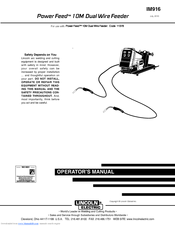
Lincoln Electric POWER FEED 10M Operator's Manual (68 pages)
Dual Wire Feeder
Brand:
Lincoln Electric
| Category:
Welding System
| Size: 3 MB
Table of Contents
Electric and Magnetic Fields
2
California Proposition 65 Warnings
2
Table of Contents
7
Installation
9
Technical Specifications
9
Safety Precautions
10
Electrode Routing
10
Control Cable
10
Control Cable Connections
10
Output Cable, Connections and Limitations
11
Negative Electrode Polarity
11
Voltage Sensing
12
Wire Drive Gear Ratio (High or Low Speed
13
Selecting the Proper Gear Ratio
13
Changing the Wire Drive Ratio
14
Ratio Change Procedure
14
Gear Ratio Recognition
14
Wire Feed Drive Roll Kits
15
Procedure to Install Drive Rolls and Wire Guides
15
Gun and Cable Assemblies with Standard Connection
15
Gun and Cable Assemblies with Fast-Mate Connection
15
General Gun Connection Guidelines
16
GMAW Shielding Gas
16
Wire Spindle Placement
17
Water Connections (for Water Cooled Guns
17
Wire Feed Shut down Circuit (Optional
17
Examples of Connecting an Arclink Power Wave System
18
Operation
19
Safety Precautions
19
Definition of Welding Modes
19
Common Welding Abbreviations
19
Product Description
20
Recommended Processes and Equipment
20
1 Wire Feed Speed (Wfs) / Amp Meter
21
Operational Features and Controls
21
2 Volt / Trim Meter
21
3 Output Controls
22
Layout-Controls
23
Operation
23
Power-Up Sequence
23
Accessing the Machine Setup Menu
24
Machine Setup/User Preferences
24
Set-Up Feature Menu
25
User Defined Parameters
26
Dual Head/Dual Procedure with Memory
34
Step / 4 Step Operation
35
Cold Feed/Gas Purge Switch
36
Electrode Polarity
37
Foot Amptrol
37
Hot Inch
37
Wire Drive PC Board Adjustments
37
Wire Reel Loading
37
Drive Roll Pressure Setting
39
Feeding Electrode and Brake Adjustment
39
Gas Guard Regulator Setting
39
Procedure for Setting Angle of Feedplate
39
Making a Weld
40
Wire Feed Overload Protection
40
Wire Reel Changing
40
Component Status Lights
41
Status Light States
41
Limit Settings
43
Accessories
44
Drive Roll and Guide Tube Kits
44
Field Installed Options/Accessories
45
Guns and Gun Adapters
46
Conduit Adapters
47
Dual Procedure Switch Options
47
Making a Weld with the Prince Xl or Cobra Gold Torch Installed
48
Avoiding Wire Feeding Problems
49
Maintenance
49
Periodic Maintenance
49
Procedure for Removing Feedplate from Wire Feeder
49
Routine Maintenance
49
Safety Precautions
49
How to Use Troubleshooting Guide
50
Step 2. POSSIBLE CAUSE
50
Troubleshooting
52
Error Codes for the Power Wave
59
Diagrams
62
4 Dual Procedure / Dual Head Select W/Memory Panel
22
5 Mode Select Panel 4 (MSP4
22
Lincoln Electric POWER FEED 10M Operator's Manual (72 pages)
Single Bench
Brand:
Lincoln Electric
| Category:
Welding Accessories
| Size: 2 MB
Table of Contents
Electric Shock Can Kill
3
Table of Contents
7
Installation
9
Technical Specifications
9
Safety Precautions
10
Location
10
Mounting
10
Weld Cable Sizing
10
Weld Cable Connection
10
Coaxial Weld Cables
11
Changing Electrode Polarity
12
Negative Electrode Polarity
12
Cables
13
Digital Control Cable
13
Welding Gun/Wire Feeder Trigger Connector
13
Wire Drive Systems
14
Changing Drive Rolls and Wire Guides
14
Drive Roll Pressure Setting
15
Changing the Gun Receiver Bushing
15
Welding Gun Torch and Accessories
16
Wire Feed Shut down Circuit
17
Changing the Gear Ratio
17
Wire Reel Loading
18
Shielding Gas Connection
21
Examples of Connecting an Arclink Power Wave System
22
Operation
23
Safety Precautions
23
Graphic Symbols
23
Definitions of Welding Modes
23
Product Description
24
Bench Model Features
25
Basic POWER FEED 10M Single Wire Feeder Welding System Configuration
25
Front Panel Controls and Connections
26
1 Status LED
27
2 Digital Meters and Output Encoder Knobs
27
Synergic CV Voltage Display
28
Overview
29
3 Mode Select Panel 4 (MSP4
29
Layout-Controls
29
Layout-Digital Displays
29
Power-Up Sequence
30
Changing Weld Modes
30
Changing Arc Wave Control
30
Changing Weld Sequence Behavior
30
Infrared (IR) Control
30
Lockout/Security
30
Limit Setting
31
Machine Setup/User Preferences
31
Accessing the Machine Setup Menu
31
Setup Features Menu
32
4 Cold Feed / Gas Purge Switch
40
5 2-Step/4- 4 Step Trigger Switch Operations
43
Process Setup and Operation
43
Steel and Stainless Synergic GMAW-P (Pulsed MIG) Welding
44
Arc Control
44
Operation
44
Aluminum Synergic Gmaw-P (Pulsed Mig)And Gmaw-Pp (Pulse on Pulse) Welding
45
Machine Functionality by Weld Process
46
GTAW (TIG) Welding
51
Weld Mode Searching
52
User Memories
52
6 Optional Dual Procedure/Memory Panel Operation
53
Limit Setting
53
Accessories
55
Maintenance
58
Safety Precautions
58
Routine Maintenance
58
Periodic Maintenance
58
Calibration Specification
58
Troubleshooting
59
How to Use Troubleshooting Guide
59
Lincoln Electric POWER FEED 10M Operator's Manual (89 pages)
Brand:
Lincoln Electric
| Category:
Welding System
| Size: 12 MB
Table of Contents
Special Situations
2
Electric Shock Can Kill
4
General Description
8
Installation
9
INPUT VOLTAGE and CURRENT
9
Physical Dimensions
9
Temperature Range
9
Safety Precautions
10
High Frequency Protection
10
Cable Connections
11
Shielding Gas Connection
13
Wire Drive Configuration
14
Procedure to Install Drive Rolls and Wire Guides
14
Remote Sense Lead Specifications
15
Loading Spools of Wire
15
Typical System Configurations
16
Definition of Welding Terms
18
Duty Cycle
18
Non-Synergic Welding Modes
18
Case Front Controls
19
On/Off Switch
20
Status Led
20
Smaw (Stick) Welding
22
Steel and Stainless Synergic Gmaw-P (Pulsed Mig) Welding
27
Display Operation
29
Aluminum Synergic Gmaw-P (Pulsed Mig)And Gmaw-Pp (Pulse on Pulse) Welding
30
Gtaw (Tig) Welding
33
Weld Mode Searching
34
Setup Menu Features
35
User Defined Parameters
36
User Memories
47
Internal Controls
50
Cold Feed/Gas Purge Switch
51
Pressure Arm Adjustment
51
Light Switch
51
Heater Switch
51
Factory Installed Equipment
59
Drive Roll Kits Used
59
Routine Maintenance
64
Periodic Maintenance
64
Calibration Specification
64
Troubleshooting
65
Step 2. POSSIBLE CAUSE
65
Lincoln Electric POWER FEED 10M Operator's Manual (83 pages)
Brand:
Lincoln Electric
| Category:
Welding System
| Size: 7 MB
Table of Contents
Table of Contents
7
Installation
8
Technical Specifications
8
Safety Precautions
9
Location
9
High Frequency Protection
9
Arclink Control Cable
10
Cable Connections
10
Weld Cable Sizes
11
Coaxial Weld Cable
11
Electrode Polarity
12
Shielding Gas Connection
12
Wire Drive Configuration
14
Procedure to Install Drive Rolls and Wire Guides
14
Remote Sense Lead Specification
15
Loading Spools of Wire
15
Typical System Configurations
16
Operation
17
Safety Precautions
17
Graphic Symbols that Appear on this Machine or in this Manual
17
Definition of Welding Terms
18
General Description
18
Duty Cycle
18
Case Front Controls
21
9. ON/OFF Switch
21
Making a Weld with Waveform Technology Power Sources
23
Procedure/Memory Panel Operation
49
Dual Procedure/Memory Operation
52
Cold Feed / Gas Purge Switch, Light Switch, Heater Switch, Pressure Arm Adjustment
57
Rear Controls
64
Flow Meter
65
Operation on Lincnet Power Sources
65
Accessories
66
Factory Installed Equipment
66
Drive Roll Kits Used
66
Water Cooled Guns
71
Maintenance
72
Safety Precautions
72
Routine Maintenance
72
Periodic Maintenance
72
Calibration Specification
72
Troubleshooting
73
How to Use Troubleshooting Guide
73
Lincoln Electric POWER FEED 10M Service Manual (108 pages)
Lincoln Electric Welder User Manual
Brand:
Lincoln Electric
| Category:
Welding System
| Size: 8 MB
Table of Contents
Power Feed
1
Return to Main Menu
8
Power Source
12
W Ire Feeder
12
Start Options
26
CC Stick Soft
26
Arc Control
26
Weld Modes
37
Set Limits
48
Shielding Gas
53
Lincoln Electric POWER FEED 10M Operator's Manual (83 pages)
Lincoln Electric Welder User Manual
Brand:
Lincoln Electric
| Category:
Welding System
| Size: 7 MB
Table of Contents
Power Source
10
Wire Feeder
10
Set Limits
50
Shielding Gas
60
Lincoln Electric POWER FEED 10M Manual (9 pages)
Brand:
Lincoln Electric
| Category:
Welding System
| Size: 0 MB
Table of Contents
Waveform Control Technology
1
What Is Waveform Control?
2
How Waveform Control Works
2
Waveform Control Weld Programs
3
Aluminum Weld Programs
4
Stainless Steel Weld Programs
4
Alloy Weld Programs
4
Metal Core Weld Programs
4
Using Waveform Control
5
Arc Control: Controlling the Waveform
5
Waveform Control Software
5
Wavedesigner
5
Arcscope
5
Custom Waveforms
5
Process Controls
6
Pulse-On-Pulse™
6
Stt®
6
Power Mode™
6
Tandem MIG
6
AC/DC Submerged Arc
6
Waveform Control Products
7
Power Wave 355/Power Feed™ 10M
7
Power Wave 455M
7
Power Wave 455M/STT
7
Power Wave 655R
7
Power MIG 300
7
Power Wave AC/DC 1000
8
Power Wave F355I
8
What Is Nextweld?
8
Advertisement
Related Products
Lincoln Electric LINC FEED 34
Lincoln Electric LINC FEED 35
Lincoln Electric LINC FEED 37
Lincoln Electric LINC FEED 38
Lincoln Electric Power Feed 10
Lincoln Electric Power Feeder 10
Lincoln Electric LINC FEED 45
Lincoln Electric POWER FEED 25M ALUMINUM
Lincoln Electric Power Feed 84 U.I. Control Box
Lincoln Electric LINC FEED 40
Lincoln Electric Categories
Welding System
Welding Accessories
Flashlight
Wire Feeders
Portable Generator
More Lincoln Electric Manuals
Login
Sign In
OR
Sign in with Facebook
Sign in with Google
Upload manual
Upload from disk
Upload from URL