Lincoln Electric Power Feed 10 Manuals
Manuals and User Guides for Lincoln Electric Power Feed 10. We have 4 Lincoln Electric Power Feed 10 manuals available for free PDF download: Service Manual, Operator's Manual
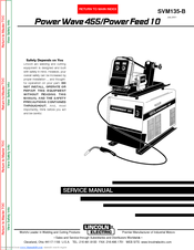
Lincoln Electric Power Feed 10 Service Manual (182 pages)
Lincoln Electric Welder User Manual
Brand: Lincoln Electric
|
Category: Welding System
|
Size: 3 MB
Table of Contents
Advertisement
Lincoln Electric Power Feed 10 Service Manual (182 pages)
Brand: Lincoln Electric
|
Category: Welding System
|
Size: 4 MB
Table of Contents

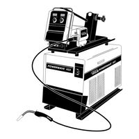
Lincoln Electric Power Feed 10 Operator's Manual (68 pages)
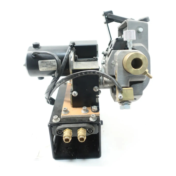
Wire Drive & Control Box Boom Mount or Bench Model
Brand: Lincoln Electric
|
Category: Welding System
|
Size: 0 MB
Table of Contents
Advertisement

Lincoln Electric Power Feed 10 Operator's Manual (29 pages)
Brand: Lincoln Electric
|
Category: Wire Feeders
|
Size: 0 MB
Table of Contents
Advertisement
Related Products
- Lincoln Electric POWER FEED 10M
- Lincoln Electric LINC FEED 34
- Lincoln Electric LINC FEED 35
- Lincoln Electric LINC FEED 37
- Lincoln Electric LINC FEED 38
- Lincoln Electric Power Feeder 10
- Lincoln Electric LINC FEED 45
- Lincoln Electric POWER FEED 25M ALUMINUM
- Lincoln Electric Power Feed 84 U.I. Control Box
- Lincoln Electric LINC FEED 40