Sign In
Upload
Manuals
Brands
Keysight Technologies Manuals
Measuring Instruments
N432A
Keysight Technologies N432A Manuals
Manuals and User Guides for Keysight Technologies N432A. We have
2
Keysight Technologies N432A manuals available for free PDF download: User Manual
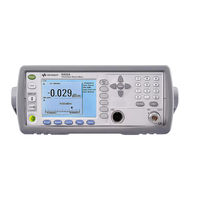
Keysight Technologies N432A User Manual (154 pages)
Thermistor Power Meter
Brand:
Keysight Technologies
| Category:
Measuring Instruments
| Size: 1 MB
Table of Contents
Table of Contents
13
1 Introduction
23
LXI Class-C Compliant N432A
24
Sensor Compatibility
25
Conventions Used in this Guide
26
Front Panel Outlook
27
Rear Panel Connections
32
Display Layout
33
Figure 1-1 Dual Numeric Display
33
Figure 1-2 Single Numeric and Analog Display
34
Figure 1-3 Full Screen Numeric Display
35
Window Symbols and Pop-Ups
37
Warning Symbol Pop-Up
37
Wait Symbol Pop-Up
38
Confirm Symbol Pop-Up
38
Numeric Entry Pop-Up
38
Text Entry Pop-Up
39
List Pop-Up
39
Using the N432A Web Interface
40
Figure 1-4 Accessing the N432A Web Interface from the Connection Expert
40
Figure 1-5 N432A Web Interface (Welcome Page)
41
Figure 1-6 Blinking Message to Identify the N432A
42
Figure 1-7 Example of the Lan Status Message
42
Table 1-1 Lan Status Messages
43
Figure 1-8 Virtual Front Panel
44
Using the Remote Front Panel
44
Editing the N432A LAN Settings
45
Figure 1-10 Enter Password Dialog Box
45
Figure 1-9 Viewing the Current LAN Configuration from the Web Interface
45
Figure 1-11 Changing the N432A LAN Interface Configuration
46
Capturing the Screen Image
47
Figure 1-12 Screen Capture
47
Figure 1-13 Obtaining Instrument Data
48
Getting the Instrument Data
48
Making the Socket Connection
49
Figure 1-14 Add Instrument Dialog
49
Figure 1-15 Add LAN Instruments Dialog
50
Figure 1-16 N432A Connected Via the Socket Connection
50
2 Operating Information
51
Setting the Bridge Resistance
52
Figure 2-1 Bridge Resistance Pop-Up List
52
Setting the Resistance Type
53
Figure 2-2 Connections for Ruser Measurement
53
Figure 2-3 Resistance Type Pop-Up List
54
Figure 2-4 Ruser Pop-Up
54
Setting the Measurement Unit
56
Table 2-1 Measurement Units
56
Setting the Measurement Frequency
57
Figure 2-5 Frequency Pop-Up
58
Setting the Resolution
59
Displaying Voltage Measurements
60
Figure 2-6 Voltage Measurement Display
60
Making Relative Measurements
61
Figure 2-7 Typical Relative Measurement Display
61
Setting Offsets
63
Figure 2-8 Simplified Measurement Path
63
Figure 2-9 Setting the Channel Offset
64
Setting the Channel Offset
64
Figure 2-10 Offset Indicator
65
Setting the Display Offset
65
Figure 2-11 Setting the Display Offset
66
Setting the Frequency-Dependent Offset
67
Figure 2-12 Frequency-Dependent Offset Tables
68
Figure 2-13 Frequency-Dependent Offset Table Indicator
68
Figure 2-14 Edit Offset Display with Data Added
70
Figure 2-15 Edit Table Name Pop-Up
70
Figure 2-16 Setting the Offset Unit
71
Figure 2-17 Offset Display in the Engineering Unit (When the Selected Unit Is %)
73
Setting the Voltage Averaging
74
Figure 2-18 Volt Avg Pop-Up List
74
Step Detection
75
Setting Measurement Limits
76
Table 2-2 Range of Values for Window Limits
76
Figure 2-19 Minimum Limit Pop-Up
77
Figure 2-20 Meter Minimum Pop-Up
77
Checking for Limit Failures
78
Figure 2-21 Limit Failures
78
Single Function Measurement
79
Figure 2-22 Single Function Measurement Configuration
79
Figure 2-23 Function Pop-Up List
79
Combined Measurement
80
Figure 2-24 Combined Measurement Configuration
80
Figure 2-25 Measurement Display Example
81
Max Hold/Min Hold
82
Figure 2-26 Max Hold/Min Hold Measurement Performed on the 'HOLD' Block
82
Figure 2-27 Hold Pop-Up List
83
Figure 2-28 Min Hold and Max Hold Measurement Modes Indicated on the
83
Figure 2-29 Min Hold Indicated in Full in the Expanded Window
84
Recorder Output
85
Figure 2-30 Recorder Output Pop-Up List
85
Figure 2-31 Recorder Minimum Pop-Up
86
Figure 2-32 Recorder Maximum Pop-Up
86
Table 2-3 Ranges of the Recorder Output Setting
87
Saving and Recalling N432A States
88
Figure 2-33 Save/Recall Screen
88
Figure 2-34 Save Confirmation Pop-Up Dialog
88
Editing a Register Name
89
Figure 2-35 File Name Pop-Up
89
Recalling a Measurement Setup
89
Figure 2-36 Recall Confirmation Pop-Up Dialog
90
Zeroing the N432A
91
Figure 2-37 Zeroing Pop-Up Message
91
Using the Calibration/Correction Factors
92
Frequency-Specific Calibration Factors
92
Figure 2-38 Cal Factor Pop-Up
92
Sensor Calibration Tables
93
Selecting a Sensor Calibration Table
93
Figure 2-39 Sensor Table Selected
94
Figure 2-40 Sensor Calibration Table Indicator
94
Editing/Generating Sensor Calibration Tables
95
Figure 2-41 Sensor Tbls Screen
96
Table 2-4 Installed Thermistor Sensor Models
96
Figure 2-42 Edit Cal Display
97
Figure 2-43 Edit Table Title Pop-Up
97
Power Measurement Procedures
99
Internal Power Measurement
99
Precision Power Measurement
101
Figure 2-44 Connection Diagram for Precision Power Measurement
102
Voltage Standing Wave Ratio (VSWR) Measurement
104
Figure 2-45 Connection Diagram for VRC Measurement
106
Figure 2-46 Connection Diagram for VSWR Measurement
108
Blank Screen
110
Figure 2-47 Blank Screen Feature
110
Secure Blank
111
Figure 2-48 Secure Blank Feature
111
Figure 2-49 Enter 6-Digit Password Pop-Up
111
Figure 2-50 Warning Message
112
Figure 2-51 Reconfirm Password Pop-Up
112
Figure 2-52 Warning Message
112
Figure 2-53 Password Reconfirmation Pop-Up
113
Figure 2-54 Password Required to Restore Display
113
Backlight Intensity Control
114
Figure 2-55 Backlight Intensity Control Feature
114
Figure 2-56 Increase or Decrease the Backlight Brightness
114
Memory Erase/Secure Erase
115
Figure 2-57 Activate Memory Erase Using Combo Keys
115
Figure 2-58 Secure Erase Feature
116
Figure 2-59 Confirmation to Begin Secure Erase
116
Figure 2-60 Warning Message Displaying the Secure Erase Status
116
Warm Start
117
Figure 2-61 Warm Start On/Off Feature
117
3 Maintenance
119
Self-Test
120
Front Panel Selection of Self-Tests
120
Instrument Self-Test
121
Figure 3-1 Self-Test Completed
121
Remote Testing
123
Test Descriptions
123
Error Messages
125
Introduction
125
Figure 3-3 Error Indicator
125
Error List
127
Operator Maintenance
134
Checking the Power Line Fuses
134
Figure 3-4 Checking the Fuses
134
Contacting Keysight Technologies
135
Prior to Contacting Keysight Technologies
135
Check the Basics
136
Instrument Serial Numbers
136
Recommended Calibration Interval
137
Erasing Memory Data
138
Figure 3-5 Secure Erase Status Pop-Up
138
Returning the N432A for Service
139
Packaging the N432A for Shipment
139
Keysight Sales and Service Offices
140
4 Specifications and Characteristics
141
Introduction
142
Specification Definitions
142
N432A Specifications
144
Rear Panel Input and Output Connections
146
Line Power
146
Mw Power Reference
147
Environmental Conditions
148
General
148
Operating Environment
148
Storage
148
Physical Characteristics
149
Dimensions
149
Weight
149
Regulatory Information
150
Electromagnetic (EM) Compatibility
150
Product Safety
150
Low Voltage Directive
151
Advertisement
Keysight Technologies N432A User Manual (137 pages)
Thermistor Power Meter
Brand:
Keysight Technologies
| Category:
Measuring Instruments
| Size: 2 MB
Table of Contents
Certification
3
General Warranty
3
Warranty Service
3
Limitation of Warranty
4
Exclusive Remedies
4
Restricted Rights Legend
5
Technology Licenses
5
Safety Symbols
6
Safety Considerations
7
Recommended Calibration Interval
7
General Safety Information
8
Regulatory Markings
10
South Korean Class a EMC Declaration
11
Safety and EMC Requirements
11
Waste Electrical and Electronic Equipment (WEEE) Directive
12
Sales and Technical Support
12
Table of Contents
13
Introduction
17
LXI Class-C Compliant N432A
18
Sensor Compatibility
19
Conventions Used in this Guide
20
Front Panel Outlook
21
Rear Panel Connections
26
Display Layout
27
Window Symbols and Pop-Ups
31
Using the N432A Web Interface
34
Making the Socket Connection
42
Operating Information
45
Setting the Bridge Resistance
46
Setting the Resistance Type
47
Setting the Measurement Unit
49
Setting the Measurement Frequency
50
Setting the Resolution
52
Displaying Voltage Measurements
53
Making Relative Measurements
54
Setting Offsets
56
Setting the Voltage Averaging
67
Step Detection
68
Setting Measurement Limits
69
Single Function Measurement
72
Combined Measurement
73
Max Hold/Min Hold
75
Recorder Output
77
Saving and Recalling N432A States
80
Zeroing the N432A
83
Using the Calibration/Correction Factors
84
Power Measurement Procedures
91
Voltage Standing Wave Ratio (VSWR) Measurement
96
Blank Screen
102
Secure Blank
103
Backlight Intensity Control
106
Memory Erase/Secure Erase
107
Warm Start
109
Maintenance
111
Self-Test
112
Error Messages
116
Operator Maintenance
123
Contacting Keysight Technologies
124
Erasing Memory Data
127
Returning the N432A for Service
128
Specifications and Characteristics
130
Introduction
130
N432A Specifications
132
Rear Panel Input and Output Connections
133
Mw Power Reference
134
Environmental Conditions
134
Physical Characteristics
135
Advertisement
Related Products
Keysight Technologies N437 Series
Keysight Technologies N4373D
Keysight Technologies N4373B
Keysight Technologies N4374B
Keysight Technologies N4375B
Keysight Technologies N4376D
Keysight Technologies N4375D
Keysight Technologies N4376B
Keysight Technologies N4960A
Keysight Technologies N4373E
Keysight Technologies Categories
Measuring Instruments
Test Equipment
Control Unit
Portable Generator
Power Supply
More Keysight Technologies Manuals
Login
Sign In
OR
Sign in with Facebook
Sign in with Google
Upload manual
Upload from disk
Upload from URL