Sign In
Upload
Manuals
Brands
IAI Manuals
Security Camera
SP-20000C-CXP2
IAI SP-20000C-CXP2 Manuals
Manuals and User Guides for IAI SP-20000C-CXP2. We have
2
IAI SP-20000C-CXP2 manuals available for free PDF download: User Manual
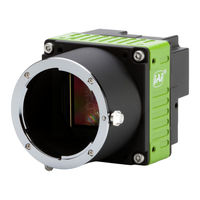
IAI SP-20000C-CXP2 User Manual (89 pages)
20 MP CMOS Digital Progressive Scan Monochrome and Color Camera Spark Series
Brand:
IAI
| Category:
Security Camera
| Size: 2.91 MB
Table of Contents
Sp-20000M-Cxp2 / Sp-20000C-Cxp
2
Table of Contents
5
Introduction
8
General
9
Camera Composition
9
Key Features
10
Parts Locations and Their Functions
11
Rear Panel
12
Input and Output
13
Coaxpress Interface Standard
13
Connectors and Pin Assignment
14
Digital Video Output (75Ω 1.0・2.3 DIN Receptacle)
14
12-Pin Connector
14
Figure
14
Pin Configuration
14
AUX Connector Hirose 10-Pin Connector
15
Digital in and out Inteface
15
Line Selector
15
Line Source
16
Line Mode
17
Line Inverter
17
Line Status
17
Line Format
17
Gpio
18
Basic Block Diagram
18
Input and Output Matrix Table
19
5.4 Optical Interface
20
Recommended External Input Circuit Diagram for Customer
20
Recommended External Output Circuit Diagram for Customer
20
Characteristics of Optical Interface
21
Pulse Generator
21
Clock Pre-Scaler
22
Pulse Generator Selector
22
Pulse Generator Length
22
Pulse Generator Start Point
22
Pulse Generator End Point
23
Pulse Generator Repeat Count
23
Pulse Generator Clear Activation
23
Pulse Generator Clear Sync Mode
23
Pulse Generator Clear Source
24
Pulse Generator Inverter
25
Pulse Generator Setting Parameters
25
Associated Genicam Register Information
26
Sensor Layout, Output Format and Timing
27
Sensor Layout
27
Monochrome Sensor
27
Bayer Sensor
27
Camera Output Format (Tap Geometry)
28
Output Timing and Output Image
29
Horizontal Timing
29
Vertical Timing
32
ROI (Region of Interest)
33
Mirroring Function
35
Multi ROI Function
36
Multi ROI Setting Parameters
36
Associated Genicam Register Information
38
Digital Output Bit Allocation
38
Operating Modes
39
Acquisition Control (Change the Frame Rate)
39
Acquisition Control
39
The Relationship between Link Configuration and Acquisition Frame Rate
39
7.1.3 Calculation of Frame Rate(In Continuous Trigger Mode
40
Associated Genicam Register Information
40
Exposure Control
40
Exposure Mode
40
Exposuretime
42
Behavior if Trigger Overlap Is Set to Readout
42
Exposureauto
44
Trigger Operation
45
Trigger Selector
45
Trigger Mode
45
Triggersource
46
Triggeractivation
46
Triggeroverlap
47
Associated Genicam Register Information
47
Normal Continuous Operation (Timed Exposure Mode/Trigger Mode OFF)
48
Timed Mode (EPS)
48
If Overlap Setting Is off
49
If Overlap Setting Is Readout
50
GPIO TTL Output Timing if Trigger Overlap Is off
52
GPIO TTL Output Timing if Trigger Overlap Is Readout
53
Trigger Width Mode (PWC)
54
If Overlap Setting Is off
55
If Overlap Setting Is Readout
56
Minimum Trigger Interval Calculation Formula (Trigger Overlap = OFF)
57
Minimum Trigger Interval Calculation Formula (Trigger Overlap = Readout)
58
PIV (Particle Image Velocimetry)
59
Sequence ROI Trigger
63
Typical Minimum Trigger Interval of Sequence ROI Trigger
64
Operation and Function Matrix
69
Other Functions
70
Black Level Control
70
Black Level Selector
70
Black Level
70
Auto Black Control
70
Associated Genicam Register Information
71
Gain Control
71
Gain Selector
72
Gain
72
Gain Auto
72
Balance White Auto
72
Associated Genicam Register Information
73
Lut
74
LUT Enable
74
LUT Index
74
LUT Value
74
Associated Genicam Register Information
74
Gamma
75
Shading Correction
75
Blemish Compensation
76
Alc
77
HDR Function (Option)
79
Camera Settings
81
Camera Control Tool
81
Camera Default Settings
81
External Appearance and Dimensions
82
Specifications
83
Camera Spectral Response
83
Specification Table
84
Appendix
86
Precautions
86
Typical Sensor Characteristics
86
Caution When Mounting a Lens on the Camera
86
Caution When Mounting the Camera
86
Exportation
87
References
87
Manual Change History
88
User's Record
89
Advertisement
IAI SP-20000C-CXP2 User Manual (98 pages)
CMOS Digital Progressive Scan Monochrome and Color Camera
Brand:
IAI
| Category:
Digital Camera
| Size: 2.51 MB
Table of Contents
Table of Contents
2
About Technical Note
4
Notice/Warranty
5
Notice
5
Warranty
5
Certifications
5
CE Compliance
5
Fcc
5
Warning
6
China Rohs
7
Usage Precautions
8
Emva1288
8
Interface
8
Frame Grabber Board
8
Notes on Coaxial Cables
8
Notes on Exportation
8
Features
9
Parts Identification
11
① Lens Mount (F-Mount or M42-Mount)
11
② AUX Connector (10-Pin)
12
③ Power/Trig Led
13
④ DC in / Trigger in Connector (12-Pin Round)
13
⑤ Link-1 / Link-2 Led
14
⑥ CXP-1 / CXP-2 Connectors
14
⑦ ⑧ Mounting Holes (M3)
15
Main Functions
16
Coaxpress Interface Standard
16
GPIO (Digital Input/Output Settings)
18
Input and Output Matrix Table
21
Optical Interface
22
Pulse Generator
24
Pulse Generator Setting Parameters
27
Sensor Layout
28
Camera Output Format (Tap Geometry)
29
Output Timing
30
Horizontal Timing
30
Horizontal Formats in Continuous Trigger
31
Vertical Timing
33
Continuous Trigger Vertical Timing
34
ROI (Regional Scanning Function)
36
ROI Setting Examples
37
Mirroring Function
38
Multi ROI Function
39
Multi ROI Setting Parameters
39
Digital Output Bit Allocation
41
Acquisition Control (Change the Frame Rate)
42
Calculation of Frame Rate (in Continuous Trigger Mode)
43
Exposure Mode
44
Exposuretime
45
Behavior if Trigger Overlap Is Set to Readout
46
Exposureauto
48
Trigger Control
49
Normal Continuous Operation (Timed Exposure Mode/Trigger Mode OFF)
51
Timed (EPS) Mode
52
Trigger Overlap = off (Timed Mode)
53
Trigger Overlap = Readout (Timed Mode)
55
GPIO TTL Output Timing (Trigger Overlap = Off, Timed Mode)
57
GPIO TTL Output Timing (Trigger Overlap = Readout, Timed Mode)
59
Triggerwidth Mode
61
Trigger Overlap = off (Triggerwidth Mode)
62
Trigger Overlap = Readout (Triggerwidth Mode)
64
PIV (Particle Image Velocimetry)
67
Sequence ROI Trigger
72
Sequence ROI Setting Parameters
74
Operation and Function Matrix
78
Black Level Control
79
Gain Control
80
Gain Auto
81
Balance White Auto
82
LUT (Lookup Table)
83
Gamma Function
84
Shading Correction
84
Blemish Compensation
86
ALC (Automatic Level Control)
87
Miscellaneous
89
Troubleshooting
89
Specifications
90
Spectral Response
94
Dimensions
95
F-Mount Model
95
M42-Mount Model
96
User's Record
97
Revision History
98
Advertisement
Related Products
IAI SP-20000M-CXP2
IAI SP-20000C-USB
IAI SP-20000M-USB
IAI SP-20000M-PMCL
IAI SP-20000C-PMCL
IAI SCON-CA
IAI SCON-LC-F
IAI ELECYLINDER S13X
IAI SW-4000T-MCL
IAI SW-4000TL-10GE
IAI Categories
Controller
Digital Camera
Security Camera
Gateway
Industrial Equipment
More IAI Manuals
Login
Sign In
OR
Sign in with Facebook
Sign in with Google
Upload manual
Upload from disk
Upload from URL