Sign In
Upload
Manuals
Brands
Hypertherm Manuals
Welding System
Powermax45 SYNC
Hypertherm Powermax45 SYNC Manuals
Manuals and User Guides for Hypertherm Powermax45 SYNC. We have
5
Hypertherm Powermax45 SYNC manuals available for free PDF download: Service Manual, Operator's Manual, Getting Started Manual, Field Service Bulletin, User Manual
Hypertherm Powermax45 SYNC Manual
Brand:
Hypertherm
| Category:
Welding System
| Size: 3 MB
Table of Contents
In the box
Set up the system
Step 1 - Connect to power
Voltage configurations
Prepare the power cord
Step 2 - Connect the gas supply
Gas requirements
Operate the system
Step 1 – Connect the torch lead
Step 2 – Connect the work lead and work clamp
Step 3 - Choose a cartridge
Step 4 – Install the cartridge
Step 5 – Set the power switch to ON (I)
Step 6 - Unlock and fire the torch
Adjust the output amperage if necessary
Use the SmartSYNC hand torch
Torch status
Cut, pierce, and gouge metal
Cut
Rolling pierce
Gouge
Troubleshoot common problems
Identify when to install a new cartridge
Identify problems with cut quality - mild steel
Optimal cut quality
Too much of a bevel angle
Hardened dross
Identify common system problems
Do a gas test
Enter gas test mode
When gas test mode is active
Exit gas test mode
Identify common fault conditions
Documents / Resources
References
Advertisement
Hypertherm Powermax45 SYNC Service Manual (218 pages)
Brand:
Hypertherm
| Category:
Welding System
| Size: 31 MB
Table of Contents
Safety Information
5
Table of Contents
6
Electromagnetic Compatibility (EMC)
15
Screening and Shielding
16
Warranty
17
Patent Indemnity
17
Limitation of Liability
17
National and Local Codes
18
Liability Cap
18
Waterjet Product Warranty Coverage
18
Prepare to Troubleshoot Internal Components
19
Where to Find Information for Powermax45 SYNC
19
Troubleshooting Preparation
19
Troubleshooting Procedures and Sequence
21
Required Test Equipment
22
Do an External Inspection
22
Do an Internal Inspection
23
Attach to Ground
23
Frequently Used Troubleshooting Procedures
24
Restart the Plasma Power Supply
24
Do a Cold Restart
24
Do a Quick Restart
24
Troubleshooting for Gas Pressure Problems
24
Install a Pressure Gauge
24
Monitor the Inlet Gas Supply
25
Use a Gas Hose that Is the Correct Size
25
Adjust the Pressure Manually
25
Do a Gas Test to Find if the Output Gas Pressure Is too Low
25
Keep a Clean Gas Line
25
Do a Gas Test
27
Stop a Gas Test
28
Do a Continuity Test on the Fastconnect Torch Receptacle
28
Do an Initial Resistance Check
29
Troubleshooting for Common Problems
35
The Cut Quality Is Unsatisfactory, or the Cut Does Not Sever the Workpiece
36
There Is a Problem with the Hypertherm Cartridge
36
The Work Lead Connection Is Not Satisfactory
36
The Output Current (A) Is Set too Low
37
The Operating Mode Is Incorrect
37
An Extension Cord Is Not Sufficient
37
The Power PCB Is Defective
37
The Power Switch Is Set to ON, but the Power LED Is off
37
The Voltage to the System Is Missing or Incorrect
37
The Power Switch or Power PCB Is Defective
38
The Solenoid Valve Is Defective
38
The Fan Is Defective
38
The Power LED Is On, but no Gas Flows When You Fire the Torch
39
The Torch, Torch Lead, Power PCB, or Machine Interface Connection Has Damage
39
The Arc Does Not Transfer to the Workpiece
39
The Work Lead Connection Is Not Satisfactory
39
The Pierce Height Is too High
39
Gas Flows from the Torch When You Set the Power Switch to on
40
The Incoming Gas Pressure Is too High
40
The Solenoid Valve or Power PCB Is Defective
40
Gas Flows When You Fire the Torch, but There Is no Plasma Arc
40
There Is a Problem with the Hypertherm Cartridge, Torch, or Torch Lead
40
The Gas Flow Is too High or too Low
40
The Gas Quality Is Unsatisfactory
41
The Input Power Is Not Sufficient
41
There Is a Voltage Imbalance on the Capacitors
41
The Plasma Arc Goes out While You Are Cutting, or the Torch will Intermittently Not Fire
42
The Work Lead Is Defective or the Work Lead Connection Is Insufficient for some Reason
42
The Fan Is Defective
42
The Plasma Arc Stopped While Cutting, but Starts When You Fire the Torch Again
43
The Hypertherm Cartridge Is Worn or Has Damage
43
The Filter Element in the Air Filter Is Dirty
43
The Gas Pressure Is too Low or too High
43
The Plasma Arc Makes Sputtering and Hissing Sounds
44
The Air Filter Element Is Dirty
44
There Is Moisture in the Gas Supply Line
44
The System Is Not Cutting at Full Cutting Power, and the Plasma Arc Does Not Time out after 5 Seconds
44
The Work Lead Connection Is Not Satisfactory
44
The Work Lead Has Damage
44
The Output Current Is Set too Low
45
The Power PCB Is Defective
45
Nothing Shows on the 2-Digit Display, the Power Switch Is Set to on (I), and the Power on LED Is on
45
There Is a Problem with the Voltage or the Power Source
45
The Fan Has a Short Circuit
45
The System Changes the Gas Pressure after You Set It Manually
46
One of These Conditions Caused the Gas Pressure to be Changed
46
The System Changes the Output Current (A) or the Operating Mode after You Set Them
46
You Selected the System Setting While the Torch was Locked
46
The Plasma Power Supply Stops (1-Phase Models)
47
The System Energized the Trip Coil, or the Power Switch Is Defective
47
Troubleshooting for Fault Codes
49
Fault Icons and Fault Codes
49
Fault Icons
49
Fault Codes
50
Operational Faults
51
Internal Component Faults (1-Nn-N, 2-Nn-N, 3-Nn-N)
56
Troubleshooting Procedures for Fault Leds and 0-Nn-N Fault Codes
58
Troubleshooting for AC Input Power that Is Not Stable
58
Fault Codes and Fault Leds
59
Corrective Action for AC Input Power that Is Not Stable
59
Troubleshooting for Low Gas Pressure Faults
59
Corrective Action - Gas Supply Checks
59
Corrective Action - more External Checks
60
Corrective Action - Internal Checks
61
Verification
61
Troubleshooting for Missing Gas Input Faults
61
Fault Codes and Fault Leds
61
Corrective Action for the Input Gas Supply
61
Corrective Action for the Solenoid Valve and Power PCB
62
Troubleshooting for TSO and TSC Faults
64
Fault Codes and Fault Leds
65
Corrective Action for the Hypertherm Cartridge
65
Corrective Action for TSO Faults that Occur During Postflow
65
Corrective Action for the Torch
67
Corrective Action for the Plasma Power Supply
68
Verification
70
Troubleshooting for Temperature-Related Faults
70
Fault Codes and Fault Leds
70
Corrective Action for Temperature Faults
71
Troubleshooting for When the Hypertherm Cartridge or Torch Is Not Ready to Cut
71
Fault Codes and Fault Leds
71
Corrective Action for the Hypertherm Cartridge and Torch
71
Corrective Action for the Torch Cap Sensor in the Torch and Torch Lead
72
Corrective Action for the Torch Cap Sensor in the Plasma Power Supply
74
Troubleshooting for Start Signal Faults
75
Fault Codes and Fault Leds
75
Corrective Action for Hand Torches
75
Corrective Action for Machine Torches and the CNC
78
Corrective Action for Machine Torches and the Plasma Power Supply
79
Troubleshooting for Input Voltage Faults
80
Fault Codes and Fault Leds
81
Corrective Action for the Incoming Line Voltage
81
Corrective Action for the Power PCB Voltage
85
Troubleshooting for Remote Controller Faults (0-11-N)
88
Fault Codes and Fault Leds
89
Corrective Action for 0-11-0, 0-11-1, and 0-11-2 Faults
89
Troubleshooting for Incorrect Output Gas Pressure Conditions (0-12-N)
89
Fault Codes and Fault Leds
90
Corrective Action for 0-12-0, 0-12-1, and 0-12-2 Faults
90
Troubleshooting for Hypertherm Cartridge Installation Faults (0-14-N)
90
Symptom
90
Fault Codes and Fault Leds
91
Correction Action for 0-14-0 Faults
91
Correction Action for 0-14-1 Faults
91
Troubleshooting for PCB Hardware Protection Faults (0-19-9)
92
Fault Codes and Fault Leds
92
Corrective Action for 0-19-9 Faults
92
Troubleshooting for Duty Cycle Faults (0-40-5)
93
Fault Codes and Fault Leds
93
Corrective Action for 0-40-5 Faults
93
Troubleshooting for Torch-Lock Switch Faults (0-50-N)
93
Fault Codes and Fault Leds
94
Corrective Action for 0-50-1 Faults
94
Corrective Action for 0-50-2 Faults
94
Corrective Action for 0-50-3 Faults
95
Troubleshooting for Torch Connection Faults (0-52-0)
95
Fault Codes and Fault Leds
95
Corrective Action for 0-52-0 Faults
95
Troubleshooting for an RF Communication Fault (0-98-1)
96
Fault Codes and Fault Leds
96
Corrective Action for the Hypertherm Cartridge (0-98-1)
96
Corrective Action for the Torch (0-98-1)
97
Troubleshooting for a Plasma Power Supply or Torch Communication Fault (0-98-2)
98
Fault Codes and Fault Leds
99
Corrective Action for the Plasma Power Supply (0-98-2)
99
Corrective Action for the Torch (0-98-2)
100
Troubleshooting Procedures for 1-Nn-N, 2-Nn-N, and 3-Nn-N Fault Codes
104
Troubleshooting for DSP and I/O Faults (1-Nn-N)
104
Fault Codes and Fault Leds
104
Corrective Action for 1-00-0 and 1-20-0 Faults
104
Troubleshooting for an Analog-To-Digital Converter Fault (2-00-0)
104
Fault Codes and Fault Leds
105
Corrective Action for 2-00-0 Faults
105
Troubleshooting for Inverter Module Temperature Sensor Faults (2-10-N)
105
Corrective Action for 2-10-0 and 2-10-1 Faults
106
Troubleshooting for Solenoid Valve Pressure Sensor Faults (2-11-N)
106
Fault Codes and Fault Leds
106
Corrective Action for Electrical Interference and Pinched Wires (2-11-0 and 2-11-1)
106
Corrective Action for the Power Input and Solenoid Valve Coils (2-11-0 and 2-11-1)
107
Corrective Action for the Solenoid Valve Sensor and Power PCB Sensor (2-11-0 and 2-11-1)
108
Troubleshooting for VBUS Faults (3-00-0)
109
Fault Codes and Fault Leds
109
Corrective Action for VBUS Faults Using Test Points (3-00-0)
109
Corrective Action for VBUS Faults Using the Capacitor Terminals (3-00-0)
112
Troubleshooting for Fan Faults (3-10-N)
113
Fault Codes and Fault Leds
113
Corrective Action for Fan Faults (3-10-0 and 3-10-1)
114
Troubleshooting for PFC Module Temperature Sensor Faults (3-11-N)
114
Fault Codes and Fault Leds
115
Corrective Action for 3-11-0, 3-11-1, and 3-11-2 Faults
115
Troubleshooting for Inverter IGBT Faults (3-51-1, 3-52-0)
115
Corrective Action for 3-51-1 and 3-52-0 Faults
115
Troubleshooting for a Power PCB Fault (3-60-0)
116
Fault Codes and Fault Leds
116
Corrective Action for 3-60-0 Faults
116
Service Parts
117
Replacement Parts and Accessories
117
Plasma Power Supply Interior, Power PCB
117
Plasma Power Supply Interior, Pneumatics and Fan
118
Plasma Power Supply Interior, Wires, CSA 1-Phase
119
Plasma Power Supply Interior, Wires and EMI PCB, CE/CCC 1-Phase
120
Plasma Power Supply Interior, Wires, 3-Phase
121
Safety Critical Parts
122
Recommended Spare Parts
124
Powermax45 SYNC Labels
125
Data Plate
125
Safety and EMC Symbols and Marks
126
IEC Symbols
128
Service Procedures for the Cover, Panels, and Connectors
131
Plasma Power Supply Component Replacement Safety Information
131
Replace the Plasma Power Supply Cover and Handle
132
Remove the Plasma Power Supply Cover and Handle
132
Install the Plasma Power Supply Cover and Handle
133
Replace the Component Barrier
135
Remove the Component Barrier
135
Install the Component Barrier
136
Remove and Install the Front Panel
138
Loosen the Front Panel
138
Remove the Front Panel
139
Attach the Front Panel
140
Remove and Install the Rear Panel
142
Loosen the Rear Panel
142
Remove the Rear Panel
142
Attach the Rear Panel
145
Replace the Work Lead Receptacle
147
Remove the Work Lead Receptacle
147
Install the Work Lead Receptacle
148
Replace the Torch Quick-Disconnect Receptacle
149
Remove the Torch Quick-Disconnect Receptacle
149
Install the Torch Quick-Disconnect Receptacle
150
Replace the Power Switch (1-Phase Models)
152
Remove the Power Switch (1-Phase)
152
Install the Power Switch (1-Phase)
153
Replace the Power Switch (3-Phase Models)
154
Remove the Power Switch (3-Phase)
154
Install the Power Switch (3-Phase)
154
Service Procedures for the Gas Supply
157
Replace the Air Filter Bowl and Filter Element
157
Replace the Air Filter Assembly
161
Remove the Air Filter
161
Install the Air Filter
162
Replace the Fan and Fan Shroud
162
Remove the Fan and Fan Shroud
162
Install the Fan and Fan Shroud
164
Replace the Solenoid Valve
166
Remove the Solenoid Valve
166
Install the Solenoid Valve
167
Replace the Gas Supply Hoses and 90 Degree Fitting
169
Remove the Gas Supply Hoses and 90 Degree Fitting
169
Install the Gas Supply Hoses and 90 Degree Fitting
170
Replace the Gas Inlet Fittings
171
Remove the Gas Inlet Fittings
171
Install the Gas Inlet Fittings
171
Service Procedures for the Pcbs and Related Components
175
Replace the Display PCB and Ribbon Cable
175
Remove the Display PCB and Ribbon Cable
175
Install the Display PCB and Ribbon Cable
176
Replace the Power PCB
177
Remove the Power PCB
177
Install the Power PCB
178
Replace the EMI PCB (CE/CCC 1-Phase Models Only)
183
Remove the EMI PCB
183
Install the EMI PCB
184
Replace the Bulk Capacitors
185
Remove the Bulk Capacitors
185
Install the Bulk Capacitors
186
Replace the Snubber Resistors
187
Remove the Snubber Resistors
187
Install the Snubber Resistors
188
Replace Internal Wires (1-Phase Models)
189
Remove Internal Wires (1-Phase Models)
189
Install Internal Wires (1-Phase Models)
190
Replace Internal Wires (3-Phase Models)
193
Remove Internal Wires (3-Phase Models)
193
Install Internal Wires (3-Phase Models)
194
Replace the Power Cord and Strain Relief (1-Phase Models)
196
Remove the Power Cord (1-Phase Models)
196
Install the Power Cord (1-Phase Models)
198
Replace the Power Cord and Strain Relief (3-Phase Models)
198
Remove the Power Cord (3-Phase Models)
198
Install the Power Cord (3-Phase Models)
200
Change System Settings
201
Overview
201
System Settings
202
Change System Settings
204
Smart Mode Versus Basic Mode
205
Smart Mode
206
Basic Mode
206
How the Plasma Power Supply Operates
207
Theory of Operation
207
Overview
207
Hypertherm Plasma Power Supply Ratings
207
240 V 1-Phase Plasma Power Supply Functional Description
209
CE/CCC 3-Phase Plasma Power Supply Functional Description
210
480 V CSA 3-Phase Plasma Power Supply Functional Description
210
Plasma Power Supply System Components
211
200 V - 240 V 1-Phase Plasma Power Supply
211
400 V CE/CCC and 480 V CSA 3-Phase Plasma Power Supply
212
System Diagrams
213
Powermax45 SYNC Schematic - 200 V - 240 V 1-Phase Models
215
Powermax45 SYNC Schematic - 400 V CE/CCC and 480 V CSA 3-Phase Models Shown
216
Timing Chart for Torch Start
217
Hypertherm Powermax45 SYNC Operator's Manual (122 pages)
Brand:
Hypertherm
| Category:
Welding System
| Size: 17 MB
Table of Contents
Table of Contents
7
Electromagnetic Compatibility (EMC)
11
Warranty
13
Where to Find Information
15
Install and Set up the Plasma Power Supply
17
Make Sure that You Have All the System Components
18
What to Do if Components Are Missing or Damaged
19
Hypertherm Plasma Power Supply Ratings
19
Find System Specifications on the Data Plate
21
Find the Part Number for Your System
22
Critical Raw Materials
22
Symbols and Marks
23
International Electrotechnical Commission (IEC) Symbols
24
Acoustical Noise Levels
25
Radio Frequency Identification (RFID) Specifications
25
Cutting Specifications
25
Recommended Cut Capacity
25
Pierce Capacity
25
Maximum Cut Speeds (Mild Steel)
26
Put the Plasma Power Supply into the Correct Position
27
Plasma Power Supply Dimensions and Weight
29
Work Lead Weights
29
Connect to Electrical Power
30
Requirements for Grounding
31
Rated Output (Cutting Power) of the Plasma Power Supply
31
Voltage Configurations
31
CSA/CE/CCC 200 V - 240 V (1-Phase)
32
CSA 208 V (1-Phase)
32
CCC 220 V (1-Phase)
32
CE 230 V (1-Phase)
32
CCC 380 V (3-Phase)
33
CE 400 V (3-Phase)
33
CSA 480 V (3-Phase)
33
Decrease Output Current and Arc Stretch for Lower Rated Electrical Service
34
Prepare the Power Cord and Plug
35
CSA Systems
35
CE/CCC Systems
35
Extension Cord Recommendations
36
Use a Generator (if Necessary)
36
Adapter for 4-Wire 1-Phase Connections (CSA 1-Phase Models Only)
37
Connect the Gas Supply
37
Gas Supply Source
39
High-Pressure Gas Cylinders
40
Maximum Inlet Pressure
41
Minimum Inlet Pressure and Gas Flow Rate
41
Add more Gas Filtration
41
Operate the Plasma System
45
Step 1 - Make Sure that the Plasma Power Supply Is Connected to Power and Gas
45
Step 2 - Connect the Torch Lead
46
Step 3 - Connect the Work Lead and Work Clamp
47
Work Lead
47
Work Clamp
48
Step 4 - Install the Cartridge
48
Lock the Torch
49
Install the Cartridge
50
Cut Expanded Metal
50
Step 5 - Set the Power Switch to on (I)
51
Step 6 - Unlock the Smartsync Torch
52
Warning Puffs of Air
52
Change a Cartridge
53
LED Behavior During a Cartridge Change
53
Step 7 - Use the Smartsync Torch
54
Use the Hand Torch
54
What Occurs During and after Cutting
54
Temperature Control
54
Controls and Indicators on the Plasma Power Supply
55
Cutting and Gouging Controls
55
Indicator Leds
56
Controls and Indicators on the Hand Torch
57
Adjust the Operating Settings Manually
57
Adjust the Output Current Manually
58
Adjust the Output Current from the Hand Torch
58
Adjust the Gas Pressure Manually
59
Go Back to Automatic Settings Mode
60
Monitor Cartridge Data
61
Monitor Data for Individual Cartridges
61
Prevent Overheating
61
Decrease Arc Stretch
62
Cut and Mark with the Hand Torch
63
About the Hand Torch
64
Select the Correct Cutting Cartridge
65
Prepare to Fire the Torch
66
Start a Cut from the Edge of the Workpiece
68
Pierce a Workpiece
70
Guidelines for Hand Torch Cutting
72
Mark with the Hand Torch
72
Marking Process Guidelines
72
Get the most out of Your Cartridges
73
Signs that a Cartridge Is Near End-Of-Life
74
Hand Torch Components, Dimensions, and Weights
75
Components
75
Dimensions
76
75° Torch
76
Weights
76
Gouge with the Hand Torch
77
Prepare to Fire the Torch
78
Start a Gouge at an Angle to the Workpiece
80
Guidelines for Hand Torch Gouging
82
Change the Output Current (A) of the Plasma Power Supply
82
Change the Angle of the Torch to the Workpiece
82
Change the Turn of the Torch
83
Change the Torch-To-Work Standoff / Arc Stretch
83
Change the Speed of the Torch
84
Troubleshoot Common Problems
85
Start Here: Troubleshooting Checklist
86
Common Problems and Solutions
89
Cold Restarts and Quick Restarts
90
Do a Cold Restart
90
Do a Quick Restart
90
Examine the Gas Pressure
91
Examine the Gas Quality
92
Common Cutting and Gouging Problems
93
Cutting Problems
93
Gouging Problems
94
Fault Icons and Fault Codes
96
Fault Icons
96
Fault Codes
97
Remove Fault Code Conditions
98
Operational Faults
98
Internal Component Faults (1-Nn-N, 2-Nn-N, 3-Nn-N)
109
Do a Gas Test
109
Enter Gas Test Mode
109
While Gas Test Mode Is Active
110
Exit Gas Test Mode
111
Troubleshoot Torch Stuck Open (TSO) Fault Codes that Occur During Postflow
112
Troubleshoot Power-Related Problems with Generators
112
Complete Regular Maintenance Tasks
113
Examine the Plasma Power Supply and Torch
113
Each Use
115
With each Cartridge Change or each Week (Whichever Is more Frequent)
116
At 3 Month Intervals
117
Cartridge Maintenance
118
Examine the Air Filter Bowl and Filter Element
119
Drain Water from the Bowl (if Necessary)
119
Remove the Air Filter Bowl and Filter Element
119
Examine the Air Filter Bowl and O-Ring
120
Examine the Filter Element
121
Replace the Air Filter Bowl, O-Ring, and Filter Element
121
Install the Air Filter Bowl and Filter Element
122
Advertisement
Hypertherm Powermax45 SYNC Getting Started Manual (72 pages)
Brand:
Hypertherm
| Category:
Welding System
| Size: 11 MB
Table of Contents
Set up the System
3
Step 1 - Connect to Power
3
Step 2 - Connect the Gas Supply
4
Operate the System
5
Step 1 - Connect the Torch Lead
5
Step 4 - Install the Cartridge
6
Enter Gas Test Mode
14
Exit Gas Test Mode
15
Contenu de la Boîte
17
Fonctionnement du Système
19
IM Lieferumfang Enthalten
31
Konfigurieren des Systems
31
Schritt 1 - an die Stromversorgung Anschließen
31
Bedienung des Geräts
33
Configuração Do Sistema
45
Configurar el Sistema
59
Hypertherm Powermax45 SYNC Field Service Bulletin (26 pages)
Raw Arc Voltage Kit
Brand:
Hypertherm
| Category:
Welding System
| Size: 5 MB
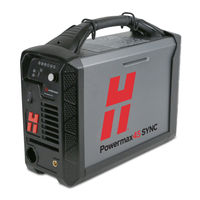
Table of Contents
Before You Begin
3
Electric Shock Can Kill
3
Install the Interface Cable
8
Shock Hazard
10
Avant de Commencer
15
Outils et Matériel Requis
16
Advertisement
Related Products
Hypertherm Powermax45 XP
Hypertherm powermax1250
Hypertherm powermax1650
Hypertherm Powermax1100
Hypertherm Powermax 85
Hypertherm powermax1000
Hypertherm powermax85
Hypertherm POWERMAX350
Hypertherm powermax900
Hypertherm powermax800
Hypertherm Categories
Welding System
Cutter
Flashlight
Industrial Equipment
Water Pump
More Hypertherm Manuals
Login
Sign In
OR
Sign in with Facebook
Sign in with Google
Upload manual
Upload from disk
Upload from URL