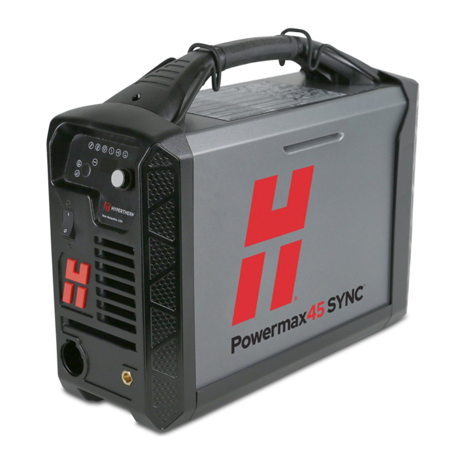
Hypertherm Powermax45 SYNC Manual
- Service manual (218 pages) ,
- Operator's manual (122 pages) ,
- Getting started manual (72 pages)
Advertisement
In the box

- Documentation
- SmartSYNC ® cartridge
- 15° or 75° hand torch with lead or machine torch with lead
- Work clamp with work lead
- Region-specific gas inlet fitting
- Power cord
- Remote-start pendant (optional - mechanized configurations only)
Set up the system
Step 1 - Connect to power
 NOTICE
The system must be correctly grounded. Refer to the Safety and Compliance Manual (80669C) for grounding requirements available at www.hypertherm.com/docs.
Voltage configurations
To operate the plasma power supply at full output as rated, your electrical service must be sufficient for your system. Refer to the table below for the maximum rated output for several typical input voltages.
| Unit | Input voltage (functional range) | Phase | Input current at rated output | Input current at rated arc stretch | Fuse* |
| CSA / CE / CCC | 200 V - 240 V | 1-phase | 33 A - 40 A | 36 A - 44 A | 50 A |
| CSA | 208 V | 1-phase | 37 A | 43 A | 50 A |
| CE / CCC | 230 V / 220 V | 1-phase | 34 A / 35 A | 37 A / 39 A | 50 A |
| CE / CCC | 400 V / 380 V | 3-phase | 12 A / 13 A | 15 A - 20 A | 20 A |
| CSA | 480 V | 3-phase | 10 A | 12 A - 17 A | 20 A |
*Hypertherm recommends that you use time-delay fuses.
Prepare the power cord
All plasma power supplies include power cords as shown here:
| Unit | Input Voltage (Functional Range) | Phase | Power cord |
| CSA | 200 V - 240 V | 1-phase | 10 AWG 3-wire Power plug included |
| CSA | 480 V | 3-phase | 14 AWG 4-wire power cord Power plug not included |
| CE / CCC | 100 V - 240 V | 1-phase | 6mm2 3-wire H07RN-F Power plug not included |
| CE / CCC | 380 V - 400 V | 3-phase | 2.5 mm2 4-wire H07RN-F Power plug not included |
Step 2 - Connect the gas supply

- CSA: Tighten the 1/4 NPT fitting to 11 N·m (100 lbf in).
- CE/CCC: Tighten the G-1/4 BSPP adapter to 10 N·m (90 lbf in).
- Use an inert gas hose with an internal diameter of 10 mm (3/8 in.) or more.
Gas requirements
- Use clean, moisture-free air and gas.
- Use a high-pressure regulator with shop-compressed gas or cylinder-compressed gas.
- For optimum system performance, make sure that the gas inlet flow rates meet these requirements:
- Cutting - 212 slpm (450 scfh) at a minimum 5.9 bar (85 psi).
- Gouging - 212 slpm (450 scfh) at a minimum 4.8 bar (70 psi).


EXPLOSION HAZARD
The filter bowl in the plasma power supply can explode if the gas pressure is more than 9.3 bar (135 psi). Never use more than the maximum gas pressure of 9.3 bar (135 psi).
Operate the system
Step 1 – Connect the torch lead
Push the connector into the receptacle on the front of the plasma power supply. The connector makes a click when it fully engages.

Step 2 – Connect the work lead and work clamp
Align the key on the connector with the opening in the receptacle. Push the connector into the receptacle.

Turn the connector clockwise approximately 1/4 turn until the connector is fully engaged and in the locked position.
Step 3 - Choose a cartridge
Standard hand cutting cartridges (428927): for the widest range of hand cutting and piercing applications. |
FineCut® hand cutting cartridges (428928): for a narrower kerf on thin mild steel and stainless steel up to 3 mm (10 gauge). |
Maximum Removal gouging cartridges (428932): for aggressive metal removal, deep gouge contours, and extreme metal washing . . |
FineCut mechanized cutting cartridge (428925): for use on machine torches to get a narrower kerf on thin mild steel and stainless steel up to 3 mm (10 gauge). Ideal for fine detail cutting. |
Standard mechanized cutting cartridges (428926): for use on machine torches for the widest range of mechanized cutting applications. |
Step 4 – Install the cartridge
Lock the torch before installing the cartridge. This prevents the torch from firing, even if the plasma power supply is ON.

Step 5 – Set the power switch to ON (I)
")
Step 6 - Unlock and fire the torch
- Move the torch lock switch to the green unlocked position.
![]()
After you unlock the torch, the system automatically goes to Cut mode or Gouge mode![]() , sets the system amperage
, sets the system amperage ![]() and sets the gas pressure for the cartridge you installed on the torch.
and sets the gas pressure for the cartridge you installed on the torch.

- Pull the torch trigger one time to get the warning puffs of air.
The plasma power supply makes a pressure release sound with each puff of air and the torch LED changes to green.


- Pull the torch trigger again to fire a plasma arc.
![information]() A pilot arc occurs when the torch is fired but the plasma arc is not in contact with the workpiece. Frequent pilot arcs cause the nozzle in the cartridge to wear more quickly.
A pilot arc occurs when the torch is fired but the plasma arc is not in contact with the workpiece. Frequent pilot arcs cause the nozzle in the cartridge to wear more quickly.
![]()

Adjust the output amperage if necessary
The output amperage is set automatically. If necessary, you can change it using the amperage adjustment button  on the SmartSYNC hand torch or the adjustment knob
  on the plasma power supply.
Unlock the torch before you change the amperage setting.

Use the SmartSYNC hand torch
The SmartSYNC hand torch shows you when the torch is ready to cut. It also shows you when you are in Cut mode or Gouge mode.
Torch status

Cut, pierce, and gouge metal
Cut
- Start at the edge of the workpiece
![]() .
.
![]()
- Fire the torch
![]() . Stay at the edge until the plasma arc cuts through the workpiece.
. Stay at the edge until the plasma arc cuts through the workpiece.
![]()
- Drag the torch lightly across the workpiece
![]() . Keep a stable pace. No standoff is required.
. Keep a stable pace. No standoff is required.
![]()
 .
.
 . Stay at the edge until the plasma arc cuts through the workpiece.
 . Keep a stable pace. No standoff is required.
Rolling pierce
- Hold the torch at an approximate 30° angle. Put the tip of the torch on the workpiece.
![]()
- Pull the trigger to start the plasma arc
![]() .
.
![]()
Tilt the torch up![]()
![]()
until it is at a 90° angle to the workpiece![]() .
.
![]()
- Hold the torch in position until the plasma arc pierces fully through the workpiece.

 .
.


 .
.
Gouge
- Hold the torch at an approximate 40° – 45° angle with the torch tip 6 mm – 12 mm (1/4 in. – 1/2 in.) from the workpiece
![]() .
.
![]()
- Pull the trigger to get a pilot arc. Transfer the arc to the workpiece.
![]()
![]()
- Stretch the plasma arc to 25 mm – 32 mm (1 in. – 1-1/4 in.).
As you gouge![]() , change the position of the torch to get the gouge contour that you want.
, change the position of the torch to get the gouge contour that you want.
![]()


Troubleshoot common problems
Identify when to install a new cartridge
The best indication of when to install a new cartridge is when the cut quality is no longer satisfactory.
The following signs can be indications that a cartridge is near or at end-of-life:
- Examine the nozzle hole. A nozzle hole in good condition is circular. If the nozzle hole is not circular, replace the cartridge.
- As a cartridge wears, unwanted material can collect inside the cartridge and cause faults to occur. In some conditions, you can remove this material by carefully shaking the cartridge.

- Examine the crown
![]() . The crown is the square copper piece inside of the cartridge. Push down on the crown and then release it.
. The crown is the square copper piece inside of the cartridge. Push down on the crown and then release it.

- A crown in good condition goes back to its start position. If the crown stays in the down position, carefully shake the cartridge. If the crown continues to stay in the down position, replace the cartridge.


Identify problems with cut quality - mild steel
Optimal cut quality
| What to look for |
| Lag lines with an angle of 10° – 15° |
| Minimal dross |
| Square edges |
| No splatter |
| No discolorations |
 |
Too much of a bevel angle
| Possible Cause | Solution |
| Torch is not at a 90° angle to the workpiece | Align the torch at a 90° angle to the workpiece |
| Amperage is too low | Increase the amperage |
| Speed is too fast | Decrease the speed |
| Worn cartridge | Install a new cartridge |
 | |
Hardened dross
| Possible Cause | Solution |
| Amperage is too low | Increase the amperage |
| Speed is too slow | Increase the speed |
 | |
Identify common system problems
Many common problems with Powermax® systems can be solved by doing the following checks.
 For a complete list of solutions to problems like these, refer to the Powermax45 SYNC Operator Manual (811470).
Examine the cartridge:
- Is the cartridge installed correctly?
- Is the cartridge worn or damaged?
Examine the gas supply line:
- Are there any signs of contamination from oil, water, or dirt? It is extremely important to keep a clean, dry gas line.
- Are there any signs of leaks?
- Are any of the hoses twisted or kinked?
- Are you able to keep sufficient gas pressure while cutting?
Do a gas test if needed. Refer to "Do a gas test".
Examine the power cord:
- Are the power cord wires connected correctly and fully tightened in the plasma power supply and in the power plug or line-disconnect box?
- Is the ground wire connected correctly?
- Is the power plug correct for the power cord?
Examine the work lead and work clamp:
- Is the work lead connected correctly to the plasma power supply?
- Is the work clamp connected to the workpiece that you are cutting? Does it have good contact with the metal?
Examine the torch and torch lead:
- Is the torch lead twisted or kinked?
- Is the O-ring on the torch head dry, cracked, or damaged?
In some conditions, restarting the plasma power supply can remove a fault condition.
Do a gas test
Do a gas test to see if sufficient gas pressure is exiting the torch. The gas test lets you see the actual gas pressure of the plasma power supply so that you can compare it to the inlet set pressure.
CHANCE OF BURNS AND CUTS
Point the torch away from you before doing a gas test. Always keep hands, clothes, and objects clear of the torch tip. Never point the torch toward yourself or others.
Enter gas test mode
- Unlock the torch and then pull the torch trigger one time to get the warning puffs of air.
- Press and hold the Mode button
![]() for approximately five seconds.
for approximately five seconds. - Release the Mode button when the display
![]() shows P.C. P.C. indicates pressure check.
shows P.C. P.C. indicates pressure check.

The set pressure![]() flashes on the display before the actual output gas pressure
flashes on the display before the actual output gas pressure ![]() shows. Make note of the set pressure so that you can compare it to the actual pressure.
shows. Make note of the set pressure so that you can compare it to the actual pressure.

 for approximately five seconds.
 shows P.C. P.C. indicates pressure check.
 flashes on the display before the actual output gas pressure
  shows. Make note of the set pressure so that you can compare it to the actual pressure.
When gas test mode is active
- Air flows continuously from the torch tip
![]() .
. - The AMPS LED
![]() remains off.
remains off. - The display shows the output gas pressure
![]()
 .
.
 .
.Exit gas test mode
Do one of the following actions to exit gas test mode:
- Press the Mode
![]() button.
button. - Turn the adjustment knob in any direction
![]() .
.


After the system exits gas test mode:
- The display shows the cutting current (amperage).
- The AMPS LED illuminates.
Identify common fault conditions
Refer to the Powermax45 SYNC Operator Manual (811470) for a complete list of fault codes and conditions.

USA
603-643-3441 Tel (Main Office)
603-643-5352 Fax (All Departments)
info@hypertherm.com (Main Office)
800-643-9878 Tel (Technical Service)
technical.service@hypertherm.com (Technical Service)
800-737-2978 Tel (Customer Service)
customer.service@hypertherm.com (Customer Service)
Documents / Resources
References
Download manual
Here you can download full pdf version of manual, it may contain additional safety instructions, warranty information, FCC rules, etc.
Advertisement


Need help?
Do you have a question about the Powermax45 SYNC and is the answer not in the manual?
Questions and answers