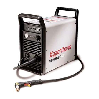
Sign In
Upload
Manuals
Brands
Hypertherm Manuals
Welding System
powermax900
Hypertherm powermax900 Manuals
Manuals and User Guides for Hypertherm powermax900. We have
4
Hypertherm powermax900 manuals available for free PDF download: Service Manual, Operator's Manual, Installation Manual, Field Service Bulletin
Hypertherm powermax900 Service Manual (107 pages)
Plasma Arc Cutting System
Brand:
Hypertherm
| Category:
Welding System
| Size: 2.68 MB
Table of Contents
English
6
Electromagnetic Compatibility
4
Warranty
5
Table of Contents
6
Safety
10
Section 1 Safety
10
Recognize Safety Information
11
Follow Safety Instructions
11
Cutting Can Cause Fire or Explosion
11
Electric Shock Can Kill
12
Cutting Can Produce Toxic Fumes
12
Arc Rays Can Burn Eyes and Skin
13
Plasma Arc Can Cause Injury and Burns
13
Grounding Safety
13
Compressed Gas Equipment Safety
14
Additional Safety Information
14
Noise Can Damage Hearing
14
Gas Cylinders Can Explode if Damaged
14
Pacemaker and Hearing Aid Operation
14
Français
16
Section 1A Sécurité
16
Danger Avertissement Précaution
17
Identifier Les Consignes de Sécurité
17
Le Coupage Peut Provoquer un Incendie Ou Une Explosion
17
Suivre Les Instructions de Sécurité
17
Le Coupage Peut Produire des Vapeurs Toxiques
18
Les Chocs Électriques Peuvent Être Fatals
18
L'arc Plasma Peut Provoquer des Blessures Ou des Brûlures
19
Les Rayons de L'arc Peuvent Brûler Les Yeux Et la Peau
19
Mise À la Masse Et À la Terre
19
Les Bouteilles de Gaz Comprimé Peuvent Exploser en Cas de Dommages
20
Pacemakers Et Prothèses Auditives
20
Sécurité des Bouteilles de Gaz Comprimé
20
Specifications
22
Section 2 SPECIFICATIONS
22
Introduction
23
Specifications
23
Specifications
24
Power Supply
24
Pac125 Torches
25
PAC125T Hand Torch Assembly
25
PAC125M Machine Torch Assembly
25
S Mark
26
Setup Specifications
26
Power Cord Plugs
26
Power Cords
26
208/240/480/600V Power Supplies
26
200/230/400V Power Supplies
26
Power Requirements
27
Service Manual
27
Section 3 MAINTENANCE
28
Introduction
29
Routine Maintenance
29
Bowl Draining/Filter Element Cleaning
29
Removal, Cleaning and Replacement of the Cooling Air Filter
30
Controls and Indicators
31
Theory of Operation
32
General
32
Functional Description
33
Sequence of Operation
34
Troubleshooting
35
Test Equipment
35
Troubleshooting Procedures
35
Visual Inspection - External
35
Visual Inspection - Internal
36
Resistance Checks
37
Voltage Checks
45
Power Board Test Points
49
Power Board
49
Control Board
51
Control Board Leds
51
Pac125T Torch Parts Removal and Replacement
53
Torch Main Body Removal and Replacement
53
Torch Switch Removal and Replacement
54
Pac125M Torch Parts Removal and Replacement
55
Removal
55
Replacement
55
Quick Disconnect O-Ring Removal and Replacement
57
Parts List - 208/240/480V
58
Power Supply - 208/240/480V
59
Front
59
Power Supply - 208/240/480V Front
59
Top and Right Side
61
Bottom and Left Side
63
Rear
65
Powermax900 Field Upgrade Kits and Optional Parts
67
Power Supplies - 208/240/480V
67
Recommended Spare Parts - Powermax900- 208/240/480V
68
Parts List - 200/230/400V
70
Power Supply - 200/230/400V
71
Front
71
Top and Right Side
73
Bottom and Left Side
75
Rear
77
Powermax900 Field Upgrade Kits and Optional Parts
79
Power Supplies - 200/230/400V
79
Recommended Spare Parts - Powermax900- 200/230/400V
80
Power Supply - 400V Ce
83
Front
83
Top and Right Side
85
Bottom and Left Side
87
Rear
89
Powermax900 Field Upgrade Kits and Optional Parts
91
Power Supplies - 400V Ce, 3F, 50 Hz
91
Recommended Spare Parts - Powermax900 400V Ce
92
Section 7 PARTS LIST - TORCHES and CONSUMABLES
94
PAC125T Torch Assembly and 25 Ft (7.6 M) Lead - 083066
95
PAC125T Torch Assembly and 50 Ft (15.2 M) Lead - 083067
95
PAC125M Torch Assembly and 14 Ft (4.3 M) Lead - 083069 W/Pigtail, 083073 no Pigtail
96
PAC125M Torch Assembly and 25 Ft (7.6 M) Lead - 083068 W/Pigtail, 083072 no Pigtail
96
PAC125M Torch Assembly and 35 Ft (10.6 M) Lead - 083070 W/Pigtail, 083074 no Pigtail
96
PAC125M Torch Assembly and 50 Ft (15.2 M) Lead - 083071 W/Pigtail, 083075 no Pigtail
96
Consumable Parts Kits
97
Consumable Spare Parts Kit - CE (128289)
97
Consumable Configurations
98
Section 8 Wiring Diagrams
100
Appendix A AERATION MANIFOLD for PLASMA CUTTING ALUMINUM
104
Introduction
104
Making an Aeration Manifold - Figure
104
Appendixa
104
Appendix B
105
Standards Index
105
Appendixb
105
Appendix C
106
Machine Interface Specifications
106
Appendixc
106
Advertisement
Hypertherm powermax900 Operator's Manual (73 pages)
plasma arc cutting system
Brand:
Hypertherm
| Category:
Welding System
| Size: 1.59 MB
Table of Contents
English
6
Electromagnetic Compatibility
4
Warranty
5
Table of Contents
6
Recognize Safety Information
11
Follow Safety Instructions
11
Cutting Can Cause Fire or Explosion
11
Electric Shock Can Kill
12
Cutting Can Produce Toxic Fumes
12
Arc Rays Can Burn Eyes and Skin
13
Compressed Gas Equipment Safety
14
Additional Safety Information
14
Noise Can Damage Hearing
14
Gas Cylinders Can Explode if Damaged
14
Pacemaker and Hearing Aid Operation
14
Français
16
SECTION 1A SÉCURITÉ
16
Danger Avertissement Précaution
17
Identifier Les Consignes de Sécurité
17
Le Coupage Peut Provoquer un Incendie Ou Une Explosion
17
Suivre Les Instructions de Sécurité
17
Le Coupage Peut Produire des Vapeurs Toxiques
18
LES CHOCS ÉLECTRIQUES PEUVENT Être Fatals
18
L'arc Plasma Peut Provoquer des Blessures Ou des Brûlures
19
Les Rayons de L'arc Peuvent Brûler Les Yeux Et la Peau
19
Mise À la Masse Et À la Terre
19
Le Bruit Peut Provoquer des Problèmes Auditifs
20
Les Bouteilles de Gaz Comprimé Peuvent Exploser en Cas de Dommages
20
Pacemakers Et Prothèses Auditives
20
Sécurité des Bouteilles de Gaz Comprimé
20
Specifications
22
Section 2 Specifications
22
Introduction
23
Figure 2-1 Powermax900 Hand Plasma Cutting System
23
Specifications
23
Specifications
24
Power Supply
24
Figure 2-2 Powermax900 Power Supply with Dimensions
24
Pac125 Torches
25
PAC125T Hand Torch Assembly
25
PAC125M Machine Torch Assembly
25
Figure 2-3 PAC125T Torch with Dimensions
25
Figure 2-4 PAC125M Torch with Dimensions
25
S Mark
26
Iec Symbols Used
27
Section 3 Setup
28
Setup
28
Claims
29
Upon Receipt
29
Figure 3-1 Powermax900 Power Supply Hoisting Setup
30
Hoisting Requirements
30
Figure 3-2 Rear Panel
31
Voltage Configurations
31
Figure 3-3 200V or 208V Configuration
32
Figure 3-4 230V or 240V Configuration
32
Figure 3-5 400V or 480V Configuration
32
Power Cord Plugs
33
Power Cords
33
208/240/480/600V Power Supplies
33
200/230/400V Power Supplies
33
Figure 3-6 Power Cord Preparation
33
Figure 3-6A Power Cord Preparation - CE
33
Single-Phase and Three-Phase Power Configurations
34
Single-Phase
34
Three-Phase - Non-CE
34
Figure 3-7 Single-Phase Power
34
Figure 3-8 Three-Phase Power Non-CE
34
Power Requirements
35
Line Voltage Disconnect Box
35
Figure 3-9 Three-Phase CE Power
35
Three-Phase - CE
35
Three-Phase CE
35
Figure 3-10 Proper Work Clamp Connection
36
Grounding Requirements
36
Work Cable and Clamp
36
Gas Supply Requirements
37
Air Supply Quality
37
Additional Air Filtration
37
Nitrogen Quality
37
Figure 3-11 Recommended Three-Stage Air Filtration System
37
Figure 3-12 Rear Panel, Gas Supply Connection to Filter
38
PAC125M ON/OFF Pendant Connection
39
PAC125M Torch ON/OFF Switch Connection Data
39
PAC125M Torch Alignment
39
Figure 3-13 ON/OFF Pendant Connection
39
Gas Supply Connection
38
Torch Lead Connection
38
Figure 3-14 Aligning the Machine Torch with Square
40
Figure 3-15 Machine Interface Cable and Signals
40
Arc Voltage
41
Figure 3-17 Machine Interface Board Connections for Arc Voltage
41
Machine Interface with Pac125M
40
Figure 3-16 Feeding Arc Voltage Cable to Machine Interface Board
41
Operation
42
Section 4 Operation
42
Controls and Indicators
43
Figure 4-1 Powermax900 Controls and Indicators
43
Figure 4-2 Powermax900 Operating Indicators and Adjustments
44
Pilot Arc Controller Option
45
Figure 4-3 Proper Work Clamp Connection
45
PAC125T Safety Trigger Operation
46
Figure 4-4 PAC125T Torch Safety Trigger Operation
46
Operating Instructions
44
Operating Tips
47
Changing Consumable Parts
47
Figure 4-5 Consumables
48
Cutting
49
Figure 4-6 Starting a Cut
49
Figure 4-7 Cutting a Circle
50
Figure 4-8 Dragging the Torch
50
Figure 4-9 Piercing
51
Piercing
51
Figure 4-10 Gouging
52
Gouging
52
Cut Chart - 55A Standard Consumables
53
Cut Chart - 35A Consumables
54
Common Cutting Faults
55
Maintenance/Parts
56
Section 5 Maintenance/Parts
56
Introduction
57
Routine Maintenance
57
Bowl Draining and Filter Element Cleaning
57
Figure 5-1 Filter Assembly
57
Figure 5-2 Air Filter Removal
58
Removal, Cleaning and Replacement of the Cooling Air Filter
58
Basic Troubleshooting
59
Technical Questions
62
Parts
63
Consumable Parts Kits
63
Consumable Parts Kit - CE (128289)
63
Hand Consumable Parts Kit
63
Machine Consumable Parts Kit
63
Consumable Parts Kit - CE
63
Consumable Configurations
64
Figure 5-3 Shielded Consumable Configurations
64
Figure 5-4 Unshielded Consumable Configurations
64
Figure 5-5 PAC125T Torch Assembly and Leads
65
PAC125T Torch Assembly
65
PAC125T Torch Assembly and 25 Ft (7.6 M) Lead - 083066
65
PAC125T Torch Assembly and 50 Ft (15.2 M) Lead - 083067
65
Figure 5-6 PAC125M Torch Assembly and Leads
66
PAC125M Torch Assembly and 14 Ft (4.3 M) Lead - 083069 W/Pigtail, 083073 no Pigtail
66
PAC125M Torch Assembly and 25 Ft (7.6 M) Lead - 083068 W/Pigtail, 083072 no Pigtail
66
PAC125M Torch Assembly and 35 Ft (10.6 M) Lead - 083070 W/Pigtail, 083074 no Pigtail
66
PAC125M Torch Assembly and 50 Ft (15.2 M) Lead - 083071 W/Pigtail, 083075 no Pigtail
66
Power Supplies - 200/230/400V, 1F/3F, 50/60 Hz
67
Power Supplies - 208/240/480V, 1F/3F, 60 Hz
67
Power Supplies - 400V CE
67
Powermax900 Field Upgrade Kits and Optional Parts
67
Power Supplies - 400V Ce, 3F, 50 Hz
68
Changing Fuses
70
Figure A-1 F1 and F2 Fuse Location
70
Standards Index
71
Aeration Manifold
72
Hypertherm powermax900 Installation Manual (21 pages)
Brand:
Hypertherm
| Category:
Welding System
| Size: 0.61 MB
Table of Contents
Introduction
5
Table of Contents
6
Installation
7
Installation of Wheels and Casters to Transformer Case
9
Wheel Installation
9
Caster Installation
9
Attaching Power Supply Bracket to Powermax900 Chassis
11
Attaching 600V Transformer Case Assembly to Powermax900 Chassis
13
Switching Voltage Configuration to 480V
14
Hooking up the Three-Phase Transformer Secondary Power Cord from 600V Transformer Case Assembly to Powermax900
15
Choosing Plug, Power Cord and Line Disconnect Box Fuse
16
Power Cord Plug
16
Power Cord - 600V
16
Line Voltage Disconnect Box and Fuses
16
Parts List
18
Advertisement
Hypertherm powermax900 Field Service Bulletin (5 pages)
Wheel Kit Installation
Brand:
Hypertherm
| Category:
Industrial Equipment
| Size: 0.45 MB
Advertisement
Related Products
Hypertherm powermax1650
Hypertherm Powermax125
Hypertherm Powermax1100
Hypertherm Powermax 85
Hypertherm Powermax30 AIR
Hypertherm powermax1000
Hypertherm powermax65
Hypertherm powermax85
Hypertherm powermax600
Hypertherm Powermax105
Hypertherm Categories
Welding System
Cutter
Flashlight
Industrial Equipment
Controller
More Hypertherm Manuals
Login
Sign In
OR
Sign in with Facebook
Sign in with Google
Upload manual
Upload from disk
Upload from URL