HindlePower AT30 SERIES Manuals
Manuals and User Guides for HindlePower AT30 SERIES. We have 3 HindlePower AT30 SERIES manuals available for free PDF download: Operating And Service Instructions, Operating Instructions Manual, Operating Instruction
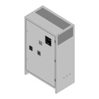
HindlePower AT30 SERIES Operating And Service Instructions (108 pages)
MICROPROCESSOR-CONTROLLED THREE PHASE INPUT FLOAT BATTERY CHARGER
Brand: HindlePower
|
Category: Battery Charger
|
Size: 1 MB
Table of Contents
Advertisement
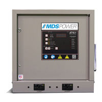
HindlePower AT30 SERIES Operating Instructions Manual (44 pages)
MICROPROCESSOR-CONTROLLED FLOAT BATTERY CHARGER COMMUNICATIONS MODULE
Brand: HindlePower
|
Category: Network Hardware
|
Size: 0 MB
Table of Contents
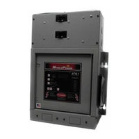
HindlePower AT30 SERIES Operating Instruction (9 pages)
microprocessor-controlled float battery chargers
Brand: HindlePower
|
Category: Battery Charger
|
Size: 0 MB
Table of Contents
Advertisement