Advertisement
JD5003-00
USING THE OPTIONAL TEMPERATURE COMPENSATION FEATURE
SCOPE
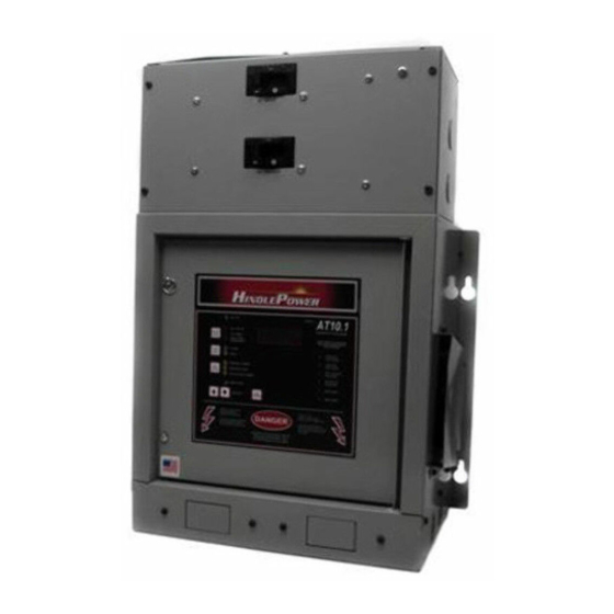
all single phase AT10.1 and all three phase AT30 microprocessor-controlled float battery chargers
SUMMARY
The AT Series battery charger can use an optional battery sensor (A10) to compensate dc output voltage for
changes in temperature. This option (manufacturer's p/n EJ5033-##), also referred to as "TempCo", consists
of a probe (or "puck") and an interconnection signal cable.
TEMPERATURE EFFECTS ON STORAGE BATTERIES
Storage batteries used in stationary applications are normally charged at a constant "float" voltage. The float
current depends on electro-chemical processes in the battery that vary with battery temperature. This causes
the float current to change as the temperature changes. This is true especially for the two battery types most
commonly used in industry (lead-acid and nickel-cadmium).
When storage batteries are charged at constant voltage, float current increases with increases in ambient
temperature. For a 10 °C increase in temperature, the float current approximately doubles (the change may be
smaller for a nickel-cadmium battery). Expressed differently, float charge voltage required to maintain a
constant float current decreases as temperature increases. Thus, we say that the battery float voltage has a
negative temperature coefficient. In normal float operation, the float voltage is chosen so that the float current
exactly compensates for internal self-discharge. Maintaining the balance between float current and self-
discharge is an important element in realizing maximum battery life.
The AT series charger normally has a constant dc output "float" voltage. If the charger is connected to a
battery that sees wide temperature fluctuations, the average float current may not be the optimum value. The
AT charger can use an optional temperature probe, mounted on or near the battery, to monitor the battery
temperature. The charger control circuit uses the information from the temperature probe to change the float
voltage as temperature varies, with the goal of maintaining the float current at the correct value.
WHEN TO USE TEMPERATURE COMPENSATION
If your battery is installed in a temperature-controlled room, you probably do not need a temperature-
compensated battery charger, although you should adjust the float voltage correctly for the temperature in the
battery room. However, you might consider adding temperature compensation to the charger if you have any
of the following conditions:
If the battery is in a temperature-controlled environment, but there is a risk of failure or
disconnection of the environmental controls (e.g. air conditioning).
If the battery is a Valve-Regulated Lead Acid (VRLA) type, and the battery room may see
moderate temperature changes.
If the battery is in a non-temperature-controlled environment.
If a site requirement exists for SCADA system battery temperature monitoring. Refer to the AT
Series Communications Module Operating Instruction (JA0102-04). See DNP3 Level 2 Section
5.4.3 (Analog Input Point Index 9) or Modbus Section 6.3.3 (Input Register 30010) for details.
To order TempCo (option p/n EJ5033-0#) with a new AT Series charger, choose it from the list on the order
sheet, or specify it on your purchase order. To order it for field installation, order the TempCo field retrofit
kit suitable for your application from your sales representative. See also www.ATSeries.net.
INSTALLING TEMPERATURE COMPENSATION
A separate installation procedure (JA5015-00) is supplied with each TempCo kit. The procedure is the
same for all AT Series battery chargers, and whether you have a new charger or are installing TempCo into an
existing unit. In most cases, you may follow the steps outlined in the AT Series battery charger Operating
and Service Instructions, Section 1.11. The installation steps outlined in the AT30 manual are reprinted on
Page 5 of this application note (JD5003-00) for convenience. Substitute "AT10.1" for "AT30" as needed.
JD5003-00.Rev6.doc
AT10.1/AT30 Series Battery Charger
Page 1 of 8
Rev. 6 - Last Printed 10/31/2014 10:31:00 PM
Application Note
Advertisement
Table of Contents

Related Manuals for HindlePower AT10.1 series


Summary of Contents for HindlePower AT10.1 series
- Page 1 AT10.1/AT30 Series Battery Charger JD5003-00 Application Note USING THE OPTIONAL TEMPERATURE COMPENSATION FEATURE SCOPE all single phase AT10.1 and all three phase AT30 microprocessor-controlled float battery chargers SUMMARY The AT Series battery charger can use an optional battery sensor (A10) to compensate dc output voltage for changes in temperature.
- Page 2 AT10.1/AT30 Series Battery Charger JD5003-00 Application Note ADJUSTING FLOAT & EQUALIZE VOLTAGES WITH TEMPCO Before setting the float and equalize voltages with the remote TempCo probe installed, it is a good idea to verify that the front panel voltmeter is calibrated, as described in the Operating and Service Instructions, Section 2.3.7.
- Page 3 AT10.1/AT30 Series Battery Charger JD5003-00 Application Note Compensated (or firmware Version 6.52 or lower) This is the default setting from the factory, and the only operation available on older units. If Jumper J30 is set at the 2-3 position, the charger will operate using compensated voltages. The front panel meter will display a dc voltage value modified for battery temperature.
- Page 4 AT10.1/AT30 Series Battery Charger JD5003-00 Application Note The thermistor used in current production has a nominal value of 10K Ohms at 25°C, and is interfaced with the charger microcontroller by an analog circuit, using a 5Vdc power supply. The maximum power dissipation of the thermistor is 0.6mW, and occurs at 25°C, which minimizes self-heating effects (less than 0.4°K).
- Page 5 AT10.1/AT30 Series Battery Charger JD5003-00 Application Note INSTALLATION INSTRUCTIONS (reprinted from AT30 Operating and Service Instructions, Section 1.11, Page 20) The remote TempCo probe contains a temperature-dependent resistor in an epoxy module that you install near your battery. There are three (3) steps in installing the assembly: 1.
- Page 6 AT10.1/AT30 Series Battery Charger JD5003-00 Application Note Run the cable though a conduit if possible, but not through a conduit containing any power wiring. Route the other end to the probe at the battery and coil up excess cable. NOTICE If the standard (25ft / 7.6m) cable is not long enough, longer cable assemblies are available in lengths of 50, 100 &...
- Page 7 AT10.1/AT30 Series Battery Charger JD5003-00 Application Note 8. Check your work. Be sure that: All connections are secure. The shield is connected to ground at the charger end only (A1-J6). The cable is connected to the 2-position terminal block (TB8) on the Main Control PC Board (A1).
- Page 8 AT10.1/AT30 Series Battery Charger JD5003-00 Application Note Note the following: You should set the Float and Equalize voltages to the values recommended by your battery manufacturer for 77 °F (25 °C). When you enter the Edit Mode to adjust the Float or Equalize voltage (see Section 2.3.2), the front panel meter displays the 77 °F (25 °C) value for the Float or Equalize voltage, even if the battery is warmer or cooler than 77 °F (25 °C).
Need help?
Do you have a question about the AT10.1 series and is the answer not in the manual?
Questions and answers