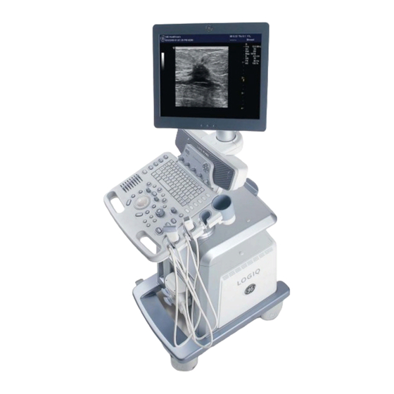
Sign In
Upload
Manuals
Brands
GE Manuals
Medical Equipment
LOGIQ P6
GE LOGIQ P6 Manuals
Manuals and User Guides for GE LOGIQ P6. We have
2
GE LOGIQ P6 manuals available for free PDF download: Service Manual, Technical Publication
GE LOGIQ P6 Service Manual (478 pages)
Brand:
GE
| Category:
Medical Equipment
| Size: 11.95 MB
Table of Contents
Table of Contents
13
Renewal Parts
20
CHAPTER 1 Introduction
23
CHAPTER 9 Renewal Parts
23
Overview
23
Purpose of Chapter 1
23
Purpose of Service Manual
23
Typical Users of the Basic Service Manual
24
LOGIQ™ P6/P6 Pro Models Covered by this Manual
24
Purpose of Operator Manual(S)
24
Important Conventions
25
Conventions Used in Book
25
Standard Hazard Icons
26
Product Icons
27
WEEE Label
29
Safety Considerations
34
Introduction
34
Human Safety
34
Mechanical Safety
34
Electrical Safety
35
Label Locations
36
Dangerous Procedure Warnings
38
Lockout/Tagout Requirements (for USA Only)
38
EMC, EMI, and ESD
39
Electromagnetic Compatibility (EMC)
39
CE Compliance
39
Electrostatic Discharge (ESD) Prevention
39
Customer Assistance
40
Contact Information
40
System Manufacturer
41
CHAPTER 2 Pre-Installation
43
Overview
43
Purpose of Chapter 2
43
General Console Requirements
44
Console Environmental Requirements
44
Electrical Requirements
45
EMI Limitations
47
Scan Probe Environmental Requirements
48
Facility Needs
49
Purchaser Responsibilities
49
Required Features
50
Desirable Features
51
Recommended and Alternate Ultrasound Room Layout
52
Networking Pre-Installation Requirements
53
Irection Evision Logiq™ P6/P6 Pro Ervice Anual
53
CHAPTER 3 Installation
55
Overview
55
Purpose of Chapter 3
55
Installation Reminders
55
Average Installation Time
56
Installation Warnings
56
Safety Reminders
57
Receiving and Unpacking the Equipment
58
Moving into Position
63
Adjusting System Clock
63
Product Locator Installation Card
63
Preparing for Installation
64
Verify Customer Order
64
Physical Inspection
64
EMI Protection
64
Completing the Installation
65
Power On/Boot up
65
Power Off/ Shutdown
67
Transducer Connection
68
System Configuration
69
System Specifications
69
Electrical Specifications
71
On-Board Optional Peripherals
71
External I/O Connector Panel
72
Video Specification
74
Setting VCR (Mitsubishi MD3000) USB Interface
75
Available Probes
76
Software/Option Configuration
76
Connectivity Installation Worksheet
77
Insite IP Address Configuration
78
Loading Base System Software
78
Warnings
78
Paperwork
79
Product Locator Installation
79
User Manual(S)
79
CHAPTER 4 Functional Checks
81
Overview
81
Purpose of Chapter 4
81
Required Equipment
81
General Procedure
82
Power On/Boot up
82
Power off / Shutdown
83
System Features
84
System B/M-Mode Checks
86
5245279, Revision
86
System CFM and PWD Checks
87
Basic Measurements
88
Probe/Connectors Usage
89
Using Cine
90
Image Management (QG)
90
Using the DVD-R
91
Backup and Restore Database, Preset Configurations and Images
95
ECG Check out
100
Software Configuration Checks
100
Peripheral Checks
101
Monitor Function Checks
102
17" LCDMON II Assy & LCD Panel with Filter Function Validation Procedure
102
17" OSD Key Assy Function Validation Procedure
103
Keyboard Function Checks
104
Main Keyboard Assy Function Validation Procedure
105
Sub Keyboard Assy Function Validation Procedure
107
Trackball Assy Validation
107
A/N Key Assy Validation
107
Freeze Key Validation
107
TGC Key Assy / TGC Knob Set Validation
108
Sub Keyboard Encoder Knob Set Validation
108
Mechanical Function Checks
109
Cover Parts Function Validation
109
Air Filter Set Function Validation Procedure
110
TGC Key Assy/Tgc Knob Set, Sub Keyboard Encoder Knob Set, Keycap Set, Main Keyboard Encoder Knob Set Function Validation Procedure
111
Cup Holder Function Validation Procedure
112
Front Caster/Rear Caster Function Validation Procedure
113
New Articulation Arm with Cover Function Validation Procedure
114
Board Function Checks
116
DTRX64II Assy Function Validation Procedure
117
CWD64 Assy Function Validation Procedure
118
SYSCONML Assy Function Validation Procedure
121
APS II Assy PCB Function Validation Procedure
122
SOM Function Validation Procedure
123
RFC Assy Function Validation Procedure
123
BP128 Assy Function Validation Procedure
124
Nest Fan Function Validation Procedure
125
Transbox/ Fan Function Validation Procedure
125
DTRX Cooler with Heatsink Function Validation Procedure
126
ACPC II Assy Set Function Validation Procedure
126
AP950 Transbox Assy Function Validation Procedure
127
Fuse Set Function Validation Procedure
127
ARPII Assy Function Validation Procedure
127
Site Log
128
Direction 5245279, Revision 3 Logiq™ P6/P6 Pro Service Manual
129
CHAPTER 5 Components and Functions (Theory)
131
Overview
131
Block Diagrams and Theory
132
LOGIQ™ P6/P6 Pro Block Diagram
133
Power Diagrams
139
Overview
139
TRANSBOX(AC Power, AP950)
139
APS II (LV Power & HV Power)
140
AC Power Outlet for Peripheral
141
Front End
141
Sysconml
142
Top Console
143
Keyboard
143
LOGIQ™ P6/P6 Pro Monitor
145
P6 ARP II (Rear Panel)
147
Input/Output Signals for Peripheral
148
Cable Connection
149
Overview
149
Internal Cable
149
Peripherals Connection
150
Filters
151
Fans
152
Service Platform
153
Introduction
153
Global Service User Interface (GSUI)
154
Iglobal Service User Interface (GSUI)
155
Service Home Page
156
Error Logs Tab
157
Diagnostics
159
Image Quality
160
Calibration
160
Configuration
161
Utilities
162
Replacement
163
Remote Software/Option Installation and Updates
164
RFS (Service for Request)
165
General
165
System Checkout Procedure
165
Sending RFS Procedure
168
Direction 5245279, Revision 3 Logiq™ P6/P6 Pro Service Manual
170
CHAPTER 6 Service Adjustment
175
Overview
175
Purpose of this Chapter 6
175
Regulatory
175
Monitor Adjustments
176
Brightness and Contrast
176
Monitor Arm Locking
177
Trackball Cleaning
178
CHAPTER 7 Diagnostics / Trouble Shooting
179
Overview
179
Purpose of Chapter 7
179
Collect Vital System Information
180
Gathering Trouble Data
180
Overview
180
Collect a Trouble Image with Logs
181
Check and Record the P2 Key Function
182
Screen Captures
182
Setting the P2 Key to Screen Capture
183
Capturing a Screen
184
Reset the P2 Key to Customer's Functionality
185
Diagnostics
186
Check and Record the P2 Key Function
187
Screen Captures
187
Setting the P2 Key to Screen Capture
188
Capturing a Screen
189
Reset the P2 Key to Customer's Functionality
190
Diagnostics
191
Common Diagnostics
192
Utilities
192
PC Diagnostics (Non-Interactive Tests)
193
PC Diagnostics (Interactive Tests)
197
FRU Test
198
DTRX64II Assy
203
LED Descriptions
203
P3RLY Assy (LOGIQ™ P6/P6 Pro PRO)
203
PI128 II Assy (LOGIQ™ P6/P6 Pro)
203
SYSCONML Assy
203
APS II Assy
204
System Does Not Power on / Boot up
205
Trouble Shooting Tree
205
System Does Not Boot
206
Noise in Image
209
Unable to Scan
210
Trackball
211
Monitor Troubleshooting
212
Purpose of Chapter 9
221
List of Abbreviations
426
Monitor
428
Keyboard
430
Covers
432
Nest
434
Body
436
Power
438
Cables
440
Options
443
Software
444
Probes
445
Peripherals
446
CHAPTER 10 Care and Maitenance
447
Overview
447
Periodic Maintenance Inspections
447
Purpose of Chapter 10
447
How Often Should Care & Maintenance Tasks be Performed
448
Keeping Records
448
Maintenance Task Schedule
448
Quality Assurance
448
Why Do Maintenance
448
Standard GE Tool Kit
450
Tools Required
450
Special Tools, Supplies and Equipment
452
Preliminary Checks
453
System Maintenance
453
Functional Checks (See also Chapter 4)
454
Cleaning
455
Input Power
455
Physical Inspection
456
Optional Diagnostic Checks
457
Probe Maintenance
457
Electrical Safety Tests
458
Safety Test Overview
458
GEMS Leakage Current Limits
459
Outlet Test - Wiring Arrangement - USA & Canada
460
Grounding Continuity
461
Chassis Leakage Current Test
463
Isolated Patient Lead (Source) Leakage-Lead to Ground
465
Isolated Patient Lead (Sink) Leakage-Isolation Test
468
Isolated Patient Lead (Source) Leakage-Lead to Lead
468
Advertisement
GE LOGIQ P6 Technical Publication (127 pages)
Ultrasound System
Brand:
GE
| Category:
Medical Equipment
| Size: 3.71 MB
Table of Contents
Table of Contents
21
Chapter 1 - Overview
25
Content in this Manual
26
Product Description
27
Overview of the Ultrasound System
27
Products Covered in this Manual
28
Chapter 2 - Safety Information
29
Overview
30
Contents in this Chapter
30
Important Conventions
31
Conventions Used in Book
31
Standard Hazard Icons
33
Product Icons
35
Label Icon Description
35
How to Lock the Operator Panel Prior to Transport
35
Safety Considerations
36
Introduction
36
Human Safety
36
Mechanical Safety
39
Electrical Safety
44
Label Locations
46
Product Labels
46
Dangerous Procedure Warnings
47
Warnings
47
Lockout/Tagout (LOTO)
48
LOTO Requirements
48
Returning Probes and Repair Parts
49
Requirements for Returning Parts
49
User Responsibility
49
Electromagnetic Compatibility (EMC)
50
What Is EMC
50
Compliance
50
Electrostatic Discharge (ESD) Prevention
51
Chapter 3 - Site Preparations
53
Overview
54
Contents in this Chapter
54
General Ultrasound System Requirements
55
Contents in this Section
55
Ultrasound System Environmental Requirements
55
Electrical Requirements
57
EMI Limitations
70
Probes Environmental Requirements
72
Time and Manpower Requirements
72
Facility Needs
73
Contents in this Section
73
Purchaser Responsibilities
73
Required Facility Needs
75
Desirable Features
77
Care and Maintenance
79
Contents in this Chapter
80
Chapter 4 - Care and Maintenance
81
Warnings
81
Why Do Maintenance
82
Keeping Records
82
Quality Assurance
82
Maintenance Task Schedule
83
How Often Should Maintenance Tasks be Performed
83
System Maintenance
84
Preliminary Checks
84
Functional Checks
85
Physical Inspection
87
Cleaning
89
Probe Maintenance
90
Using a Phantom
91
Phantoms
91
Electrical Safety Tests
92
Content in this Section
92
Uninterrupted Power Supply (UPS)
93
Safety Test Overview
94
Leakage Current Limits
97
Outlet Test - Wiring Arrangement - USA and Canada
101
Grounding Continuity
102
Chassis Leakage Current Test
103
Isolated Patient Lead (Source) Leakage-Lead to Ground
107
Isolated Patient Lead (Source) Leakage-Lead to Lead
109
Isolated Patient Lead (Sink) Leakage-Isolation Test
111
Probe (Source) Leakage Current Test
113
Isolated Probe (Sink) Leakage-Isolation Test
118
When There's too Much Leakage Current
122
AC/DC Fails
122
Chassis Fails
122
Probe Fails
123
Peripheral Fails
123
Still Fails
123
New Ultrasound System
123
ECG Fails
123
Ultrasound Equipment Quality Check (EQC and IQC)
124
Quality Checks
124
Advertisement
Related Products
GE LOGIQ P3 EXPERT
GE LOGIQ P6 Series
GE LOGIQ P5 Basic OB
GE LOGIQ P5 Premium OB
GE LOGIQ 5 PRO
GE LOGIQ 200 PRO Series
GE Logiq 500
GE LOGIQ 200
GE LOGIQ i
GE LOGIQ Book
GE Categories
Refrigerator
Ranges
Microwave Oven
Air Conditioner
Dishwasher
More GE Manuals
Login
Sign In
OR
Sign in with Facebook
Sign in with Google
Upload manual
Upload from disk
Upload from URL