Sign In
Upload
Manuals
Brands
GE Manuals
Medical Equipment
LOGIQ 5 PRO
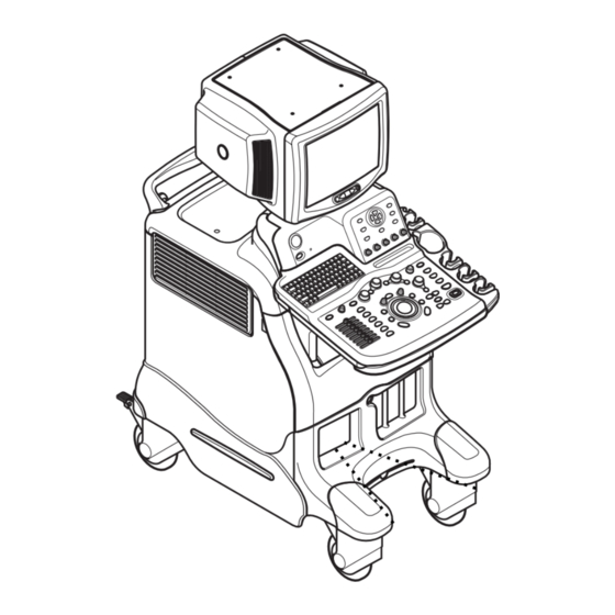
GE LOGIQ 5 PRO Manuals
Manuals and User Guides for GE LOGIQ 5 PRO. We have
1
GE LOGIQ 5 PRO manual available for free PDF download: Service Manual
GE LOGIQ 5 PRO Service Manual (463 pages)
Brand:
GE
| Category:
Medical Equipment
| Size: 24.84 MB
Table of Contents
Important Precautions
5
Table of Contents
11
Purpose of Service Manual
19
CHAPTER 1 Introduction
19
CHAPTER 4 Overview
19
Purpose of Chapter 1
19
Typical Users of the Basic Service Manual
20
LOGIQ™ 5 Models Covered by this Manual
20
Purpose of Operator Manual(S)
20
Conventions Used in Book
21
Important Conventions
21
Standard Hazard Icons
22
Product Icons
23
WEEE Label
25
Human Safety
30
Introduction
30
Mechanical Safety
30
Safety Considerations
30
Electrical Safety
31
Label Locations
32
Label Locations
33
Dangerous Procedure Warnings
35
Lockout/Tagout Requirements (for USA Only)
35
CE Compliance
36
Electromagnetic Compatibility
36
Electrostatic Discharge (ESD) Prevention
36
Customer Assistance
37
Contact Information
37
Pre-Installation
39
CHAPTER 2 Overview
39
Purpose of Chapter 2
39
General Console Requirements
40
Console Environmental Requirements
40
Electrical Requirements
40
Electrical Requirements
41
EMI Limitations
42
Scan Probe Environmental Requirements
43
Facility Needs
44
Required Features
44
Purchaser Responsibilities
44
Desirable Features
46
Recommended and Alternate Ultrasound Room Layout
47
Networking Pre-Installation Requirements
48
Installation
51
CHAPTER 3 Overview
51
Purpose of Chapter 3
51
Installation Reminders
52
Average Installation Time
52
Installation Warnings
52
Safety Reminders
53
Receiving and Unpacking the Equipment
54
Moving into Position
59
Adjusting System Clock
59
Product Locator Installation Card
59
Preparing for Installation
59
Verify Customer Order
59
Physical Inspection
60
EMI Protection
60
Completing the Installation
61
Power On/Boot up
61
Maintanance Mode for Service
63
Power Off/ Shutdown
64
Transducer Connection
65
System Configuration
66
System Specifications
66
Physical Dimensions
67
Electrical Specifications
68
On-Board Optional Peripherals
69
External I/O Connector Panel
69
External I/O Pin Outs
71
Video Specification
73
Available Probes
74
Software/Option Configuration
74
Connectivity Installation Worksheet
75
Paperwork
76
Product Locator Installation
76
Functional Checks
77
Overview
77
Scanner Power on
78
Circuit Breaker
79
Power off / Shutdown
80
Control Panel
81
Switch off the Scanner
81
System Features
81
Sub Menu Control Keys Menu Key Panel
82
Monitor Display Features
83
System B/M-Mode Checks
84
System CFM and PWD Checks
85
Basic Measurements
86
Activating the Probe
88
Connecting a Probe
88
Deactivating the Probe
88
Probe/Connectors Usage
88
Image Management (QG)
89
Using Cine
89
Using the CD-RW / MOD (Magneto-Optical Drive)
90
Backup and Restore Database, Preset Configurations and Images
92
Backup System Presets and Configurations
93
Archiving Images
95
ECG Check out
97
Application Turnover Checklist
98
Software Configuration Checks
98
Peripheral Checks
99
Site Log
100
Software Configuration Checks
101
Monitor Function Checks
102
CRT Assy Function Check Procedure
102
Monitor Cable Assy Function Check Procedure
102
Monitor S/W Assy Function Check Procedure
102
Rear Panel Assy Function Check Procedure
103
Keyboard Function Checks
104
Main Keyboard Assy Validation
104
OP Panel Encoder Assy Validation
108
TGC Knob Set Validation
108
A/N Key Assy Validation
108
Trackball Assy Validation
108
OP Panel LCD Assy Validation
109
OP Panel LCD Encoder Assy Validation
110
Menu Key Assy
111
Menu Encoder Assy
112
Speaker Assy Validation
113
Mechanical Function Checks
115
Cover Parts Function Validation
115
Task Lamp Assy Check
116
Keyboard Front Grip Check
116
Probe Holder Check
116
Gas Spring Assy Check
117
Front Caster/Rear Caster Check
117
Board Function Checks
121
RLY Assy Function Check Procedure
121
LMT Assy Function Check Procedure
122
PMP Assy Function Check Procedure
122
RDS Assy Function Check Procedure
123
ATD Assy Function Check Procedure
124
FECII Assy Function Check Procedure
125
CWDOP Assy Function Check Procedure
126
Backplane Assy Function Check Procedure
127
SIG Assy Function Check Procedure
127
DC FAN Assy Function Check Procedure
127
BEP Assy Function Check Procedure
128
HDD, Memory, CPU Diagnositc Test
128
VIC Assy Function Check Procedure
131
SMPS, HDD, ODD Assy Function Check Procedure
132
PC2IP Assy Function Check Procedure
133
AC Power Assy Function Check Procedure
134
LV Unit Function Check Procedure
134
JPC Function Check Procedure
134
Transformer Function Check Procedure
134
Components and Functions (Theory)
135
CHAPTER 5 Overview
135
Purpose of Chapter 5
135
Major Components Diagram
136
Block Diagram
137
Front End
139
RLY Block Diagram
140
LMT Block Diagram
141
Pmp
142
Atd
143
Rds
144
Fec
145
HV Power (Tx Power)
146
Backend Processor
148
Bep2
149
Bep3
150
Bt05 Bep3
151
VIC Card
152
VIC Card I/O Signal
153
Patient I/O (Option)
156
Top Console
157
Keyboard Block Diagram
157
Keyboard Signal I/O
158
Monitor
159
External I/O (Rear Panel)
160
Rear Panel Block Diagram
160
Input/Output Signals for Peripheral
161
Peripherals and Cable Connection
162
B/W Printer Cable Connection (Analog and Digital)
162
Cable Connection - Color Printer
163
Cable Connection - VCR
166
Interconnect Cabling
168
Power Diagrams
169
AC Power Assy Block Diagram
169
Overview
169
DC Power (Low Voltage)
170
AC Power Outlet for Peripheral
171
Air Flow Control
172
Air Flow Distribution
172
Filters
172
Fans
173
Service Platform
174
Introduction
174
Global Service User Interface (GSUI)
175
Service Home Page
176
Error Logs Tab
177
Diagnostics
181
Image Quality
182
Calibration
182
Utilities
183
Replacement
184
PM Page
184
Service Adjustments
185
Power Supply Adjustment
185
LV Unit Disassembly
185
CHAPTER 6 Overview
185
Purpose of this Chapter 6
185
Regulatory
185
Adjustments Procedures
187
Monitor Adjustments
188
Contrast and Brightness Adjustment
188
Diagnostics/Troubleshooting
191
Network Connectivity Troubleshooting
191
CHAPTER 7 Diagnostics/Troubleshooting
191
Overview
191
Purpose of Chapter 7
191
Gathering Trouble Data
192
Collect Vital System Information
192
Overview
192
Collect a Trouble Image with Logs
193
Screen Captures
195
Check and Record the P4 Key Function
195
Setting the P4 Key to Screen Capture
196
Capturing a Screen
197
Reset the P4 Key to Customer's Functionality
198
Global Service User Interface Diagnostic Screen
199
Common Diagnostics
200
Disruptive Mode
200
Utilities
200
PC Diagnostics (Interactive Tests)
205
CHAPTER 8 Replacement Procedures
207
Disassembly/Re-Assembly
207
Overview
207
Purpose of Chapter 8
207
Monitor Disassembly and Reassembly
208
CRT Assy (FRU No. 100)
208
Monitor Calibration
210
Monitor Cable Assy (FRU No. 101)
212
Monitor Cover Set (FRU No. 102)
214
Monitor S/W Assy (FRU No. 103)
216
Speaker Assy (FRU No. 104)
218
Task Lamp Assy (FRU No. 105)
220
Keyboard Block
222
Keyboard Assy (FRU No. 200)
222
Keyboard Front Grip (FRU No. 201)
225
Probe Holder (FRU No. 202)
227
ECG Cable Hook (FRU No. 203)
228
OP Panel Encoder Assy (FRU No. 204)
230
OP Panel TGC Assy (FRU No. 205)
233
TGC Knob Set (FRU No. 206)
235
OP Panel A/N Keyboard Assy (FRU No. 207)
236
OP Panel Trackball Assy (FRU No. 208)
239
OP Panel HUB Board Assy (FRU No. 209)
241
Direction 2380207, Revision 7 Logiq™ 5 Pro Service Manual
241
Manu Key Assy
243
Left Cover (FRU No. 300)
247
Right Cover (FRU No. 301)
249
Rear Cover (FRU No. 302)
251
Rear Door Cover (FRU No. 303)
253
Top Cover (FRU No. 304)
255
Front Base Cover (FRU No. 305)
257
Front Cover (FRU No. 306)
259
OP Side L Cover (FRU No. 307)
260
OP Side R Cover (FRU No. 308)
262
OP Rear Cover (FRU No. 309)
264
OP Bottom Cover (FRU No. 310)
266
OP Curtain Cover (FRU No. 311)
268
EMI Cover L (FRU No. 312)
270
EMI Cover R (FRU No. 313)
272
Side Cap (FRU No. 314)
274
Side Fringe (FRU No. 315)
276
Body Block
278
Rear Handle
278
Rear Handle (FRU No. 400)
279
Rear Panel Assy (FRU No. 401)
281
How to Check and Write the System Serial Number on EEPROM
284
Replace the EEPROM on the RDI Assy in the Rear Panel Assy
284
Front Caster (FRU No. 403)
287
Front Caster Removal
287
Rear Caster (FRU No. 404)
289
Bumper Set (FRU No. 405)
291
Air Filter Set (FRU No. 406)
293
PCB Boards
294
RLY Assy (FRU No. 500)
294
LMT Assy (FRU No. 501)
297
Backplane (FRU No. 502)
299
PCB Boards (FRU No. 503, 505~510)
301
DC Fan Assy(FRU No. 504)
304
BEP (Back End Processor) ASSY(FRU No. 600)
306
General Procedures of BEP Assy Disassembly
306
BEP Cable Connection with Console
309
System Functional Check
318
Advanced Menu
319
Check the Device Driver Configuration
328
Application S/W Install
344
VIC Assy
345
Removal of VIC Board
346
SMPS Assy, Hard Disk, CD R/W (FRU No. 601, 602, 603)
350
Connect HDD
354
Hard Disk Copy Procedure
354
Data Copy to New HDD
355
File Copy
355
Check the Patient Data
358
PC Block
306
Power Block
359
AC Power Assy (FRU No. 700)
359
LV Unit (FRU No. 701)
362
JPC Assy (FRU No. 702)
364
Transformer (FRU No. 703)
367
AC Power Box (FRU No. 704)
369
Fuse Set (FRU No. 705)
371
Manpower
371
Preparations
371
Tools
371
Software Loading Procedure
372
Software Loading Steering Guide
373
Before Starting Software Loading
374
Saving Connectivity
376
Image Management Guide
377
Operator Login Password Back-Up
377
Tools
377
Storing Images with more Resolution
379
Installing Base Software Load Image CD
383
Tools
390
USB Printer Checks (USB Printer User Only)
396
DMC Checks (DMC User Only)
398
Installig Application Software (R4.X.X)
400
Standard Confirmation & Functional Checks
402
Setting Computer Name
403
Functional Checks for Service Platform (Diagnostic Program)
404
Setting the VCR (if Necessary)
407
Full Backup / Restore Procedure
408
Restore Procedure
412
CHAPTER 9 Renewal Parts
413
Equipment Models Covered in this Chapter
414
Exploded Views and Parts Lists
415
Care & Maintenance
435
CHAPTER 10 Periodic Maintenance
435
Overview
435
Keeping Records
436
Maintenance Task Schedule
436
Quality Assurance
436
Customer Care Schedule
437
Special Tools, Supplies and Equipment
438
Preliminary Checks
439
Input Power
441
General Cleaning
441
Air Filter Cleaning
442
Physical Inspection
442
Optional Diagnostic Checks
443
Probe Maintenance
443
Basic Probe Care
443
Basic Probe Cleaning
443
Electrical Safety Tests
444
Using a Phantom
444
Safety Test Overview
444
GEMS Leakage Current Limits
445
Grounding Continuity
446
Outlet Test - Wiring Arrangement - USA & Canada
446
Meter Procedure
447
Chassis Leakage Current Test
448
Isolated Patient Lead (Source) Leakage–Lead to Ground
449
Isolated Patient Lead (Source) Leakage–Lead to Lead
450
Isolated Patient Lead (Sink) Leakage-Isolation Test
450
Testing Power Conditions
450
Data Sheet for ECG Leakage Current
452
Probe Leakage Current Test
453
No Meter Probe Adapter Procedure
454
Data Sheet for Transducer Source Leakage Current
455
Chassis Fails
456
Probe Fails
456
When There's too Much Leakage Current
456
Index
459
Advertisement
Advertisement
Related Products
GE Logiq 500
GE LOGIQ 5
GE LOGIQ 200
GE LOGIQ 100 PRO
GE LOGIQ i
GE LOGIQ Book
GE LOGIQ P6
GE LOGIQ e Vet
GE LOGIQ S8
GE LOGIQ E8
GE Categories
Refrigerator
Ranges
Microwave Oven
Air Conditioner
Dishwasher
More GE Manuals
Login
Sign In
OR
Sign in with Facebook
Sign in with Google
Upload manual
Upload from disk
Upload from URL