Sign In
Upload
Manuals
Brands
Fluke Manuals
Test Equipment
2635A
Fluke 2635A Manuals
Manuals and User Guides for Fluke 2635A. We have
1
Fluke 2635A manual available for free PDF download: User Manual
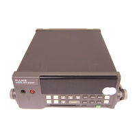
Fluke 2635A User Manual (268 pages)
Data Bucket
Brand:
Fluke
| Category:
Test Equipment
| Size: 1.56 MB
Table of Contents
Table of Contents
3
Preparation for Use
27
Introduction
31
Operating Modes
31
Chapter 1
31
Front Panel Operation
31
Memory Card Operation
31
Computer Operation
34
Printer Operation
34
Modem Operation
34
Measurement Capabilities
35
MX+B Scaling
35
Alarms
35
Totalizer Channel
35
Alarm Outputs and Digital I/O
35
Applications Software
35
Hydra Starter Package
36
Hydra Logger
36
Options and Accessories
36
Memory Card Reader
36
Connector Set, 2620A-100
36
Setting up the Instrument
37
Unpacking and Inspecting the Instrument
37
Adjusting the Handle
38
Connecting the Instrument to a Power Source
38
AC Operation
39
DC Operation
39
Input Channels
39
Measurement Connections
40
Using Shielded Wiring
40
Crosstalk
40
Universal Input Module Connections
40
Alarm Outputs Connections
43
DC Power
43
Alarm Outputs
43
External Trigger Input
43
Digital I/O Connections
44
Digital I/O
44
Totalizer Input
44
Controls and Indicators
45
Front Panel Controls
45
Front Panel Indicators
45
Front Panel Operations
51
Summary of Front Panel Operations
55
Configuring the Instrument for Operation
56
Chapter 2
56
Turning the Power on
56
Selecting a Channel
58
Configuring a Measurement Channel
58
Configuring a Channel to Measure DC Volts
59
Configuring a Channel to Measure AC Volts
60
Configuring a Channel to Measure Resistance
61
Configuring a Channel to Measure Frequency
62
Configuring a Channel to Measure Temperature
63
Thermocouples
63
Resistance-Temperature Detectors
63
Thermocouple Restrictions
63
Resistance Temperature Detectors Restrictions
63
Configuring a Channel off
66
Setting Operating Conditions
66
Setting the Scan Interval
67
Setting the Measurement Rate
68
Setting the Alarms
68
Alarm Indications While Scanning
68
Alarm Indications While Monitoring
69
Alarm Indications While Reviewing
69
Clearing Alarm Parameters from a Channel
69
Alarm Outputs for Channel 0 to 3 Using the Alarm Outputs Connector
69
Alarm Outputs for Channels 4 to 20 Using the Digital I/O Connector
69
Alarms and Autoprinting
70
Alarms and Monitor-Alarm Triggering
70
Alarms and MX+B Scaling
70
Setting the MX+B Scaling
73
Examples
73
Restrictions
73
Clearing MX+B Scaling from a Channel
73
Operating Modes
76
Using the Scan Mode
76
Memory Card as a Data Destination
76
Memory Card Formatting
76
Memory Card Capacity
76
Memory Card Files
76
Memory Card Exchange During Scanning
76
Memory Card Data Extraction
77
Memory Card Error Messages
78
Using the Monitor Mode
79
Using the Review Mode
80
Additional Features
81
Scan Triggering Options
81
External Trigger
81
Monitor-Alarm Trigger
81
Triggering Options and Memory Card Operation
81
Totalizer Operation
82
Digital Input/Output Lines
83
Setting Date and Time
84
Reading Instrument Software Versions
85
Returning to the Local Mode
85
Front Panel Key Lockout Options
86
Instrument Interfaces
86
Memory Card Interface
86
RS-232 Computer Interface
87
Using the RS-232 Computer Interface with a Printer
87
Using the RS-232 Computer Interface with a Modem
87
Memory Card Operations
89
Summary of Memory Card Operations
91
Chapter 3
91
Memory Card Files
91
Setup Files
92
Data Files
92
Memory Card Capacity
92
Memory Card Battery
93
Inserting and Removing the Memory Card
93
Inserting a Memory Card
93
Removing a Memory Card
93
Changing the Memory Card During Scanning
93
Setting the Memory Card Write-Protect Feature
93
Installing or Replacing the Memory Card Battery
93
Initializing a Memory Card
95
Recording Measurement Results During Scanning
96
Setup File Procedures
97
Using Setup Store
97
Using Setup Load
98
Using Setup Erase
99
Data File Procedures
100
Using Data Open
100
Using Data Erase
101
Setup and Data Files Directory
102
Setup and Data File Current Status
103
Memory Card File Operations to and from a PC
104
Computer Operations
105
Chapter 4
107
Summary of Computer Operations
107
Connecting the Instrument to a PC
107
Configuring the Instrument for Computer Operations
109
Configuring the PC for Computer Operations
110
Testing the Instrument/Pc RS-232 Interface
110
Testing the RS-232 Interface Using Terminal Emulation (Windows)
110
Testing the RS-232 Interface Using Terminal Emulation (Generic)
111
Testing the RS-232 Interface Using Gwbasic
113
Testing the RS-232 Interface Using Qbasic
114
Computer Interface Commands and Operation
116
How the Instrument Processes Input
116
Input Terminators
116
Input String Examples
117
Sending Numeric Values to the Instrument
117
How the Instrument Processes Output
117
Status Registers
118
Instrument Event Register (IER)
118
Standard Event Status Register (ESR)
120
Status Byte Register (STB)
121
Computer Interface Command Set
122
Xmodem File Transfers
122
Printer Operations
171
Chapter 5
173
Summary of Printer Operations
173
Connecting the Instrument to a Printer
173
Configuring for Printer Operations
175
Printing Measurement Data and Memory Card Directory
176
Problems
176
Printing Measurement Results During Scanning
176
Printing the Review Array
178
Printing the Directory of the Memory Card
179
Modem Operations
181
Chapter 6
183
Summary of Modem Operations
183
Connecting the Modem to a PC for Modem Configuration
184
Configuring the Instrument Modem for Modem Operations
184
Connecting the Modem to an Instrument
186
Configuring the Instrument for Modem Operations
187
Testing the RS-232/Modem Interface
188
Maintenance
189
Chapter 7
191
Introduction
191
Cleaning
191
Line Fuse
191
Selftest Diagnostics and Error Codes
192
Performance Tests
192
Accuracy Verification Test
195
Channel Integrity Test
196
Thermocouple Measurement Range Accuracy Test
197
Four-Terminal Resistance Test
198
Thermocouple Temperature Accuracy Test
198
Open Thermocouple Response Test
199
RTD Temperature Accuracy Test
201
RTD Temperature Accuracy Test (Using Decade Resistance Source)
201
RTD Temperature Accuracy Test (Using DIN/IEC 751 RTD)
202
Digital Input/Output Verification Tests
203
Digital Output Test
203
Digital Input Test
204
Totalizer Test
205
Totalizer Sensitivity Test
206
Dedicated Alarm Output Test
206
External Trigger Input Test
209
Calibration
209
Variations in the Display
210
Service
210
Appendices
211
A Specifications
213
Appendix
213
Specifications
213
B Crosstalk Considerations
231
Crosstalk Considerations
231
C Binary Upload of Logged Data
235
Binary Upload of Logged Data
235
RS-232 Cabling
243
8-Bit Binary-Coded-Decimal Table
251
E 8-Bit Binary-Coded-Decimal Table
252
Memory Card File Formats
253
G True RMS Measurements
261
True RMS Measurements
261
Advertisement
Advertisement
Related Products
Fluke NetDAQ 2640A
Fluke NetDAQ 2645A
Fluke ScopeMeter 215C
Fluke ScopeMeter 225C
Fluke MicroScanner 2
Fluke 2700G
Fluke 215C/S
Fluke 225C/S
Fluke ScopeMeter 190M-2-III
Fluke ScopeMeter 2 5C Series
Fluke Categories
Measuring Instruments
Test Equipment
Multimeter
Thermometer
Laboratory Equipment
More Fluke Manuals
Login
Sign In
OR
Sign in with Facebook
Sign in with Google
Upload manual
Upload from disk
Upload from URL