Sign In
Upload
Manuals
Brands
Festo Manuals
Control Unit
CP-A04-M12-CL
Festo CP-A04-M12-CL Manuals
Manuals and User Guides for Festo CP-A04-M12-CL. We have
2
Festo CP-A04-M12-CL manuals available for free PDF download: Manual
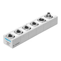
Festo CP-A04-M12-CL Manual (134 pages)
Compact performance
Brand:
Festo
| Category:
Control Unit
| Size: 1.82 MB
Table of Contents
Table of Contents
5
Intended Use
8
Selecting the Power Unit
9
Target Group
9
Service
9
Important User Instructions
10
Notes on the Use of this Manual
12
1 System Overview CPI/CP System
17
Setting up CPI Systems
19
Method of Operation of the CPI/CP System
21
Rules for Extending the CPI System
24
Use of the I/O Modules
27
Basic Rules for Addressing
29
2 Input Modules Types CP−E08−M
31
Input Modules Types Cp−E08−M −Cl and Cp−E16−Kl−Cl
32
Function of the Input Modules CP−E08−M
33
Display and Connecting Elements
34
Mounting
35
Mounting
36
Mounting
37
Installation
38
Connecting Sensors
39
Connect the Input Module to the CP String
42
Diagnosis
44
Diagnosis Via Leds
44
Diagnosis Via the Field Bus
47
Output Module Type CP−A04−M12−CL
49
Output Module Type Cp−A04−M12−Cl
50
Function of Output Module Type CP−A04−M12−CL
51
Display and Connecting Elements
52
Output Module Type CP−A04−M12
51
Mounting
53
Installation
54
Connecting the Actuators
55
Connect the Output Module to the CP String
56
Diagnostics
58
Diagnostics Via Leds
58
Diagnostics Via the Fieldbus
61
Input Modules Type CP−E16−M...−EL and CP−E32−M8−EL
63
Input Modules Type Cp−E16−M −El and Cp−E32−M8−El
64
Function of the Input Modules CP−E16−M
65
Display and Connecting Elements
66
Input Modules Type CP−E16−M
65
Mounting
69
Labelling of Inscription Label Holder
71
Installation
72
Connecting Sensors
73
Connect the Input Module to the CP String
76
Diagnostics
78
Diagnostics Via Leds
78
Diagnostics Using Fieldbus
82
Output Module Type Cp−A08−M12−El−Z
84
Function of the Output Module Type CP−A08−M12−EL−Z
85
Display and Connecting Elements
86
Output Module Type CP−A08−M12−EL−Z
85
Mounting
87
Labelling of Inscription Label Holder
89
Installation
90
Connect External Load Supply
91
Connecting the Actuators
92
Connect the Output Module to the CP String
93
Diagnostics
95
Diagnostics Via Leds
95
Diagnostics Using Fieldbus
98
A. Technical Appendix
100
A.1 Technical Specifications
101
A.1.2 Technical Specifications of the CL Input Modules
102
A.1.3 Technical Specifications of the CL Output Modules
104
A.1.4 Technical Specifications of the el Input Modules
105
A.1.5 Technical Specifications of the el Output Modules
107
A.2 Internal Structure of the Inputs
108
A.2.2 Internal Structure Type CP−E08−M12−CL and CP−E16−M12−EL
109
A.2.3 Internal Structure Type CP−E08−M8−CL and CP−E16−M8−EL
110
A.2.4 Internal Structure Type CP−E16−KL−CL
111
A.3 Internal Structure of the Outputs
112
A.4 Examples of Circuitry
113
A.4.2 Circuitry Examples for Outputs
118
A.5 General Information on Parameterisation
120
A.5.2 Signal Extension (Only with CP−EL Modules)
122
A.6 Accessories
125
A.6.3 Accessories for Modules with M8 Connection
126
A.6.4 Connector Sets for Input Module Type CP−E16−KL−CL
127
B. Index
130
Advertisement
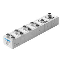
Festo CP-A04-M12-CL Manual (86 pages)
CP modules
Brand:
Festo
| Category:
I/O Systems
| Size: 2.98 MB
Table of Contents
Table of Contents
5
Designated Use
7
Service
8
Target Group
8
Important User Instructions
9
Notes on the Use of this Manual
11
1 System Summary CP System
15
Setting up CP Systems
17
Method of Operation of the CP System
19
Variants of the CP System
21
Use of the I/O Modules
25
Basic Rules for Addressing
27
Input Modules Type CP−E08−M...−CL and CP−E16−KL−CL
29
Input Modules Type Cp−E08−M −Cl and Cp−E16−Kl−Cl
30
2 Input Modules Type CP−E08−M
30
Function of the Input Modules CP−E08−M
31
Display and Connecting Elements
32
Input Modules Type CP−E08−M
32
Fitting
35
Installation
36
Connecting Sensors
37
Connect the Input Module to the CP String
40
Diagnosis
42
Diagnosis Via Leds
42
Diagnosis Via the Field Bus
45
2.1 Function of the Input Modules CP−E08−M
32
Output Modules Type Cp−A04−M12−Cl
48
Function of Output Module Type CP−A04−M12−CL
49
Display and Connecting Elements
50
Output Modules Type CP−A04−M12−CL
49
Fitting
51
Installation
52
3.3 Installation
53
Connecting the Actuators
53
Connect the Output Module to the CP String
54
3.2 Fitting
53
Diagnosis
56
Diagnosis Via Leds
56
Diagnosis Via the Field Bus
59
A. Technical Appendix
62
A.1 Technical Specifications
63
A.1.2 Technical Specifications of the Input Modules
64
A.1.3 Technical Specifications of the Output Modules
66
A.2 Internal Structure of the Inputs
67
A.2.2 Internal Structure Type CP−E08−M8−CL
68
A.2.3 Internal Structure Type CP−E16−KL−CL
69
A.3 Internal Structure of the Outputs
70
A.4 Examples of Circuitry
71
A.4.2 Circuitry Example for Outputs
75
A.5 Accessories
77
A.5.3 Accessories for Modules with M8 Connection
78
A.5.4 Connector Sets for Input Module Type CP−E16−KL−CL
79
B. Index
82
B.1 Index
83
Advertisement
Related Products
Festo CP-A08-M12-EL-Z
Festo CPA VI Series
Festo CPA10VI
Festo CPA14VI
Festo CPASC-DN
Festo CPA-SC Series
Festo CPA-SC-DP
Festo CPX-FB32
Festo CPE PRSG-3 Series
Festo CPV10-GE-DI02-8
Festo Categories
Industrial Equipment
Control Unit
Controller
Touch terminals
DC Drives
More Festo Manuals
Login
Sign In
OR
Sign in with Facebook
Sign in with Google
Upload manual
Upload from disk
Upload from URL