User Manuals: Daikin H-Series Heat Pump
Manuals and User Guides for Daikin H-Series Heat Pump. We have 11 Daikin H-Series Heat Pump manuals available for free PDF download: Service Manual, Engineeiring Data, Engineering Data, Technical Manual, Installation Instructions Manual
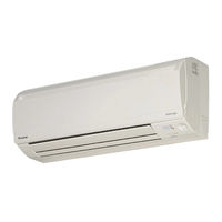
Daikin H-Series Service Manual (289 pages)
Inverter Multi for 2 Rooms
Brand: Daikin
|
Category: Air Conditioner
|
Size: 14 MB
Table of Contents
Advertisement
Daikin H-Series Engineeiring Data (124 pages)
H-Series Heat Pump SEER 13 Models Split-System Room Air Conditioners
Brand: Daikin
|
Category: Air Conditioner
|
Size: 12 MB
Table of Contents
Advertisement
Daikin H-Series Engineering Data (108 pages)
H-Series Cooling Only / Heat Pump Split-System Room Air Conditioners
Brand: Daikin
|
Category: Air Conditioner
|
Size: 15 MB
Table of Contents

Daikin H-Series Technical Manual (103 pages)
Split Systems Air Conditioner Ducted Blower
Brand: Daikin
|
Category: Air Conditioner
|
Size: 20 MB
Table of Contents

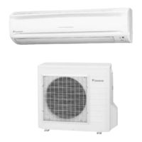
Daikin H-Series Service Manual (113 pages)
SPLIT Pair


Daikin H-Series Technical Manual (80 pages)
Split Systems Air Conditioner Ducted Blower
Brand: Daikin
|
Category: Air Conditioner
|
Size: 4 MB
Table of Contents

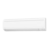
Daikin H-Series Service Manual (56 pages)
Non-Inverter Pair Wall Mounted Type
Brand: Daikin
|
Category: Air Conditioner
|
Size: 2 MB
Table of Contents

Daikin H-Series Installation Instructions Manual (28 pages)
13.4 SEER2 With R-410A Self-Contained Package Air Conditioners and Heat Pump Units
Brand: Daikin
|
Category: Air Conditioner
|
Size: 2 MB
Table of Contents
Daikin H-Series Installation Instructions Manual (20 pages)
15.2 SEER2 Self-contained Package Air Conditioners and Heat Pump Units With R 410A
Brand: Daikin
|
Category: Air Conditioner
|
Size: 1 MB
Table of Contents
Advertisement