Table of Contents
Advertisement
Quick Links
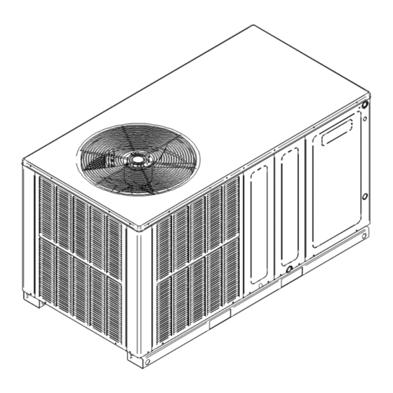
Installation Instructions for
DP5HH 15.2 SEER2 "H" Series Self-contained Package Air
Conditioners and Heat Pump Units With R-410A
ATTENTION INSTALLING PERSONNEL
Prior to installation, thoroughly familiarize yourself with this
Installation Manual. Observe all safety warnings. During
installation or repair, caution is to be observed.
It is your responsibility to install the product safely and to
educate the customer on its safe use.
RECOGNIZE THIS SYMBOL
AS A SAFETY PRECAUTION.
These installation instructions cover the outdoor installation
of self contained package air conditioner and heating units.
See the Specification Sheets applicable to your model for
information regarding accessories.
*NOTE: Please contact your distributor or our website for
the applicable Specifications Sheets referred to in this
manual.
Our continuing commitment to quality products may mean a change in specifications without notice.
© 2021
IOD-3023
12/2021
Only personnel that have been trained to install, adjust,
service or repair(hereinafter, "service") the equipment
specified in this manual should service the equipment. The
manufacturer will not be responsible for any injury or
property damage arising from improper service or service
procedures. If you service this unit, you assume responsi-
bility for any injury or property damage which may result.
In addition, in jurisdictions that require one or more
licenses to service the equipment specified in this manual,
only licensed personnel should service the equipment.
Improper installation, adjustment, servicing or repair of
the equipment specified in this manual, or attempting to
install, adjust, service or repair the equipment specified in
this manual without proper training may result in product
damage, property damage, personal injury or death.
Do not bypass safety devices.
TO THE INSTALLER .........................................................2
SHIPPING INSPECTION ...................................................2
Checking Product Received .......................................2
Message to the Homeowner .......................................2
REPLACEMENT PARTS ...................................................2
Ordering Parts .............................................................2
IMPORTANT SAFETY INSTRUCTIONS ...........................2
Recognize Safety Symbols, Words, and Labels ....2
CODES AND REGULATIONS .........................................3
General ..........................................................................3
EPA Regulations ...........................................................3
National Codes .............................................................3
MAJOR COMPONENTS ....................................................3
General ..........................................................................3
INSTALLATION ..................................................................4
Pre-Installation Checkpoints ....................................4
Clearance ......................................................................4
Location .........................................................................4
Outside Slab Installation .........................................4
Rooftop Installation ..................................................4
19001 Kermier Rd. Waller, Tx 77484
www.daikincomfort.com
INSTALLATION INSTRUCTIONS
WARNING
WARNING
Table of Contents
Advertisement
Table of Contents
Troubleshooting

Related Manuals for Daikin DP5HH2441 Series


Summary of Contents for Daikin DP5HH2441 Series
- Page 1 INSTALLATION INSTRUCTIONS Installation Instructions for DP5HH 15.2 SEER2 “H” Series Self-contained Package Air Conditioners and Heat Pump Units With R-410A WARNING Only personnel that have been trained to install, adjust, service or repair(hereinafter, “service”) the equipment specified in this manual should service the equipment. The manufacturer will not be responsible for any injury or property damage arising from improper service or service procedures.
-
Page 2: Table Of Contents
Undercharge ..............13 Poor “Terminating” Sensor Contact ....13 HOMEOWNER SUPPORT Malfunctioning Reversing Valve ......13 DAIKIN NORTH AMERICA LLC BLOWER PERFORMANCE DP5HH 15.2 SEER2 ..14 19001 KERMIER ROAD WALLER, TX 77484 TROUBLESHOOTING CHART ........15 855-770-5678 START-UP CHECKLIST ..........17... - Page 3 CODES AND REGULATIONS WARNING General To avoid property damage, personal injury or death, do not The DP*HH series heat pumps are designed for use this unit if any part has been under water. Immediately OUTDOOR USE ONLY. This series is available in cooling call a qualified service technician to inspect the furnace Capacities of 2, 2 ½, 3, 3 ½, 4 and 5 nominal tons of and to replace any part of the control system and any gas...
- Page 4 INSTALLATION Heat pumps require special location consideration in areas of heavy snow accumulation and/or areas with prolonged continuous subfreezing temperatures. Heat pump unit Pre-Installation Checkpoints bases have holes under the outdoor coil to permit drainage Before attempting any installation, the following points of defrost water accumulation.
-
Page 5: Ducting
32.5:” and 36” SQRPCH103 (See Specification Sheets for Dimension details). The SQRPCH101 has 14” duct collar 36" on supply and 16” duct collar (equivalent diameter, opening is oval) on the return. The SQRPCH102 and SQRPCH103 have 14” duct collar on supply and 18” duct collar (equivalent diameter, opening is oval) on the return. -
Page 6: Plenum Application
Plenum Application Install a branch circuit fused disconnect near the unit, in A suitable plenum or square duct must be constructed. The accordance with the N.E.C. or local codes. Wire sizes and duct cross-sectional area should be determined by industry overcurrent protection should be determined from the unit duct sizing manuals or air duct calculators. -
Page 7: High Voltage Wiring
1. For branch circuit wiring (main power supply to unit WARNING disconnect), the minimum wire size for the length of the run can be determined from Table 4 using the circuit ampacity found on the unit rating plate. From HIGH VOLTAGE! the unit disconnect to unit, the smallest wire size Disconnect all power before servicing or in- stalling this unit. -
Page 8: Heat Pump Start-Up Procedure
Heat Pump Start-Up Procedure If the out door ambient is low and the unit operates 9. Check the cooling mode for the heat pump in properly on the heating cycle, you may check the the same manner as above. The reversing valve pressure cutout operation by blocking off the indoor is energized when the thermostat is placed in return air until the unit trips. -
Page 9: Final System Checks
Final System Checks below to permit staging of indoor supplement heater 16. Check to see if all supply and return air grilles are operation. If the outdoor ambient temperature is adjusted and the air distribution system is balanced below 0°F (-18°C) with 50% or higher RH, an outdoor for the best compromise between heating and thermostat (OT) must be installed and set at (0°) on cooling. -
Page 10: Defrost Control
SUGGESTED FIELD TESTING/ Figure 7 shows a schematic of a heat pump on the cooling cycle and the heating cycle. In addition to a reversing TROUBLESHOOTING valve, a heat pump is equipped with an expansion device and check valve for the indoor coil, and similar equipment 1. -
Page 11: Adjusting Speed Tap For Indoor Blower Motor
In general 400 CFM per ton of cooling capacity is a rule SUPERHEAT CAN BE DETERMINED AS FOLLOWS: of thumb. Some applications depending on the sensible and latent capacity requirements may need only 350 1. Read suction pressure. Determine Saturated CFM or up to 425 CFM per ton. -
Page 12: Expansion Valve (Txv) System Single Speed Application (Dp5Hh24-36)
Expansion Valve (TXV) System a. If subcooling and superheat are low, adjust TXV superheat, then check subcooling. Single Speed Application (DP5HH24-36) Purge gauge lines. Connect service gauge manifold to NOTE: To adjust superheat, turn the valve stem access fittings. Run system at least 10 minutes to allow clockwise to increase and counter clockwise to pressure to stabilize. -
Page 13: Maintenance
Common Causes of Unsatisfactory Operation of Heat DP5HH (24-60) Models (0 - 0.5 E.S.P.) Pump on the Heating Cycle. Electric Heat KW Unit Model Number Inadequate Air Volume Through Indoor Coil DP5HH2441** When a heat pump is in the heating cycle, the indoor coil DP5HH3041** is functioning as a condenser. -
Page 14: Blower Performance Dp5Hh 15.2 Seer2
DP5HH(24 - 60)41 BLOWER PERFORMANCE DP5HH[24-60]41 BLOWER PERFORMANCE NEW E.S.P. (In. of H Model Speed Volts Watts 1138 1079 1030 T2 / T3 Watts 1231 1179 1127 1074 1022 T4 / T5 Watts 1005 Watts 1342 1288 1236 1185 1135 1082 1010 T2 / T3... -
Page 15: Troubleshooting Chart
TROUBLESHOOTING CHART HIGH VOLTAGE! WARNING ISCONNECT POWER BEFORE SERVICING OR INSTALLING THIS UNIT ULTIPLE POWER SOURCES MAY BE PRESENT AILURE TO DO SO MAY CAUSE PROPERTY DAMAGE PERSONAL INJURY OR DEATH POSSIBLE CAUSE REMEDY SYMPTOM High head - low suction a. - Page 16 PACKAGE UNITS - HEAT PUMP AND AC UNITS HOMEOWNER’S ROUTINE MAINTENANCE RECOMMENDATIONS We strongly recommend a bi-annual maintenance checkup be performed by a qualified service agency before the heating and cooling seasons begin. Replace or Clean Filter Aluminum Indoor Coil Cleaning (Qualified Servicer Only) WARNING This unit is equipped with an aluminum tube evaporator...
-
Page 17: Start-Up Checklist
START-UP CHECKLIST Residential Package - (Indoor Section) Model Number Serial Number ELECTRICAL Line Voltage (Measure L1 and L2 Voltage) L1 - L2 Secondary Voltage (Measure Transformer Output Voltage) R - C Blower Amps Heat Strip 1 - Amps Heat Strip 2 - Amps BLOWER EXTERNAL STATIC PRESSURE Return Air Static Pressure IN. - Page 18 THIS PAGE LEFT INTENTIONALLY BLANK.
- Page 19 THIS PAGE LEFT INTENTIONALLY BLANK.
- Page 20 CUSTOMER FEEDBACK Daikin is very interested in all product comments. Please fill out the feedback form on the following link: https://daikincomfort.com/contact-us You can also scan the QR code on the right to be directed to the feedback page. PRODUCT REGISTRATION Thank you for your recent purchase.
Need help?
Do you have a question about the DP5HH2441 Series and is the answer not in the manual?
Questions and answers